

Page 1

MK V and MK VII
Enhanced Ground Proximity Warning System Pilot's Guide
060-4241-000 • Rev. D - March 2000
MK V & MK VII EGPWS Pilot Guide
1
Page 2

This document is an unpublished work
Copyright 2001
Honeywell International Inc.
All rights reserved
This document and all information and expression
contained herein are the property of Honeywell International Inc., and is provided to the recipient in
confidence on a “need to know” basis. Your use of
this document is strictly limited to a legitimate business purpose requiring the information contained
therein. Your use of this document constitutes acceptance of these terms.
2 MK V & MK VII EGPWS Pilot Guide
060-4241-000 • Rev. D - March 2000
Page 3

TABLE OF CONTENTS
SECTION 1 Introduction ...................................................................... 4
SECTION 2 System Description ............................................................7
SECTION 3 Operational Procedures ...................................................46
SECTION 4 Definitions .......................................................................57
Request for Information ......................................................................59
060-4241-000 • Rev. D - March 2000
MK V & MK VII EGPWS Pilot Guide
3
Page 4

S
ECTION
1
Introduction
What is the
EGPWS?
This Pilot Guide describes the functions and operation of the
MKV and MKVII Enhanced Ground Proximity Warning System
(EGPWS).
The document is divided into four sections. Section 1 is this
introduction and the following brief description of the EGPWS
and its features. Section 2 provides a functional description of
the EGPWS. This includes descriptions of the various system
modes, Built-In Test (BIT) and monitoring functions, and
system features. Section 3 provides general operating
procedures to follow when the system gives a caution or
warning alert. Section 4 provides definitions of terms used in
this manual.
This guide does not supercede FAA approved data, Flight
Manuals, individual Operations Manuals, requirements, or
procedures. Pilots should be thoroughly familiar with their
own company policies, system configuration, requirements,
and procedures with respect to the operation of aircraft with
the EGPWS.
The information in this document is intended as a general
explanation of the Honeywell EGPWS. It contains a general
description of system performance assuming identified options
are active, and highlights deviations in system performance
resulting when a feature is disabled.
The EGPWS is a Terrain Awareness and Alerting system
providing terrain alerting and display functions with additional
features.
The EGPWS uses aircraft inputs including geographic position,
attitude, altitude, airspeed, and glideslope deviation. These are
used with internal terrain, obstacles, and airport databases to
predict a potential conflict between the aircraft flight path and
terrain or an obstacle. A terrain or obstacle conflict results in
the EGPWS providing a visual and audio caution or warning alert.
Additionally, the EGPWS provides alerts for excessive glideslope
deviation, too low with flaps or gear not in landing configuration, and optionally provides bank angle and altitude callouts
based on system program pin selection. Detection of severe
windshear conditions is also provided for selected
aircraft types when enabled.
4 MK V & MK VII EGPWS Pilot Guide
060-4241-000 • Rev. D - March 2000
Page 5

What is the
EGPWS?
continued
The EGPWS incorporates several “enhanced” features:
• Terrain Alerting and Display (TAD) provides a graphic dis-
play of the surrounding terrain on the Weather Radar
Indicator, EFIS, or a dedicated display. Based on the
aircraft’s position and the internal database, the terrain
topography (within the display range selected) that is above
or within 2000 feet below the aircraft altitude is presented on
the system display. This feature is an option, enabled by
program pins during installation.
• “Peaks” is a TAD supplemental feature providing additional
terrain display features for enhanced situational awareness,
independent of the aircraft’s altitude. This includes digital
elevations for the highest and lowest displayed terrain,
additional elevation (color) bands, and a unique representation of 0 MSL elevation (sea level and its corresponding
shoreline). This feature is an option, enabled by program
pins during installation.
• “Obstacles” is a feature utilizing an obstacle database for
obstacle conflict alerting and display. EGPWS caution and
warning visual and audio alerts are provided when a conflict
is detected. Additionally, when TAD is enabled, Obstacles are
graphically displayed similar to terrain. This feature is an
option, enabled by program pins during installation.
•A process feature called Envelope Modulation utilizes the
internal database to tailor EGPWS alerts at certain geographic
locations to reduce nuisance alerts and provide added
protection.
•A Terrain Clearance Floor feature adds an additional
element of protection by alerting the pilot of possible
premature descent. This is intended for non-precision
approaches and is based on the current aircraft position
relative to the nearest runway. This feature is enabled with
the TAD feature.
• In -210-210 and later versions, a Runway Field Clear-
ance Floor (RFCF) feature is included. This is similar to
the TCF feature except that RFCF is based on the current aircraft position and height above the destination runway
based on Geometric Altitude (see below). This provides improved protection at locations where the destination runway
is significantly higher than the surrounding terrain.
060-4241-000 • Rev. D - March 2000
MK V & MK VII EGPWS Pilot Guide
5
Page 6

What is the
EGPWS?
continued
Physical
Description
• An Aural Declutter feature reduces the repetition of warning messages. This feature is optional, and may be disabled
by system program pins during installation.
• Geometric Altitude, based on GPS altitude, is a computed
pseudo-barometric altitude designed to reduce or eliminate
altitude errors resulting from temperature extremes, nonstandard pressure altitude conditions, and altimeter
miss-sets. This ensures an optimal EGPWS alerting and display capability.
Some of these features have been added to the EGPWS as the
system evolved and are not present in all Enhanced Ground
Proximity Warning Computer (EGPWC) part numbers. For specific effectivity, refer to an applicable Airplane Flight Manual
(AFM) or EGPWS Airplane Flight Manual Supplement (AFMS) or
contact Honeywell for assistance.
The EGPWC is packaged in a 2 MCU ARINC 600-6 rack mounted
enclosure weighing less than 8 lbs. No special vibration isolation
mounting or forced air-cooling is required.
115 VAC (400 Hz.) or 28 VDC versions of the EGPWC are available. Units are also available with an internal GPS receiver for
required GPS data when another GPS source is not available.
For more detailed descriptions and information, contact
Honeywell.
6 MK V & MK VII EGPWS Pilot Guide
060-4241-000 • Rev. D - March 2000
Page 7

S
ECTION
2
System Description
Enhanced Ground Proximity Warning System ...............................6
EGPWS Database ................................................................................... 6
Basic Functions:
Mode 1 - Excessive Descent Rate .......................................................... 8
Mode 2 - Excessive Closure to Terrain .................................................. 9
Mode 3 - Altitude Loss After Takeoff.....................................................12
Mode 4 - Unsafe Terrain Clearance ..................................................... 13
Mode 5 - Excessive Deviation Below Glideslope .................................. 17
Mode 6 - Advisory Callouts ................................................................. 19
Mode 7 - Windshear Alerting .............................................................. 23
Enhanced Functions:
Envelope Modulation.......................................................................... 25
Ter rain Clearance Floor...................................................................... 25
Runway Field Clearance Floor ............................................................. 27
Ter rain Look Ahead Alerting ................................................................ 27
Ter rain Alerting and Display ................................................................29
Non-Peaks Display ............................................................................... 30
Pop-Up and Auto-Range ...................................................................... 32
Peaks Display ...................................................................................... 32
Geometric Altitude............................................................................... 36
Weather Radar Auto-Tilt .......................................................................37
Aural Message Priority ........................................................................ 37
System Inputs .................................................................................. 39
System Outputs .................................................................................41
Options............................................................................................... 41
060-4241-000 • Rev. D - March 2000
MK V & MK VII EGPWS Pilot Guide
7
Page 8
Enhanced
Ground
Proximity
Warning
System
EGPWS
Database
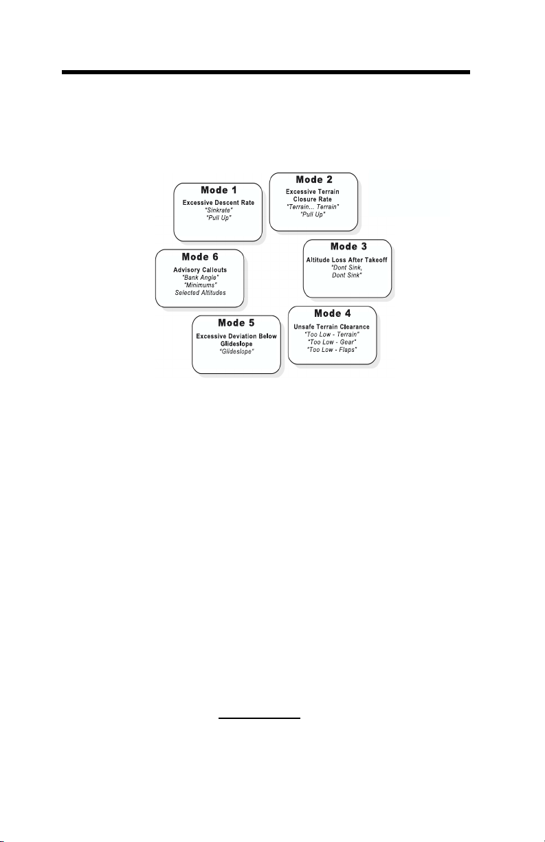
The EGPWS incorporates the functions of the basic Ground
Proximity Warning System (GPWS). This includes the following
alerting modes:
Additionally, Windshear alerting (Mode 7) is provided for specific aircraft types. Mode 7 provides windshear caution and/or
warning alerts when an EGPWS windshear threshold is exceeded.
The EGPWS adds to these 7 basic functions the ability to compare the aircraft position to an internal database and provide
additional alerting and display capabilities for enhanced situational awareness and safety (hence the term “Enhanced”
GPWS).
The EGPWS internal database consists of four sub-sets:
1. A worldwide terrain database of varying degrees of resolution.
2. An obstacles database containing cataloged obstacles 100
feet or greater in height located within North America and
portions of the Caribbean (expanding as data is obtained).
3. A worldwide airport database containing information on
hard-surface runways 3500 feet or longer in length. For a
specific list of the airports included, refer to Honeywell
document 060-4267-000 or access on the Internet at
website www.egpws.com.
4. An Envelope Modulation database to support the Envelope
Modulation feature discussed later.
8 MK V & MK VII EGPWS Pilot Guide
060-4241-000 • Rev. D - March 2000
Page 9

EGPWS
Database
continued
Honeywell is constantly striving to improve the EGPWS database in content, resolution, and accuracy. Notification of a
Database update is accomplished by Service Bulletin. Database updates are distributed on PCMCIA data cards and
downloaded via a card slot in the front panel of each EGPWC.
Contact Honeywell for additional information.
Because the overwhelming majority of “Controlled Flight Into
Te rrain” (CFIT) accidents occur near an airport, and the fact
that aircraft operate in close proximity to terrain near an airport, the terrain database contains higher resolution grids for
airport areas. Lower resolution grids are used outside airport
areas where aircraft enroute altitude make CFIT accidents less
likely and terrain feature detail is less important to the flight
crew.
With the use of accurate GPS or FMS information, the EGPWS
is provided present position, track, and ground speed. With
this information the EGPWS is able to present a graphical plan
view of the aircraft relative to the terrain and advise the flight
crew of a potential conflict with the terrain or obstacle. Conflicts are recognized and alerts provided when terrain violates
specific computed envelope boundaries on the projected flight
path of the aircraft. Alerts are provided in the form of visual
light annunciation of a caution or warning, audio enunciation
based on the type of conflict, and color enhanced visual display
of the terrain or obstacle relative to the forward look of the aircraft. The terrain display is provided on the Weather Radar
Indicator, EFIS display, or a dedicated EGPWS display and may
or may not be displayed automatically.
The following sections provide functional descriptions of the
EGPWS basic and enhanced functions and features, and system input and output requirements.
060-4241-000 • Rev. D - March 2000
MK V & MK VII EGPWS Pilot Guide
9
Page 10
BASIC FUNCTIONS:
MODE 1
Excessive
Descent
Rate
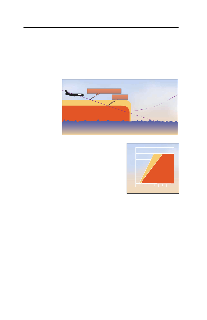
Mode 1 provides alerts for excessive descent rates with respect
to altitude AGL and is active for all phases of flight. This mode
has inner and outer alert boundaries as illustrated in the
diagram and graph below.
Penetration of the outer boundary activates the EGPWS caution
"SINKRATE"
"SINKRATE SINKRATE"
"PULL UP"
"PULLUP"
3000
2500
2000
"SINKRATE"
1500
1000
Radio Altitude (FEET)
500
0
2000 4000 6000 8000 1000
Descent Rate (FEET/MINUTE)
0
"PULL UP!"
lights and “SINKRATE, SINKRATE” alert enunciation.
Additional “SINKRATE, SINKRATE ” messages will occur for
each 20% degradation.
Penetration of the inner boundary activates the EGPWS
warning lights and changes the audio message to “PULL UP”
which repeats continuously until the inner warning boundary
is exited.
Note: “Pull Up” may be preceded by “Whoop, Whoop” in
some configurations based on the audio menu option selected.
Glideslope
Deviation
Bias
If a valid ILS Glideslope front course is received and the aircraft
is above the glideslope centerline, the outer (sinkrate)
boundary is adjusted to desensitize the sinkrate alerting. This
is to prevent unwanted alerts when the aircraft is safely
capturing the glideslope (or repositioning to the centerline)
from above the beam.
10 MK V & MK VII EGPWS Pilot Guide
060-4241-000 • Rev. D - March 2000
Page 11

M
ODE
1
Continued
Steep
Approach
Bias
MODE 2
Excessive
Closure to
Terrain
MODE 2A
If the Aural Declutter feature is disabled, the sinkrate alert
boundary remains fixed and the aural message “SINKRATE”
repeats continuously until the outer boundary is exited.
The EGPWS offers a Steep Approach option for given aircraft
types that desensitizes the alert boundaries to permit steeper
than normal approaches without unwanted alerts.
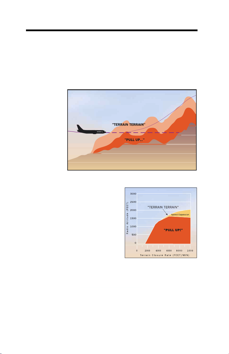
Mode 2 provides alerts to help protect the aircraft from
impacting the ground when rapidly rising terrain with respect
to the aircraft is detected. Mode 2 is based on Radio Altitude
and on how rapidly Radio Altitude is decreasing (closure rate).
Mode 2 exists in two forms, 2A and 2B.
Mode 2A is active during climbout, cruise, and initial approach
(flaps not in the landing configuration and the aircraft not on
glideslope centerline). If the aircraft penetrates the Mode 2A
caution envelope, the aural message “TERRAIN, TERRAIN” is
generated and cockpit EGPWS caution lights will illuminate. If
the aircraft continues to penetrate the envelope, the EGPWS
warning lights will illuminate and the aural warning message
“PULL UP” is repeated continuously until the warning
envelope is exited.
Note: “Pull Up” may be preceded by “Whoop, Whoop” in some
configurations based on the audio menu option selected.
Upon exiting the warning envelope, if terrain clearance
continues to decrease, the aural message “TERRAIN” will be
given until the terrain clearance stops decreasing. In addition,
the visual alert will remain on until the aircraft has gained 300
feet of barometric altitude, 45 seconds has elapsed, or landing
flaps or the flap over-ride switch is activated.
060-4241-000 • Rev. D - March 2000
MK V & MK VII EGPWS Pilot Guide
11
Page 12
M
ODE 2A
Continued
The graph below shows how the upper boundary of the Mode 2
alert envelope varies as a function of the aircraft speed. As
airspeed increases from 220 knots to 310 knots, the boundary
expands to provide increased alert times at higher airspeeds.
With version -210-210 and later models, the Mode 2A upper
limit is reduced to 1250 feet for all airspeeds when the Terrain
Alerting and Display (TAD) function is enabled and available.
This is due to the enhanced alerting capability provided with
TAD, resulting from high integrity GPS Altitude and Geometric
Altitude data. The Mode 2A envelope is lowered in order to
reduce the potential for nuisance alerts during an approach.
12 MK V & MK VII EGPWS Pilot Guide
060-4241-000 • Rev. D - March 2000
Page 13
M
ODE
2B
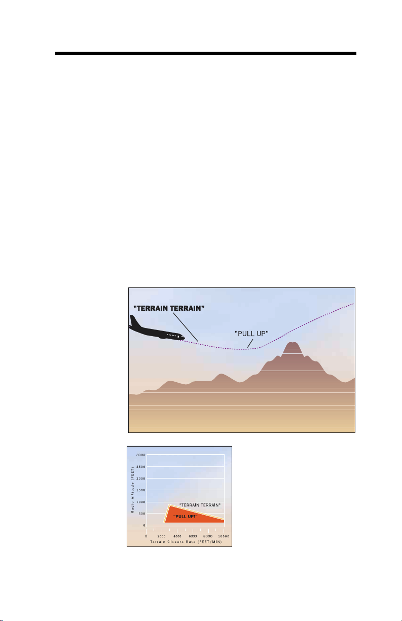
Mode 2B provides a desensitized alerting envelope to permit
normal landing approach maneuvers close to terrain without
unwanted alerts. Mode 2B is automatically selected with flaps
in the landing configuration (landing flaps or flap over-ride
selected) or when making an ILS approach with Glideslope
and Localizer deviation less than 2 dots. It is also active during
the first 60 seconds after takeoff.
With version -210-210 and later models, Mode 2B is selected
when the aircraft is within 5nm and 3500 feet of the
destination airport (independent of configuration) and the
Te rrain Alerting and Display (TAD) function is enabled and
available. This is due to the enhanced alerting capability
provided with TAD, resulting from high integrity GPS Altitude
and Geometric Altitude data. The Mode 2B envelope is
selected in order to reduce the potential for nuisance alerts
during an approach.
The graph above shows the Mode 2B envelope.
060-4241-000 • Rev. D - March 2000
MK V & MK VII EGPWS Pilot Guide
13
Page 14
M
ODE
2B
Continued
M
ODE
3
Altitude
Loss After
TakeOff
During an approach, if the aircraft penetrates the Mode 2B
envelope with either the gear or flaps not in the landing
configuration, the aural message “TERRAIN, TERRAIN” is generated and the EGPWS caution lights illuminate. If the
aircraft continues to penetrate the envelope, the EGPWS
warning lights illuminate and the aural message “PULL UP” is
repeated continuously until the warning envelope is exited. If
the aircraft penetrates the Mode 2B envelope with both gear
and flaps in the landing configuration, the aural “PULL UP”
messages are suppressed and the aural message “TERRAIN” is
repeated until the envelope is exited.
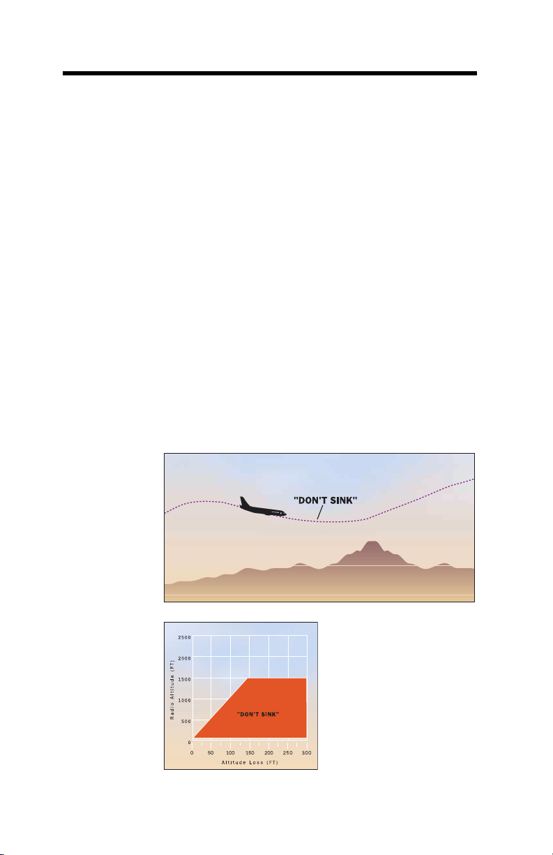
Mode 3 provides alerts for significant altitude loss after takeoff
or low altitude go-around (less than 245 feet AGL) with gear or
flaps not in the landing configuration. The amount of altitude
loss that is permitted before an alert is given is a function of the
height of the aircraft above the terrain as shown below. This
protection is available until the EGPWS determines that the
aircraft has gained sufficient altitude that it is no longer in the
takeoff phase of flight. Significant altitude loss after takeoff or
during a low altitude go-around activates the EGPWS caution
14 MK V & MK VII EGPWS Pilot Guide
060-4241-000 • Rev. D - March 2000
Page 15

M
ODE
3
Continued
M
ODE
4
Unsafe
Terrain
Clearance
lights and the aural message “DON’T SINK, DON’T SINK”. The
aural message is only enunciated twice unless altitude loss
continues. Upon establishing a positive rate of climb, the
EGPWS caution lights extinguish and the aural alert will cease.
If the Aural Declutter feature is disabled, the warning is
enunciated continuously until positive climb is established.
Mode 4 provides alerts for insufficient terrain clearance with
respect to phase of flight, configuration, and speed. Mode 4
exists in three forms, 4A, 4B, and 4C.
•Mode 4A is active during cruise and approach with the gear
and flaps not in the landing configuration.
•Mode 4B is active during cruise and approach with the gear
in the landing configuration and flaps not in the landing
configuration.
•Mode 4C is active during the takeoff phase of flight with
either the gear or flaps not in the landing configuration.
Mode 4 alerts activate the EGPWS caution lights and aural
messages.
To reduce nuisance alerts caused by over-flying another
aircraft, the upper limit of the Mode 4A/B alerting curve can be
reduced (from 1000) to 800 feet. This occurs if the airplane is
above 250 knots with gear and flaps not in landing
configuration and a sudden change in Radio Altitude is
detected. This is intended to eliminate nuisance alerts while
flying a holding pattern and an aircraft over-flight occurs (with
1000 foot separation).
With version -210-210 and later models, Mode 4 airspeed
expansion is disabled (upper limit held at lowest airspeed
limit) when the Terrain Alerting and Display (TAD) function is
enabled and available. This is due to the enhanced alerting
capability provided with TAD, resulting from high integrity GPS
Altitude and Geometric Altitude data. This change to the Mode
4 envelopes reduces the potential for nuisance alerts when the
aircraft is not in the landing configuration.
M
ODE 4A
060-4241-000 • Rev. D - March 2000
MK V & MK VII EGPWS Pilot Guide
Mode 4A is active during cruise and approach with gear and
flaps up. This provides alerting during cruise for inadvertent
flight into terrain where terrain is not rising significantly, or the
15
Page 16
M
ODE 4A
Continued
aircraft is not descending excessively. It also provides alerting
for protection against an unintentional gear-up landing.
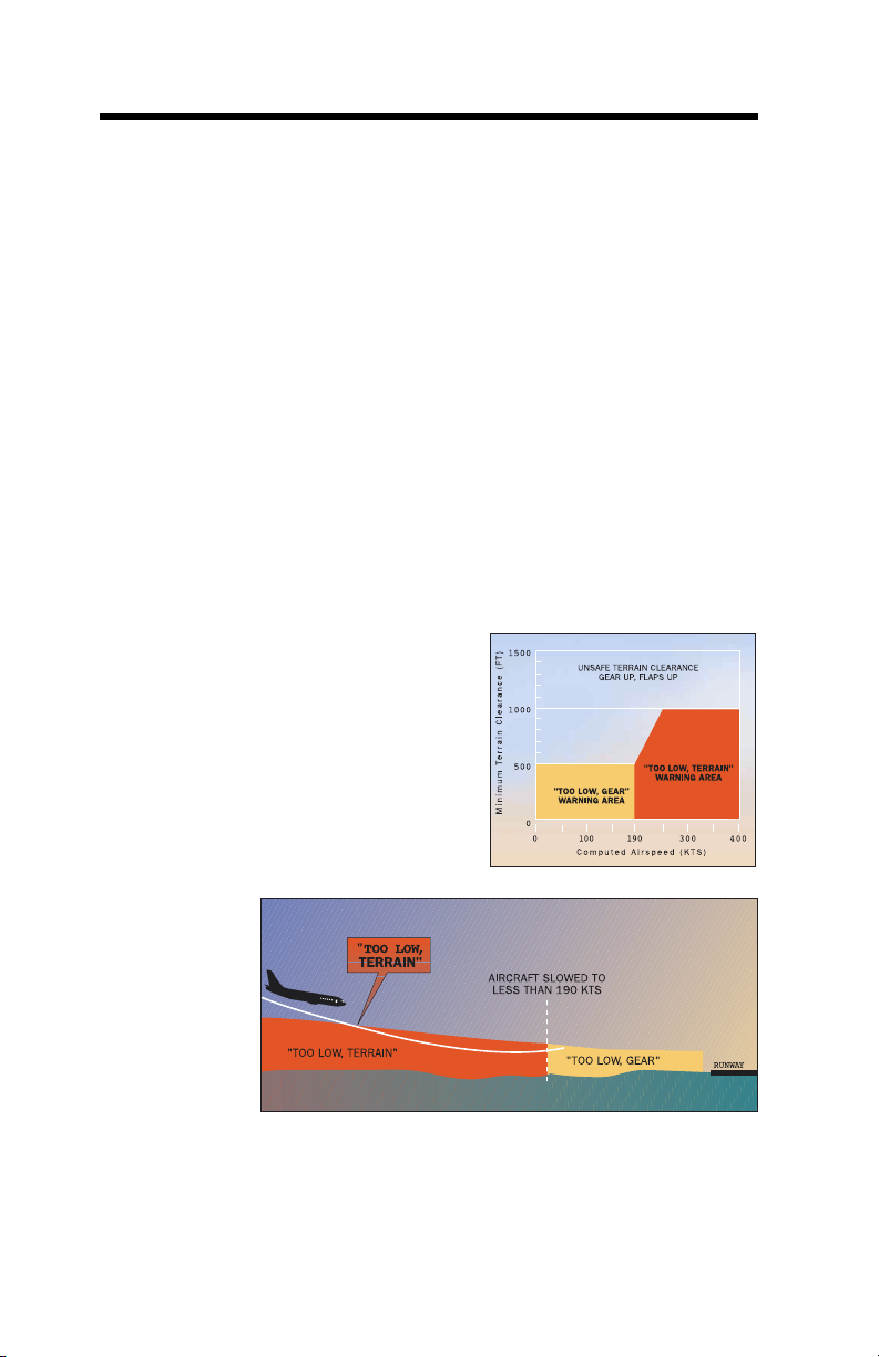
Below 1000 feet AGL and above 190 knots airspeed, the Mode
4A aural alert is “TOO LOW TERRAIN”. This alert is
dependent on aircraft speed such that the alert threshold is
ramped between 500 feet at 190 knots to 1000 feet at 250
knots.
Below 500 feet AGL and less than 190 knots airspeed, the
Mode 4A aural alert is “TOO LOW GEAR”.
For either Mode 4A alert, subsequent alert messages occur only
if penetration of the envelope increases by 20%. EGPWS
caution lights extinguish and aural messages cease when the
Mode 4A alert envelope is exited.
If the Aural Declutter feature is disabled, mode 4A alert
messages are repeated continuously until the Mode 4A
envelope is exited.
M
ODE 4B
Mode 4B is active during cruise and approach, with gear down
and flaps not in the landing configuration.
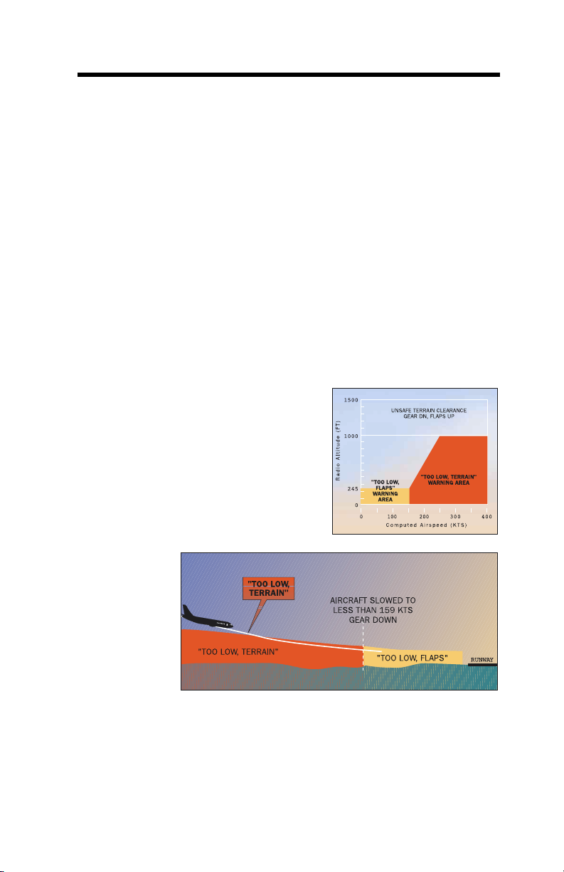
Below 1000 feet AGL and above 159 knots airspeed, the Mode
4B aural alert is “TOO LOW TERRAIN”. This alert is dependent
on aircraft speed such that the alert threshold is ramped be-
16 MK V & MK VII EGPWS Pilot Guide
060-4241-000 • Rev. D - March 2000
Page 17
M
ODE
4B
Continued
tween 245 feet at 159 knots to 1000 feet at 250 knots.
Below 245 feet AGL and less than 159 knots airspeed, the Mode
4B aural alert is “TOO LOW FLAPS”. For turboprop and select
turbofan aircraft, the “TOO LOW FLAPS” warning curve is
lowered to 150 feet AGL and less than 148 knots.
If desired, the pilot may disable the “TOO LOW FLAPS” alert by
engaging the Flap Override switch (if installed). This precludes
or silences the Mode 4B flap alert until reset by the pilot.
If the aircraft’s Radio Altitude decreases to the value of the MTC,
the EGPWS caution illuminates and the aural message “TOO
LOW TERRAIN” is enunciated.
For either Mode 4B alert, subsequent alert messages occur only
if penetration of the envelope increases by 20%. EGPWS caution
lights extinguish and aural messages cease when the Mode 4B
alert envelope is exited.
If the Aural Declutter feature is disabled, mode 4B alert
messages are repeated continuously until the Mode 4B
envelope is exited.
M
ODE
4C
The Mode 4C alert is intended to prevent inadvertent controlled
flight into the ground during takeoff climb into terrain that
produces insufficient closure rate for a Mode 2 alert. After
takeoff, Mode 4A and 4B provide this protection.
060-4241-000 • Rev. D - March 2000
MK V & MK VII EGPWS Pilot Guide
17
Page 18
M
ODE
4C
Continued
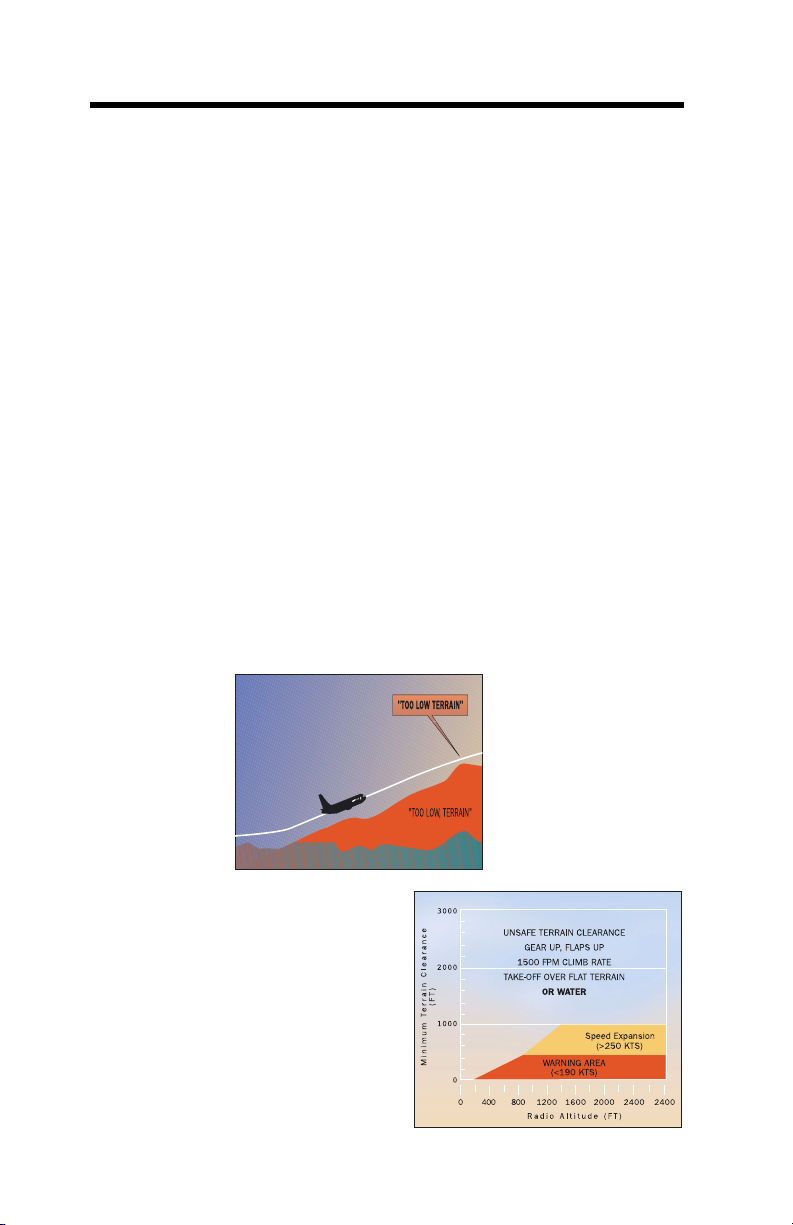
Mode 4C is based on an EGPWS computed Minimum Terrain
Clearance (MTC) floor, that increases with Radio Altitude. It is
active after takeoff when the gear or flaps are not in the landing
configuration. It is also active during a low altitude go-around
if the aircraft has descended below 245 feet AGL.
At takeoff the Minimum Terrain Clearance (MTC) is zero feet.
As the aircraft ascends the MTC is increased to 75% of the
aircraft’s Radio Altitude (averaged over the previous 15
seconds). This value is not allowed to decrease and is limited
to 500 feet AGL for airspeed less than 190 knots. Beginning at
190 knots, the MTC increases linearly to the limit of 1000 feet
at 250 knots.
If the aircraft’s Radio Altitude decreases to the value of the
MTC, the EGPWS caution illuminates and the aural message
“TOO LOW TERRAIN” is enunciated.
EGPWS caution lights extinguish and aural messages cease
when the Mode 4C alert envelope is exited.
If the Aural Declutter feature is disabled, mode 4C alert
messages are repeated continuously until the Mode 4C
envelope is exited.
18 MK V & MK VII EGPWS Pilot Guide
060-4241-000 • Rev. D - March 2000
Page 19
M
ODE
5
Excessive
Deviation
Below
Glideslope
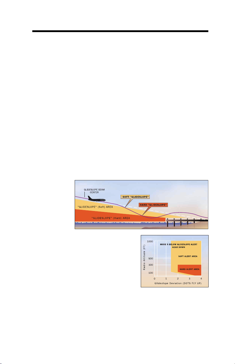
Mode 5 provides two levels of alerting for when the
aircraft descends below glideslope, resulting in
activation of EGPWS caution lights and aural messages.
The first level alert occurs when below 1000 feet Radio
Altitude and the aircraft is 1.3 dots or greater below the
beam. This turns on the caution lights and is called a
“soft” alert because the audio message “GLIDESLOPE”
is enunciated at half volume. 20% increases in the
glideslope deviation cause additional “GLIDESLOPE”
messages enunciated at a progressively faster rate.
The second level alert occurs when below 300 feet Radio
Altitude with 2 dots or greater glideslope deviation. This
is called a “hard” alert because a louder
“GLIDESLOPE, GLIDESLOPE” message is enunciated
every 3 seconds continuing until the “hard” envelope is
exited. The caution lights remain on until a glideslope
deviation less than 1.3 dots is achieved.
To avoid unwanted Below Glideslope alerts when
capturing the localizer between 500 and 1000 feet AGL,
alerting is varied in the following ways:
• Below Glideslope alerts are enabled only if the
060-4241-000 • Rev. D - March 2000
MK V & MK VII EGPWS Pilot Guide
localizer is within 2 dots, landing gear and flaps
are selected, Glideslope Cancel is not active, and
a front course approach is determined.
19
Page 20

M
ODE
5
Continued
• The upper altitude limit for the alert is modulated with
vertical speed. For descent rates above 500 FPM, the upper
limit is set to the normal 1000 feet AGL. For descent rates
lower than 500 FPM, the upper limit is desensitized
(reduced) to a minimum of 500 feet AGL.
Additionally, both alert levels are desensitized below 150 feet
AGL, to allow for normal beam variations nearer the ground,
and reduce the possibility of nuisance alerts.
If the Aural Declutter feature is disabled, messages are repeated
continuously until the Mode 5 envelope is exited.
Mode 5 alerts can be canceled by pressing the Glideslope
Cancel switch (if installed). The EGPWS will interpret this
switch one of two ways depending on the installation
configuration.
•A standard glideslope cancel switch allows for manually
canceling Mode 5 alerting any time below 2000 feet AGL.
This is automatically reset when the aircraft descends below
30 feet or climbs above 2000 feet AGL.
• An alternate glideslope cancel switch allows for manually
canceling Mode 5 alerting at any time and any altitude. The
cancel is reset by again pressing the cancel switch, or
automatically if gear or flaps are raised, or the aircraft is on
the ground. Due to the nature of the alternate cancel
switch, this method requires that there be a cockpit
annunciation that glideslope cancel is in effect.
EGPWS Mode 5 alerts are inhibited during backcourse
approaches to prevent nuisance alerts due to false fly up lobes
from the Glideslope. The EGPWC determines a backcourse
approach if either: 1) the aircraft’s magnetic track is greater
than 90 degrees from the runways approach course, or 2) a
glideslope inhibit discrete is set.
20 MK V & MK VII EGPWS Pilot Guide
060-4241-000 • Rev. D - March 2000
Page 21

M
ODE
6
Advisory
Callouts
Altitude
Callouts
Mode 6 provides EGPWS advisory callouts based on the
menu-selected option established at installation (set by
program pin configuration). These callouts consist of
predefined Radio Altitude based voice callouts or tones and an
excessive bank angle warning. There is no visual alerting
provided with these callouts.
The following is a list of each of the possible altitude callouts or
tones:
CALLOUT Occurs at (feet AGL)
“RADIO ALTIMETER” .......................................................... 2500
“TWENTY FIVE HUNDRED” ................................................ 2500
“ONE THOUSAND” ........................................................... 1000
“FIVE HUNDRED” ..............................................................500
Five Hundred Tone (2 second 960 Hz) ..................................500
“FOUR HUNDRED” .............................................................. 400
“THREE HUNDRED” ............................................................300
“TWO HUNDRED” ............................................................... 200
“APPROACHING MINIMUMS”......................................... DH+80
“APPROACHING DECISION HEIGHT” ........................... DH+100
“PLUS HUNDRED”...................................................... DH+100
“FIFTY ABOVE” ............................................................ DH+50
“MINIMUM” ......................................................................... DH
“MINIMUMS - MINIMUMS” ...................................................DH
“DECISION HEIGHT” ...........................................................DH
“DECIDE”............................................................................ DH
“ONE HUNDRED” ................................................................ 100
One Hundred Tone (2 second 700 Hz) ..................................100
“EIGHTY” .............................................................................. 80
“SIXTY” ................................................................................. 60
“FIFTY” ................................................................................. 50
“FORTY” ............................................................................... 40
“THIRTY FIVE” ...................................................................... 35
Thirty Five Tone (1 second 1400 Hz) ....................................... 35
“THIRTY” .............................................................................. 30
“TWENTY” ............................................................................. 20
Twenty Tone (1/2 second 2800 Hz) .........................................20
“TEN” ................................................................................... 10
“FIVE” .....................................................................................5
a. May be Barometric Altitude above the field elevation for some aircraft types.
a
a
060-4241-000 • Rev. D - March 2000
MK V & MK VII EGPWS Pilot Guide
21
Page 22

M
ODE
6
Continued
Smart
500 Foot
Callout
In some cases a callout is stated twice (e.g., “MINIMUMS,
MINIMUMS”) but in all cases a given callout is only enunciated
once per approach.
Decision Height (DH) based callouts (Approaching Minimums,
Minimums, etc.) require the landing gear to be down and
occur when descending through the Radio Altitude
corresponding to the selected DH. These also have priority over
other altitude callouts when overlapping. For example, if DH is
set to 200 and both “TWO HUNDRED” and “MINIMUMS” are
valid callouts, then only “MINIMUMS” will be called out at 200
feet AGL.
DH plus based callouts (e.g., Approaching Minimums) are only
applicable for aircraft providing a Decision Height altitude to the
EGPWS. Consequently, not all EGPWS installations can utilize
these callout options.
Due to the variety of altitude callout choices available, it is not
possible to identify every combination in this guide. Refer to an
appropriate Airplane Flight Manual or EGPWS Airplane Flight
Manual Supplement for callout identification in a specific
application or contact Honeywell.
Another feature available in the Altitude Callouts (options) is a
“Smart 500” foot callout. When selected, this callout assists
pilots during a non-precision approach by enunciating “FIVE
HUNDRED” feet in addition to any other altitude callout
discussed above. The EGPWS determines a non-precision
approach when Glideslope is greater than 2 dots deviation
(valid or not) or a back-course approach is detected.
This feature has the distinction of adding the 500-foot callout
during non-precision approaches and removing the 500-foot
callout on precision approaches when part of the callout option.
22 MK V & MK VII EGPWS Pilot Guide
060-4241-000 • Rev. D - March 2000
Page 23
M
ODE
6
Continued
Bank Angle
Callout
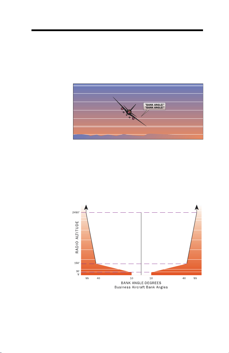
The callout “BANK ANGLE, BANK ANGLE” advises of an
excessive roll angle. The EGPWS provides several excessive
bank angle envelopes supporting Air Transport, Business, or
Military aircraft types (only Air Transport and Business are addressed below).
Business
Bank Angle
Air
Transport
Bank Angle
One envelope is defined for turbo-prop and jet business aircraft
(see graph below). Bank angles in excess of:
• ± 10° between 5 and 30 feet,
• ± 10 to 40° between 30 and 150 feet,
• ± 40 to 55° between 150 and 2450 feet,
produce the bank angle advisory (shaded area). Bank angle
advisories are inhibited below 5 feet.
Three envelopes are defined for Air Transport aircraft. These
are identified as Basic Bank Angle, Bank Angle Option 1, and
Bank Angle Option 2 advisories.
060-4241-000 • Rev. D - March 2000
MK V & MK VII EGPWS Pilot Guide
23
Page 24
M
ODE
6
Air Transport Bank
Angle
Continued
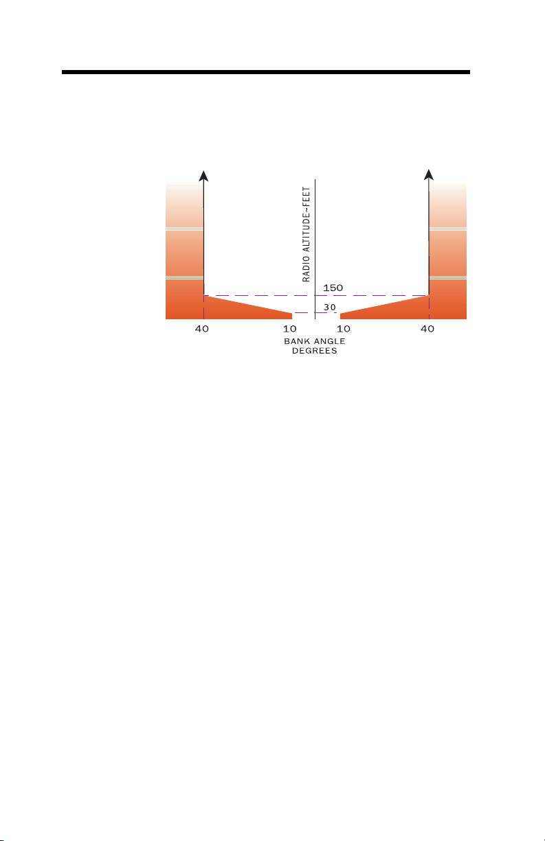
The Air Transport Basic Bank Angle limits are similar to the
Business Aircraft Bank Angle limits except above 150 feet the
bank limit remains at 40 as shown below.
Bank Angle Option 1 provides bank angle advisory thresholds at
35, 40, and 45 independent of altitude. In this case, an advisory
at 35 is provided and another is not given unless 40 is exceeded
and then again only if 45 is exceeded. If the roll rate exceeds the
audio callout time, then the bypassed limit is not indicated.
Also, when any one of the thresholds is exceeded, the bank
angle must reduce below 30 for the process to reset before
additional Bank Angle Advisories can be provided.
For example, if greater than 40 is obtained before the 35 callout
is complete, another callout is provided only if 45 is obtained or
the bank angle is reduced to less than 30 and then again
increases to 35.
Bank Angle Option 2 provides a combination of the Basic Bank
Angle and Bank angle Option 1. The Basic Bank Angle limits
are provided below 130 feet, and Bank Angle Option 1 is
provided above 130 feet.
Any one of these three Bank Angle limits can be selected by
program pin if the aircraft type is defined as an Air Transport
aircraft.
24 MK V & MK VII EGPWS Pilot Guide
060-4241-000 • Rev. D - March 2000
Page 25
M
ODE
7
Windshear
Alerting
Windshear
Caution
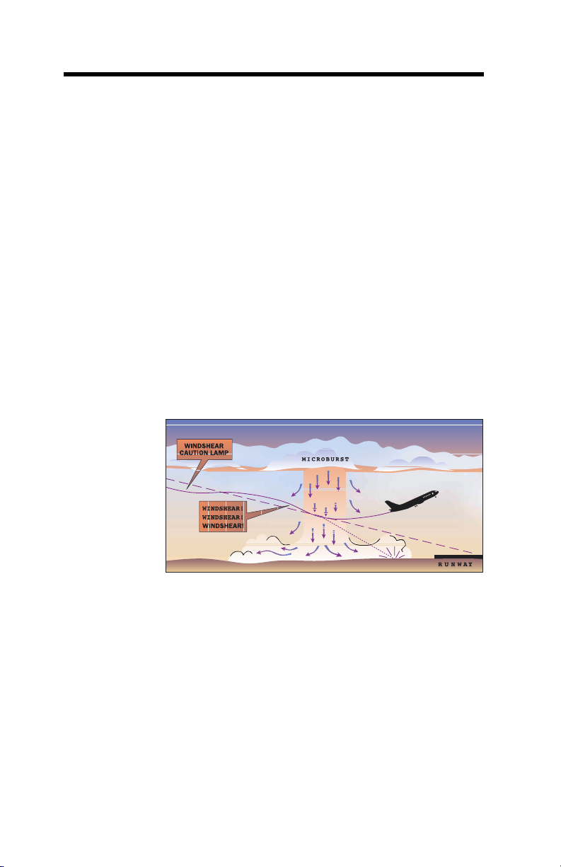
Mode 7 is designed to provide alerts if the aircraft encounters
windshear. Two alerting envelopes provide either a Windshear
Caution alert or a Windshear Warning alert each with distinctive
aural and visual indications to the flight crew.
EGPWS windshear is provided for certain (not all) aircraft types
and is a function of certain additionally required input signals
and enabled internal detection algorithms. These are
established during the initial installation and addressed in the
appropriate Airplane Flight Manual (AFM) or EGPWS Airplane
Flight Manual Supplement (AFMS).
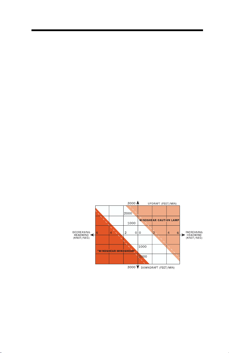
Windshear Caution alerts are given if an increasing headwind
(or decreasing tailwind) and/or a severe updraft exceed a
defined threshold. These are characteristic of conditions
preceding an encounter with a microburst.
A Windshear Caution if enabled results in illumination of
amber Windshear Caution lights and the aural message
“CAUTION, WINDSHEAR”. The lights remain on for as long as
the aircraft is exposed to conditions in excess of the caution alert
threshold. The Windshear Caution envelope is illustrated in the
figure below.
The Windshear Caution alerting can be disabled by EGPWS
program pin selection so that only Windshear Warning alerts
are provided.
060-4241-000 • Rev. D - March 2000
MK V & MK VII EGPWS Pilot Guide
25
Page 26
M
ODE
7
Continued
Windshear
Warning
Windshear
Caution
Windshear Warning alerts are given if a decreasing headwind
(or increasing tailwind) and/or a severe downdraft exceed a
defined threshold. These are characteristic of conditions
within or exiting an encounter with a microburst.
Windshear Warning results in illumination of red Windshear
Warning lights and an aural siren followed by the message
“WINDSHEAR, WINDSHEAR, WINDSHEAR”. The lights
remain on for as long as the aircraft is exposed to conditions in
excess of the warning alert threshold. The aural message will
not repeat unless another separate windshear event is
encountered. The threshold is adjusted as a function of
available climb performance, flight path angle, airspeeds
significantly different from normal approach speeds, and
unusual fluctuations in Static Air Temperature (typically
associated with the leading edge of a microburst). The
Windshear Warning envelope is illustrated in the figure shown
on page 23.
Mode 7 Windshear alerting is active under the following
conditions:
• During takeoff; from rotation until an altitude of 1500 feet
AGL is reached,
• During approach; From an altitude of 1500 feet down to
10 feet AGL,
• During a missed approach; until an altitude of 1500 feet
AGL is reached.
26 MK V & MK VII EGPWS Pilot Guide
060-4241-000 • Rev. D - March 2000
Page 27

ENHANCED FUNCTIONS:
Envelope
Modulation
Terrain
Clearance
Floor
Due to terrain features at or near certain specific airports
around the world, normal operations have resulted in nuisance
or missed alerts at these locations in the past. With the
introduction of accurate position information and a terrain and
airport database, it is possible to identify these areas and adjust
the normal alerting process to compensate for the condition.
The EGPWS Envelope Modulation feature provides improved
alert protection and expanded alerting margins at identified key
locations throughout the world. This feature is automatic and
requires no flight crew action.
Modes 4, 5, and 6 are expanded at certain locations to provide
alerting protection consistent with normal approaches. Modes
1, 2, and 4 are desensitized at other locations to prevent
nuisance alerts that result from unusual terrain or approach
procedures. In all cases, very specific information is used to
correlate the aircraft position and phase of flight prior to
modulating the envelopes.
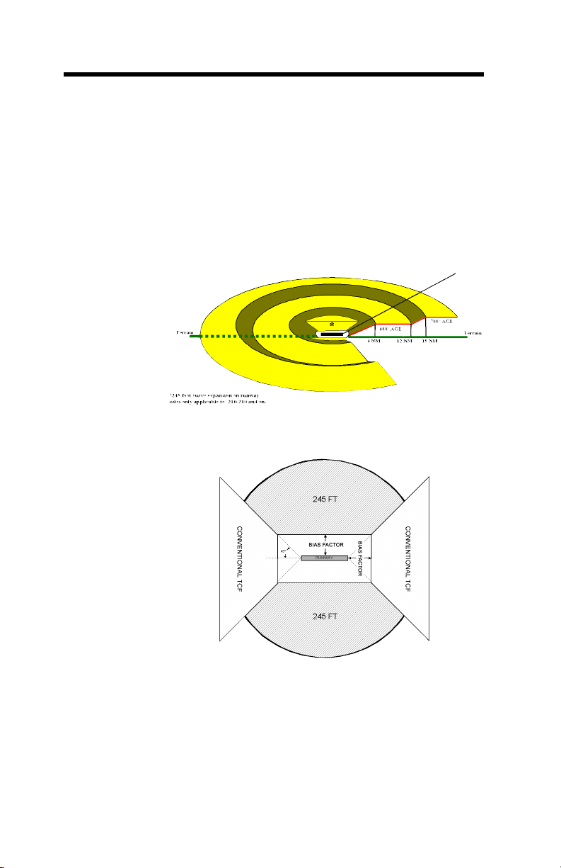
The Terrain Clearance Floor (TCF) function (enabled with
TAD) enhances the basic GPWS Modes by alerting the pilot
of descent below a defined “Terrain Clearance Floor”
regardless of the aircraft configuration. The TCF alert is a
function of the aircraft’s Radio Altitude and distance
(calculated from latitude/longitude position) relative to the
center of the nearest runway in the database (all hard surface
runways greater than 3500 feet in length). The TCF envelope is
defined for all runways as illustrated below and extends to
infinity, or until it meets the envelope of another runway. The
envelope bias factor is typically 1/2 to 2 nm and varies as a
function of position accuracy.
060-4241-000 • Rev. D - March 2000
MK V & MK VII EGPWS Pilot Guide
1/2 Runway Length
Envelope Bias Factor
(Minimum Elevation Number)
TCF Alert Envelope
4NM
12NM
400’
15NM
700’
30’
27
Page 28
Terrain
Clearance
Floor
Continued
In -210-210 and later versions, the TCF alert envelope
and Envelope Bias Factor are improved. The alert
envelope is limited to a minimum of 245 feet AGL
adjacent to the runway as illustrated in the following
diagrams. The Envelope Bias Factor is reduced (moved
closer to the runway) when higher accuracy aircraft
position and runway position information is available.
This is typically 1/3 to 1 nm providing greater protection
against landing short events.
Improved TCF Envelope
Improved TCF Envelope Plan View
Also in -210-210 and later versions, runway selection
logic is improved to better identify the destination
runway. Comprehensive aircraft position and navigation
information is used to evaluate proximity runways and
determine the most likely destination runway for all
alerting purposes.
28 MK V & MK VII EGPWS Pilot Guide
060-4241-000 • Rev. D - March 2000
Page 29
Runway
Field
Clearance
Floor
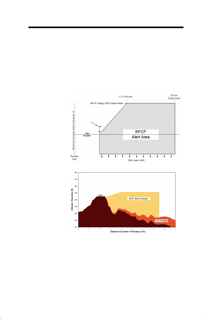
In -210-210 and later versions, a Runway Field
Clearance Floor feature is included. This is similar to
the TCF feature except that RFCF is based on the current
aircraft position and height above the destination
runway, using Geometric Altitude (in lieu of Radio
Altitude). This provides improved protection at
locations where the runway is significantly higher than
the surrounding terrain as illustrated below.
RFCF Alert Envelope
TCF and RFCF alerts result in illumination of the EGPWS
caution lights and the aural message “TOO LOW TERRAIN”.
The audio message is provided once when initial envelope
penetration occurs and again only for additional 20%
decreases in Radio Altitude. The EGPWS caution lights will
remain on until the TCF envelope is exited.
Terrain
Look Ahead
Alerting
060-4241-000 • Rev. D - March 2000
MK V & MK VII EGPWS Pilot Guide
Another enhancement provided by the internal terrain
database, is the ability to look ahead of the aircraft and detect
terrain or obstacle conflicts with greater alerting time.
29
Page 30

Terrain
Look
Ahead
Alerting
continued
This is accomplished (when enabled) based on aircraft position, flight path angle, track, and speed relative to the terrain
database image forward the aircraft.
Through sophisticated look ahead algorithms, both caution and
warning alerts are generated if terrain or an obstacle conflict
with “ribbons” projected forward of the aircraft (see following
illustration). These ribbons project down, forward, then up
from the aircraft with a width starting at 1/4 nm and extending
out at ± 3º laterally, more if turning. The look-down and up
angles are a function of the aircraft flight path angle, and the
look-down distance a function of the aircraft’s altitude with respect to the nearest or destination runway. This
relationship prevents undesired alerts when taking off or
landing. The look-ahead distance is a function of the aircraft’s
speed, and distance to the nearest runway.
A terrain conflict intruding into the caution ribbon activates
EGPWS caution lights and the aural message “CAUTION
TERRAIN, CAUTION TERRAIN” or “TERRAIN AHEAD,
TERRAIN AHEAD”. An obstacle conflict provides a “CAUTION
OBSTACLE, CAUTION OBSTACLE” or “OBSTACLE AHEAD, OBSTACLE AHEAD” message. The caution alert is given
typically 60 seconds ahead of the terrain/obstacle conflict and is
repeated every seven seconds as long as the conflict remains
within the caution area.
When the warning ribbon is intruded (typically 30 seconds
prior to the terrain/obstacle conflict), EGPWS warning lights activate and the aural message “TERRAIN, TERRAIN, PULL UP” or
“OBSTACLE, OBSTACLE, PULL UP” is enunciated with “PULL
UP” repeating continuously while the conflict is within the
warning area.
WARN
CAUTION
30 MK V & MK VII EGPWS Pilot Guide
060-4241-000 • Rev. D - March 2000
Page 31

Terrain
Look
Ahead
Alerting
continued
Terrain
Alerting
and Display
In -210-210 and later versions, the look-ahead alerting
algorithms are improved at higher airspeeds (about 300 knots
or greater). The look-ahead distance is designed to provide a
60-second warning alert for up to 8 nm look-ahead (as
opposed to 30-seconds or up to 4 nm).
The specific aural message provided is established during the
initial installation of the EGPWS as a function of whether or not
the terrain and obstacles features are enabled and the selected
audio menu (via program pin selection).
Refer to an applicable AFM or EGPWS AFMS for specific
application information or contact Honeywell for additional
information.
When a compatible Weather Radar, EFIS, or other display is
available and enabled, the EGPWS Terrain Alerting and Display
(TAD) feature provides an image of the surrounding terrain
represented in various colors and intensities.
There are two types of TAD displays depending on the options
selected. The original type provides a terrain image only when
the aircraft is 2000 feet or less above the terrain. A second type
called “Peaks” enhances the display characteristics to provide a
higher degree of terrain awareness independent of the
aircraft’s altitude (available for selected display types in
version -206-206 with additional displays added in later
versions). In either case, terrain and obstacles (if enabled)
forward of the aircraft are displayed. Obstacles are presented
on the cockpit display as terrain, employing the same
display-coloring scheme. TAD, Peaks and Obstacle functions
are enabled by EGPWS program pin selection.
NOTE: With respect to Non-Peaks or Peaks display, terrain and
or obstacle presentation is always based on (and scaled for) the
geographic area available for display. Consequently,
terrain and/or obstacles outside of the selected display range
and defined display sweep do not have any effect on the
displayed image.
060-4241-000 • Rev. D - March 2000
MK V & MK VII EGPWS Pilot Guide
31
Page 32
Non-Peaks
Display
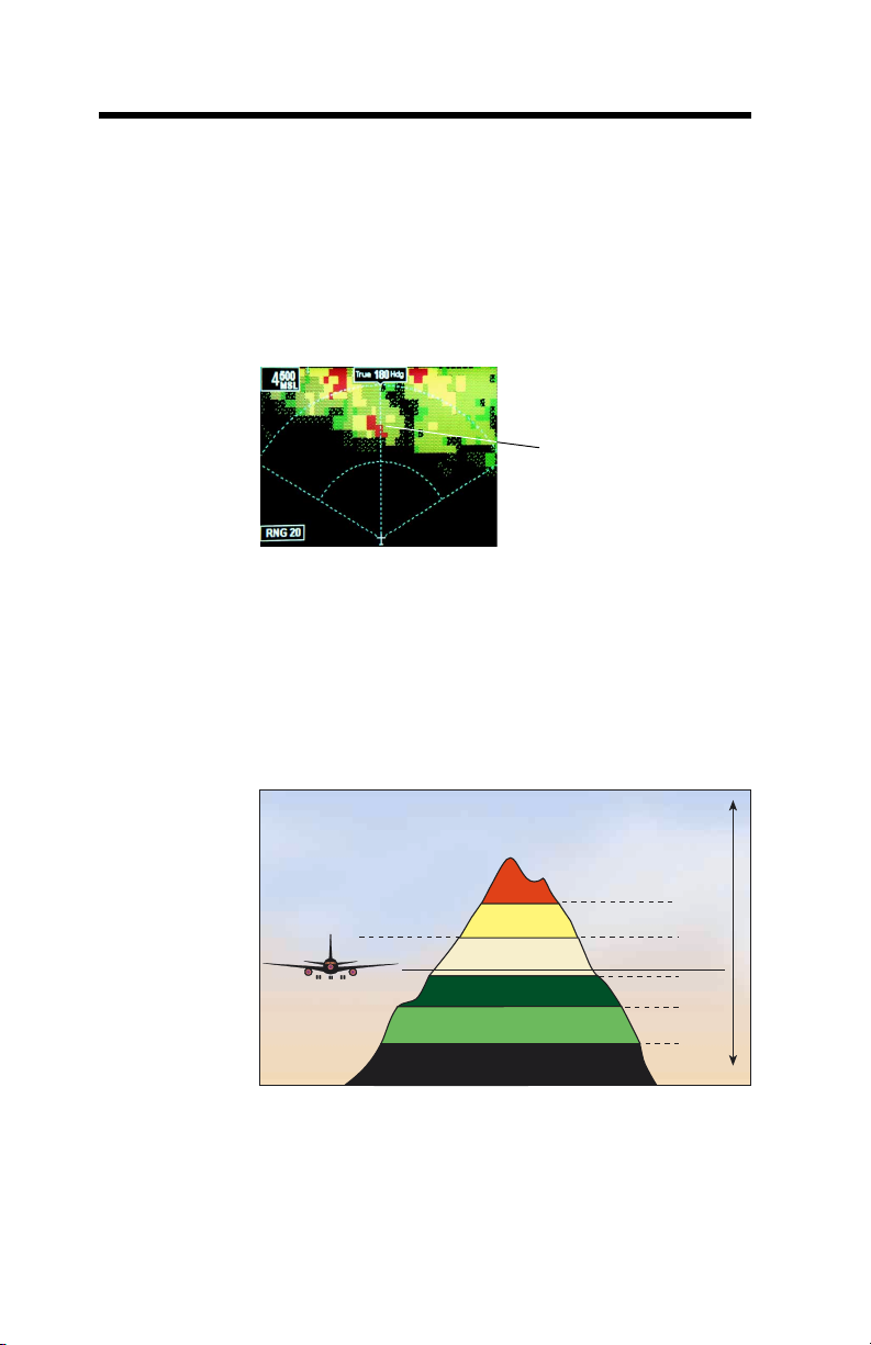
The Non-Peaks display provides a graphical plan-view image
of the surrounding terrain as varying density patterns of green,
yellow, and red as illustrated in the following graphics. The
selected display range is also indicated on the display, and an
indication that TAD is active is either indicated on the display
(i.e., “TERR”) or by an adjacent indicator.
TERRAIN IS SHOWN
IN SHADES OF GREEN,
YELLOW AND RED
Avidyne FlightMax 850 shown
Each specific color and intensity represents terrain (and
obstacles) below, at, or above the aircraft’s altitude based on the
aircraft’s position with respect to the terrain in the database. If
no terrain data is available in the terrain database, then this area
is displayed in a low-density magenta color. Terrain more than
2000 feet below the aircraft, or within 400 (vertical) feet of the
nearest runway elevation, is not displayed (black).
50% Red
50% Yellow
25% Yellow
50% Green
16% Green
Black
32 MK V & MK VII EGPWS Pilot Guide
Aircraft Elevation
060-4241-000 • Rev. D - March 2000
+2000’
+1000’
-
500
(Variable)
-1000’
-2000’
0
Page 33
Non-Peaks
Display
continued
60 Seconds from
projected impact
“Caution Terrain!”
Caution Terrain is
30 Seconds from
projected impact
“Terrain, Terrain,
Warning Terrain
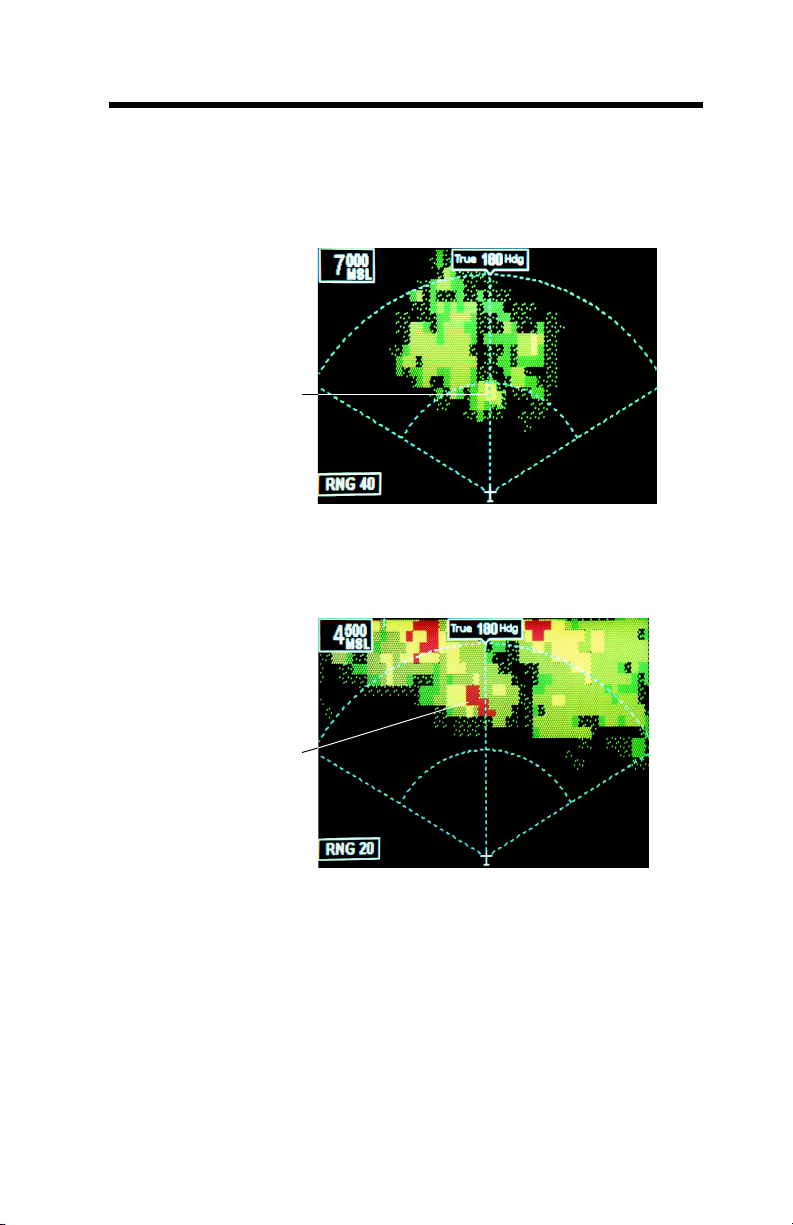
When a caution alert is triggered, the terrain (or obstacle) that
created the alert is changed to solid yellow (100% density) as
illustrated below.
solid Yellow
Avidyne FlightMax 850 shown
When a warning alert is triggered, the terrain (or obstacle) that
created the alert is changed to solid red (100% density) as
illustrated below.
–Pull Up!”
is Solid Red
NOTE: When a TAD caution or warning alert is active, the
display image (cells) surrounding the target are enlarged
(surrounding cells are illuminated). This allows a smaller
terrain or obstacle (e.g., a single tower) to be better seen on
the display.
The transition between green and yellow is below the aircraft in
order to account for altimetry and/or terrain/obstacle height
errors. Also, the transition altitudes between colors are biased
upward proportional to the descent rate when greater than
1000 feet per minute. This provides approximately a 30
second advance display of terrain.
060-4241-000 • Rev. D - March 2000
MK V & MK VII EGPWS Pilot Guide
Avidyne FlightMax 850 shown
33
Page 34

Non-Peaks
Display
continued
Essentially, pilots should note that any yellow or red painted
terrain is at, or above the aircraft’s altitude and appropriate
terrain clearance needs to be provided.
"Pop-Up" and
“AutoRange”
PEAKS
DISPLAY
Based on the display system used, there may be additional
terrain display features. These are defined as installation
options and allow for:
• Automatic display of terrain on the cockpit display (“TAD
pop-up”) in the event that a caution or warning alert is
triggered as described in Terrain Look Ahead Alerting. In
some cases, an active display mode must be selected first.
•“Auto-range” when Pop-up occurs. This provides for the automatic range presentation for terrain as defined for the
display system configuration (typically 10 nm). In this case,
if the terrain auto-range is different than the display system
selected range, the displayed range value on the cockpit display is flashed or changed color until the range is manually
reselected or terrain display is deselected.
Peaks Display has all the characteristics of the Non-Peaks
Display but with additional terrain display features for
enhanced situational awareness independent of the aircraft’s
altitude. The principle additions are:
• The digital display of the highest and lowest terrain/obstacle
elevations currently displayed,
• The display of additional solid or lower density color bands,
including the addition of the graphic representation of sea
level (0 feet MSL).
With Terrain Display selected on, digital values representing the
highest terrain/obstacle elevation and the elevation for the
bottom of the lowest color band are displayed. These are based
on the range selected (terrain in view)
The location of the digital values can vary somewhat for the
display used, but for this guide will be shown in the lower right
corner of the display. These elevations are expressed in
hundreds of feet above sea level (e.g., 125 is 12,500 feet MSL)
with the highest elevation on top and the lowest on the bottom.
However, in the event that there is no appreciable difference in
the terrain/obstacle elevations (flat terrain), only the highest
value is displayed. Additionally, the color of the elevation value
34 MK V & MK VII EGPWS Pilot Guide
060-4241-000 • Rev. D - March 2000
Page 35
PEAKS
DISPLAY
continued
is presented the same as the color of the terrain display
containing that elevation (i.e., red if the terrain/obstacle with
that elevation is depicted as red in the terrain plan view, yellow
if yellow, etc.).
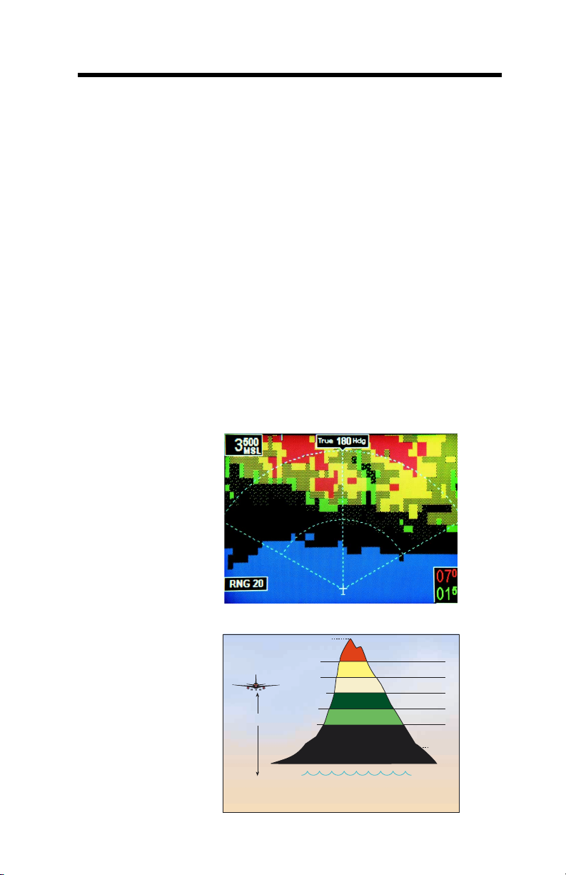
When the aircraft is 500 feet (250 with gear down) or less
above the terrain in view (yellow or red is displayed), the Peaks
color scheme is identical to the standard display, with the exception of the addition of sea level when supported by the
display.
Note: some displays do not support cyan (blue) and will not
display sea level in this case.
Note: Differences may exist between the highest terrain/
obstacle being displayed and the digital elevation value/
color of the "Peaks" numbers at or near the top and sides
of the display.
The following illustrate the Peaks display at a low relative
altitude.
060-4241-000 • Rev. D - March 2000
MK V & MK VII EGPWS Pilot Guide
Avidyne FlightMax 850 shown
(Maximum Elevation Number)
Ref Altitude + 2000
Ref Altitude + 1000
Ref Altitude -250/-500
Ref Altitude -1000
Reference
Altitude
Ref Altitude -2000
Reference Altitude is projected down from actual aircraft altitude to pr
display of terrain when descending more than 1000 FPM.
Terrain is not shown if it is below the lowest band and/or is within 400 feet of the runway
elevation nearest the aircraft. Sea level water is displayed if supported by the display.
(Minimum Elevation Number)
ovide a 30 second advance
50% Red
50% Yellow
25% Yellow
50% Green
16% Green
Black
CyanSea Level
35
Page 36
PEAKS
DISPLAY
continued
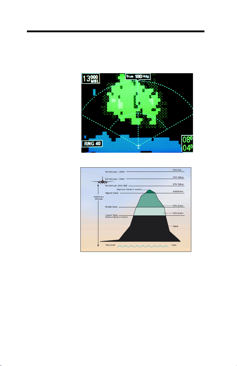
The following illustrate the Peaks display at a high relative
altitude.
Avidyne FlightMax 850 shown
36 MK V & MK VII EGPWS Pilot Guide
060-4241-000 • Rev. D - March 2000
Page 37

PEAKS
DISPLAY
continued
When the aircraft is greater than 500 feet (250 with gear down)
above the terrain in view (no yellow or red displayed),
additional (green) color bands are presented. These added
bands are computed and displayed as a function of the highest
and lowest elevations in view.
The following table indicates the TAD colors and elevations
(Non-Peaks and Peaks).
Color Indication
Solid Red Terrain/Obstacle Threat Area – Warning.
Solid Yellow Terrain/Obstacle Threat Area – Caution.
50% Red Fill Terrain/Obstacle that is more than 2000 feet
above aircraft altitude.
50% Yellow Fill Terrain/Obstacle that is between 1000 and 2000
feet above aircraft altitude.
25% Yellow Fill Terrain/Obstacle that is 500 (250 with gear
down) feet below to 1000 feet above aircraft altitude.
Solid Green Shown only when no Red or Yellow terrain
(Peaks only) /Obstacle areas are within range on the display.
Highest terrain/Obstacle not within 500 (250
with gear down) feet of aircraft altitude.
50% Green Fill Terrain/Obstacle that is 500 (250 with gear
down) feet below to 1000 below aircraft altitude.
(Peaks only) Terrain/Obstacle that is the middle elevation
band when there is no Red or Yellow terrain areas
within range on the display.
16% Green Fill Terrain/Obstacle that is 1000 to 2000 feet below
aircraft altitude.
(Peaks only) Terrain/Obstacle that is the lower elevation band
when there is no Red or Yellow terrain areas
within range on the display.
Black No significant terrain/Obstacle.
16% Cyan Fill Water at sea level elevation (0 feet MSL).
(Peaks only)
Magenta Fill Unknown terrain. No terrain data in the data-
base for the magenta area shown.
Note: magenta may be displayed at or near the South and North Poles
dependent upon the airplane flight path and location.
060-4241-000 • Rev. D - March 2000
MK V & MK VII EGPWS Pilot Guide
37
Page 38

TCF/TAD
INOP and
INHIBIT
Geometric
Altitude
The EGPWS TCF and TAD functions are available when all
required data is present and acceptable. Aircraft position and
numerous other parameters are monitored and verified for
adequacy in order to perform these functions. If determined
invalid or unavailable, the system will display Terrain
inoperative or unavailable annunciations and discontinue the
terrain display if active.
TAD/TCF functions may be inhibited by manual selection of a
cockpit Terrain Inhibit switch. Neither loss nor inhibiting TAD/
TCF effects the basic GPWS functions (modes 1-7).
If Peaks affects is not active and TAD becomes unavailable
due to position error, terrain inoperative or unavailable is not
indicated if the aircraft is greater than 8000 feet above the
highest terrain or obstacle within a 320nm radius. If
indicated below the 8000 foot threshold, it is extinguished
when the aircraft climbs above, and is again displayed once
the aircraft descends below the 8000 foot threshold. This
eliminates potentially longterm illumination of the condition
during the high enroute phase of flight.
Based on GPS altitude, geometric altitude is a computed
pseudo-barometric altitude (Above Sea Level - ASL) designed
to reduce or eliminate errors potentially induced in Corrected
Barometric Altitude by temperature extremes, non-standard
pressure altitude conditions, and altimeter miss-sets. This
ensures an optimal EGPWS Terrain Alerting and Display
capability. Geometric Altitude also allows EGPWS operations in
QFE environments without custom inputs or special
operational proceedures.
Geometric Altitude requires GPS Altitude input with its associated Vertical Figure Of Merit (VFOM) and
Receiver Autonomous Integrity Monitoring (RAIM) failure
indication, standard (uncorrected) altitude, Radio Altitude,
Ground Speed, Roll Angle, and aircraft position (Latitude and
Longitude). Additionally, corrected Barometric Altitude, Static
Air Temperature (SAT), GPS mode, and the number of
satellites tracked are used if available.
The Geometric Altitude is computed by blending a calculated
Non-Standard Altitude, Runway Calibrated Altitude
(determined during takeoff), GPS Calibrated Altitude, Radio
38 MK V & MK VII EGPWS Pilot Guide
060-4241-000 • Rev. D - March 2000
Page 39

Geometric
Altitude
continued
Weather
Radar
Auto-Tilt
Aural
Message
Priority
Altitude Calibrated Altitude (determined during approach), and
Barometric Altitude (if available). Estimates of the VFOM for
each of these are determined and applied in order to determine
its weight in the final altitude. The blending algorithm gives the
most weight to altitudes with a higher estimated accuracy,
reducing the effect of less accurate altitudes. Each component
altitude is also checked for reasonableness using a window
monitor computed from GPS Altitude and its VFOM. Altitudes
that are invalid, not available, or fall outside the reasonableness
window are not included in the final Geometric Altitude value.
The Geometric Altitude algorithm is designed to allow continued
operation when one or more of the altitude components are not
available. If all component altitudes are invalid or unreasonable, the GPS Altitude is used directly. If GPS Altitude fails or is
not present, then the EGPWS reverts to using Corrected
Barometric Altitude alone.
The Geometric Altitude function is fully automatic and requires
no pilot action other than the proper setting of Corrected
Barometric Altitude on the Altimeter.
In -210-210 and later versions, the EGPWC computes a
optimum Weather Radar tilt angle based on the aircraft altitude
(ASL) and the terrain elevation ahead of the aircraft. This is
output and available to a compatible Weather Radar system so
that the tilt angle may be automatically set for optimum
operation.
Two or more messages may be activated simultaneously, so a
message priority has been established. The following table
reflects the priority for these message callouts. Messages at the
top of the list will start before or immediately override a lower
priority message even if it is already in progress.
060-4241-000 • Rev. D - March 2000
MK V & MK VII EGPWS Pilot Guide
39
Page 40

MESSAGE MODE
“Windshear, Windshear, Windshear”
h, i, k
“Pull Up”
...............................................................................................................................................
d, j
..............................................................................................
1, 2, TA
“Terrain, Terrain” ................................................................................. 2, TA
c
“Obstacle, Obstacle”
......................................................................................................................................
“Terrain” ................................................................................................... 2
a, c
“Minimums”
“Caution Terrain, Caution Terrain”
“Caution Obstacle, Caution Obstacle”
........................................................................................................................................................
c, f
.................................................................................................
c, g
..........................................................................................
“Too Low Terrain” .............................................................................. 4, TCF
c
Altitude Callouts
....................................................................................................................................................
“Speed Brake, Speed Brake” c..................................................................... 6
“Too Low Gear” ....................................................................................... 4A
“Too Low Flaps” ....................................................................................... 4B
“Sink Rate, Sink Rate” ............................................................................... 1
“Don’t Sink, Don’t Sink” ............................................................................ 3
“Glideslope” .............................................................................................. 5
“Approaching Minimums”
“Bank Angle, Bank Angle”
“Caution Windshear”
b, c
.......................................................................................................................
c
...........................................................................................................................
c, d, e
................................................................................................................................
“Autopilot” c............................................................................................... 6
“Flaps, Flaps” c.......................................................................................... 6
Notes:
a) May also be “Minimums, Minimums”, "Decision Height" or “Decide”.
b) May also be “Approaching Decision Height”, “Fifty Above”, “Plus Hundred”.
c) Message is dependent on aircraft type or option selected.
d) Windshear detection alerts provided for some aircraft types.
e) Caution alert if not disabled.
f) May also be “Terrain Ahead, Terrain Ahead”.
g) May also be “Obstacle Ahead, Obstacle Ahead”
h) May also be “Terrain Ahead Pull Up”
i) May also be “Obstacle Ahead Pull Up”
j) May be preceded by siren.
k) May be proceded by “Whoop, Whoop”
TA=Terrain Look-Ahead Alert
TCF=Terrain Clearance Floor
7
TA
6
TA
TA
6
6
6
7
40 MK V & MK VII EGPWS Pilot Guide
060-4241-000 • Rev. D - March 2000
Page 41
System
Inputs
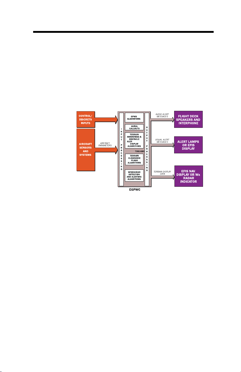
The EGPWS uses various input signals from other on-board
systems. The full compliment of these other systems is
dependent on the EGPWS configuration and options selected.
Systems providing Altitude, Airspeed, Attitude, Glideslope, and
position are required for basic and enhanced functions.
Accelerations, Angle-of-Attack (AOA), and Flap position is
required for Windshear. Inputs are also required for discrete
signal and control input.
Air Data
The EGPWS utilizes signals from the following systems:
Uncorrected and corrected Barometric Altitude, Altitude rate,
Computed Airspeed, True Airspeed, and Static Air Temperature
are provided by Air Data system.
Radio
Altitude
Radio Altitude is provided by a Radio Altimeter system.
Decision Height or Decision Height Altitude is provided by a
Radio Altimeter system or ancillary system.
In -210-210 and later versions, the EGPWC performs Radio
Altitude reasonableness checks based on the Computed
Te rrain Clearance (pseudo-radio altitude). Computed Terrain
Clearance is computed by subtracting the elevation of the
(database) terrain below the aircraft from Geometric Altitude
(ASL). Radio Altitude is considered unreasonable when it
indicates a terrain clearance that is less than the Computed
Te rrain Clearance by more than 2000 feet. For example, if the
Computed Terrain Clearance is 10,000 feet and the Radio
Altitude is any value (0-2500) then the Radio Altitude is
considered unreasonable. This is only performed if TAD is
enabled, high integrity terrain and position data is available
(based on GPS/Geometric Altitude), and the Computed Terrain
Clearance is greater than 4000 feet.
060-4241-000 • Rev. D - March 2000
MK V & MK VII EGPWS Pilot Guide
41
Page 42

Radio
Altitude
continued
This feature reduces the potential for nuisance alerts caused by
false tracking of the Radio Altimeter.
FMS, IRS,
AHRS, Accelerometer
Global
Positioning
System (GPS)
VHF Nav
Reciever
Terrain Display System
AOA Vane or
Stall Warning
Discretes
Pitch and Roll Attitude, Latitude and Longitude Position, Body
Normal and Longitudinal Accelerations, Magnetic and True
Track Angles, Magnetic and True Heading, Inertial Altitude,
Groundspeed, and mode.
Latitude and Longitude Position, True Track Angle, GPS
Altitude, Groundspeed, Horizontal and Vertical Figure of Merit
(VFOM/HFOM), Horizontal and Vertical Dilution of Precision
(HDOP/VDOP), Horizontal Integrity Limit (HIL), and sensor
status.
Glideslope, Localizer, ILS Tuned, Selected Runway
Heading.
Display range, and if available the Hazard Bus from a Predictive
Windshear System (PWS). If EFIS, the EFIS display mode is
used in some configurations.
AOA, Stick Shaker Margin.
Discrete inputs are used for system configuration, signal/status
input, and control input functions.
EGPWS program pins are utilized to tell the system the type of
aircraft and interface that it is in. These are defined and
established during the EGPWS installation. EGPWS output
functions are consequently the result of the program pin state
read each time the EGPWS is powered on.
Signal/status discretes include signals such as Decision Height,
Landing Flaps selected or Flap Position discretes, Landing Gear
selected, Terrain Display Range, and status discretes such as
Glideslope Valid, Localizer Valid, Radio Altitude Valid associated
with analog signal inputs.
Control discretes control EGPWS functions. These include
EGPWS Test, Glideslope Cancel, Glideslope Inhibit or Glideslope
Backcourse, Terrain (display) select, Terrain Inhibit, Flap
Over-ride, Audio Inhibit, Altitude Callout Enable, Steep
Approach Enable, and ILS Tuned discretes.
42 MK V & MK VII EGPWS Pilot Guide
060-4241-000 • Rev. D - March 2000
Page 43

System
Outputs
Options
The EGPWS provides both audio and visual outputs.
Audio outputs are provided as specific alert phrases, and
altitude callouts or tones provided by an EGPWS speaker and
via the cockpit Interphone system for headset usage. Several
audio output levels are available. They are established during
the installation of the EGPWS. These EGPWS audio outputs can
be inhibited by other systems having higher priority (i.e.,
windshear) or cockpit switches in some cases. The EGPWS
also has the ability to inhibit other system audio outputs such
as TCAS.
Visual outputs provide discrete alert and status annunciations,
and display terrain video when a compatible display system is
available and enabled. The discrete visual alerts coincide with
audio caution and warning alerts to achieve an optimum
terrain alerting capability. Status annunciations provide
information to the flight crew about the status of the EGPWS
(e.g., GPWS INOP) or activation of selected functions. Terrain
video is generated by the EGPWC based on the aircraft’s current
position relative to the surrounding terrain. This video is
presented to a Weather Radar indicator, EFIS display, or a
dedicated display unit.
The EGPWC uses program pin discrete inputs to define the installation configuration and option selection. The EGPWS has
been designed for maximum flexibility while being tailored to
specific aircraft equipment, sensors, and displays. The following list summarizes available Operator options (excluding
sensor and equipment configuration options):
• Flashing Lamps – When selected causes alert annunciators
to flash when active.
•TAD and TCF Disable – Suppresses all TAD and TCF alerting
and display functions.
• Altitude Callouts – Selects desired altitude callouts from a
menu of options.
• Audio Output Level – Selects desired audio output level
High, Medium, or Low.
• Alternate Mode 6 Volume – Selects reduced Mode 6
volume (-3 dB).
060-4241-000 • Rev. D - March 2000
MK V & MK VII EGPWS Pilot Guide
43
Page 44

Options
continued
• Obstacle Awareness Enabled – Enables obstacle alerting and
display.
•TAD Alternate Pop Up – If TRUE, disables automatic terrain
display when TAD or Obstacle alert is active.
•Mode 6 Volume Reduction – Selects reduced Mode 6 volume (-6 dB).
•Smart Callout Enable – Enables the 500-foot smart callout.
“Five Hundred” is called out at 500 feet Radio Altitude during non-precision approaches, if 500’ is part of the altitude
callout option selected. This callout is not given on precision
approaches.
• Bank Angle Enable – Enables Bank Angle alerts.
•Windshear Caution Voice Disable – Disables Windshear Caution voice alerts providing visual alerts only.
• Audio Declutter Disable – Disables the Audio Declutter function so that audio alerts are constant.
• Audio Alerting Voice Select – Selects the type(s) of voice that
are used for audio alerts.
• Lamp Format – One of two lamp formats are available.
• Lamp Format 1 provides only Mode 5 “Glideslope” alerts
to the caution (amber) lamp output and all other alerts
(except Windshear and Mode 6 callouts) to the warning
(red) lamp output.
• Lamp Format 2 provides all “Pull Up” warning alerts to
the warning (red) lamp output and all caution alerts to
the caution (amber) lamp output (Recommended).
NOTE: Windshear annunciations are provided by separate outputs and indications and is not affected by lamp format. Mode 6
advisories do not effect any annunciation and are not affected by
lamp format.
•Peaks Enable – Adds additional density patterns and level
thresholds to the Standard Display Mode, allowing display of highest and lowest terrain/obstacle to increase
situational awarness.
44 MK V & MK VII EGPWS Pilot Guide
060-4241-000 • Rev. D - March 2000
Page 45

Options
continued
Additional input discretes are used to control or define EGPWS
operations:
• EGPWS Self-Test – Cockpit switch initiates EGPWS Self-Test
on the ground. Typically part of EGPWS warning (red) lamp.
• Glideslope Cancel – Cockpit switch cancels Mode 5
Glideslope alerting. Typically part of EGPWS caution (amber) lamp.
• Glideslope Inhibit – Inhibits Mode 5 Glideslope alerting.
Normally used for backcourse approaches.
• Altitude Callout Enable – Enables Mode 6 Callouts.
•Mode 6 Low Volume – Reduces Mode 6 volume (an additional) 6 dB. This is typically hardwired or connected to an
external switch.
•TAD and TCF Inhibit – Cockpit switch to disable all TAD and
TCF functions.
• Audio Inhibit – disables all EGPWS audio outputs.
• Steep Approach Enable – Enables Steep Approach (Mode 1
Excessive Descent Rate) alerts biasing.
• Steep Approach Select – Selects (activates) Steep Approach
(Mode 1 Excessive Descent Rate) alerts biasing to reduce
nuisance alerts.
• Flap Over-Ride – Cockpit switch to select landing flaps when
not in the landing flap configuration.
• PLI Select/Deselect – Used for displaying or deselecting the
display of EGPWS derived Pitch Limit Indicator (PLI) signals
when a Windshear warning occurs.
For additional options information contact Honeywell.
060-4241-000 • Rev. D - March 2000
MK V & MK VII EGPWS Pilot Guide
45
Page 46

S
ECTION
3
Operational Procedures
System Constraints ............................................................................. 45
System Activation................................................................................ 46
EGPWS Self Test ...................................................................................47
Normal Procedures............................................................................. 50
Caution Alerts ................................................................................ 51
Warning Alerts ............................................................................... 51
Glideslope Alerts............................................................................ 51
Advisory Callouts ............................................................................ 52
Windshear Caution .........................................................................52
Windshear Warning ........................................................................ 52
Abnormal Procedures.......................................................................... 53
Emergency Procedures........................................................................ 54
46 MK V & MK VII EGPWS Pilot Guide
060-4241-000 • Rev. D - March 2000
Page 47

System
Constraints
System constraints for the EGPWS are:
• If terrain data is unavailable for a particular area, then
Te rrain and Obstacle alerting and display is not available for
that area and the affected display area is colored MAGENTA.
• The display of terrain and obstacle information is intended
to serve as a situational awareness tool. It does not provide
the accuracy and/or fidelity to be the sole source for
deciding terrain or obstacle avoidance. Navigation must not
be predicated upon the use of the EGPWS terrain/Obstacle
display.
• If there is no source of aircraft position data meeting the
accuracy requirements for the TAD and TCF functions, then
these enhanced functions are automatically inhibited with a
resultant Terrain inoperative or unavailable indication.
•TAD/TCF functions should be manually inhibited within 15
nm on approach to an airport that is not in the airport
database to avoid unwanted alerts.
•TAD/TCF functions should be manually inhibited during
QFE operations if GPS data is unavailable or inoperative.
•TAD/TCF functions should be manually inhibited for
ditching or other off-airport landings.
•When the TAD/TCF functions are inhibited and the EGPWS
is otherwise functional, the EGPWS reverts to providing
basic GPWS functions (Modes 1 to 6 and Windshear). In
this state, the EGPWS may give little or no advance warning
time for flight into precipitous terrain where there are few or
no preceding obstructions. This particularly applies if:
• The aircraft is in the landing configuration.
• The aircraft is in a stabilized descent at a
normal approach descent rate.
• There is no ILS GLideslope signal being recieved by the
EGPWS (not tuned, not available, or inoperative).
•Terrain clearance or descent rates that are not compatible
with required minimum regulatory standards for Ground
Proximity Warning equipment may cause unwanted alerts.
• If enabled, the EGPWS uses onboard measurement of air
mass parameters and aircraft acceleration for detection of
windshear. This is a reactive system and cannot predict
windshear, which may be ahead of the aircraft.
060-4241-000 • Rev. D - March 2000
MK V & MK VII EGPWS Pilot Guide
47
Page 48

System
Constraints
continued
• The EGPWS terrain/obstacle database includes
cataloged human-made obstructions 100 feet high or
greater within North America and portions of the Caribbean
(expanding). The database is not all-inclusive and newer,
smaller, or unknown obstructions could be encountered.
Refer to an appropriate AFM or EGPWS AFMS for specific
system limitations and procedures.
System
Activation
The EGPWS is fully active when the following systems are
powered and functioning normally:
• EGPWS
•Radio Altimeter
• Air Data
• ILS or Glideslope Receiver
• IRS, AHRS, VG (attitude)
• GPS, FMS, or IRS (position)
• Landing gear
• Landing flaps
• Stall warning or AOA (windshear only)
•Weather Radar, EFIS, or a dedicated terrain display
(if terrain/obstacle display enabled)
In the event that required data for a particular function is not
available, then that function is automatically inhibited and
annunciated (e.g. if position data is not available or determined
unacceptable, TAD and TCF is inhibited, any active terrain
display is removed, and “TERR INOP”, “TERR UNAVAIL” (or
equivalent) is indicated).
Some installations utilize redundant systems so that if the
primary source of data fails, the EGPWS continues on the
secondary source.
48 MK V & MK VII EGPWS Pilot Guide
060-4241-000 • Rev. D - March 2000
Page 49

System
Activation
continued
EGPWS status annunciations are provided for GPWS
inoperative (mode 1-6 functions), Terrain inoperative (TAD/TCF
functions), and windshear inoperative.
Refer to an appropriate AFM or EGPWS AFMS for specific system
and status requirements.
EGPWS
Self-Test
The EGPWS provides a Self-Test capability for verifying and
indicating intended functions. This Self-Test capability consists
of six levels to aid in testing and troubleshooting the EGPWS.
These six levels are:
Level 1 – Go / No Go Test provides an overview of the current
operational functions and an indication of their
status.
Level 2 – Current Faults provides a list of the internal and ex-
ternal faults currently detected by the EGPWC.
Level 3 – EGPWS Configuration indicates the current
configuration by listing the EGPWS hardware,
software, databases, and program pin inputs
detected by the EGPWC.
Level 4 - Fault History provides an historical record of the in-
ternal and external faults detected by the EGPWC.
Level 5 - Warning History provides an historical record of the
alerts given by the EGPWS.
Level 6 - Discrete Test provides audible indication of any
change to a discrete input state.
A level 1 Go/No Go Test is normally performed by flight crews as
part of preflight checks. All other levels are typically used for
installation checkout and maintenance operations.
060-4241-000 • Rev. D - March 2000
MK V & MK VII EGPWS Pilot Guide
49
Page 50

EGPWS
Self-Test
continued
level 1 Self Test is used to verify proper operation of the EGPWS
on the ground as follows:
1. Ensure that adequate aircraft power is available and the
EGPWS and associated systems are powered.
2. Ensure that any EGPWS inhibiting switches are in the
normal (non-inhibiting) position.
3. Verify that EGPWS inoperative annunciations are
extinguished. If an inoperative annunciation is indicated,
perform the EGPWS Self-Test (below) and then seek
corrective action if the inoperative condition persists.
4. If a terrain display is enabled, select terrain to be displayed.
5. Momentarily depress the EGPWS Self-Test switch.
When a Self-Test is initiated, the EGPWC first checks for any
configuration (installation or database) errors. If any are
detected it is audibly enunciated and the test is terminated. If
none detected, the test continues through a sequence resulting
in turning on and off all system annunciators, enunciating
specific audio messages, and if enabled, displaying a video test
pattern on the terrain display (see illustration below). Any
functions determined inoperative are also enunciated (e.g.,
“GLIDESLOPE INOP”). The Self-Test terminates automatically
at its conclusion.
The following is a description of the expected results of a typical
level 1 Self-Test. Actual annunciation nomenclature and
sequence may differ depending on the installation.
• GPWS INOP, W/S INOP, and TERR INOP annunciators turn
on.
•Amber caution (“BELOW G/S” or “GPWS”) annunciators
turn on.
• “GLIDESLOPE” is announced over speaker.
•Amber annunciators turn off.
• G/S CANCEL annunciators turn on (if installed).
50 MK V & MK VII EGPWS Pilot Guide
060-4241-000 • Rev. D - March 2000
Page 51

EGPWS
Self-Test
continued
• G/S CANCEL annunciators turn off.
• Red warning (“PULL UP” or “GPWS”) annunciators turn
on.
•“PULL UP” is announced over speaker.
• Red warning annunciators turn off.
• Red Windshear warning annunciators turn on.
• (Siren) “WINDSHEAR, WINDSHEAR, WINDSHEAR” is
announced over speaker.
• Red Windshear warning annunciators turn off.
•Amber Windshear caution annunciators turn on (if
installed and enabled).
•Amber Windshear caution annunciators turn off.
• Red warning (“PULL UP” or “GPWS”) annunciators turn
on.
• “TERRAIN, TERRAIN, PULL UP” is announced over speaker.
•Terrain test pattern is displayed (see below - Non Peaks
Shown).
• Red warning annunciators turn off.
• GPWS INOP, W/S INOP, and TERR INOP annunciators turn
•Terrain test pattern is turned off.
6. Verify expected indications and enunciations during test,
060-4241-000 • Rev. D - March 2000
MK V & MK VII EGPWS Pilot Guide
Avidyne FlightMax 850 shown
off.
repeating as necessary noting any erroneous conditions.
51
Page 52

A successful test is accomplished if all expected indications are
observed and no inoperative functions or display anomalies are
indicated or observed.
For more specific information, refer to an applicable AFM or
EGPWS AFMS, or contact Honeywell.
Normal
Procedures
The EGPWS provides visual and/or audio alerts for detected:
• potentially dangerous terrain conditions (modes 1 – 4, TCF,
TAD),
• below glideslope conditions (mode 5),
• descent below predefined altitudes or excessive bank angle
(mode 6),
•severe windshear conditions (mode 7)
These consist of warning, caution, and advisory alerts based on the
detection alert threshold penetration. The following list identifies
the various alerts by type and mode:
ALERT WARN CAUT. ADV.
(SIREN) “WINDSHEAR (3x)” 7
Any “PULL UP” 1,2,TA
“CAUTION WINDSHEAR” 7
“TERRAIN, TERRAIN” 2, TA
“OBSTACLE, OBSTACLE” TA
“TERRAIN” 2
“APPROACHING MINIMUMS” 6
“MINIMUMS” 6
“CAUTION TERRAIN” TA
“CAUTION OBSTACLE” TA
“TOO LOW TERRAIN” 4, TCF
“TOO LOW GEAR or FLAPS” 4
Altitude callouts 6
“SINK RATE” 1
“DON’T SINK” 3
“GLIDESLOPE” 5
“BANK ANGLE” 6
NOTE: Visual and audio indications may vary and procedures provided are
representative. Refer to an applicable AFM or EGPWS AFMS for specific
implementation.
52 MK V & MK VII EGPWS Pilot Guide
060-4241-000 • Rev. D - March 2000
Page 53

Caution
Alerts
Warning
Alerts
Glideslope
Alerts
Recommended response to EGPWS alerts are as follows:
1. Stop any descent and climb as necessary to
eliminate the alert. Analyze all available instruments and
information to determine best course of action.
2. Advise ATC of situation as necessary.
1. Aggressively position throttles for maximum rated thrust.
Apply maximum available power as determined by
emergency need. The pilot not flying (if applicable) should
set power and ensure that TO/GA power and modes are set.
2. If engaged, disengage the autopilot and smoothly but
aggressively increase pitch toward “stick shaker” or Pitch
Limit Indicators (PLI) to obtain maximum climb
performance.
3. Continue climbing until the warning is eliminated and safe
flight is assured.
4. Advise ATC of situation.
NOTE: Climbing is the only recommended response unless
operating in visual conditions and/or pilot determines, based
on all available information, that turning in addition to the
climbing is the safest course of action. Follow established
operating procedures.
NOTE: Navigation must not be based on the use of the Terrain
Awareness and Alerting Display (TAD).
Below Glideslope alerts consist of “soft” and “hard” alerts
based on the degree of glideslope deviation and altitude.
Respond to these alerts as necessary to correct the aircraft’s
flightpath back to the Glideslope centerline or perform a
missed approach.
060-4241-000 • Rev. D - March 2000
MK V & MK VII EGPWS Pilot Guide
53
Page 54

Advisory
Callouts
Windshear
Caution
Windshear
Warning
Advisory callouts being advisory in nature are used to
announce an event or condition (e.g., “Minimums”).
Response to these callouts should be in accordance with
standard operating procedures.
This alert generally occurs due to increasing performance
windshear conditions (i.e., increasing headwind, decreasing
tailwind, and/or updraft). This alert is generally considered
advisory in that the crew response is to be alert to the
possibility of subsequent significant airspeed loss and down
draft conditions. Coupled with other weather factors, the
Windshear Caution should be considered in determining the
advisability of performing a go-around.
Wind and gust allowances should be added to the approach
speed, increasing thrust if necessary. It may be necessary to
disengage autopilot or auto-throttle. Avoid getting low on the
approach glidepath or reducing the throttles to idle.
When a Windshear warning occurs, the following procedures
should be followed:
1. Immediately initiate the Windshear escape maneuver in
accordance with established Windshear procedures.
2. Aggressively apply maximum rated thrust, disengage
autopilot and/or auto-throttle if necessary.
3. Rotate smoothly to the go-around/take-off pitch attitude,
allowing airspeed to decrease if necessary. Maintain wings
level. Do not retract flaps or landing gear.
4. If the aircraft continues to descend, increase pitch attitude
smoothly and in small increments, bleeding air speed as
necessary to stop descent. Use Stall Warning onset (stick
shaker) as the upper limit of pitch attitude.
5. Maintain escape attitude and thrust and delay retracting
flaps or landing gear until safe climb-out is assured.
NOTE: Engine overboost should be avoided unless the
airplane continues to descend and airplane safety is in doubt.
54 MK V & MK VII EGPWS Pilot Guide
060-4241-000 • Rev. D - March 2000
Page 55

Windshear
Warning
continued
Abnormal
Procedures
Mode 1
Excessive
Descent
Rates
Mode 2
Excessive
Closure to
Terrain
Mode 4
Unsafe
Terrain
Clearance
Mode 5
Descent
Below
Glideslope
If overboost is required, adjust throttles back to maximum
rated thrust as soon as safety has been assured.
Overboosting engines while at high angle of attack near
airplane stall may cause engine stall, surge, or flameout.
Maintain escape attitude and thrust and delay retracting flaps
or landing gear until safe climb-out is assured.
Partial system deactivation or compensation can be
accomplished for abnormal procedures as follows:
If steep approaches are to be performed (4º or greater) EGPWS
STEEP APPROACH should be enabled and selected for these
operations. This may be accomplished automatically by
on-board systems or manually selected by a cockpit switch.
When active, Mode 1 alerts are desensitized to compensate for
normally higher descent rates for these types of operation,
eliminating related unwanted alerts. If implemented with a
cockpit switch, this requires manual deactivation.
When required to operate in close proximity to terrain (less
than 2500’ above), Mode 2 alerts can be desensitize or
overridden by activating the FLAP OVER-RIDE switch to
eliminate related unwanted alerts. This requires manual
deactivation.
Mode 4 alerts can be reduced by activation of the FLAP
OVER-RIDE switch. This is generally recommended when
performing approaches with less than landing flaps selected.
This requires manual deactivation.
Mode 5 Glideslope alerts can be manually canceled when
below 2000 feet Radio Altitude (Standard G/S Cancel) by
pressing the G/S Cancel switch (commonly part of the amber
caution annunciators “BELOW G/S” or “GPWS”). This is
typically selected when an unreliable Glideslope is expected or
when maneuvering is required during ILS final approach. The
G/S Cancel is automatically reset following landing or if the
aircraft climbs above the 2000 feet.
060-4241-000 • Rev. D - March 2000
MK V & MK VII EGPWS Pilot Guide
55
Page 56

Mode 5
Descent
Below
Glideslope
continued
Terrain
Alerting and
Clearance
Floor
Emergency
Procedures
In some cases, an Alternate G/S Cancel is available. This allows
the Mode 5 alerting to be canceled at any time and any altitude.
In this configuration, which is defined only for certain aircraft
types or by program pin, pressing the G/S Cancel switch in the
cockpit has the effect of inhibiting Mode 5 alerting. It can be
manually reset by again pressing the G/S Cancel switch, or it is
automatically reset following landing, if flap or gear state
changes (i.e., down to up), or when the aircraft climbs above a
predetermined altitude (defined for the aircraft type). Because
of the nature of this type of G/S Cancel, a cockpit indication of
its activation is required.
Some aircraft may be configured with a G/S inhibit switch.
This switch is separate from the one discussed above but also
results in inhibiting Mode 5 alerting. This switch is intended
for selection during back course approaches to eliminate
unwanted alerts that may result. If a discrete back course
signal is available from another system, this input to the
EGPWC may be connected to that system for automatic
Mode 5 inhibiting.
NOTE: Implementation of the Glideslope Cancel and/or
Inhibit inputs to the EGPWS varies. Verify a particular
application to determine the implementation used.
Pressing the Terrain Inhibit switch inhibits TAD and TCF
alerting and display, including Obstacles and Peaks when
enabled. This is used when position accuracy is inadequate or
when operating at airports not in the terrain database.
Selection of Terrain Inhibit does not cause the Terrain
Inoperative annunciation unless the aircraft is wired for this to
occur. Terrain Inhibit requires manual deactivation.
The EGPWS Flap or Gear Over-ride, TAD/TCF Inhibit, or other
switches (as installed) may be used as required for an
emergency situation (e.g., landing gear up).
For additional information refer to an applicable AFM or
EGPWS AFMS or contact Honeywell.
56 MK V & MK VII EGPWS Pilot Guide
060-4241-000 • Rev. D - March 2000
Page 57

S
ECTION
4
Definitions
Acronyms shall be interpreted as shown:
AFM Airplane Flight Manual
AFMS Airplane Flight Manual Supplement
AGL Above Ground Level
AHRS Attitude/Heading Reference System
AOA Angle of Attack
ASL Above Sea Level
ATC Air Traffic Control
BIT Built In Test
CFIT Controlled Flight into Terrain
CTC Computed Terrain Clearance
dB Decibels
DH Decision Height
EFIS Electronic Flight Instrument System
EGPWC/S Enhanced Ground Proximity
Warning Computer/Systems
FAAFederal Aviation Administration
FMS Flight Management System
FPM Feet Per Minute
F/W Fail Warning
GPS Global Positioning System
GPWS Ground Proximity Warning System
G/S Glideslope
HDOP Horizontal Dilution of Precision
HFOM Horizontal Figure of Merit
HIL Horizontal Integrity Limit
Hz Hertz (cps)
ICD Interface Control Document
ILS Instrument Landing System
INOP Inoperative
IRS Inertial Reference System
IVS Inertial Vertical Speed
MCP Mode Control Panel
MCU Modular Concept Unit
MFD Multi Function Display
MLS Microwave Landing System
MSL Mean Sea Level
MTC Minimum Terrain Clearance
060-4241-000 • Rev. D - March 2000
MK V & MK VII EGPWS Pilot Guide
57
Page 58

PCMCIA Personal Computer Memory Card
Industry Association
PLI Pitch Limit Indicator
PPI Plan Position Indicator
PWS Predictive Windshear System
QFE Queens Field Elevation -Corrected
Baro. Altitude Relative To
Field Elevation
QNE Queens Natural Elevation
QNH Queens Natural Height
RAIM Receiver Autonomous Integrity
Monitoring
RFCF Runway Field Clearance Floor
SAT Static Air Temperature
TA Ter rain Awareness
TADTerrain Alerting and Display
TCAS Traffic Collision Avoidance System
TCF Terrain Clearance Floor
TERR Terrain
TO/GA Takeoff/Go-Around
VDOP Vertical Dilution of Precision
VFOM Vertical Figure of Merit
VFR Visual Flight Rules
VG Vertical Gyro
VHF Very High Frequency
WS Windshear
58 MK V & MK VII EGPWS Pilot Guide
060-4241-000 • Rev. D - March 2000
Page 59

Dear Honeywell EGPWS Customer:
This form is a request for information that will allow Honeywell to notify you
of future updates to your Enhanced Ground Proximity Warning System. Please
complete the information below and fax the information sheet to
at 425-885-8722 or return via U.S. mail to:
Honeywell International, Inc.
Attn: Sandra Slick
Mail Stop 40, Dept. 134
P. O. Box 97001
Redmond, WA 98073-9701
Honeywell
Customer Information:
Customer Contact: _________________________________________
Company Name: __________________________________________
Shipping Address: _________________________________________
_____________________________________________________
Phone Number: ___________________________________________
Fax Number: _____________________________________________
E-mail Address:___________________________________________
Aircraft Information:
Aircraft Model ___________________________________________
Please detach and send back to Honeywell
EGPWS Part Number _______________ EGPWS Serial # _____________
Aircraft Model ___________________________________________
EGPWS Part Number________________ EGPWS Serial # _____________
Aircraft Model ___________________________________________
EGPWS Part Number________________ EGPWS Serial # _____________
060-4241-000 • Rev. D - March 2000
MK V & MK VII EGPWS Pilot Guide
59
Page 60

Page 61

Page 62

Honeywell International Inc.
Airlines and Avionics Products (A&AP)
15001 N.E. 36th Street
Redmond, Washington USA 98052
or:
P. O. Box 97001
Redmond, WA 98073-9701
EGPWS Hotline: 1-800-813-2099
Telephone: (425) 885-3711
FAX: (425) 885-2061
www.egpws.com
060-4241-000 • Rev. D - March 2000
© Honeywell, International Inc. Printed in USA
Printed on recycled paper
 Loading...