

Page 1
SSCVR
SOLID-STATE COCKPIT VOICE RECORDER
PRODUCT DESCRIPTION
SSCVR
Solid-State Cockpit Voice Recorder
ED-56a Voice Recording System
CVR_DESC.DOC 3/00
Rev. -B 1
Page 2
SOLID-STATE COCKPIT VOICE RECORDER Description
SOLID-STATE CVR PRODUCT DESCRIPTION
The Solid-State Cockpit Voice Recorder (SSCVR) combines the extremely high reliability of integrated
circuit memory technology with the most advanced protective enclosure in the industry. This equipment
fully satisfies the most recent FAA and EUROCAE Minimum Operational Performance Requirements
(MOPR) for Cockpit Voice Recorders used on commercial air transport and general aviation aircraft, whilst
allowing direct retro-fit into existing ARINC-557 installations. These specifications are:
•••• EUROCAE Documents ED-56, and ED-56a, October 1993
•••• FAA Technical Standard Order TSO C-123
•••• ARINC-557 and ARINC-757, Cockpit Voice Recorder (CVR), August 1993 (draft 2)
•••• JAR requirement for 2 Hour audio recording per ED-56a
In addition, the SSCVR currently includes provisions in anticipation of the following future legislation:
•••• Legislation making the recording of data linked air traffic control messages mandatory
via a dedicated ARINC-429 Input
The SSCVR utilizes a modular crash survivable memory unit (CSMU) for protection of the solid state voice
recording memory. The CSMU retains the most recent 30 minutes or 2 hours of audio, digital, and timing
information. Both Honeywell’s 30 minute and 2 Hour SSCVR models are approved to TSO C-123.
"State of the art" high density FLASH memory devices are combined with the use of mature industry
standard audio digitization and encoding integrated circuits (ICs).
•••• Provides a consistently high level of recording quality over the entire audio range.
•••• Avoids the risk and complexity of immature proprietary compression algorithms.
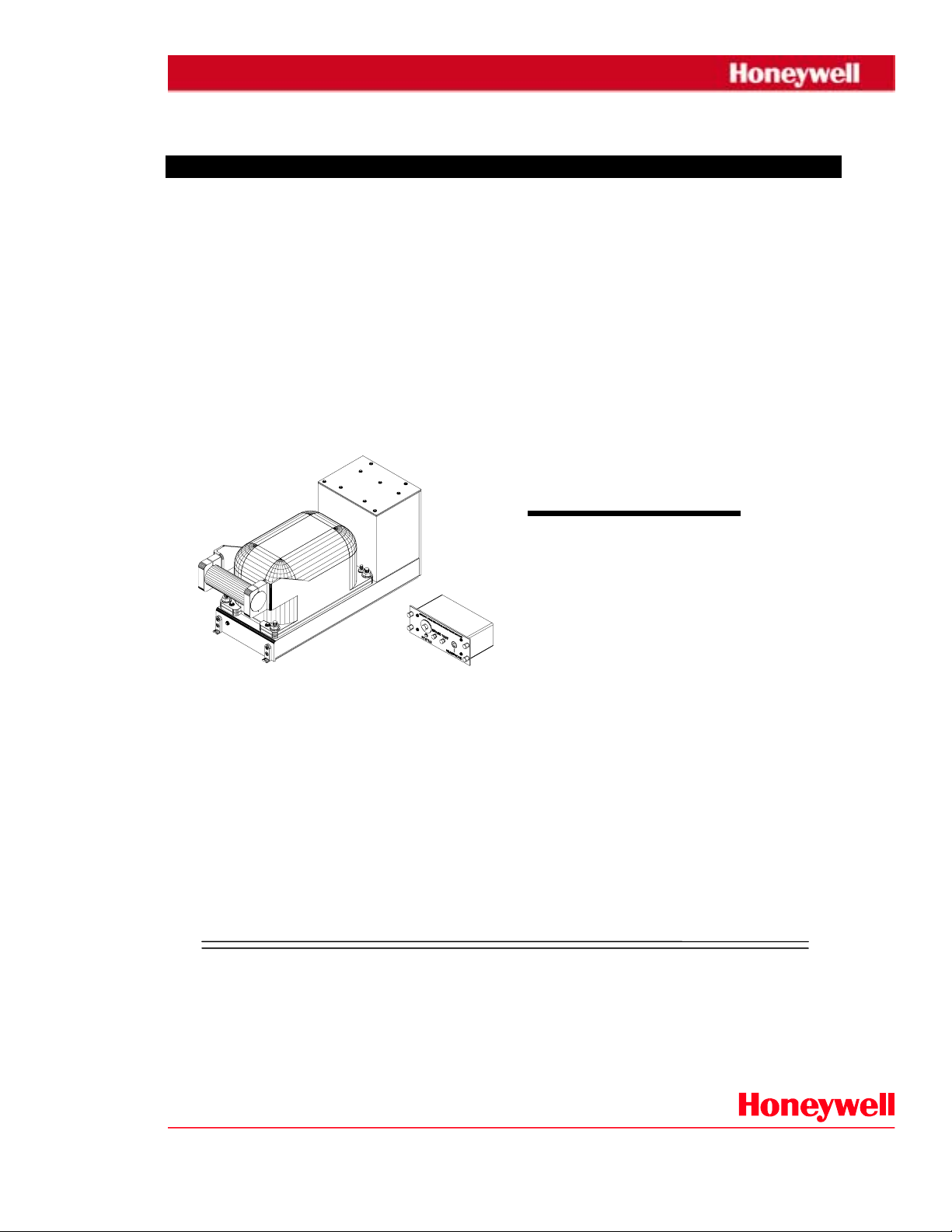
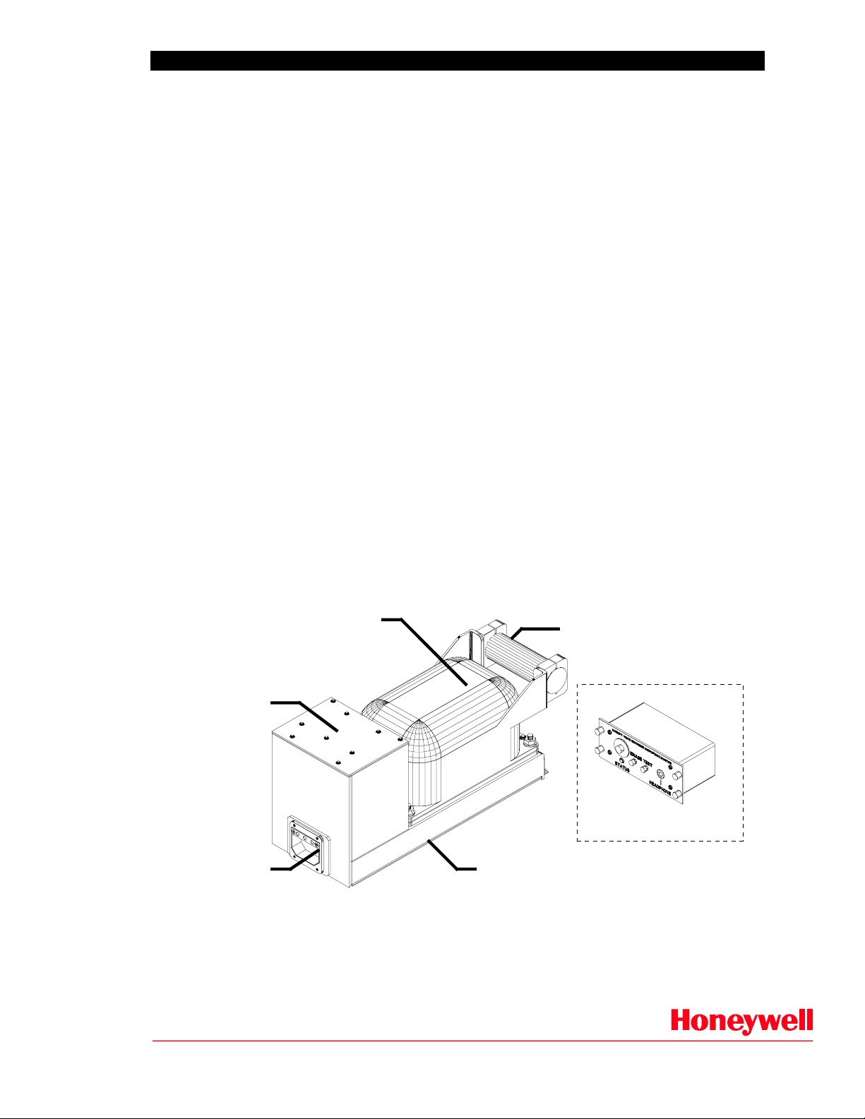
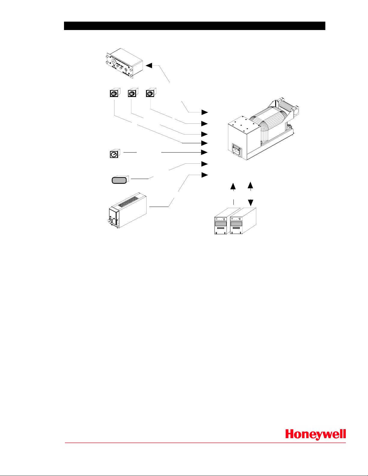
Figure 1 shows the SSCVR and its major features, while Figure 2 provides a simplified diagram showing its
major aircraft interfaces.
ED-56a Crash Survivable
Memory Unit (CSMU)
(30 min. or 2 hr. model)
Under Water
Locator Beacon
(ULB)
115Vac/28Vdc
Power Supply
ED-56a
Microphone Monitor
ARINC-757
Aircraft Interface
Controller Board
ED-56a Audio Processor
Figure 1: Solid-State CVR System, Major Features
CVR_DESC.DOC 3/00
Rev. -B 2
Page 3
SOLID-STATE COCKPIT VOICE RECORDER Description
Microphone
Monitor
Mic. #1 Mic. #2
Rotor
Tachometer
Capt. Clock
14:30:15
Mic. #3
Narrow Band Audio
Rot. Freq.
Flight Data
Acquisition Unit
Test/Erase/Status
Composite Audio
Area Mic. (WB audio)
GMT
FSK Timing
SSCVR
Recorder
BITE
ATC
OMSCMU
Other Subsystem Provisions
Figure 2: Solid-State CVR, Major Aircraft Interfaces
The SSCVR is the most modern available, incorporating the latest interface characteristics defined in
ARINC 757. Audio interface provisions include one (1) wide band and three (3) narrow band channels
meeting the improved signal to noise and bandwidth characteristics specified in ED-56a. In addition to the
audio inputs, the SSCVR also records timing information from either of two sources, GMT from the
captains clock or FSK from the flight data acquisition unit. A dedicated tachometer input is provided for
recording of rotor speed in helicopter applications.
Both the 30 minute and 2 hour SSCVR currently include two ARINC-429 interfaces; one is reserved for
future recording of air traffic control digital message communications, and the second is provided for new
generation aircraft equipped with Onboard Maintenance Systems.
The SSCVR has been designed to achieve a high degree of reliability, as well as facilitating simplified
maintenance and minimal component sparing over competing models.
•••• High Mean Time Between Failure -
in excess of 10,000 hours predicted (per MIL-HDBK-217F) and
in excess of 20,000 hours field operation anticipated.
•••• No Scheduled or Periodic Maintenance is required.
•••• Consists of only (3) three Shop Replaceable Units.
•••• Dual voltage power supply provides fleet wide commonalty.
Extensive micro-processor based built-in-test greatly simplifies test and trouble shooting, thereby
minimizing technician training and support equipment costs.
CVR_DESC.DOC 3/00
Rev. -B 3
Page 4
SOLID-STATE COCKPIT VOICE RECORDER Description
1.0 SSCVR DESIGN OVERVIEW
The SSCVR is a single Line Replaceable Unit (LRU) in a standard ARINC-404A style avionics form
factor. The SSCVR chassis includes three (3) Shop Replaceable Units (SRU's) and an optional underwater
locating device. SRUs include:
a) Interface and Control Board (ICB)
b) 115Vac/28Vdc Dual Voltage Power Supply (PS)
c) Crash Survivable Memory Unit (CSMU)
d) Under Water Locator Beacon (ULB)
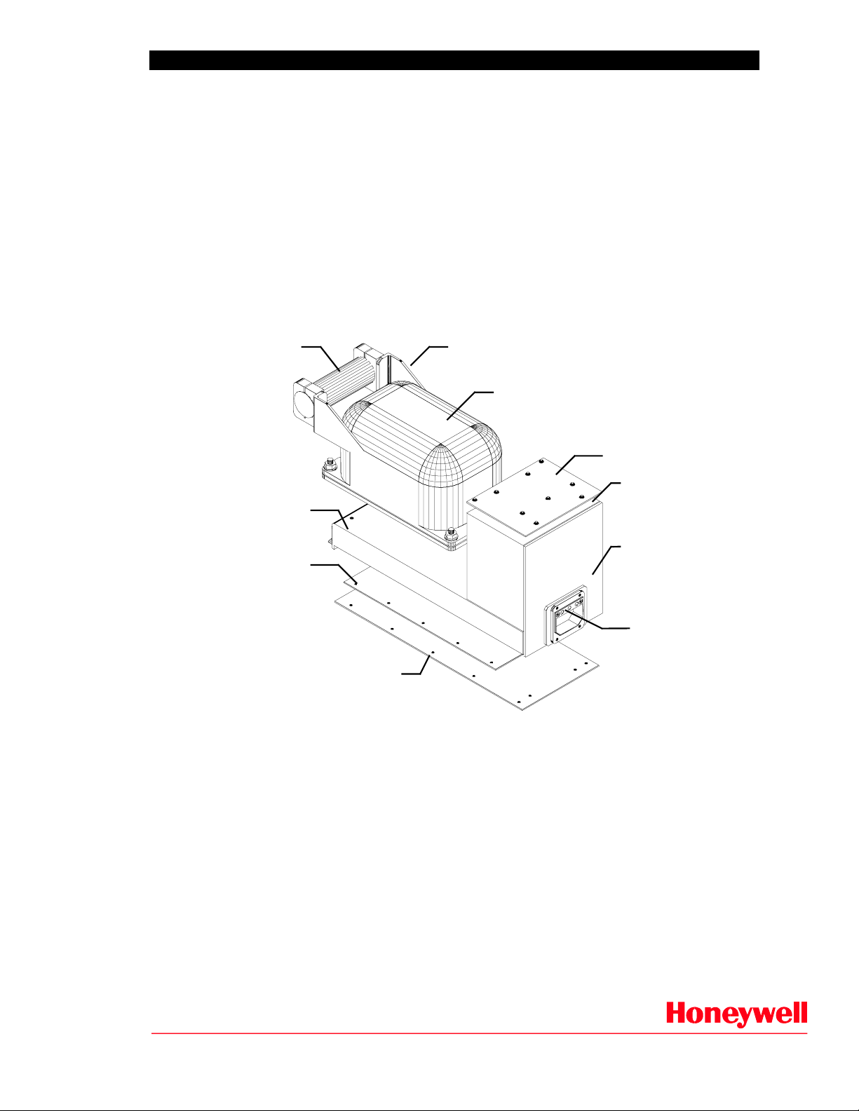
The breakdown of major components and SRU accesses are summarized in Figure 3.
Handle or
Underwater Locator
Beacon (ULB)
CSMU Mounting Shelf
Interface & Control
Circuit Board (ICB)
ICB Access Cover
ULB Mounting
(4 Places)
Crash Survivable
Memory Unit (CSMU)
PS Access Cover
Power Supply (PS)
ARINC-404A
Chassis
ARINC-404A
Connector
Figure 3: SSCVR Exploded View Showing Major SRUs
All three SRUs are readily accessible without requiring major disassembly. The CSMU may be removed
from its mounting shelf by simply removi ng four bolts and releasing its mati ng connector. The plug-in
power supply may be accessed by removing the top (power supply) access panel. Access to the plug-in
interface controller board is accomplished by removing the bottom cover panel from the SSCVR chassis.
An optional under water locator beacon (ULB) approved to TSO C-121 is mounted on the front of the unit
and also serves as a handle. Four (4) mounting bolts firmly attach the ULB directly to the front of the
CSMU to avoid separation in the event of an incident. The mounting of the ULB also facilitates easy access
for replacement of its battery. If the SSCVR is purchased without the ULB, a hollow metal tube is mounted
in its place.
CVR_DESC.DOC 3/00
Rev. -B 4
Page 5

SOLID-STATE COCKPIT VOICE RECORDER Description
2.0 SSCVR OPERATIONAL OVERVIEW
All SSCVR processing and control is performed on a single plug-in circuit board, the Interface and Control
Board (ICB). ICB functions include, front end data conditioning, audio signal digitization and encoding,
control of all states and modes of the system, and performing functions such as record, erase, and test.
Figure 4 provides a simplified block diagram of the ICB.
Narrow Band Audio Processing (150 to 3500 Hz)
Mic. Ch #1
Input
Mic. Ch #2
Input
Mic. Ch #3
Input
Area Mic.
Input
CODEC
AMP
XFMR
AMP
XFMR
XFMR
XFMR
Wide Band Audio Processing (150 to 6000 Hz)
Industry
AMP
Standard
AMP
ADPCM
Audio
CODEC
ADPCM
CODEC
ADPCM
CODEC
ADPCM
PACKER
PACKER
Internal System
Control Bus
CSMU
Buffers
CSMU
Memory
Bus
ARINC-429
Tx Output
ARINC-429
Rx Input
(4 Channels)
FSK Input
Rotor Tach.
Frequency
Input
DRVR
4-Chan.
-429
XCVR
ARINC-429 4-Channel XCVR
DEMOD Det/Format
FSK Detector
RCVR
Rotor Tach F/V Convertor
F/V
Convertor
80C196
MicroController
20 MHz
Embedded Program
32K Bytes
System Controller
-422
XCVR
GBE I/O
RS-422
Figure 4: Interface Controller Board Block Diagram
A key element of the SSCVR design is that the audio recording uses an industry standard encoding method
(G.723 CCITT, 24kbs). This approach provides several advantages to the user:
•••• The audio digitization and encoding are embedded in non-proprietary, commercially
available integrated circuits which have been matured through wide-spread use in consumer
equipment.
•••• The encoding algorithm is extensively used in personal computer based high quality audio
systems, thus decoding/playback tools are inexpensive and readily a vailable from
commercial sources.
The audio circuits, digitization/compression process, and memory resolution meet the improved audio
performance requirements of ED-56a, thereby assuring the highest level of audio recording fidelity. Audio
channel characteristics are summarized as follows:
a) Signal To No Signal 48 dB minimum
b) Cross Talk 40 dB
c) B alance ±3 dB
d) Signal to Noise Plus Distortion 24 dB minimum
e) Speech Transmission Index 0.75(narrow band), 0.85 (wide band)
CVR_DESC.DOC 3/00
Rev. -B 5
Page 6

SOLID-STATE COCKPIT VOICE RECORDER Description
3.0 SSCVR PHYSICAL CHARACTERISTICS
The SSCVR fits the half-ATR-short mounting requirements of ARINC-404A. Recognizing that the SSCVR
will be installed on small-aircraft where space is at a premium, height, which is a non-critical mounting
dimension, has been reduced from the ARINC-404A specification. The SSCVR is sufficiently robust that it
may be hard mounted (i.e. a shock/vibration isolation tray is not required). This, combined with the small
form factor, allows more latitude in mounting location on the aircraft. The physical characteristics of the
unit are:
•••• Mounting: ARINC-404 Half-ATR-Short Tray Mount
•••• Dimensions: 6.1"H x 4.8"W x 12.62"L (plus ULB)
•••• Connector: DPXBMA-57-33S-0001
•••• Weight: Less Than 13 Pounds (11.5 Pounds typical)
•••• Power Dissipation: Less Than 35 Watts (8 Watts typical)
•••• Cooling Method: Convection and Radiation to Ambient Air
Figure 5 illustrates the mechanical interface aspects of the unit.
6.10"
ARINC-404A
Connector
ULB or Handle
1.60" max.
ARINC-404A
Mounting Hooks
(2 places)
12.62" max.
4.80"
Figure 5: SSCVR Mechanical Interface Features
CVR_DESC.DOC 3/00
Rev. -B 6
Page 7

SOLID-STATE COCKPIT VOICE RECORDER Description
4.0 SSCVR ENVIRONMENTAL CHARACTERISTICS
The SSCVR has been fully qualified to meet the environmental service conditions for rack mounted
equipment per DO-160C as outlined below. These conditions have been selected to assure its failure free
use virtually on all commercial transport aircraft which require use of a CVR.
Temperature Per DO-160C Section 4, Category D2
Altitude Per DO-160C Section 4, Category D2
Temperature Variation Per DO-160C Section 5, Category B
Humidity Per DO-160C Section 6, Category B
Mechanical Shock Per DO-160C Section 7
Vibration Per DO-160C Section 8
Explosion Proofness Per DO-160C Section 9, Category E1
Waterproofness Per DO-160C Section 10, Category X
Fluid Susceptibility Per DO-160C Section 11, Category X
Sand and Dust Per DO-160C Section 12, Category X
Fungus Resistance Per DO-160C Section 13, Category F
Salt Spray Per DO-160C Section 14, Category X
Magnetic Effect Per DO-160C Section 15, Category A
Operational Limits: Continuous -55°C to +70°C
Non-operational Limits: Continuous -55°C to +85°C
Altitude: Sea Level to +50,000 feet
Operating Shock: Up to 6G over 11 msec half-sine
Crash Safety: Up to 15G over 11 msec half-sine
Fixed Wing Aircraft: Per Test Curve B, C, L, M
Helicopter Vibration: Per Test Curve N, V
Magnetic Deflection: 0.3-1.0m Distance allowed
Power Input Per DO-160C Section 16, Category A
Voltage Spikes Per DO-160C Section 17, Category A
Audio Frequency Conducted Susceptibility Per DO-160C Section 18, Category A
Induced Signal Susceptibility Per DO-160C Section 19, Category Z
Radio Frequency Susceptibility Per DO-160C Section 20, Category V
Emission of Radio Frequency Energy Per DO-160C Section 21, Category Z
Lighting Induced Transient Susceptibility Per DO-160C Section 22, Category L
Lighting Direct Effects Does not apply.
Icing Per DO-160C Section 23, Category X
CVR_DESC.DOC 3/00
Rev. -B 7
Input Power: AC or DC Power
Power Interruptions: 200 msec. without upset.
Page 8

SOLID-STATE COCKPIT VOICE RECORDER Description
r
5.0 SSCVR CRASH PROTECTION DESIGN
The SSCVR's crash survivable memory unit (CSMU) provides for complete data recovery when subjected
to the crash conditions stipulated in ED-56a, and thereby the intent of TSO C-123A :
•••• Impact Shock 3400G, 6.5 milliseconds
•••• Penetration Resistance 500 lb. weight from 10 feet
•••• Static Crush 5000 lbs., 5 minutes
•••• High Temperature Fire 1100°°°°C, 30 minutes
•••• Low Temperature Fire 260°°°°C, 10 hours
•••• Deep Sea Pressure and 20,000 feet, 30 days
•••• Sea Water/Fluids Immersion Per ED-56a
The CSMU design has been fully qualified to these requirements and, in fact, exceeds them by
considerable margin in key survival areas:
•••• Impact shock has been successfully demonstrated at 4800 G's
•••• High temperature fire exposure has been tested to 60 minutes
•••• Low temperature fire was tested immediately after exposure to 1100°°°°C fire
The superior performance of the CSMU is the result of 30 years experience with designing and producing
protective enclosures. As shown in Figure 6, a very simple package design has been achieved, which not
only contributes to its industry leading survivability characteristics, but also assures a high degree of
maintainability. Compared to competing models, requirements for specialized repair knowledge and
support equipment have been greatly reduced.
Housing
Steel Armor
Thermal Block
Upper Module
Memory Board
FLASH Memory ICs
Access Cover
Steel Armor
Insulation
Housing Liner
Patent
Protected
Insulation
Cover Line
Thermal Block
Lower Module
Figure 6: CSMU Cutaway View Showing Major Features
The CSMU is easily removed from the top of the SSCVR chassis without having to disassemble the
remainder of the unit. A steel bottom cover provides easy access to the Memory Board. Since the CSMU
uses modular "dry-block" materials for both the insulating liner and thermal mass, there is no need to deal
with the sticky thermal jells or special insulating fluids. The Memory Board design is very simple,
consisting of only a single small circuit card assembly.
CVR_DESC.DOC 3/00
Rev. -B 8
Page 9

SOLID-STATE COCKPIT VOICE RECORDER Description
6.0 MICROPHONE MONITOR DESIGN OVERVIEW
The SSCVR provides for interface with a standard microphone monitor, or alternatively a remote area
microphone and pre-amplifier as described in paragraph 6.1. The microphone monitor is a small instrument
panel mounted device intended for location in the cockpit ambient audio environment. It includes a built-in
area microphone for transducing the cockpit area audio spectrum (crew conversation and ambient sounds
such as engines, actuators or control switch toggles) for recording on the SSCVR's area microphone
channel. In addition to the reception and conditioning of the cockpit audio, the microphone monitor also
provides several cockpit voice recorder related status indicators and controls. These are described as
follows:
• HEADPHONE A standard headset jack which enables maintenance crew members to verify that
audio signals are being properly detected by the SSCVR's audio recorder
function.
• ERASE Push button switch which enables the crew member to erase the audio portion of
the SSCVR's audio recording memory.
• TEST Push button which enables the SSCVR to be commanded into a self test mode.
• STATUS Provides an indication of the correct operational status for the SSCVR's audio
recording func tions in response t o a Push-to-Test.
The microphone monitor shown, in Figure 7, includes a wideband preamplifier with automatic gain control
for conditioning the area microphone audio signal prior to output to the recorder. This design meets the
signal-to-noise and signal sensitivity requirements of ED-56a, thus providing the optimum in audio quality
to the recorder. The Microphone Monitor is approved to TSO C-123.
DZUS Fastener
(4 places)
2.25" max.
5.75" max.
Aircraft Interface Connector
Bendix PT02A20-41P
2.6" max.
Weight = 1.0 lbs max.
Figure 7: Microphone Monitor Mechanical Interface Features
•••• Input Power: +18 Vdc ±±±± 3.6 Vdc
(supplied by SSCVR)
•••• Audio Characteristics: Frequency Response 150 Hz to 10,000 Hz
Signal to Noise Ratio 48dB, 95 - 120dB SPL
Harmonic Distortion < 3% at 120 dB SPL
Output Range AGC limited, 0.5 Vrms
• Weight 1.0 pounds maximum
CVR_DESC.DOC 3/00
Rev. -B 9
Page 10

SOLID-STATE COCKPIT VOICE RECORDER Description
6.1 REMOTE AREA MICROPHONE AND PRE-AMPLIFIER DESIGN OVERVIEW
The SSCVR can also interface with a standard area microphone, without the need for the monitor unit. The
area microphone is a small device intended for location in the cockpit ambient audio environment. It is
available in several configurat ions : as a flange mounted devises, as shown in Figure 8, or without the flange
and with flying leads, as shown in Figure 9.
The remote area microphone provides an input to the pre-amplifier shown in Figure 10, which includes a
wideband preamplifier with automatic gain control for conditioning the area microphone audio signal prior
to output to the recorder. This design meets the signal-to-noise and signal sensitivity requirements of ED56a, thus providing the optimum in audio quality to the recorder. The remote area microphones and preamplifier are approved to TSO C-123.
Figure 8: Area Microphone Interface Features
Figure 9: Area Microphone - alternative
•••• Input Power: +5 Vdc ±±±± 1 Vdc
•••• Current: 300µµµµA max imum
•••• Audio Characteristics: Frequency Response 150 Hz to 10,000 Hz
Signal to Noise Ratio 48dB, 95 - 120dB SPL
Harmonic Distortion < 5% at 90dB SPL
over 150 to 8,000 Hz
<10% at 120dB SPL
at 10,000 Hz
• Weight 3.5 ounces maximum
CVR_DESC.DOC 3/00
Rev. -B 10
Page 11

SOLID-STATE COCKPIT VOICE RECORDER Description
Figure 10: Pre-amplifier Interface Features
•••• Input Power: +18 Vdc ±±±± 3 Vdc
•••• Current 100 mA maximum
•••• Audio Characteristics: Frequency Response 150 Hz to 10,000 Hz
Signal to Noise Ratio 48dB, 95 - 120dB SPL
Harmonic Distortion < 3% at 120 dB SPL
Output Range AGC limited, 0.5 Vrms
Bandwidth 150 - 10,000 Hz
• Weight 0.7 pounds maximum
CVR_DESC.DOC 3/00
Rev. -B 11
Page 12

SOLID-STATE COCKPIT VOICE RECORDER Description
7.0 SSCVR SYSTEM SUPPORT EQUIPMENT
The Playback and Test Station (PATS) is a cost effective shop level personal computer (PC) based system
with associated software which performs download of SSCVR recording memory, decompression and
playback of the downloaded data, and acceptance test of the SSCVR. Because the "TEST" function does
not preserve the data contained in the recording memory, the PATS operations are segmented into two
distinct applications; "Playback" and "TEST". This provides a level of protection against unintentional
erasure or re-write of recorded audio. Figure 11 shows the PATS in its SSCVR test configuration.
Playback Program
Audio Board #1, #2, #3
(4-Ch. Digital Audio I/O)
GBE I/B
RS-422
ARINC-429
Download
Application S/W
GBE I/B
RS-422
Data/Audio
Storage
Playback and Test
Station
Playback
Application S/W
Audio #1
Audio #2
P/B Board
Audio #1
P/B Board
GBE I/B
429/422
"TEST"
Application S/W
Data/Audio
Storage
TEST Program
SSCVR
Test Cable
SSCVR
Figure 11: SSCVR Playback and Test System Configuration
The PATS is configured with a GBE Interface Board containing the high speed RS-422, discrete
interfaces, and ARINC-429 interface channels necessary to test the SSCVR functions. The PATS also
contains up to 3 commercial dual-channel digital-audio boards. These are used for audio input/output
during CVR audio tests, and for audio output (to speakers) during playback. A 486-33MHz PC
provides the necessary minimum computing capability to support all SSCVR TEST and PLAYBACK
tasks for both the 30 minute and 2 hour SSCVRs.
CVR_DESC.DOC 3/00
Rev. -B 12
Page 13

SOLID-STATE COCKPIT VOICE RECORDER Description
The PATS test and playback programs are implemented using MS Windows as the user interface. This
approach provides very easily understood menu driven test operations which require minimal operator
training. Figure 12 shows the main menu window from the SSCVR "TEST" program.
Figure 12: SSCVR Test Program, Example of Main Window
Figure 13 shows the control screen during "PLAYBACK" operation. This example screen of an SSCVR
recording shows the approximate recorded duration of the playback audio, as well as a summary list of
TIME messages, Rotor Speed and provision for ATC COMMunications Data (CMU) messages. The
operator may move the cursor to select a particular point in the audio recording. All message windows
retain a time stamp to assist in cross correlation of events.
Figure 13: SSCVR Playback Program, Example of Main Window
CVR_DESC.DOC 3/00
Rev. -B 13
 Loading...