

Page 1

Put Bar Code Here
Technical Reference Manual
Design and Application Guide for
Honeywell Economizer Controls
63-8594-02
Page 2

Page 3

Table of Contents
Section 1 - Ventilation ...................................................................................1
Indoor Air Quality ...............................................................................................................................................................2
Building-Related Illness .....................................................................................................................................................3
Symptoms of Inadequate Ventilation .................................................................................................................................4
Indoor Air Ventilation Standards .........................................................................................................................................5
Based Demand Control Ventilation .................................................................................................................5
CO
2
Energy Standards ..............................................................................................................................................................6
Ventilation Requirements .................................................................................................................................................7
Air Handler Control Loops ..................................................................................................................................................9
Basic Economizer Control ................................................................................................................................................10
Mixed Air Formulas ..........................................................................................................................................................11
Outside Air Percentage Chart ..........................................................................................................................................12
Example 1: Using the Outside Air Percentage Chart ............................................................................................13
Example 2: Use of Outside Air Chart on a Warm Day ..........................................................................................14
Extra Outside Air Percentage Chart ......................................................................................................................15
Example 3: Minimum Ventilation Adjustment ........................................................................................................16
Example 4: Ventilation Review Questions .............................................................................................................18
Economizer Cycle Definition ............................................................................................................................................20
Single and Two Stage Cooling With Economizer ..................................................................................................21
Section 2 - Enthalpy Theory And Controllers ...........................................23
The Psychrometric Chart .................................................................................................................................................24
Relative Humidity and Saturation .....................................................................................................................................25
Enthalpy ...........................................................................................................................................................................26
Psychrometric Chart of Enthalpy Economizer Control ..........................................................................................27
Single Sensor Enthalpy Control .......................................................................................................................................28
Two Sensor or Differential Enthalpy .................................................................................................................................29
Enthalpy Control with Carbon Dioxide Sensor ................................................................................................................. 30
Section 3 - Types of Analog Economizers ................................................31
H705 ................................................................................................................................................................................32
W7459 .............................................................................................................................................................................33
W6210 and W7210 ..........................................................................................................................................................34
W6215, W7215 and W7460 .............................................................................................................................................35
W7212, W7213 and W7214 .............................................................................................................................................36
W7340 and W7345 ..........................................................................................................................................................37
Analog Economizer Features ...........................................................................................................................................38
Transformer Wiring Requirements for Analog Economizers ............................................................................................39
Section 4 - H705 Economizer Module ........................................................41
H705 Economizer Module ................................................................................................................................................42
H705 Components ...........................................................................................................................................................43
H705 Enthalpy Setpoint ...................................................................................................................................................44
H705 Wiring Diagram .......................................................................................................................................................45
Section 5 - M7XXX Black Motor ..................................................................49
M7215, M7415, M7405 and M8405 Actuators .................................................................................................................50
Honeywell Economizers 63-8594-02 i
Page 4

Section 6 - W7459 Economizer Module .....................................................53
W7459 Enthalpy Module Components .............................................................................................................................54
W7459A, B, C and D ........................................................................................................................................................56
W7459 Enthalpy Setpoint Chart .......................................................................................................................................57
High Limit Switching .........................................................................................................................................................58
W7459A Wiring Diagram .................................................................................................................................................59
Section 7 - W6210 And W7210 Economizer Modules ...............................63
W7210 Economizer System Components .......................................................................................................................64
W6210 and W7210 Components .....................................................................................................................................65
High Limit Function ................................................................................................................................................65
W7210 Actuator Connections .........................................................................................................................................66
W7210 Wiring Diagrams ..................................................................................................................................................67
Section 8- W6215, W7215 And W7460 Economizer Modules ...................69
W7215 System Components ...........................................................................................................................................70
W6215, W7215 and W7460 Components ........................................................................................................................71
W7215B and W7460B Components ................................................................................................................................71
W6215, W7215, W7460 Inputs and Outputs ....................................................................................................................72
Input and Output Applications ..........................................................................................................................................72
Minimum and Maximum Settings .....................................................................................................................................73
Indoor Air Content Sensor Settings .................................................................................................................................74
Carbon Dioxide Sensor Setup .........................................................................................................................................75
Outdoor Air Content Sensor .............................................................................................................................................76
W6215, W7215 and W7460 Actuator Usage ...................................................................................................................77
W6215, W7215 and W7460 Wiring Diagram ..................................................................................................................78
Section 9 - W7212, W7213 and W7214 Economizer Modules ..................81
W7212 Economizer System Components .......................................................................................................................82
W7212, W7213, and W7214 Components .......................................................................................................................83
DCV Maximum Position Adjustment ......................................................................................................................84
Using Multiple CO2 sensors on the AQ-AQ1 terminals for zones .........................................................................85
Minimum Position Adjustment ...............................................................................................................................85
Dry bulb changeover .............................................................................................................................................86
W7212, W7213, and W7214 Wiring Diagram ..................................................................................................................87
Section 10 - W7340 and W7345 Economizer Module ................................93
W7340 Economizer System Components .......................................................................................................................94
W7340 and W7345 Components .....................................................................................................................................96
W7340 only ...........................................................................................................................................................97
Demand Control Ventilation (DCV) Sensor Input (W7340 only) ............................................................................97
Settings and Adjustment .......................................................................................................................................99
Wiring for W7340 and W7345 ........................................................................................................................................101
Section 11 - W7220 JADE™ Economizer Module ...................................103
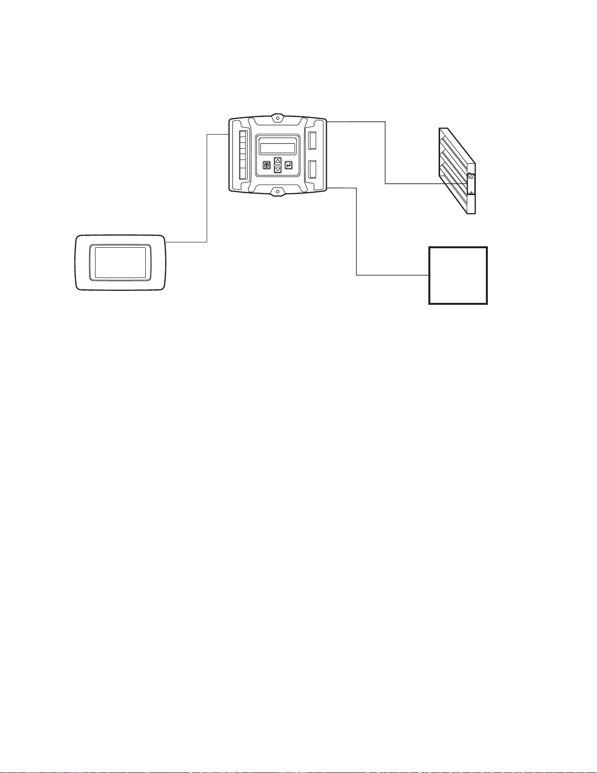
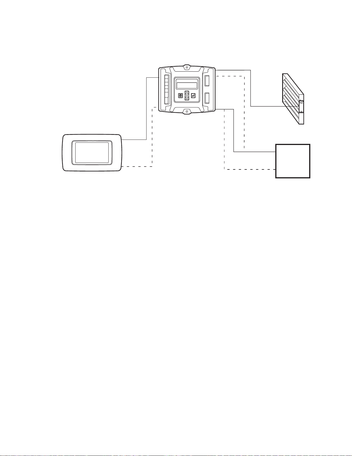
W7220 Economizer System Components .....................................................................................................................104
W7220 Components ......................................................................................................................................................106
Wiring Application Examples .........................................................................................................................................109
W7220 (JADE™) Economizer Controller Used with Honeywell Prestige
Alarm Mode for Failed Components on the JADE™ economizer system ...........................................................129
W7220 Personal Computer Tool ....................................................................................................................................134
©
IAQ 2.0 Thermostat ....................................129
Section 12 - Sensors for Economizer Modules .......................................157
Sensor Features ............................................................................................................................................................158
Type of Sensors for Economizer ....................................................................................................................................159
C7150 and C7046 Mixed and Supply Air Sensors .........................................................................................................162
ii Honeywell Economizers 63-8594-02
Page 5

Mixed or Supply Air Sensor Control Sequence ..............................................................................................................163
Carbon Dioxide Sensor ..................................................................................................................................................163
TM
JADE
Economizer (W7220) Sensors .........................................................................................................................164
Section 13 - Checkout ...............................................................................167
Standard Checkout Procedure .......................................................................................................................................168
Checkout W7212 ...........................................................................................................................................................168
Check out C7400 with W7459, W7210 and W7212 .......................................................................................................170
Check out for W7220 JADE
TM
Economizer ...................................................................................................................172
Section 14 - Simulator for W7212 .............................................................173
Section 15 - Demo for W7220 ...................................................................177
Section 16 – Economizer Savings Estimator .........................................181
Section 17 - Retrofit and Upgrades ..........................................................183
Replacement of W7459Axxx and M7415Axxx with W7220A1000 (JADETM) and M7215A1008 ................................188
Replacement of W7212Axxx with W7220A1000 (JADE
Replacement of W7210Axxx with W7220A1000 (JADE
Replacement of W859F with W7220A1000 (JADE
Replacement of W957G with W7220A1000 (JADE
W957G Replaced with W7220 and M7285A1045 Mod Motor .............................................................................198
Cross Reference ............................................................................................................................................................199
W7220 JADE
TM
Y-Pack Table .......................................................................................................................................203
TM
) ..........................................................................................191
TM
TM
) ..........................................................................................193
) and M7285A1045 .....................................................................195
TM
) and M7285A1045 ....................................................................197
Section 18 - Appendix ...............................................................................207
Glossary .........................................................................................................................................................................207
Accessories for the M74XX Series Actuators ................................................................................................................210
Accessories for the W7220 JADE
TM
Economizer Module .............................................................................................211
Honeywell Economizers 63-8594-02 iii
Page 6

iv Honeywell Economizers 63-8594-02
Page 7
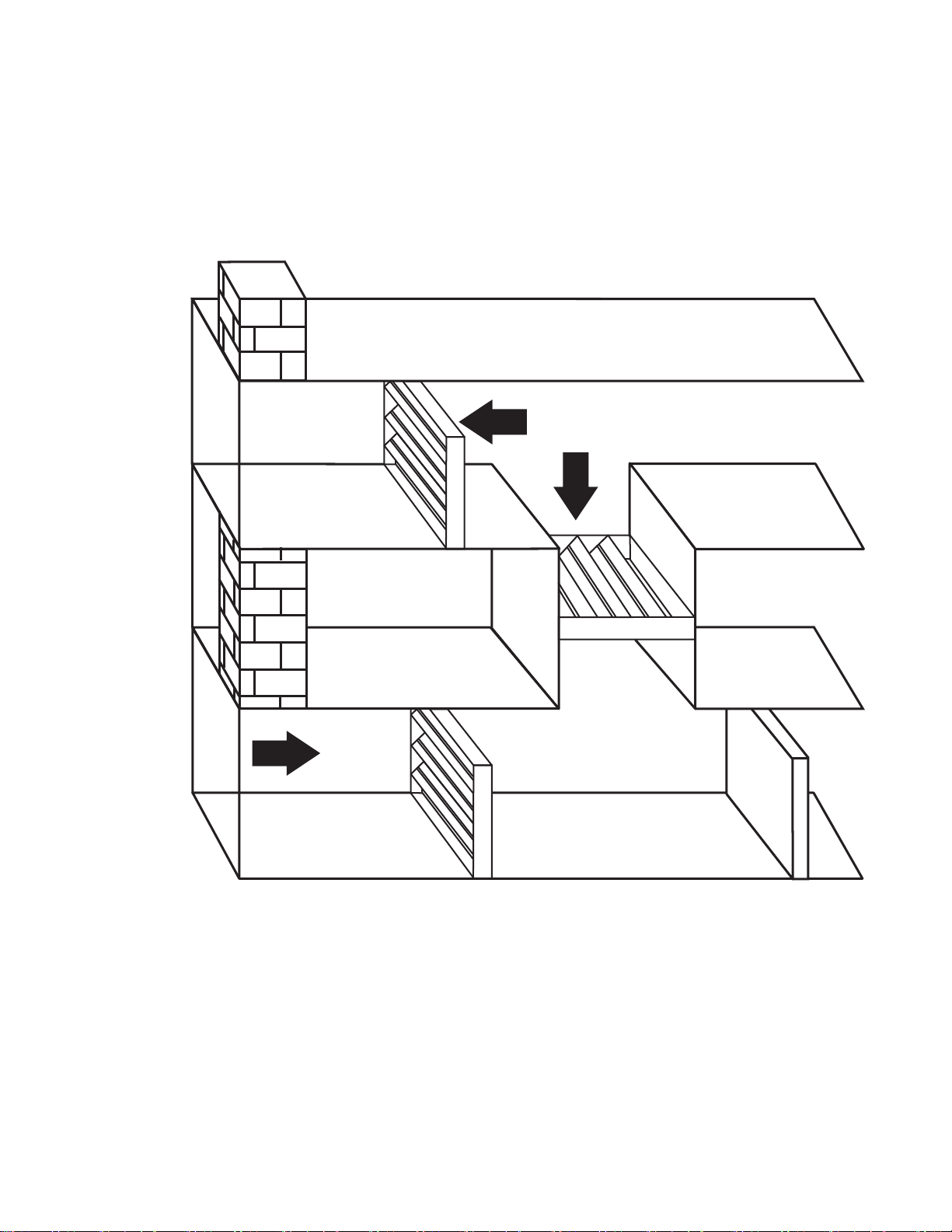
Section 1 - Ventilation
M23621
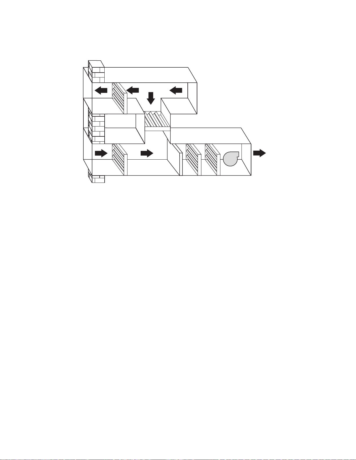
MIXED AIR SECTION
O.A.
FILTERS
EX.
AIR
DAMPER
DAMPER
DAMPER
Section 1 - Ventilation
1 Honeywell Economizers 63-8594-02
Page 8

Section 1 - Ventilation
Indoor Air Quality
The characteristics of the indoor climate of a building, including the gaseous
composition, temperature, relative humidity, and airborne contaminants.
The Arab oil embargo of 1974 caused many
building designers to begin implementing
energy cost reduction measures. One of these
measures was to seal up the building shell to
reducing exfiltration of indoor air and the
resultant heat loss. Energy costs were
reduced but there was a significant negative
side effect that was not detected until 1988:
Indoor Air Quality. Many buildings constructed
prior to 1974 had sufficient leakage through
poorly sealed windows and doors to
adequately ventilate the building. Construction
methods used between 1974 and 1988
substantially reduced this leakage. As a result
many buildings constructed between 1974 and
1988 are not adequately ventilated for the
occupants.
As the energy costs continue to rise into the
beginning of the 21st century, building
managers are seeking ways to reduce the
energy usage in new and existing buildings
and continue to provide a healthy environment
for the building occupants.
Honeywell Economizers 63-8594-02 2
Page 9

Section 1 - Ventilation
Healthy Air
Building-Related Illness
A diagnosable illness with identifiable symptoms whose cause can be
directly attributed to airborne pollutants within a building such as
Legionnaires disease or hypersensitivity pnuemonitis.
The American Society of Heating,
Refrigeration, and Air Conditioning Engineers
(ASHRAE) are engineers in the HVAC
industry who establish standards for the
mechanical equipment used to heat, cool and
ventilate buildings. Many local, state, national
and international buildings codes are based
on these standards. ASHRAE Standard
62.1,Ventilation for Acceptable Indoor Air
Quality, is the ventilation standard for
commercial buildings. It states “indoor air
quality is acceptable when there are no known
contaminants at concentrations determined to
be harmful to building occupants, as
determined by cognizant authorities, and
when a substantial majority (80% or more) of
those persons exposed to the indoor air do not
express dissatisfaction with its quality.” This
standard sets minimum outdoor air ventilation
rates and requires other measures intended to
provide indoor air quality that is both
acceptable to human occupants and
minimizes negative effects on health.
3 Honeywell Economizers 63-8594-02
Page 10

Section 1 - Ventilation
Headaches
Dizziness
Symptoms of Inadequate Ventilation
Drowsiness
Fatigue
Nausea
Eye Irritation
Causes of poor indoor air quality are not
always caused by the design of the building.
Poor or improper maintenance such as
outdoor air dampers that are blocked open or
completely closed, defective damper actuators
or incorrectly set or malfunctioning controls
may also cause inadequate ventilation. Many
maintenance people respond to occupant
complaints with only temperature in mind. If
the room is within the acceptable temperature
Respiratory Irritation
range of 68 to 78°F. (20 to 26°C) it is
perceived that no adjustments are necessary.
The occupants may have many of the
symptoms listed above but do not have the
knowledge to request “open the outside air
damper” or “increase the volume of supply air
to this room.” It is incumbent on the
knowledgeable HVAC service person to
recognize inadequate ventilation when it is
encountered.
Honeywell Economizers 63-8594-02 4
Page 11

Indoor Air Ventilation Standards
Section 1 - Ventilation
ASHRAE is continually updating the
ventilation standard (ASHRAE 62.1) to provide
guidelines for design and maintenance of
buildings. These standards are recommended
guidelines only and are not legal
requirements. However many state and local
codes use the ASHRAE standards as the
basis for building codes for new construction
and building occupancy. They also form a
basis for litigation in indoor air quality lawsuits.
Some measurements and gases referred to in
the standards may not be familiar to the
average person in the HVAC industry.
However the majority of the information
contained in these standards is very clearly
stated. Everyone in the HVAC industry should
be knowledgeable about the contents of these
standards.
The ventilation standard states a minimum
outdoor air ventilation rate required per person
per type of environment in Cubic Feet per
Minute (cfm). The ventilation requirement
varies between occupied and unoccupied
periods. Outdoor air dampers are set to a
minimum position based on the maximum
occupancy level for the space. To save energy
the ASHRAE 62.1 standard also allows
ventilation to be based on a CO
sensor input
2
that determines occupancy. This is commonly
referred to as CO
-based demand control
2
ventilation (DCV).
CO2 Based Demand Control
Ventilation
CO2 is a fairly dependable indicator of the
concentration of the odorous bioeffluents
exhaled by human beings. Therefore we can
use CO2 concentration levels in a space to
determine the human occupancy and reduce
outdoor air intake when the space is not
occupied to the maximum design occupancy
level. CO
-based DCV is an energy
2
conservation measure; its purpose is to
reduce outdoor air intake rates and the energy
required to condition the outdoor air when
spaces are not occupied at maximum design
densities.
For those who do not want to read an
engineering standard, ASHRAE offers a user
manual that:
• offers information on the intent and
application of Standard 62.1
• provides sample calculations and examples.
• provides useful reference materials.
• gives guidance to building operation and
maintenance personnel.
Standard 62.1 Ventilation
for Acceptable Indoor Air Quality
(ANSI Approved)
The Standard and User's Manual can be
ordered from:
ASHRAE Publications Sales
1791 Tullie Circle, N.E.
Atlanta, GA 30329 or
www.ashrae.org
5 Honeywell Economizers 63-8594-02
Page 12

Section 1 - Ventilation
Energy Standards
There are four ASHRAE standards that affect
energy use in buildings: Standard 90.1,
Standard 90.2, Standard 100 and Standard
189.
Standard 90.1
Energy Efficient Design of New
Buildings covers all buildings except low-rise
residential for new design and build. It has
been used for all buildings in the past due to
the lack of detail in Standard 100.
Standard 90.2 Energy Efficient Desin of New
Low-Rise Buildings covers low-rise residential
buildings and has lacked detail in the past.
Standard 100 Energy Efficiency in Existing
Buildings is the energy standard for existing
buildings including residential. It was revised
in 2012 to include compliance requirements,
energy use analysis methods and energy
targets, operation and maintenance and
energy audit requirements for existing
buildings for energy efficiency. There is also
an extensive list of Energy Efficiency
Measures that can be incorporated into
existing buildings for energy efficiency.
Standard 189
Design of High-Performance
Green Buildings except Low-Rise Residential
Buildings – developed in conjunction with the
US Green Buildings Council that goes beyond
the requirements of Standard 90.1 for “green”
buildings.
The standards are used as the basis for many
federal, state and local jurisdictions as the
energy code. If a state does not use the
ASHRAE standards for the basis of the codes,
they will use the International Energy Code
Council (IECC) code.
In addition to the standards, ASHRAE has
developed a series of publications designed to
provide recommendations for achieving
energy savings over the minimum code
requirements of Standard 90.1 The guides
were developed in collaboration with The
American Institute of Architects (AIA), the
Illuminating Engineering Society of North
America (IES), the US Green Building Council
(USGBC) and the U.S. Dept of Energy (DOE).
All guides are free for download at the
ASHRAE website.
Honeywell Economizers 63-8594-02 6
Page 13
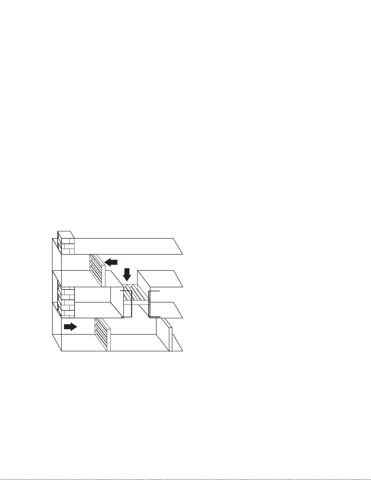
Ventilation Requirements
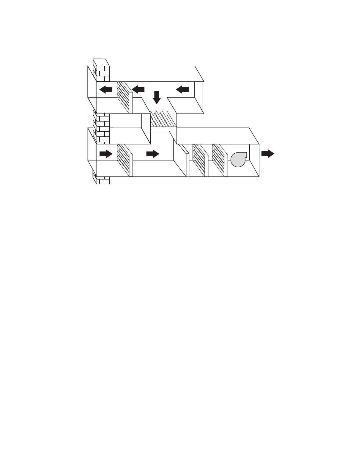
M23621A
MIXED AIR SECTION
O.A.
FILTERS
EX.
AIR
DAMPER
DAMPER
DAMPER
Section 1 - Ventilation
Ventilation is defined as the process of
bringing outside air into a building. The four
major reasons for ventilation are:
1. To ensure a healthy atmosphere for the
occupants. Ventilation is used to dilute
indoor contaminants and provide fresh air
for breathing.
2. To pressurize the building. Positive
pressure inside a building prevents
infiltration of unconditioned and unfiltered
outside air through openings.
3. To provide atmospheric cooling. Bringing
in cool outside air is more energy efficient
and less costly than using mechanical
cooling equipment.
4. To replace air that is being exhausted.
The term for this is make-up air.
Whenever air is exhausted, replacement
air must be provided.
ventilation system. Section 6 of ASHRAE 62.1
offers two procedures designers can use to
determine ventilation rates, the Ventilation
Rate Procedure (VRP) and the Indoor Air
Quality Procedure (IAQP).
The VRP method is based on typical spaces
and usage, the rates are intended to dilute and
exhaust bioeffluents from occupants and
building contaminants to satisfy the 80% of the
occupants of the space. There are two
sources of contaminants in a space that
ventilation is intended to reduce: Occupants
and their activities (e.g., use of office
equipment) and Off-gassing from building
materials. The ventilation rate in the breathing
zone (Vbz) required for both people related
sources (Vp) and building related sources (Va)
is:
Vbz = Vp + V
a
Vp and Va both have two components; Vp is
the number of people in the space (Pz) times
the occupant comfort factor Rp (minimum
ventilation rate determined by extensive
studies for occupant comfort based on activity
level in the space) and Va is the area of the
space (Az) times the building component
factor Ra (minimum ventilation rate
determined by extensive studies for occupant
comfort based on type of space). Therefore
ventilation required in the breathing zone
becomes:
The air controls in the mixing section of a
HVAC unit are used to maintain a minimum
ventilation volume at all times. This is in
addition to controlling the dampers for
atmospheric cooling.
Determining the amount of ventilation required
for a space is probably one of the hardest
tasks an engineer faces in the design of the
Vbz = RpPz + RaA
z
Rp and Ra values are found in ASHRAE 62.1
User’s manual (Table 6-A) and ASHRAE 62.1
Standard.
The outdoor air or recirculated air may be
cleaned using a filter or air cleaner but the
outdoor air ventilation rates cannot be reduced
below the rate determined by the above
formula.
7 Honeywell Economizers 63-8594-02
Page 14

Section 1 - Ventilation
The IAQP method is used for spaces where
the designers target a specific contaminant
and control the concentration level of the
contaminant. This method has two
requirements: Maintain concentration of
specific contaminant(s) below target
concentration limits and achieve a design
target of perceived indoor air quality
acceptability. The IAQP method allows
ventilation rates to be lower than the rates
required by the VRP method if it can be
demonstrated the resulting air quality can
meet the required criteria.
The IAQP procedure has 4 steps:
• Identify the contaminants of concern.
• Determine acceptable concentration of
contaminant(s).
• Specify the perceived indoor air quality
criteria.
• Apply an acceptable design approach to
achieve the performance criteria.
Additional information on ventilation and the
two methods used to determine the ventilation
rates can be found in ANSI/ASHRAE Standard
62.1 and in the User’s manual for ANSI/
ASHRAE Standard 62.1. Both documents are
available on the ASHRAE website at
http://resourcecenter.ashrae.org/store/ashrae/
Example using the VRP method: Office space
of 6600 sq. feet with maximum occupancy of 7
persons per 1000 ft2.
Vbz = RpPz + RaAz where
Rp = 5 cfm per person
(Table 6-A ASHRAE 62.1 User’s Manual)
Pz = 7 person per 1000 ft2 x A
z
Ra = 0.06 cfm per ft2
(Table 6-A ASHRAE 62.1 User’s Manual)
Az = 6600 ft2.
Vbz = 5 ft3 / min/person x 7 persons/1000 ft2 x
6600 ft2 + 0.06 ft3/ min/ft2 x 6600 ft
2
= 231 cfm + 396 cfm
=627 cfm
For a single zone system V
ventilation) is the same as V
(outdoor
OT
. For multiple
bz
zone systems a zone air distribution system
effectiveness (E) factor needs to be used in
the calculation of the V
. See ASHRAE
OT
Standard 62.1 for method.
In our example during maximum occupancy
the ventilation is 627 cfm. When the
occupancy rate is less than the maximum
occupancy, the ventilation rate can be
adjusted to a lower occupancy and the
ventilation increased as the CO
level in the
2
space increases. This can be done following
these steps:
• Calculate the VOT.
• Use Vbz = RpPz + RaAz, where Pz = 0. This
is the new ventilation rate Vat (the area
building based component).
• Add a CO2 sensor to the space.
• Adjust the CO2 maximum to the Vbz (for
maximum occupancy).
• Adjust the minimum position for occupancy
for Va.
In our example the Vbz ventilation is 627 cfm
and the minimum position (Va) is 396 cfm.
Using a CO2 sensor for Demand Control
Ventilation, the new minimum position is set
for 396 cfm and the maximum damper position
for occupancy ventilation is 627 cfm. When
one person enters the space or the
commercial thermostat goes into occupancy
mode, the outdoor air dampers will open to
bring in 396 cfm of outdoor air. As space
occupancy increases, the CO2 level will
increase and the outdoor air dampers will
modulate open to the maximum of 627 cfm of
outdoor air.
NOTE: When the commercial thermostat calls
for free cooling using an economizer,
the dampers are still allowed to
override the DCV maximum position
for ventilation and open the damper
100% open for maximum free cooling.
Honeywell Economizers 63-8594-02 8
Page 15
Section 1 - Ventilation
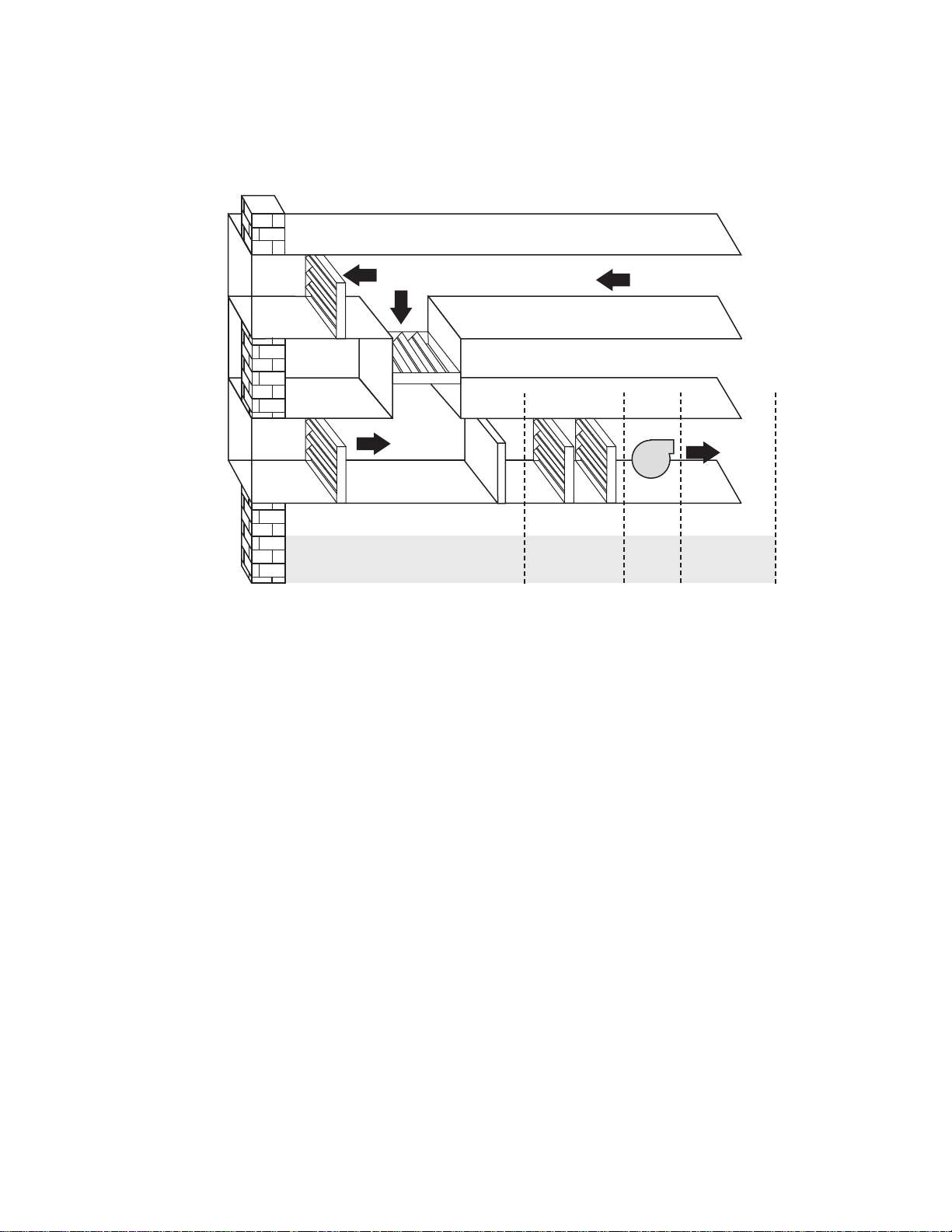
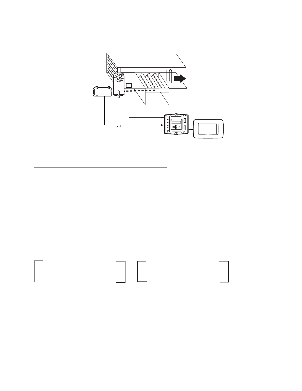
Air Handler Control Loops
DAMPER
EX.
AIR
RETURN AIR
FROM ROOM
O.A.
DAMPER
MIXED
AIR
MIXED AIR
SECTION
There are typically four sections of an air
handler. The Mixed Air Section is where
return air and outside air are combined
(mixed). Note some systems’ fans may be
100% return air or 100% outside air and will
not have a mixed air section.
The Conditioning Section commonly
contains filtration, heating, cooling and
humidification. The filters and heating and
cooling coils are located in the conditioning
section of the air handler.
DAMPER
FILTERS
HEATING COIL
SUPPLY
AIR TO
BUILDING
COOLING COIL
CONDITIONING
SECTION
FAN
FAN
SECTION
TERMINAL
SECTION
M23889A
In the Fan Section on the air handler shown
there is a supply fan. On other air handlers
there may be a return or exhaust fan. The
supply fan on this unit is referred to as a pullthrough because it is located on the outlet of
the coils. If it were located in front of the coils
then it would be a push-through fan.
The Terminal Section is composed of all the
components between the central fan and the
zones.
9 Honeywell Economizers 63-8594-02
Page 16

Section 1 - Ventilation
BUILDING
IS HIGHER THAN 70˚F (21 C)
EXHAUST
AIR
Basic Economizer Control
DAMPER
RETURN AIR
FROM ROOM
DAMPER
DAMPER
MOTOR
DAMPER
LINKAGE
OUTSIDE
AIR
120
F
110
130
100
140
90
15
80
16
70
100
80
120
60
40
140
°F
PROPORTIONAL
MINIMUM POSITION
CONTROL FOR
OUTSIDE AIR
DAMPERS
ECONOMIZER TWO-POSITION
HIGH LIMIT. CLOSES OUTSIDE
AIR DAMPERS TO MINIMUM WHEN
OUTSIDE AIR TEMPERATURE
170
60
180
Shown is the most basic temperature based
economizer control configuration. An
averaging element mixed air controller with
the sensing element is located in the duct
before the cooling or heating coils and
maintains the mixed air at 55°F (13°C). A two
position limit controller with sensing element in
outdoor air is used to close the outside air
dampers to a minimum position if the outdoor
air temperature is too warm to use for cooling.
There is a minimum position control on most
air handlers. The function of this control is to
ensure proper ventilation. The control provides
adjustable damper positioning between 0 and
100%. The outdoor damper position must be
set for minimum ventilation requirements
based on building occupancy as defined by
state or local code.
TR
TR1
BC
S
+
O
A
D
H705
S
R
+
5
2
1
ENTHALPY
4
3
X
CONTROL
D
6
SUPPLY
AIR TO
120
F
110
130
100
140
90
15
80
16
70
170
60
180
PROPORTIONAL MIXED
AIR CONTROLLER.
SETPOINT 55˚F (13 C)
M23916A
NOTE: A setting of 25% does not produce
25% airflow because the flow through
dampers is nonlinear.
It is important to know how much outside air is
being brought into a building through the
outdoor dampers on the air handlers. When
the return and mixed air temperatures can be
measured there is a formula used to calculate
the settings that will provide the desired
quantity of outside air.
Using the formula Vbz = Vp we know the total
ventilation and volume required. A second
formula is used to calculate the mixed air
temperature when the outside air temperature,
the return air temperature and the required
percentage of outside air are known.
Honeywell Economizers 63-8594-02 10
Page 17
Mixed Air Formulas
M23917A
MIXED
AIR
SENSOR
ECONOMIZER
“OA”
“MA”
“RA”
C7400S
SENSOR
MS3103
ACTUATOR
COMMERCIAL
THERMOSTAT
Section 1 - Ventilation
Return Air
Temperat ure
Return Air
Temperat ure
_
_
Mixed Air
Temperature
Outdoor Air
Temperature
Formula for Measuring the Percentage of Outside Air in an Air Handler.
This formula is used to determine the
percentage of outside air (by volume) being
brought into a building from the outside. The
OA dampers can be adjusted by measuring
the MA, OA and RA to balance the correct
Vbz. It is a test that should be conducted
during routine maintenance to ensure that the
Return Air
Temperature
X
% of
Return
Air
Outside Air
+
Temperature
Formula for Adjusting the Minimum Position Control.
x 100% =
Volume (%) of
Outside Air
correct percentage of ventilation is being
provided. Note the fan must be running with
the panels on the unit to take these
measurements. Drill a hole in the side of the
unit and insert temperature probe to measure
the MA temperature. The hole must be sealed
when measurements are completed.
X
% of
Outside
Air
Temperature
=
of Mixed Air
This formula is used to make adjustments to
the mixed air controls. In ASHRAE 62.1 there
are two components of the percent of outdoor
air ventilation required, the human component
and the buildings effluent component. The
rates in the standard are based on the type of
human activity normally performed in the
building. For example: the base rate for office
buildings is 5 cfm per person and the building
effluent rate is 0.06 cfm per square foot of
space. Initially only two temperatures are
measured, return and outside air. The
minimum position control is then adjusted until
the mixed air temperature is equal to the result
of the formula. For design requirements for
CFM per person for all building types, refer to
ASHRAE standard 62.1 section 6 and/or local
or state building codes.
11 Honeywell Economizers 63-8594-02
Page 18
Section 1 - Ventilation
OUTSIDE AIR TEMPERATURE
MIXED and RETURN AIR TEMPERATURES
0%
10%
20%
30%
40%
50%
60%
70%
80%
90%
100%
0%
10%
20%
30%
40%
50%
60%
70%
80%
90%
100%
%
O
U
T
S
I
D
E
A
I
R
%
O
U
T
S
I
D
E
A
I
R
49 C
120 F
43
110
38
100
32
90
27
80
21
70
16
60
10
50
4
40
-1
30
-7
20
-12
10
-18
0
-23
-10
-29 C
-20 F
120 F
49 C
110
43
100
38
90
32
80
27
70
21
60
16
50
10
40
4
30
-1
20
-7
10
-12
0
-18
-10
-23
-20 F
-29 C
M25274A
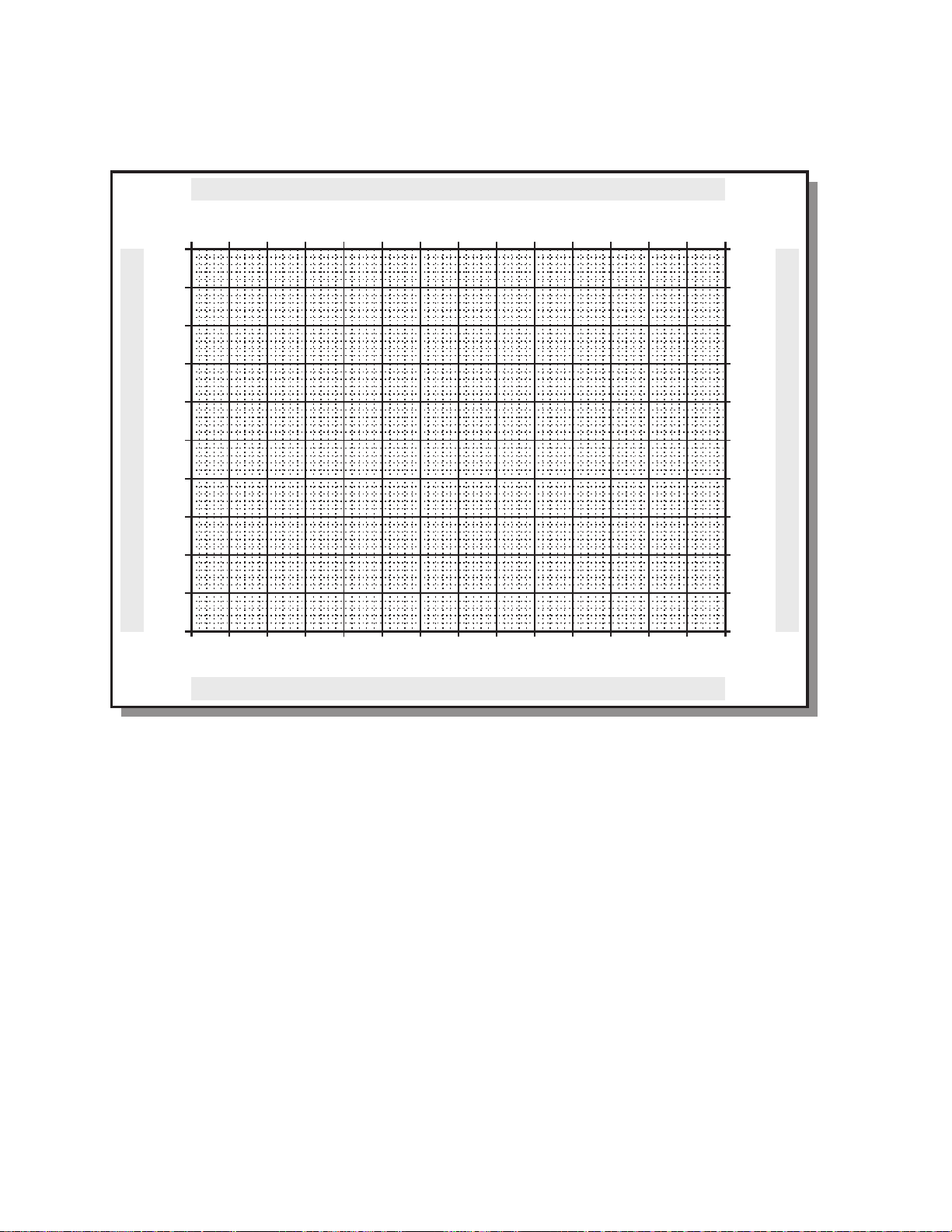
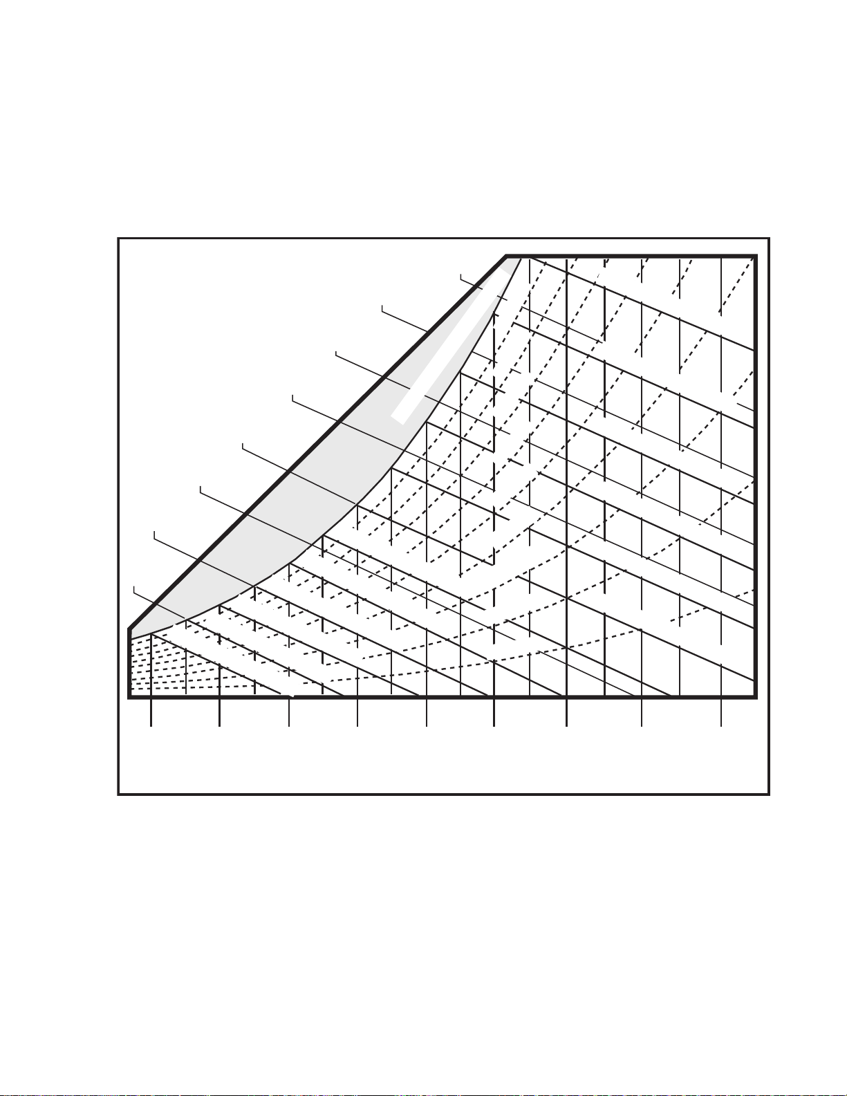
Outside Air Percentage Chart
This chart can also be used for measuring the
percentage of outside air on an air handler.
The same three temperatures are measured
per the formulas on the preceding page. Lines
are drawn on the chart using a ruler. As with
the formulas this chart is most effective if there
is at least a 10 degree F difference between
the return and outside air. This will typically
require either a warm or cold day rather than
moderate weather. It is more accurate to
measure outside air percentage on a day
Honeywell Economizers 63-8594-02 12
when the outside temperature is 10°F (-12°C)
rather than on a day when it is 70°F (21°C). If
the temperature difference between the return
and outside air is only a few degrees, a small
error in measurements can alter the results by
as much as 50% using this method. If the
temperature difference is 40 or 50°F (22 or
28°C) small errors in measurement do not
substantially affect the results of the
calculations.
Page 19
Example 1: Using the Outside Air Percentage Chart
OUTSIDE AIR TEMPERATURE
MIXED and RETURN AIR TEMPERATURES
0%
10%
20%
30%
40%
50%
60%
70%
80%
90%
100%
0%
10%
20%
30%
40%
50%
60%
70%
80%
90%
100%
%
O
U
T
S
I
D
E
A
I
R
%
O
U
T
S
I
D
E
A
I
R
49 C
120 F
43
110
38
100
32
90
27
80
21
70
16
60
10
50
4
40
-1
30
-7
20
-12
10
-18
0
-23
-10
-29 C
-20 F
120 F
49 C
110
43
100
38
90
32
80
27
70
21
60
16
50
10
40
4
30
-1
20
-7
10
-12
0
-18
-10
-23
-20 F
-29 C
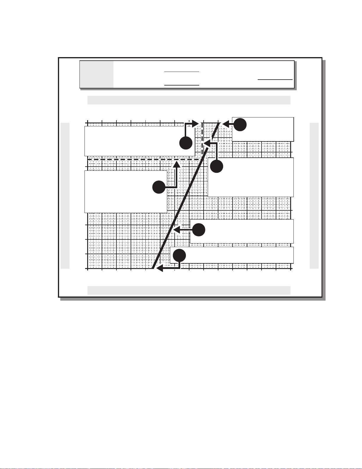
Draw a line straight
down from the mixed air
temperature till it
intersects the line that
was just drawn.
Draw a line from the return
air on top to the outside air on
the bottom.
Measure the outside air temperature.
At the point of
intersection draw a
line to the left till the
percentage of outside
air is indicated.
Measure the mixed air
temperature. This should be
done in 4 or more locations and
averaged.
6
4
3
70 F (21 C)
1
Measure the
return air
temperature.
2
5
RETURN AIR TEMP
MIXED AIR TEMP
OUTSIDE AIR TEMP
OUTSIDE
AIR
CHART
59 F
(15 C)
25 F (-4 C)
M25275A
Section 1 - Ventilation
1. Measure the return air temperature.
2. Measure the outside air temperature.
3. Draw a line from the return air
temperature to the outside air
temperature.
4. Measure the mixed air temperature in
multiple locations and determine the
average.
5. Draw a line down from the mixed air
temperature to the point where it
intersects the first line.
6. Draw a line from the point of intersection
to the outside air percentage on the left
side of the chart.
According to the results from this chart this air
handler is supplied with 26% outside air. If the
total supply volume is 20,000 cubic feet per
minute (cfm) (566 m3/min) then:
0.26 X 20,000 cfm of total supply air equals
5,200 cfm of outside air (147 m3/min).
This indicates that when the measurements
were done on this air handler the total volume
of outside air in the mixed air was 5,200 cfm of
outside air (147 m3/min).
13 Honeywell Economizers 63-8594-02
Page 20
Section 1 - Ventilation
OUTSIDE AIR TEMPERATURE
MIXED and RETURN AIR TEMPERATURES
0%
10%
20%
30%
40%
50%
60%
70%
80%
90%
100%
0%
10%
20%
30%
40%
50%
60%
70%
80%
90%
100%
%
O
U
T
S
I
D
E
A
I
R
%
O
U
T
S
I
D
E
A
I
R
49 C
120 F
43
110
38
100
32
90
27
80
21
70
16
60
10
50
4
40
-1
30
-7
20
-12
10
-18
0
-23
-10
-29 C
-20 F
120 F
49 C
110
43
100
38
90
32
80
27
70
21
60
16
50
10
40
4
30
-1
20
-7
10
-12
0
-18
-10
-23
-20 F
-29 C
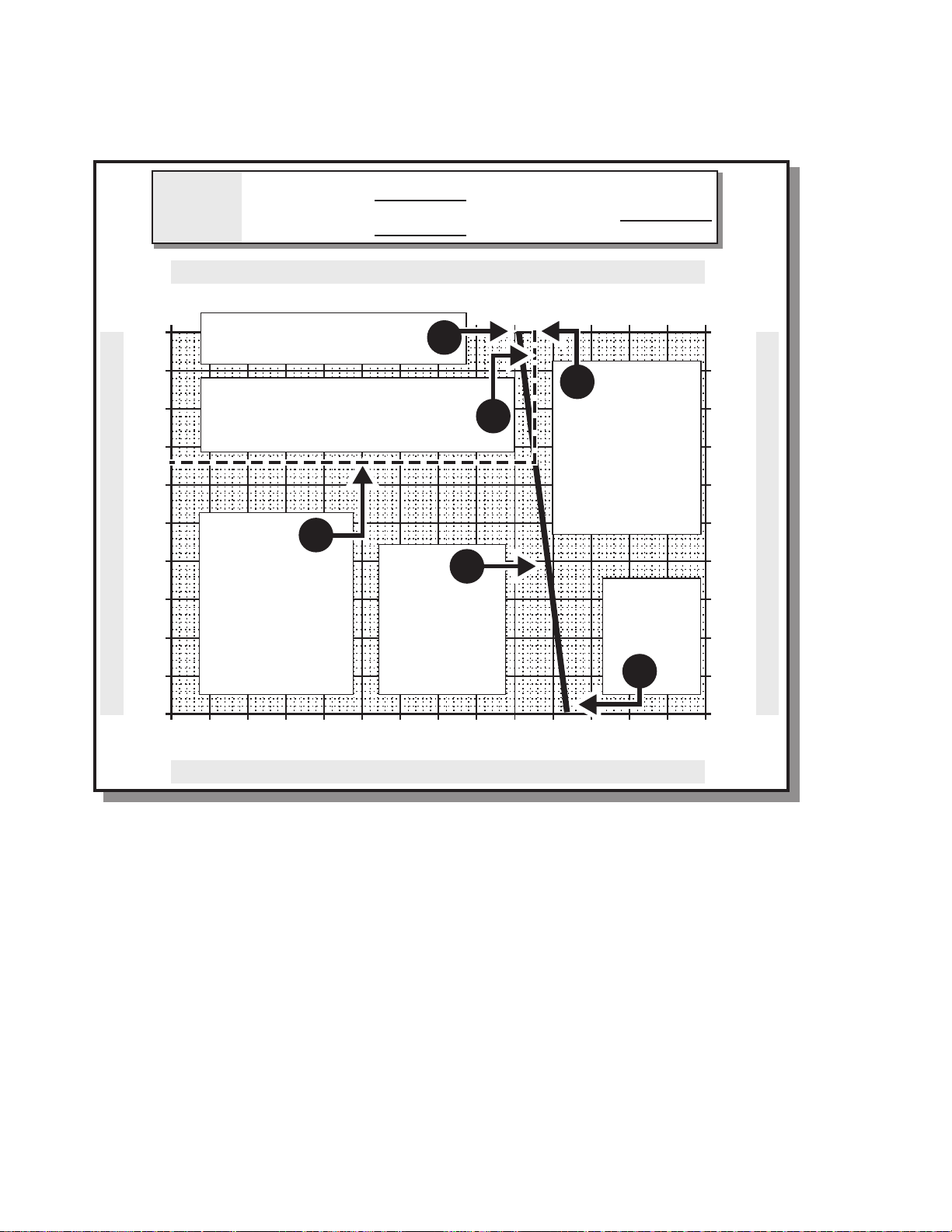
Measure the return air
temperature.
1
Measure the
outside air
temperature.
2
Draw a line
from the return
air on top to the
outside air on
the bottom.
3
Measure the mixed
air temperature.
This should be
done in 4 or more
locations and
averaged.
4
Draw a line straight down from the
mixed air temperature till it intersects
the line that was just drawn.
At the point of
intersection draw a
line to the left till
the percentage of
outside air is
indicated.
6
71 F (22 C)
RETURN AIR TEMP
MIXED AIR TEMP
OUTSIDE AIR TEMP
OUTSIDE
AIR
CHART
75 F
(24 C)
84 F (29 C)
5
M25276A
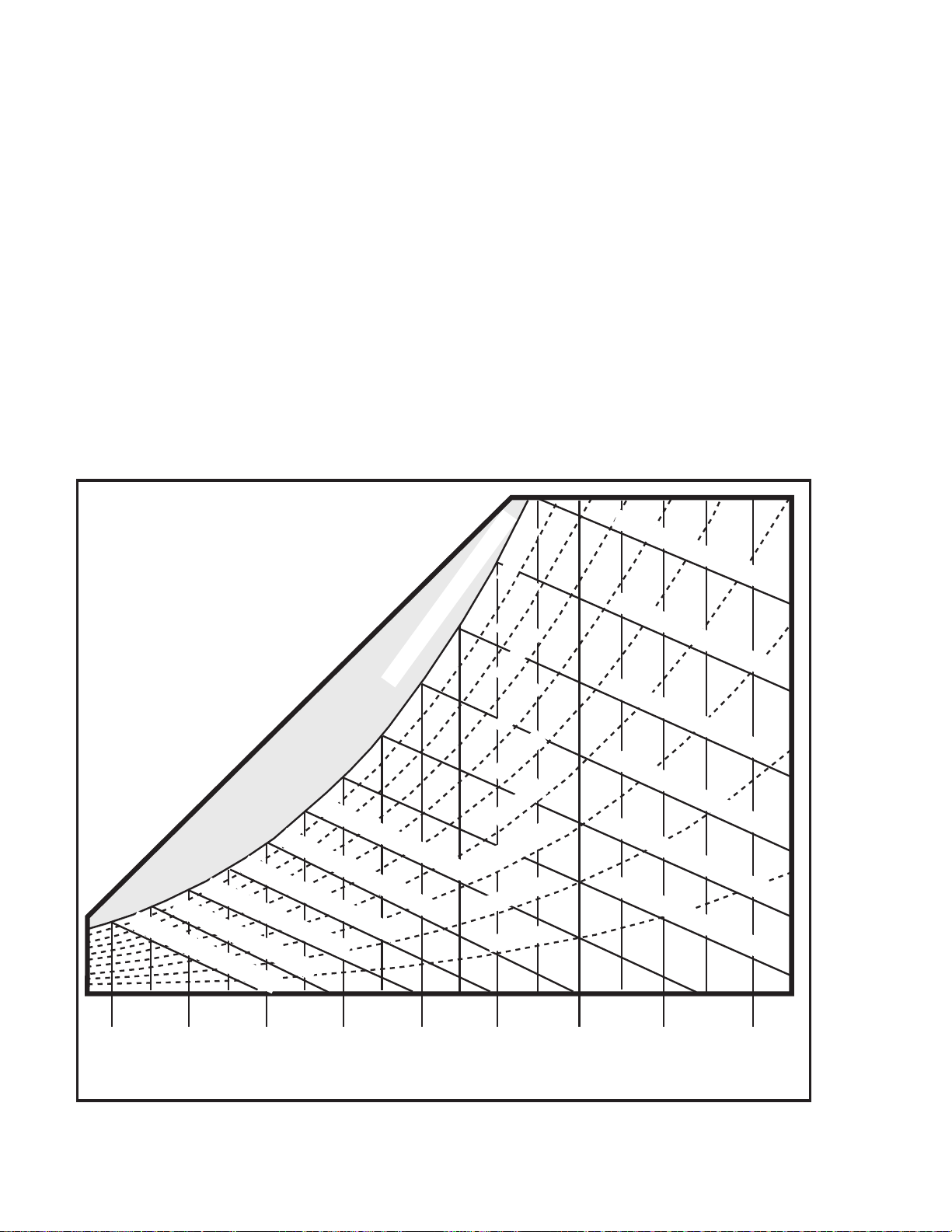
Example 2: Use of Outside Air Chart on a Warm Day
The chart can also be used on a warm day
when the outside air temperature exceeds
both the return and the mixed air
temperatures. The first line drawn will slant in
a different direction. Once again it is best to do
this test when there is a minimum of 10
degrees F difference between the outside and
return air.
Honeywell Economizers 63-8594-02 14
Page 21
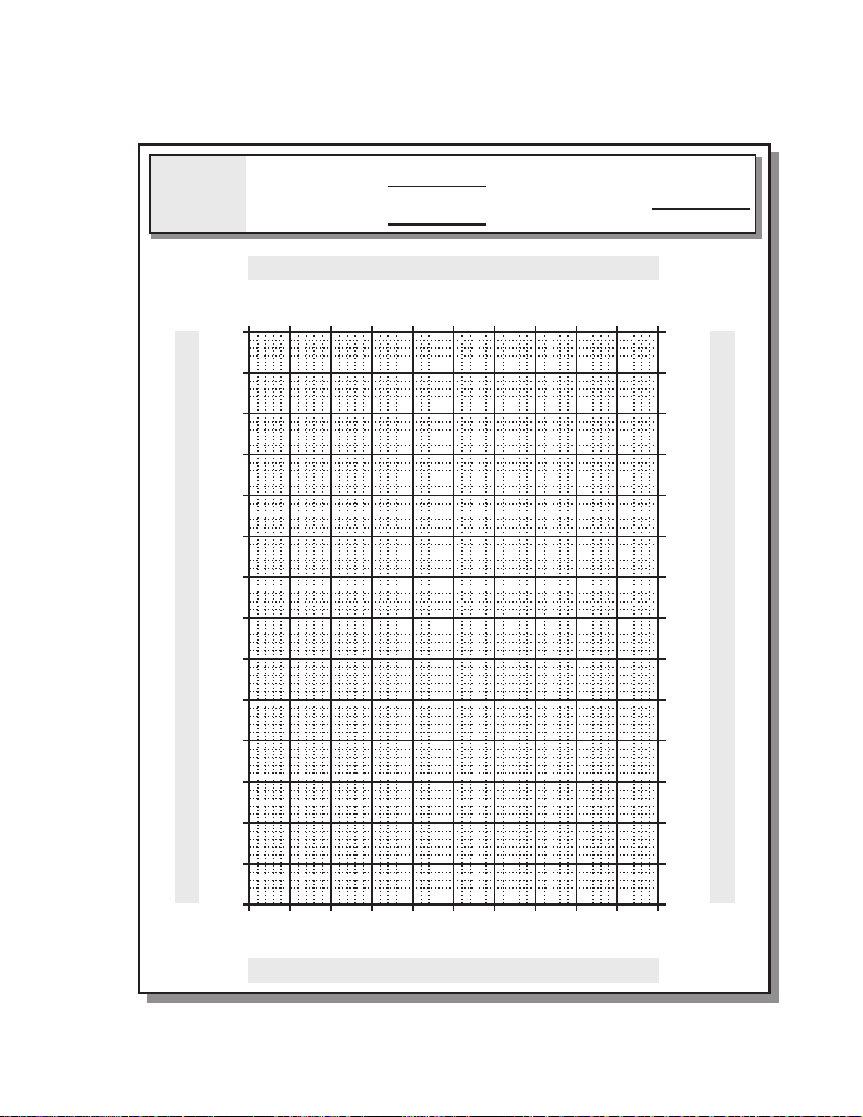
Extra Outside Air Percentage Chart
Section 1 - Ventilation
OUTSIDE
AIR
CHART
C 92-
F 02-
01-
32-
0
81-
01
21-
7-
02
1-
03
4
04
MIXED AIR TEMP
OUTSIDE AIR TEMP
R
I
%08
%09
%001
RETURN AIR TEMP
O
A
%07
D
E
%06
S
I
%05
U
T
%03
%04
%
%0
%01
%02
C 92-
F 02-
32-
01-
0
81-
MIXED and RETURN AIR TEMPERATURES
01
21-
7-
02
1-
03
4
04
OUTSIDE AIR TEMPERATURE
05
01
06
61
07
12
08
72
09
23
83
001
34
011
C 94
F 021
%06
%07
%08
%09
%001
R
A
I
E
D
01
05
61
06
12
07
72
08
23
09
83
001
34
011
C 94
F 021
%0
%01
%02
%03
%04
%05
O
U
T
S
I
%
M25277A
15 Honeywell Economizers 63-8594-02
Page 22
Section 1 - Ventilation
A
Example 3: Minimum Ventilation Adjustment
EXHAUST
AIR
OUTSIDE
IR
30˚F (-1 C)
DAMPER
1. Specifications:
Office space - 100,000 ft
2
Air handler capacity 20,000 cfm
(566 m3/min.)
People in area - 250
2. Ventilation (VOT) required:
= 250 x 5 cfm + 0.06 cfm/ft2 x 100,000 ft
= 1250 cfm + 6000 cfm
= 7250 cfm
Where Vat = 0.06 cfm/ft2 x 100,000 ft2.
Therefore Vat = 6000 cfm
DAMPER
2
RETURN
AIR
73˚F (23 C)
M23910
3. Ventilation percentage:
7250 cfm (205.3 m3/min)/20,000 cfm
(570 m3/min)
VOT maximum position= 36%
6000 cfm (169.9 m3/min)/20,000 cfm
(570 m3/min)
VOT Minimum position= 30%
4. Measure the return air temperature:
73°F (23°C).
5. Measure the outside air temperature:
30°F (-1°C).
This example shows a procedure for adjusting
the DCV maximum and minimum positions.
Honeywell Economizers 63-8594-02 16
Page 23
M23918A
SUPPLY
ADJUST THIS SETTING
OUTSIDE
AIR
30˚F (-1 C)
RETURN
AIR
73˚F (23 C)
Section 1 - Ventilation
FILTERS
Return Air
Temperature
X
+
S
COMMERCIAL
THERMOSTAT
% of
Return
Air
Outside Air
+
Temperature
SUPPLY OR
MIXED AIR
SENSOR
X
COILS
FAN
% of
Outside
Air
UNTIL THE MIXED AIR
IS 62.5˚F (17 C)
AIR
Temperature
=
of Mixed Air
6. Use the mixed air temperature formula or the graph to determine the Demand Control
Ventilation maximum MAT:
73°F (23°C) X 64% + 30°F (-1°C) X 36% =
Temperature of
Mixed Air
46.7°F (8.2°C) + 10.8°F (-11.8°C) 57.5°F (14.2°C)
7. Use the mixed air temperature formula or the graph to determine the minimum position MAT:
73°F (23°C) X 60% + 30°F (-1°C) X 30% =
43.8°F (8.2°C) + 12°F (-11°C) 55.8°F (13.2°C)
8. Close the outside air dampers. The
method used for this depends upon the
controller being used.
9. When using analog economizers, turn the
DCV maximum position control (pot) until
the measured mixed air temperature is
57.5°F (14.2°C). When using the JADETM
controller, go to the set point menu and
adjust the Vent max setting and the up
and down arrows on the keypad.
10. Mark this setting on the control as being
11. Close the outside air dampers. On the
analog economizers, turn the minimum
position control (pot) until the measured
mixed air temp is 55.8 °F (13.2°C). When
using the JADETM controller, go to the set
point menu and adjust the Vent min
setting using the up and down arrows on
the keypad.
12. Mark this setting on the control as being
30% outdoor air.
Temperature of
Mixed Air
36% outdoor air.
17 Honeywell Economizers 63-8594-02
Page 24
Section 1 - Ventilation
A
Example 4: Ventilation Review Questions
EXHAUST
AIR
DAMPER
OUTSIDE
IR
21˚F (-6 C)
1. Specifications:
Office space - 200,000 ft2.
Air handler capacity - 30,000 cfm
(849 m3/min)
People in area - 350
2. Ventilation required:
=350 x 5 cfm per person + 0.06 cfm/ft2 x
200,000 ft
2
=1750 cfm + 12,000 cfm
=13750 cfm
RETURN
AIR
68˚F (20 C)
30,000 CFM
3
MIN.)
(849 M
M23920
4. Measure the return air temperature:
68°F (20°C)
5. Measure the outside air temperature:
21°F (-6°C)
This is the air handler for an office building
with 350 people maximum occupancy.
Complete the required steps in the procedure
to adjust the controls for the correct volume of
ventilation.
3. Ventilation percentage:
13750 cfm (389.4 m3/min)/30,000 cfm
(849 m3/min)
Honeywell Economizers 63-8594-02 18
Page 25
M23919B
SUPPLY
OUTSIDE
AIR
21˚F (-6 C)
RETURN
AIR
68˚F (20 C)
Section 1 - Ventilation
FILTERS
+
S
SUPPLY OR
MIXED AIR
SENSOR
ADJUST THIS SETTING
UNTIL THE MIXED AIR
IS ___˚F (___ C)
% of
Return Air
Temperature
X
Return Air
COMMERCIAL
THERMOSTAT
% of
Outside Air
+
Temperature
CONTROLLER
X
Outside Air
6. Use the mixed air temperature formula or the graph:
68°F (20°C) X ____% + 21°F (-6°C) X ____% =
_____°F (____°C) + _____°F (_____C) _____°F (____°C)
AIR
Temperature
=
of Mixed Air
Temperature of
Mixed Air
NOTE: Note use this formula to determine
DCV maximum MAT and Minimum
position MAT.
7. Close the outside air dampers to the
minimum position.
The method used for this depends upon
the controller being used.
8. On analog economizers, turn the DCV
maximum control (potentiometer) until the
measured mixed air temperature is
_____°F (_____°C). When using the
JADETM controller, go to the set point
menu and adjust the Vent max setting
using the up and down arrows on the
keypad.
9. Mark this setting on the control as being
36% outdoor air.
10. On analog economizers, turn the
minimum position until the measured
mixed air temperature is _____°F
(_____°C). When using the JADETM
controller, go to the set point menu and
adjust the Vent min setting using the up
and down arrows on the keypad.
11. Mark this setting on the control as being
_____% outdoor air.
12. Restore all settings and setpoints.
19 Honeywell Economizers 63-8594-02
Page 26
Section 1 - Ventilation
Economizer Cycle Definition
ECONOMIZER CONTROLLER
SINGLE STAGE COOLING
FIRST
STAGE COOL
Y1
SECOND
Y2
STAGE COOL
COMMERCIAL THERMOSTAT
On a First Call for Cooling From
Commercial Thermostat (Y1)
Controller signal is routed to the economizer
logic module.
IF THE OUTDOOR AIR IS SUITABLE FOR
FREE COOLING:
YES
OUTSIDE
AIR COOL?
OPEN OUTSIDE
NO
AIR DAMPER
MECHANICAL
COOL 1
COMPRESSOR
M13816A
hold the temperature between -1F and +1F of
the MAT setpoint. For example if the MAT is
set to 53F, the damper will hold between 52F
and 54F.
When the mixed or supply air goes below 50°F
(10°C) the damper is modulated towards
closed (52°F for JADETM in our example).
With analog economizers the actuator
modulates the outdoor damper open until the
room temperature is cool enough to satisfy the
call for cooling and maintain the mixed or
discharge air between 50 and 55°F (10 and
13°C). With the JADETM controller the actuator
modulates the OA damper open to maintain
the MAT setpoint. The MAT default is 53F with
a 2F differential. The MAT setpoint can be
changed in the menu using the up and down
arrows on the JADETM.
When the mixed or discharge air is between
50 and 55°F (10 and 13°C) the actuator will
hold damper position with analog
economizers, with JADETM the actuator will
Honeywell Economizers 63-8594-02 20
When the mixed or supply air goes above
56°F (13°C) the damper is modulated towards
open (54°F for JADE
TM
in our example).
For the analog economizers the MAT setpoint
is not adjustable, the range can be changed
using external resistance. For the JADETM, the
MAT is adjustable between 38°F and 70°F.
IF THE OUTDOOR AIR IS NOT SUITABLE
FOR FREE COOLING:
The first stage of the cooling compressor is
turned on and the dampers are set to
minimum for occupancy requirements (Vat if
using DCV, VOT if no DCV).
Page 27
Single and Two Stage Cooling With Economizer
Y2
Y1
SECOND
STAGE COOL
FIRST
STAGE COOL
OUTSIDE
AIR COOL?
YES
NO
OPEN OUTSIDE
AIR DAMPER
COMPRESSORS
MECHANICAL
COOL 1
M13817A
TWO STAGE COOLING
MECHANICAL
COOL 2
COMMERCIAL THERMOSTAT
ECONOMIZER CONTROLLER
Section 1 - Ventilation
On a Call for Second Stage Cooling
Controller signal is routed to the economizer
logic module.
IF THE OUTDOOR AIR IS SUITABLE FOR
FREE COOLING AND THE OUTSIDE AIR
DAMPERS ARE OPEN:
The economizer logic turns on the first stage
of mechanical cooling for the second stage of
cooling required by the commercial
thermostat. With JADETM the actuator drives
the OA damper wide open to try to satisfy the
call for second stage of cooling. If OA
dampers are 100% open and call for second
stage is not satisfied then the JADETM will turn
on the second stage mechanical cooling and
the OA damper will remain wide open.
NOTE: JADETM has an option in the
Advanced setup menu "STG3 DLY"
which is a delay after the stage 2 for
cooling has been active for a
programmed amount of time. If the
space has not been satisfied after the
programmed amount of time, the
JADETM turns on the 2nd stage of
mechanical cooling to allow 3 stages
of cooling, 1 economizer and 2
mechanical. This feature can also be
turned off.
IF THE OUTDOOR AIR IS NOT SUITABLE
FOR FREE COOLING:
The first stage cooling compressor is on, and
the logic module turns on the second stage of
mechanical cooling.
NOTE: A commercial thermostat with a
minimum of two stages of cooling is
required. The first stage must be
available for economizing if outside air
is suitable.The OA dampers must be
opened completely on a second call
for cooling before the mechanical
cooling is turned on.
21 Honeywell Economizers 63-8594-02
Page 28

Section 1 - Ventilation
Honeywell Economizers 63-8594-02 22
Page 29
Section 2 - Enthalpy Theory And Controllers
40 F
4 C
50 F
10 C
60 F
16 C
70 F
21 C
80 F
27 C
90 F
32 C
100 F
38 C
110 F
43 C
120 F
49 C
35 F
2 C
45 F
7 C
55 F
13 C
65 F
18 C
75 F
24 C
85 F
29 C
95 F
35 C
105 F
41 C
115 F
46 C
F 0 9
) C 2 3 (
B L U B T E W
F 5 8
) C 9 2 (
B L U B T E W
F 0 8
) C 7 2 (
B L U B T E W
F 5 7
) C 4 2 (
B L U B T E W
F 0 6
) C 6 1 (
B L U B T E W
F 5 5
) C 3 1 (
B L U B T E W
F 0 5
) C 0 1 (
B L U B T E W
5 4
F
(
7
) C
B L U B T E W
0 4
F
(
4
) C
B L U B T E W
5 3
F
(
2
) C
B L U B T E W
H R % 0 8
H R % 0 7
H R % 0 3
H R % 0 4
H R % 0 5
H R % 0 6
H R % 0 9
H R % 0 1
H R % 0 2
H R % 0 0 1 - N O I T A R U T A S
F 0 7
) C 1 2 (
B L U B T E W
F 5 6
) C 8 1 (
B L U B T E W
DRY BULB TEMPERATURES
15
BTU/LB
34.8 kJ/kg
20 BTU/LB
46.4 k-J/kg
25 BTU/LB
58 k-J/kg
30 BTU/LB
69.7 k-J/kg
35 BTU/LB
81.4 k-J/kg
40 BTU/LB
92.8 k-J/kg
45 BTU/LB
104.5 k-J/kg
50 BTU/LB
116 k-J/kg
M25280
Section 2 - Enthalpy Theory And Controllers
23 Honeywell Economizers 63-8594-02
Page 30
Section 2 - Enthalpy Theory And Controllers
40 F
4 C
50 F
10 C
60 F
16 C
70 F
21 C
80 F
27 C
90 F
32 C
100 F
38 C
110 F
43 C
120 F
49 C
35 F
2 C
45 F
7 C
55 F
13 C
65 F
18 C
75 F
24 C
85 F
29 C
95 F
35 C
105 F
41 C
115 F
46 C
F 0 9
) C 2 3 (
B L U B T E W
F 5 8
) C 9 2 (
B L U B T E W
F 0 8
) C 7 2 (
B L U B T E W
F 5 7
) C 4 2 (
B L U B T E W
F 0 6
) C 6 1 (
B L U B T E W
F 5 5
) C 3 1 (
B L U B T E W
F 0 5
) C 0 1 (
B L U B T E W
5 4
F
(
7
) C
B L U B T E W
0 4
F
(
4
) C
B L U B T E W
5 3
F
(
2
) C
B L U B T E W
H R % 0 8
H R % 0 7
H R % 0 3
H R % 0 4
H R % 0 5
H R % 0 6
H R % 0 9
H R % 0 1
H R % 0 2
H R % 0 0 1 - N O I T A R U T A S
F 0 7
) C 1 2 (
B L U B T E W
F 5 6
) C 8 1 (
B L U B T E W
DRY BULB TEMPERATURES
M25278
The Psychrometric Chart
This is a psychrometric chart. To use the chart
effectively the thermodynamic properties of air
must be known. Some common terms are:
Dry Bulb Temperature
The temperature read directly on an ordinary
thermometer.
Wet Bulb Temperature
The temperature read on a thermometer
whose bulb is encased in a wet wick and with
air blown across the wick at 900 ft. per minute
(274 meters per minute). The evaporation of
the water causes the temperature to drop, this
may also be referred to as the “evaporation
effect.” When the temperature stops falling
that is the wet bulb temperature. The sling
psychrometer is a common instrument used to
determine the wet bulb temperature although
there are other methods now available.
Dry bulb and wet bulb are the two most readily
measurable variables on the chart and when
known can be used to determine all other
properties on the psychrometric chart.
63-8594-02 Honeywell Economizers 24
Page 31

Section 2 - Enthalpy Theory And Controllers
40 F
4 C
50 F
10 C
60 F
16 C
70 F
21 C
80 F
27 C
90 F
32 C
100 F
38 C
110 F
43 C
120 F
49 C
35 F
2 C
45 F
7 C
55 F
13 C
65 F
18 C
75 F
24 C
85 F
29 C
95 F
35 C
105 F
41 C
115 F
46 C
F 0 9
) C 2 3 (
B L U B T E W
F 5 8
) C 9 2 (
B L U B T E W
F 0 8
) C 7 2 (
B L U B T E W
F 5 7
) C 4 2 (
B L U B T E W
F 0 6
) C 6 1 (
B L U B T E W
F 5 5
) C 3 1 (
B L U B T E W
F 0 5
) C 0 1 (
B L U B T E W
5 4
F
(
7
) C
B L U B T E W
0 4
F
(
4
) C
B L U B T E W
5 3
F
(
2
) C
B L U B T E W
H R % 0 8
H R % 0 7
H R % 0 3
H R % 0 4
H R % 0 5
H R % 0 6
H R % 0 9
H R % 0 1
H R % 0 2
H R % 0 0 1 - N O I T A R U T A S
F 0 7
) C 1 2 (
B L U B T E W
F 5 6
) C 8 1 (
B L U B T E W
DRY BULB TEMPERATURES
M25279
Relative Humidity and Saturation
Relative Humidity
Relative Humidity is the ratio of the measured
amount of moisture in the air to the maximum
amount of moisture the air can hold at the
same temperature and pressure. Relative
humidity is expressed in percent of saturation.
Air with a relative humidity of 35%, for
example, is holding 35 percent of the moisture
that it is capable of holding at that temperature
and pressure.
Saturation
The point at which the relative humidity
reaches 100% and no more moisture can be
contained in the air is the saturation point. The
relative humidity and saturation lines are the
only curved lines on this psychrometric chart.
25 Honeywell Economizers 63-8594-02
Page 32

Section 2 - Enthalpy Theory And Controllers
40 F
4 C
50 F
10 C
60 F
16 C
70 F
21 C
80 F
27 C
90 F
32 C
100 F
38 C
110 F
43 C
120 F
49 C
35 F
2 C
45 F
7 C
55 F
13 C
65 F
18 C
75 F
24 C
85 F
29 C
95 F
35 C
105 F
41 C
115 F
46 C
F 0 9
) C 2 3 (
B L U B T E W
F 5 8
) C 9 2 (
B L U B T E W
F 0 8
) C 7 2 (
B L U B T E W
F 5 7
) C 4 2 (
B L U B T E W
F 0 6
) C 6 1 (
B L U B T E W
F 5 5
) C 3 1 (
B L U B T E W
F 0 5
) C 0 1 (
B L U B T E W
5 4
F
(
7
) C
B L U B T E W
0 4
F
(
4
) C
B L U B T E W
5 3
F
(
2
) C
B L U B T E W
H R % 0 8
H R % 0 7
H R % 0 3
H R % 0 4
H R % 0 5
H R % 0 6
H R % 0 9
H R % 0 1
H R % 0 2
H R % 0 0 1 - N O I T A R U T A S
F 0 7
) C 1 2 (
B L U B T E W
F 5 6
) C 8 1 (
B L U B T E W
DRY BULB TEMPERATURES
15
BTU/LB
34.8 kJ/kg
20 BTU/LB
46.4 k-J/kg
25 BTU/LB
58 k-J/kg
30 BTU/LB
69.7 k-J/kg
35 BTU/LB
81.4 k-J/kg
40 BTU/LB
92.8 k-J/kg
45 BTU/LB
104.5 k-J/kg
50 BTU/LB
116 k-J/kg
M25280
Enthalpy
The measure of heat used in the United States
today is the British Thermal Unit or BTU. This
is the amount of heat required to raise the
temperature of one pound of water by one
degree Fahrenheit. A metric unit is the joule.
There are 1055 joules per BTU.
Sensible Heat
Heat that changes the temperature of the air
without changing its moisture content or dew
point temperature is sensible heat. Heat
added by a heating coil is sensible heat. Heat
removed by a cooling coil that remains dry is
also sensible heat.
Latent Heat
Heat required to change water to vapor
(steam) without change in temperature or
pressure is latent heat. It is also called heat of
vaporization. When water is vaporized the
latent heat passes into the air, and when vapor
condenses, latent heat is removed.
Total Heat (Enthalpy)
The sum of sensible and latent heat and is
commonly referred to as enthalpy. Enthalpy is
often referred to as the total heat content of
the air.
63-8594-02 Honeywell Economizers 26
Page 33

Section 2 - Enthalpy Theory And Controllers
Psychrometric Chart of
Enthalpy Economizer Control
A standard dry bulb economizer discussed
earlier causes the air handler to switch over
from outside air to return air at the setpoint of
the outside air high limit. This will vary based
on the climate. According to ASHRAE 90.1,
the changeover temperatures for the US are
65F, 70F and 75F based on the region of the
country. Dry bulb economizers only control the
outside air dampers based on temperature. If
it is a cool but rainy day, the outside air will be
brought in and extra cooling capacity will be
required to dehumidify it or the humidity will be
released into the ducts or occupied space.
Enthalpy economizers take temperature and
humidity into account. With enthalpy control,
humid air below a conventional dry bulb
temperature setpoint is locked out. Cooling
costs are lowered in most climates when using
enthalpy instead of dry bulb temperature with
the economizer.
27 Honeywell Economizers 63-8594-02
Page 34

Section 2 - Enthalpy Theory And Controllers
M23906A
SUPPLY
AIR TO
BUILDING
MIXED OR
SUPPLY AIR
SENSOR
FAN
COILS
W7220 ECONOMIZER
CONTROLLER
WITH DEMAND
CONTROL
VENTILATION
TB8220
COMMERCIAL
PRO
SINGLE SENSOR OR HIGH LIMIT ENTHALPY
COOLING AND HEATING CONTROLLED FROM COMMERCIAL
THERMOSTAT. ENTHALPY ECONOMIZER CONTROLLER
FUNCTIONS AS FIRST STAGE OF COOLING.
C7400S
ENTHALPY
SENSOR
C7400S ENTHALPY SENSORS ARE WIDELY USED WITH HONEYWELL
CONTROLLERS. IT COMBINES BOTH TEMPERATURE AND HUMIDITY
MEASUREMENTS INTO ONE DEVICE. TWO C7400A’S ARE NEEDED TO
PROVIDE DIFFERENTIAL ENTHALPY FOR ANALOG ECONOMIZERS AND
TWO C7400S SYLK-BUS SENSORS PROVIDE TEMPERATURE AND HUMIDITY
TO THE JADE FOR DIFFERENTIAL ENTHALPY.
OUTSIDE
AIR SENSOR
Single Sensor Enthalpy Control
There are two enthalpy control strategies
available: single and differential enthalpy
control.
The single enthalpy control uses one enthalpy
sensor located in the outdoor air in any
orientation that exposes it to freely circulating
air and protects it from rain, snow and direct
sunlight. The enthalpy sensor replaces the dry
bulb high limit used in a standard economizer.
Instead of switching the mixed air control loop
from outdoor to return air at a preset outdoor
air dry bulb temperature, on a call for cooling
from the controller or commercial thermostat
the economizer logic module compares the
outdoor enthalpy to a preselected setpoint.
The value of the setpoint is illustrated on the
psychrometric chart on page 57 with curves
labeled as A, B, C or D. The setpoint selected
will vary based on climate, activities in the
controlled area and the type of mechanical
equipment used to provide cooling. An
installer can choose a more aggressive
setpoint A for more free cooling or a
conservative setpoint D for less free cooling.
Care needs to taken to select the correct
curve for comfort and to control the humidity to
prevent indoor air quality and other issues
caused by high humidity in a building. The
mixed air sensor, located in the area where
the return and outdoor air mix, maintains the
mixed air temperature between 50 and 56°F
(10.0 and 12.8°C).
When using the JADE
TM
the analog curves are changed to control to
dry bulb temperature, enthalpy and dew point
based on ES boundaries as shown on
modified psychrometric chart and table on
page 57.
JADE
TM
controls to a +/-1F differential versus
the 50-55F range of an analog economizer.
63-8594-02 Honeywell Economizers 28
Page 35

Section 2 - Enthalpy Theory And Controllers
Two Sensor or Differential Enthalpy
A dual sensor enthalpy control is equipped
with the same outdoor air enthalpy sensor and
an additional second enthalpy sensor in the
return air. This is also referred to as differential
enthalpy. On a call for cooling or when the
mixed air temperature goes above the high
MAT range or setpoint, additional air with the
lower enthalpy, outdoor or return, is selected
to be brought into the conditioning section of
the air handler. For analog economizers the
setpoint on the logic module is turned to D
whenever differential enthalpy is used. This is
a very efficient method of controlling outdoor
air usage since the return and outside air
comparison is continuous and automatic year-
DUAL SENSOR OR DIFFERENTIAL ENTHALPY
DAMPER
EXHAUST
AIR
round. It eliminates operator error by
eliminating seasonal changeover which is
frequently overlooked. Though it may appear
wasteful to cool outdoor air at a higher dry
bulb temperature than return air, the savings
are verifiable through psychrometric
calculations. The amount of mechanical
cooling required to dehumidify air often
exceeds the amount required to lower the dry
bulb temperature. In buildings where there is a
substantial amount of cooking, laundry or
other moisture generating activity this type of
control sequence can result in substantial
savings in cooling costs.
RETURN AIR
SENSOR
RETURN AIR
FROM ROOM
OUTSIDE
AIR SENSOR
TB8220
COMMERCIAL
PRO
SUPPLY
AIR TO
BUILDING
MIXED OR
SUPPLY AIR
SENSOR
29 Honeywell Economizers 63-8594-02
COILS
FAN
W7220 ECONOMIZER
CONTROLLER
WITH DEMAND
CONTROL
VENTILATION
M23904A
Page 36

Section 2 - Enthalpy Theory And Controllers
M23905A
PRO
DIFFERENTIAL ENTHALPY WITH DCV
Enthalpy Control with Carbon Dioxide Sensor
Most building codes allow for the option of
carbon dioxide sensor-based demand control
ventilation (DCV) to determine the human
occupancy level of the space. Honeywell
supplied controllers that combined this
function with the economizer function. They
were the W7212, W7340, W7460, and the
W7215 economizer logic modules. All of these
logic modules had inputs for a room indoor air
content sensor. Additionally the W7215B was
available with outdoor air content sensor
inputs. The W7215 and W7212 were designed
to be used with series 72 actuators and the
W7460 with the M7415 actuator. The W7340
was designed to be used with an OEM system
because it requires external relays to switch to
compressor and communicates with the OEM
system controller via a modified modbus
protocol. In addition to the indoor sensor
based demand control ventilation option,
these logic modules had additional features
including:
• Maximum damper position adjustment
(DCV max).
• Exhaust fan setpoint.
• Occupied and Unoccupied operation.
• W7213 and W7214 are heat pump models.
The JADETM controller replaced the analog
economizers in new applications. The JADETM
is a digital economizer and incorporates many
features and functions that were not availably
on the analog sensors. See section 11 for the
JADETM controller.
DAMPER
EXHAUST
AIR
OUTSIDE
AIR SENSOR
+
S
TB8220
COMMERCIAL
DAMPER
+
RETURN
S
AIR SENSOR
MIXED OR
SUPPLY AIR
SENSOR
C7632 ROOM
CARBON DIOXIDE
SENSOR
COILS
RETURN AIR
FROM ROOM
FAN
W7212 ECONOMIZER
CONTROLLER
WITH DEMAND
CONTROL
VENTILATION
SUPPLY
AIR TO
BUILDING
63-8594-02 Honeywell Economizers 30
Page 37

Section 3 - Types of Analog Economizers
Section 3 - Types of Analog Economizers
There were a number of Honeywell analog
enthalpy economizer modules developed
since the early 1960s. Most can be replaced
by the JADETM controller. They varied based
on the actuator control series, mixed air
circuitry and enthalpy sensor configuration.
31 Honeywell Economizers 63-8594-02
Page 38

Section 3 - Types of Analog Economizers
Commercial
thermostat
Separate
Series
70 or 90
mixed air
controller
Mod IV actuator
Optional
second
enthalpy
sensor
H705 on plate,
one enthalpy
sensor on back
H705
The H705 was the base controller since the
mixed air circuitry was not included. Its
function was to provide SPDT high limit
switching in a separate mixed air control
circuit, typically series 90. It replaced the H205
without substantial wiring modifications and
could also be used in control circuits with other
company’s devices if a SPDT economizer high
limit was applicable.
63-8594-02 Honeywell Economizers 32
Page 39

W7459
Commercial
thermostat
One enthalpy or dry bulb and
one mixed/supply air sensor
required. Second enthalpy
sensor optional.
W7459 install
on actuator
M7405, M7415
or M8405
actuators
only
Section 3 - Types of Analog Economizers
The W7459 was similar to the H705 in that
only the enthalpy high limit function is provided
and the mixed air control circuit is in the
M7415 actuator. This restricted the W7459
use to the M7415, M7405 and M8405
actuators and it installed directly onto them.
Unlike the H705 there was not a sensor built
into the W7459 so wiring connections were
required for one or two enthalpy sensors. It
was also used with direct digital (W7459B),
SPDT mixed air controllers (W7459C) or as a
stand-alone mixed air controller with a mixed
air sensor (W7459A or D).
33 Honeywell Economizers 63-8594-02
Page 40

Section 3 - Types of Analog Economizers
Commercial
thermostat
One enthalpy or dry bulb and
one mixed/supply air sensor
required. Second enthalpy
sensor optional.
Series 62 or
72 Actuator
W6210, W7210
install on
flat surface
W6210 and W7210
The W6210 and W7210 were used with
Honeywell series 62 or 72 actuators. The
mixed air control circuitry that was either
separate or included in the actuator in the
H705 or W7459 modules was included in
these economizers. The options for enthalpy
and mixed air sensors were the same as the
W7459. The difference between the W7459
and the W7210 was the W7210 has the
addition of the 2-10 Vdc out for controlling a
series 70 DCA or foot-mounted motor, 24 Vac
power and ground for the motor and the mixed
air circuitry in the control. W6210 was used
with floating series 62 motors.
63-8594-02 Honeywell Economizers 34
Page 41

Section 3 - Types of Analog Economizers
Commercial
thermostat
One enthalpy or dry bulb and
one mixed/supply air sensor
required. Second enthalpy
sensor optional.
Series 62 or 72 or
M7415 Actuator
Optional room CO2
sensor on A models,
additional optional
outdoor CO2 sensors
on B models.
W6215, W7215,
W7460 install on
flat surface
W6215, W7215 and W7460
The W6215A, W7215A and W7460A
economizer modules were similar to the
W6210 and W7210 with the addition of inputs
from a CO2 sensor for Demand Control
Ventilation and contact inputs and outputs to
monitor and control various devices. The B
models included inputs from an outdoor CO2
sensor for the function of limiting outdoor air
usage when the outdoor air was not suitable
for ventilation. The actuators used with these
controllers were:
• W6215 - Series 62
• W7215 - Series 72
• W7460 - M7415
35 Honeywell Economizers 63-8594-02
Page 42

Section 3 - Types of Analog Economizers
Commercial
thermostat
One enthalpy or dry bulb and
one mixed/supply air sensor
required. Second enthalpy
sensor optional.
W7212, W7213
and W7214 install
on flat surface or
mount on M7215
motor.
Optional room CO2
sensor on A models,
additional optional
outdoor CO2 sensors
on B models.
Series 62 or 72 Direct
Coupled Actuators
or M7215 Actuator
W7212, W7213 and W7214
The W7212 DCV economizer logic module
was the simplest Demand Control Ventilation
economizer model. It combined all of the
benefits of the W7459 and W7210 with the
added features of the W7215. It did not
include shutdown, air change and purge but
had an “N” terminal for occupancy. On W7213
and W7214 models the N terminal was a B or
O terminal for use with heat pumps.
There were three models:
• W7212A- Used with series 70 actuators
including DCA’s, M7215, and Modutrol
Motors
63-8594-02 Honeywell Economizers 36
• W7213A - Used with heat pumps or
conventional rooftop units. B terminal
energized in heating and unenergized in
cooling
• W7214A - Used with heat pumps or
conventional rooftop units. O terminal
unenergized in heating and energized in
cooling.
All models were panel mounted or directly
mounted to M7215 motor.
Page 43

W7340 and W7345
One enthalpy or dry bulb and
one mixed/supply air sensor
required. Second enthalpy
sensor optional.
W7340 and W7345 mount
on flat surface or on a
M7215 motor
Optional room CO2
sensor on W7340
models
W7340
W7345
Section 3 - Types of Analog Economizers
The W7340 was a full enthalpy economizer
used in an OEM unit to provide a totally
integrated control system. The W7345
provided temperature (OAT) control only; it did
not have an option for a return air sensor, DCV
sensor or exhaust control.
The W7340A and B modules did not have the
ability to set the outdoor air damper to a
maximum position for DCV, they incorporated
a minimum position setting that defaulted to
20% but could be overridden using the onboard pot or Modbus communication link to a
maximum of 50% open.
If the CO2 sensor failed, the OA damper
position would go to a position for maximum
occupancy ventilation. If the minimum position
set point was higher than the DCV maximum
position, on sensor failure, the damper would
drive to the higher of the two of DCV maximum
and minimum position settings.
There was no limit on the damper position on
a call from the CO2 sensor (DCV). It could go
100% open.
37 Honeywell Economizers 63-8594-02
Page 44

Section 3 - Types of Analog Economizers
Analog Economizer Features
Economizer
Module
Series
H705 Series 90 H705A1003
W7459 M7405 W7459B1009
W6210 Series 62 W6210A1003
W7210 Series 72 W7210A1001
W6215 YES Adjustable YES YES Series 62 W6215A 008
W7215 YES Adjustable YES YES Series 72 W7215A1006
W7460 YES Adjustable YES YES M7415 W7460A1008
W7212 YES Adjustable Series 72 W7212A1009
W7340 YES Modbus Series 72 W7340C1000
W7345 YES Series 72 W7345B1001
Enthalpy
High Limit
YES M7415 W7459D1005
YES Series 62 W6210D1007
YES Series 72 W7210D1005
DCV
Sensor
(Indoor)
YES YES Fixed YES Series 72 W7215B1004
YES YES Fixed YES M7415 W7460B1006
OAQ
Sensor
(Outdoor)
Exhaust
Fan
Setpoint
Shutdown
and Air
Change Purge
Motors
Controlled
Series 90 H705A2001
Series 90 H705D1001
M8405 W7459C1007
M7415 M7459A1001
Specific Product
Number
63-8594-02 Honeywell Economizers 38
Page 45

Section 3 - Types of Analog Economizers
1
2
1K
1S
1S SWITCHES
WHEN POWERED
BY 24 VOLTS
1S1
TR TR1
ECONOMIZER LOGIC PANEL
W7459, W6210, W6215,
W7210, W7215, W7460
THIS SWITCH
ENERGIZES THE
MIXED AIR CIRCUIT
M13822A
RELAY COIL FOR
FIRST STAGE
OF COOLING
CONTACT FOR
COOLING IN
COMMERCIAL
THERMOSTAT
PRIMARY
VOLTAGE
1
2
1K
1S
1S SWITCHES
WHEN POWERED
BY 24 VOLTS
1S1
TR TR1
ECONOMIZER LOGIC PANEL
W7459, W6210, W6215,
W7210, W7215, W7460
THIS SWITCH
ENERGIZES THE
MIXED AIR CIRCUIT
M13823A
RELAY COIL FOR
FIRST STAGE
OF COOLING
CONTACT FOR
COOLING IN
COMMERCIAL
THERMOSTAT
PRIMARY
VOLTAGE
PRIMARY
VOLTAGE
Transformer Wiring Requirements for Analog Economizers
Economizer Panel Supplied With Same Transformer As Cooling Commercial Thermostat.
One of the most common misapplications of
economizers is related to the field wiring.
When the economizer will not open the
dampers and it is really cool outside, check
the wiring with the transformers. In analog
economizers relay coil 1S is used to open the
outside air dampers as the first stage of free
cooling. To function properly 1S had to be
wired to both sides of the same transformer.
When the same transformer was used for
supplying the commercial thermostat, cooling
relay and the economizer logic module the
switching occured correctly.
Economizer Panel Supplied With Separate Transformer From Cooling Commercial Thermostat.
24 Vac is supplied to the relay coil 1S in this
application from two separate transformers.
Though the first stage of cooling will switch
correctly through the economizer module
circuit, the relay coil 1S may not. Honeywell
recommends use of a single, larger
transformer for both the economizer logic
module and the cooling commercial
thermostat circuit.
39 Honeywell Economizers 63-8594-02
Page 46

Section 3 - Types of Analog Economizers
When wiring any economizer it is very
important that you read the notes on the
correct wiring diagram. The wiring diagrams
normally show the internal connections of the
logic module to help guide you if you are
concerned with the common side of the
transformers.
A rule of thumb to follow any Honeywell
electronic economizer logic module will have
all terminals ending with a 1 as ground.
63-8594-02 Honeywell Economizers 40
Page 47

Section 4 - H705 Economizer Module
Section 4 - H705 Economizer Module
41 Honeywell Economizers 63-8594-02
Page 48

Section 4 - H705 Economizer Module
M23914A
BUILDING
H705 ENTHALPY CONTROL
H705 Economizer Module
DAMPER
EXHAUST
AIR
OUTSIDE
AIR SENSOR
TR
TR1
BC
S
+
O
A
D
S
R
+
5
2
1
4
3
X
D
6
DAMPER
DAMPER
ACTUATOR
COILS
RETURN AIR
FROM ROOM
FAN
SUPPLY OR
MIXED AIR
SENSOR
SUPPLY
AIR TO
100
80
120
60
40
140
°F
MINIMUM POSITION
CONTROL. PREVENTS
FULL CLOSURE OF
OUTSIDE AIR DAMPERS
ROOM SENSOR
The H705 was the first Honeywell series of
electronic economizer controllers. Prior to the
development of the H705, an
electromechanical device with a nylon
humidity element, the H205, was the state-of-
HEAT21
3 HEAT 3 COOL
HEAT
21
MOD-COOL
MOD-HEAT
SENSOR
C +20 H H
34251
T
T1
SINGLEZONE CONTROL
COOL SETPOINT 76˚F (24 C)
STAT
RHBHWH
WCBCRC
24 VAC ECONO
TR TR W B Y R
the-art controller. The H705 was a direct
replacement for the H205. The output is the
same SPDT switch which is typically wired into
the mixed air circuit.
63-8594-02 Honeywell Economizers 42
Page 49

H705 Components
M23915A
3
1
TR1TR
A
D
O
S
R
S
C
B
2
ENTHALPY
SETPOINT
WIRES TO C7400
ENTHALPY SENSOR
ON THE BACK OF
PLATE
C7400 ENTHALPY
SENSOR ON
BACK OF PLATE
ENTHALPY
CONTROLLER ON
FRONT OF PLATE
ENTHALPY
CONTROLLER
RESISTOR THAT IS
REMOVED IF SECOND
ENTHALPY SENSOR
IS INSTALLED
Section 4 - H705 Economizer Module
The H705A Enthalpy Controller base
configuration was single sensor enthalpy
controller but could be used for differential
enthalpy. It was constructed of two devices: a
solid state C7400 enthalpy sensor on one side
of a metal plate and an enthalpy control on the
other side. The device was located in the
outside air stream with a recommended
minimum velocity of 500 feet per minute (152
meters per minute). The setpoint scale is A, B,
C and D. Each setting corresponds to an
enthalpy curve with A equalling the highest
enthalpy changeover and D being the lowest
enthalpy changeover. The output of this
control was an SPDT relay output used to
switch the mixed air dampers from return to
outside air and back as required for maximum
efficiency.
43 Honeywell Economizers 63-8594-02
Page 50
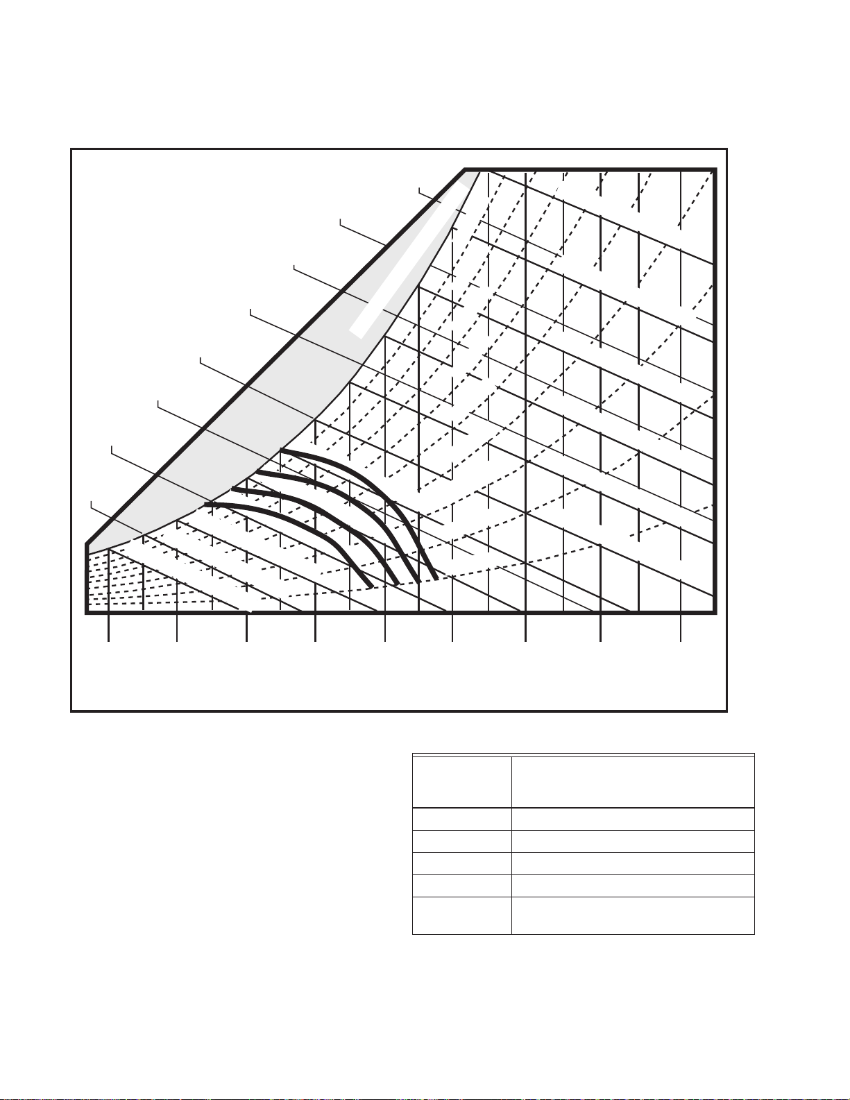
Section 4 - H705 Economizer Module
40 F
4 C
50 F
10 C
60 F
16 C
70 F
21 C
80 F
27 C
90 F
32 C
100 F
38 C
110 F
43 C
120 F
49 C
35 F
2 C
45 F
7 C
55 F
13 C
65 F
18 C
75 F
24 C
85 F
29 C
95 F
35 C
105 F
41 C
115 F
46 C
F 0 9
) C 2 3 (
B L U B T E W
F 5 8
) C 9 2 (
B L U B T E W
F 0 8
) C 7 2 (
B L U B T E W
F 5 7
) C 4 2 (
B L U B T E W
F 0 6
) C 6 1 (
B L U B T E W
F 5 5
) C 3 1 (
B L U B T E W
F 0 5
) C 0 1 (
B L U B T E W
5 4
F
(
7
) C
B L U B T E W
0 4
F
(
4
) C
B L U B T E W
5 3
F
(
2
) C
B L U B T E W
H R % 0 8
H R % 0 7
H R % 0 3
H R % 0 4
H R % 0 5
H R % 0 6
H R % 0 9
H R % 0 1
H R % 0 2
H R % 0 0 1 - N O I T A R U T A S
F 0 7
) C 1 2 (
B L U B T E W
F 5 6
) C 8 1 (
B L U B T E W
DRY BULB TEMPERATURES
15
BTU/LB
34.8 kJ/kg
20 BTU/LB
46.4 k-J/kg
25 BTU/LB
58 k-J/kg
30 BTU/LB
69.7 k-J/kg
35 BTU/LB
81.4 k-J/kg
40 BTU/LB
92.8 k-J/kg
45 BTU/LB
104.5 k-J/kg
50 BTU/LB
116 k-J/kg
A
B
C
D
M25282
H705 Enthalpy Setpoint
This psychrometric chart shows effects of the
various analog economizer logic setpoints
listed. This only applied to single enthalpy
controllers not differential enthalpy. Air with
conditions to the left of the curve is brought in
from outdoors to be used for cooling. When
the outdoor air conditions are to the right of the
curve, the dampers will be set at minimum
position for ventilation and the mechanical
cooling energized. For differential enthalpy the
setpoint knob or potentiometer was turned to
the D setting and the lower of return or outside
air brought into the building.
63-8594-02 Honeywell Economizers 44
Control
Curve
Control Point
(Approximate Temperature
at 50% Humidity)
A 73°F (23°C)
B 70°F (21°C)
C 67°F (19°C)
D 63°F (17°C)
Knob turned
to D
For Differential Enthalpy (2 Sensor)
Example: With A, B, C, D potentiometer logic
module set at “C”. Dry bulb temperature at
65°F (18.3°C) and Relative Humidity (RH) at
50% RH the logic module would free cool on
first call for cooling for commercial thermostat.
Page 51

L1
M13818A
(HOT)
L2
TRANSFORMER
H705 Wiring Diagram
MIXED AIR
DAMPER MOTOR
T1
T2
Section 4 - H705 Economizer Module
H705 ENTHALPY CONTROL
TR1TR
B
C
S
O
A
D
S
R
3
2
1
COOLING
COMMERCIAL THERMOSTAT
ENTHALPY
DECREASE
RC
B
W
120
F
110
100
90
80
R
70
60
B
T991 MIXED
AIR CONTROL
130
140
15
16
170
180
TR
TR1
SR
W R
W
100
80
60
40
+
620 OHM
RESISTOR
1
MINIMUM
POSITION
CONTROL
R
120
140
°F
2
3
C
NC
NO
RELAY
C
Y1
NC
NO
Y2
T1
L1
COOLING
CONTACTOR
T2
L2
The H705 enthalpy control is being used in
this application in place of a dry bulb
temperature economizer high limit. The H705
included a single enthalpy sensor for the
outside air. An optional second C7400
installed in the return air was used for
differential enthalpy. If the second C7400
sensor is not used a 620 ohm resistor was
installed across the SR and + terminals. The
economizer modulated the outdoor dampers
for free cooling provided the outside air
enthalpy was below the setpoint on the H705.
If the outdoor enthalpy is above the setpoint
the outside air dampers are closed to a
minimum position for ventilation and the
mechanical cooling is energized.
45 Honeywell Economizers 63-8594-02
Page 52

Section 4 - H705 Economizer Module
L1
(HOT)
L2
61
4
2
2
2
YELLOW
BLUE
YELLOW
VIOLET
BROWN
VIOLET
BLACK/BLUE
BLACK/RED
WHITE/RED
BLACK/YELLOW
RED
3 3 3
2ND STAGE
COOLING
CONTACTOR
1ST STAGE
COOLING
CONTACTOR
COOLING
TRANSFORMER
3
Y1
B1
W1
R1
Y G C R
Y2
RC
TR1
TR
SR
2
1
3
S
5
PROVIDE DISCONNECT MEANS AND OVERLOAD
PROTECTION AS REQUIRED.
FIELD CONTROL WIRING REQUIRED TO INTEGRATE
ECONOMIZER INTO UNIT.
FIELD WIRING REQUIRED TO PROVIDE ECONOMIZER AND
MECHANICAL COOLING OPERATION IN EXISTING INSTALLATION.
ROOFTOP TERMINAL STRIP IS PART OF AIR CONDITIONING UNIT.
FACTORY-INSTALLED 620 OHM, 1 WATT, 5% RESISTOR SHOULD BE
REMOVED ONLY IF A C7400A SENSOR IS ADDED TO SR AND + FOR
DIFFERENTIAL ENTHALPY.
ENSURE THAT EQUIPMENT TRANSFORMER IS SIZED TO HANDLE
THE EXTRA LOAD OF THE ECONOMIZER AND ACTUATOR.
4
5
6
OPTIONAL
C7400A
W859D ECONOMIZER
CONTROL PACKAGE
1
2
3
620
OHMS
M12162A
MODUTROL®
MOTOR
H705A
T872 SPACE
THERMOSTAT
(COOLING
CIRCUIT)
L1
(HOT)
L2
1
M745
ECONOMIZER
MOTOR
3
L1
(HOT)
L2
1
PROVIDE DISCONNECT MEANS AND OVERLOAD PROTECTION AS
1
REQUIRED.
FACTORY INSTALLED 620 OHM, 1 WATT, 5% RESISTOR SHOULD BE
2
REMOVED ONLY IF A C7400A SENSOR IS ADDED TO SR AND + FOR
DIFFERENTIAL ENTHALPY.
TR
TR
TR
TR
1
RW
2
3
WR B
4
S963A OR Q209
MINIMUM POSITION
POTENTIOMETER
W936 OR W945
ELECTRONIC PANEL
E1
T1
COMMERCIAL
THERMOSTAT
H705A used in electronic system
OPTIONAL
MORNING
WARMUP
E3
E2
H705A
TR
SR
2
ENSURE THAT EQUIPMENT TRANSFORMER IS SIZED TO HANDLE
3
THE EXTRA LOAD OF THE ECONOMIZER AND ACTUATOR.
2
620
OHMS
TR1
3
1
OPTIONAL
C7400A
S
M15037C
63-8594-02 Honeywell Economizers 46
H705A used in electromechanical system
Page 53

T7300
THERMOSTAT
T7300
SUBBASE
RH
RC
Section 4 - H705 Economizer Module
EXISTING HVAC EQUIPMENT
L1
OPTIONAL
C7400A
6
H705A
620
OHMS
TR1
3
1
TR
SR
S
2
2
HVAC
EQUIPMENT
TERMINAL
STRIP
R
SYSTEM
TRANSFORMER
L2
(HOT)
9
X
C2
Y2
C1
H1
FAN
AUX
POWER SUPPLY. PROVIDE DISCONNECT MEANS AND
1
OVERLOAD PROTECTION AS REQUIRED.
FACTORY-INSTALLED 620 OHM, 1 WATT, 5% RESISTOR
2
SHOULD BE REMOVED ONLY IF A C7400A SENSOR IS
ADDED TO SR AND + FOR DIFFERENTIAL ENTHALPY.
3
ENTHALPY CONTROL MAKES TERMINALS 2-1 ON
ENTHALPY RISE, AND 2-3 ON ENTHALPY FALL.
4
RELAY REQUIRED (R8222 OR SIMILAR).
Y1
H2
W2
W1
G
COM
8
LED 1
LED 2
MODUTROL®
MOTOR
A1
A2
B1
W1
R1
T2
T1
4
3
TYPICAL W859D ECONOMIZER CONTROL PACKAGE
MIXED AIR
TEMPERATURE
CONTROLLER
BLUE
4K1
WR B
RISE
MINIMUM POSITION
POTENTIOMETER
YELLOW
WR B
1
L2
L1
(HOT)
3K
BLACK
7
YELLOW
OPEN
4K1
ECONIMIZER MOTOR SPRING RETURNS CLOSED ANY TIME
5
FAN IS NOT RUNNING.
6
FIELD INSTALLED JUMPER.
7
IMPORTANT: MIXED AIR SENSOR MUST BE LOCATED
DOWNSTREAM OF THE EVAPORATOR COIL IN THE DISCHARGE
AIR DUCT TO PROVIDE ECONOMIZER LOW LIMIT FUNCTION.
8
24 VAC ONLY.
9
MUST BE ABLE TO CARRY ADDITIONAL 6 VA LOAD OF
COMMERCIAL THERMOSTAT AND SUBBASE.
4
OUTDOOR AIR
CHANGEOVER
SWITCH
BROWN
1K1
RED
1K2
W1
W2
Y1
Y2
HEAT 1
HEAT 2
5
BLACK/
YELLOW
T675 LOW
AMBIENT
COMPRESSOR
LOCKOUT
VIOLET
VIOLET
FAN
COOL1
COOL 2
W
R
B
M12167B
G
4
BLACK/RED
2K1
2K2
2K
1K
T7300/Q7300 using W859D Economizer Package with H705A in two-stage
heating/two-stage cooling system, defeating economizer minimum position
during unoccupied periods
47 Honeywell Economizers 63-8594-02
Page 54

Section 4 - H705 Economizer Module
63-8594-02 Honeywell Economizers 48
Page 55

Section 5 - M74XX Black Motor
Section 5 - M7XXX Black Motor
49 Honeywell Economizers 63-8594-02
Page 56

Section 5 - M74XX Black Motor
M23890
M13856A
M23891
M7215, M7415, M7405 and M8405 Actuators
rooftop air handlers since the operating
temperature rating is -25 to 125°F
(-32 to 52°C).
TR
24 VAC
TR1
M7215 modulating motor,
with 2-10 Vdc input required.
M7415
W7459A
TR
TR1
T
T1
P1
P
MIN
T
T1
P1
P
SENSOR
POS
M7215 modulating motor. Used with
W7212, W7213, W7214 or W7220 only
TR
24 VAC
SENSOR
MIN
POSN
TR1
T
T1
P1
P
The M7XXX line of spring return actuators are:
• Low torque 25 lb-in. (2.8 N-m)
• 90 second timing in 90 degrees travel
• Rotation of 90 degrees
• Quick connect terminals for wiring
connections
There are more actuators available in this
series than listed on this page. Only actuators
shown on this page are used with the W7459,
W7210, W7212, W7215, W7220 and W7340
economizer modules. They are widely used to
modulate the mixed air dampers on smaller
63-8594-02 Honeywell Economizers 50
M7415 modulating motor, sensor
input or controller required.
Used with W7459A or D only.
NOTE: Using a black motor with a sensor for
economizer changeover is no longer
an acceptable method of economizer
control in ASHRAE 90.1, IECC, ICC
and CA Title 24. Systems with this
type of changeover should be updated
Page 57

to an economizer control strategy
TR
TR1
M3
M1
P1
P
24 VAC
W7401
MIN
POS
M2
M23892
M23893
MAX
MIN
SW
SET
T
X
D
approved by the local or state
authority having jurisdition.
M7405 modulating motor. Used with
W7459B and W7400/T7400 only.
Section 5 - M74XX Black Motor
M8405 3-position actuator.
Used with W7459C only.
51 Honeywell Economizers 63-8594-02
Page 58

Section 5 - M74XX Black Motor
63-8594-02 Honeywell Economizers 52
Page 59

Section 6 - W7459 Economizer Module
Section 6 - W7459 Economizer Module
FOR USE WITH M7415 SERIES ACTUATORS
53 Honeywell Economizers 63-8594-02
Page 60

Section 6 - W7459 Economizer Module
W7459
ENTHALPY
CONTROL
MODULE
M7415, M7405
TERMINALS
W7459 Enthalpy Module Components
W7459 ENTHALPY CONTROL
DAMPER
EXHAUST
AIR
OUTSIDE
AIR SENSOR
+
S
DAMPER
+
RETURN AIR
S
SENSOR
RETURN AIR
FROM ROOM
SUPPLY
AIR TO
BUILDING
DAMPER
LINKAGE
TR
TR1
B C
S
+
O
A
D
S
R
+
5
2
1
4
3
MINIMUM
POSITION
T1
T
OPEN
P1
P
M7415 DAMPER ACTUATOR
WITH W7459 ENTHALPY
CONTROLLER
The W7459 is used in conjunction with a
Honeywell actuator (M7415) and sensors to
control outdoor and return air dampers free
cooling using outside air. It is designed to be
installed directly on the actuator.
OR M8405
ACTUATOR
TR
TR1
COILS
MIXED AIR
SENSOR
FAN
TB8220
COMMERCIAL
PRO
M23907
The W7459 was used with Honeywell C7400A
enthalpy, C7650 or C7660 dry bulb
temperature sensors and the M7415, M7405,
and M8405 actuators. It had to be installed in
free flowing air yet out of direct rain or sunlight.
It can be used as a single or differential
enthalpy control. A minimum position
potentiometer is built into all W7459 modules
except for the W7459C since the M8405
actuator, that it is used with, has the setting
built-in. All W7459 modules can be used with
remote minimum position potentiometers. See
Table 1 for model capability with motors.
T
T1
P1
P
MOTOR
M13837A
63-8594-02 Honeywell Economizers 54
Page 61

Table 1. Economizer Usage
Section 6 - W7459 Economizer Module
For use
Model
with
Actuator
Discharge Air
Temperature Input
W7459A M7415 C7510B or C7046A
Minimum Position
Potentiometer
Yes Yes 2 SPDT
Terminals for
Remote Minimum
Damper Position
Sensor
W7459B M7405A Direct digital control
Yes Yes 1 SPDT
W7401/W7411 Logic
Panel
W7459C M8405 SPST control No. Minimum position
No 2 SPDT
adjustment is built into
M8405 Actuator.
W7459D
M7415 C7150B or C7046A
Yes Yes 2 SPDT
a
Sensor
a
W7459D has a high enthalpy limit and defaults to mechanical cooling when the outdoor enthalpy reaches the preset limit.
Do not use a dry bulb sensor for a high temperature limit.
Output
Relays
55 Honeywell Economizers 63-8594-02
Page 62

Section 6 - W7459 Economizer Module
ENTHALPY
CHANGEOVER
SETPOINT DIAL
LIGHT IS
ILLUMINATED IF
OUTDOOR AIR
IS USEABLE FOR
FREE COOLING
NOTE: USE SMALL SCREWDRIVERS ON THE POTENTIOMETERS.
DO NOT USE EXCESSIVE FORCE!
MININUM
POSITION DIAL
(W7459A AND D
ONLY)
POSITION POTENTIOMETER
M23896A
MIXED AIR CONTROL
NOTE: USE SMALL SCREWDRIVERS ON THE POTENTIOMETERS.
DO NOT USE EXCESSIVE FORCE!
W7459A, B, C and D
TR1
+
+
5
2
4
T1
P1
TRANSFORMER
(POWER) TERMINALS
OUTSIDE AIR
SENSOR TERMINALS
RETURN AIR
SENSOR TERMINALS
COOLING SWITCHING
CONTROLLED FROM
COOLING STAT
MIXED OR SUPPLY
AIR SENSOR
REMOTE MINIMUM
M23894A
BC
A
MINIMUM
POSITION
OPEN
TR
S
O
D
S
R
1
3
T
P
W7459A
W7459A or D - Uses inputs from mixed or
discharge air temperature sensors, C7150 or
C7046; enthalpy sensor C7400; and optional
remote minimum position potentiometer
Q709A or S963B. The W7459D is identical to
the W7459A except for the addition of a builtin enthalpy high limit. Refer to high limit
function in Table 2 and at the end of this
section. Use both modules with M7415
motors.
There are four separate W7459 enthalpy logic
modules for use with various M74XX series
actuators. All provide enthalpy control of
mixed air. The W7459B is designed for use
with a legacy Honeywell direct digital
controller. The W7459C uses a SPST input for
the mixed air sensor.
TR1
TR
BC
S
A
D
S
M3
MINIMUM
POSITION
M2
OPEN
NOTE: USE SMALL SCREWDRIVERS ON THE POTENTIOMETERS.
DO NOT USE EXCESSIVE FORCE!
+
O
R
+
3
1
2
M1
P1
P
M23895A
W7459B
W7459B - Used with Honeywell W7401 Logic
Panel, enthalpy sensor C7400 or minimum
position potentiometer Q709A or S963B. Use
with M7405.
TR
TR1
BC
S
A
D
S
+
O
R
+
5
2
1
X TERMINAL IS USED
4
3
X
D
6
WITH A ST6008 TIMER
FOR OCCUPIED/
UNOCCUPIED
(T675/T6031)
CONNECTED TO
TERMINALS 6 AND D
63-8594-02 Honeywell Economizers 56
W7459C
W7459C - Uses input from SPST mixed or
discharge air control and enthalpy sensor
C7400. Used with M8405.
Page 63

Section 6 - W7459 Economizer Module
40 °F
4 °C
50 °F
10 °C
60 °F
16 °C
70 °F
21 °C
80 °F
27 °C
90 °F
32 °C
100 °F
38 °C
110 F
43 °C
120 °F
49 °C
35 °F
2 °C
45 °F
7 °C
55 °F
13 °C
65 °F
18 °C
75 °F
24 °C
85 °F
29 °C
95 °F
35 °C
105 °F
41 °C
115 °F
46 °C
°F
09
)
°C
23(
BLUB TEW
°F
58
)
°C
92(
BLUB TEW
°F
08
)
°C
72(
BLUB TEW
°F
57
)
°C
42(
BLUB TEW
°F
06
)
°C
61(
BLUB TEW
54
°F
(
7
)
°C
BLUB TEW
04
°F
(
4
)
°C
BLUB TEW
53
°F
(
2
)
°C
BLUB TEW
HR %08
HR %07
HR %03
HR %04
HR %05
HR %06
HR %09
HR %01
HR %02
HR %001-NOITARUTAS
°F
07
)
°C
12(
BLUB TEW
°F
56
)
°C
81(
BLUB TEW
DRY BULB TEMPERATURES
15
BTU/LB
34.8 kJ/kg
20 BTU/LB
46.4 k-J/kg
25 BTU/LB
58 k-J/kg
30 BTU/LB
69.7 k-J/kg
35 BTU/LB
81.4 k-J/kg
40 BTU/LB
92.8 k-J/kg
45 BTU/LB
104.5 k-J/kg
50 BTU/LB
116 k-J/kg
A
B
C
D
HIGH LIMIT
CURVE FOR
W7459 D,
W6210D AND
W7210D
M25283A
°F
55
)
°C
31(
BLUB TEW
°F
05
)
°C
01(
BLUB TEW
W7459 Enthalpy Setpoint Chart
This is the psychrometric chart for the setpoint
on the W7459 enthalpy modules. It is similar
to the charts for the H705 except for the
enthalpy high limit line to the right of the A
curve. This is a specialized limit used only in
the W7459D, W6210D, W7210D and W7212
controllers. When the enthalpy of both the
return and outside air is to the right of the limit
line the outside air dampers are closed to the
minimum position and the mechanical cooling
is energized.
Control Curve
A 73°F (23°C)
B 70°F (21°C)
C 67°F (19°C)
D 63°F (17°C)
Knob turned
to D
Control Point
(Approximate Temperature
at 50% Humidity)
For Differential Enthalpy
(2 Sensor)
When using differential enthalpy the outdoor
air is compared to the return air and you set
57 Honeywell Economizers 63-8594-02
the potentiometer to "D" to prevent the return
air from being to the left of the enthalpy curve.
Page 64

Section 6 - W7459 Economizer Module
If the return air were to the left of the enthalpy
curve, you would use the enthalpy curve
instead of the return air conditions. For
example, if the return air conditions were
between D and C and the outdoor was to the
right of the A AND the potentiometer was set
to B, you would use the B curve instead of the
return air. If the outdoor air conditions were to
the left of the return air you would use the
outdoor air. If the outdoor conditions are to the
right of the return air conditions you use the
return air.
High Limit Switching
Table 2. W7459D, W7210D and W7212 High Limit Switching.
Switch Over Point on Enthalpy
Percent RH
25 83°F ±0.5°F (28°C ±0.3°C) 85°F ±0.5°F (29°C ±0.3°C)
50 78°F ±0.5°F (26°C ±0.3°C) 80°F ±0.5°F (27°C ±0.3°C)
60 76°F ±0.5°F (24°C ±0.3°C) 78°F ±0.5°F (26°C ±0.3°C)
75 73°F ±0.5°F (23°C ±0.3°C) 75°F ±0.5°F (24°C ±0.3°C)
The W7459D, W6210D, W7210D, and W7212
include the high limit function that is not used
on any other economizer modules. It is a high
enthalpy limit that applies to both return and
outside air. It only applies when using
differential changeover, not single enthalpy.
When the return and outside enthalpy both
exceed the high limit curve, (refer to the
psychrometric chart on the previous page) the
outside air dampers are closed to the
minimum position and the mechanical cooling
is energized. In a standard differential
enthalpy control sequence the lower of the
outside and return is selected regardless of
the amount of enthalpy in either.
Decreasing
A typical application of this limit function is a
building located in a warm, humid climate with
a high internal heat gain such as a laundry or
kitchen. A standard differential enthalpy
control circuit may have extremely warm,
humid outside air being cooled just because
the indoor air is temporarily higher in enthalpy.
The mechanical cooling equipment might be
undersized and the indoor enthalpy then
remains higher than outside longer than the
desired period of time. The high limit function
(only available on some economizer modules)
prevents this from occurring by automatically
switching to return air and turning on the
mechanical cooling during very high outdoor
air enthalpy conditions.
Switch Over Point on Enthalpy
Increasing
63-8594-02 Honeywell Economizers 58
Page 65

Section 6 - W7459 Economizer Module
M13819A
THEY NEED CONSTANT POWER.
W7459A Wiring Diagram
C7400 OURDOOR AIR
ENTHALPY SENSOR
+
S
+
S
C7400 RETURN AIR
ENTHALPY SENSOR
C7150 OR C7046
MIXED OR SUPPLY
AIR SENSOR
Y1
Y2
W2
W1
W7459A ECONOMIZER MODULE
RELAYS 1K AND 2K ENERGIZE
IF OUTDOOR ENTHALPY
EXCEEDS RETURN AIR ENTHALPY
1S
1S SWITCHES
WHEN
POWERED BY
24 VOLTS
1K
1S1
MINIMUM POSITION
ADJUSTMENT
LOW O.A. AMBIENT
COMPRESSOR
LOCKOUT STAT
(OPTIONAL)
120
F
R W
110
130
100
140
90
15
80
16
70
170
60
180
TR TR1
S
O
+
S
R
+
5
2
1
3
42K
T1
T
P1
P
M7415 ACTUATOR
TR
1
24 VAC
TR1
T
MIXED AIR
SENSOR
T1
P1
MINIMUM
POSITION
P
HVAC EQUIPMENT TERMINAL STRIP
TRANSFORMER
1
C
Y1
Y2
W2
W1
COOL1
COOL2
HEAT 2
HEAT 1
G
RH
RC
COMMERCIAL
THERMOSTAT
HONEYWELL RECOMMENDS USE OF A SINGLE LARGE TRANSFORMER FOR BOTH THE ECONOMIZER LOGIC MODULE
1
AND THE COOLING COMMERCIAL THERMOSTAT CIRCUIT.
2
WHEN THE SUPPLY FAN IS POWERED, THE ECONOMIZER IS POWERED AND THE DAMPER IS POSITIONED TO
MINIMUM POSITION. TAKE CAUTION WHEN USING THIS CONTROL SEQUENCE ON NEWER ECONOMIZERS WITH
MICROPROCESSOR CONTROL. DO NOT POWER THE MICROPROCESSOR ECONOMIZERS FROM THE SUPPLY FAN,
FAN DELAY
G
FDR
FAN
R
59 Honeywell Economizers 63-8594-02
Page 66
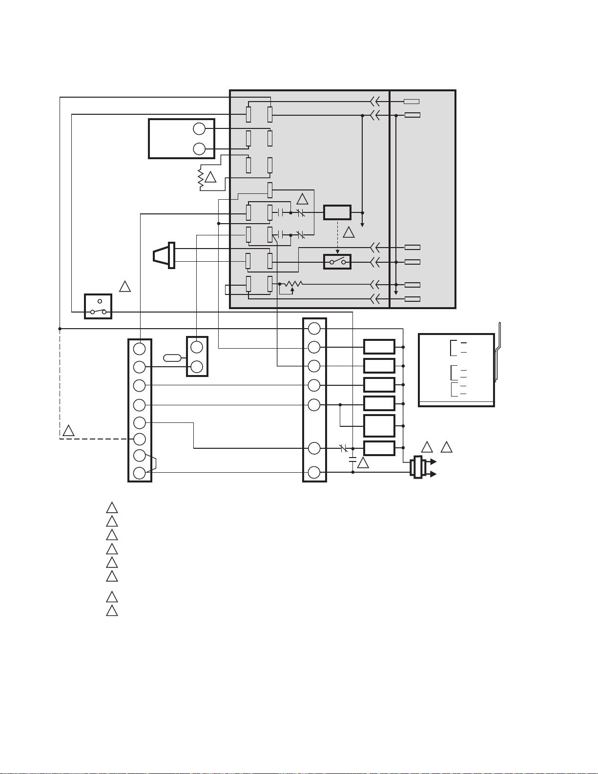
Section 6 - W7459 Economizer Module
C7400
OUTDOOR
AIR
ENTHALPY
SENSOR
620 OHM
RESISTOR
C7150B MIXED
AIR OR
UNOCCUPIED
OCCUPIED
7
8
C7046A
ST6008
TIMER
DISCHARGE
AIR SENSOR
Y1
Y2
W2
W1
G
X
RH
RC
T7300 OR T874
THERMOSTAT
1
POWER SUPPLY. PROVIDE DISCONNECT MEANS AND OVERLOAD PROTECTION AS REQUIRED.
2
MOTOR SPRING-RETURNS CLOSED WHEN FAN IS NOT RUNNING.
3
ENSURE THAT EQUIPMENT TRANSFORMER IS SIZED TO HANDLE THE EXTRA LOAD OF THE ECONOMIZER AND ACTUATOR.
1S IS AN ELECTRONIC SWITCH THAT CLOSES WHEN POWERED BY A 24 VAC INPUT.
4
5
RELAYS 1K AND 2K ACTUATE WHEN THE ENTHALPY SENSED BY THE C7400 IS HIGHER THAN THE ENTHALPY SETPOINT A-D.
6
FACTORY INSTALLED 620 OHM, 1 WATT, 5% RESISTOR SHOULD BE REMOVED ONLY IF A C7400 ENTHALPY SENSOR
IS ADDED TO SR AND + FOR DIFFERENTIAL ENTHALPY.
FOR T7300 ONLY.
7
WITH T7300, USE CONTACTS A1 AND A2 INSTEAD OF S7005 TIMER.
8
+
S
6
W
T6031 AMBIENT
LOCKOUT
R
CONTROL
50 F SETPOINT
TR TR1
S
O
S
R
1
3
T
P
+
+
5
2
4
T1
P1
1K
5
1S
2K
1S1
MINIMUM POSITION
ADJUSTMENT
C
Y1
Y2
W2
W1
FDR
G
FDR
R
HVAC EQUIPMENT
TERMINAL STRIP
M7415 ACTUATORW7459A ECONOMIZER PACKAGE
TR
24 VAC
TR1
4
COOL 1
COOL 2
HEAT 2
HEAT 1
FAN
DELAY
RELAY
FAN
2
T
T1
P1
P
MIXED
AIR
SENSOR
MINIMUM
POSITION
24 VAC
SENSOR
MIN
POS
1
L2
L1
(HOT)
M7415
3
TR
TR1
T1
T
P1
P
M10115C
W7459A/C7400 used in two-stage cooling system with
single enthalpy changeover and with M7415 Actuator
63-8594-02 Honeywell Economizers 60
Page 67

8
UNOCCUPIED
ST6008
TIMER
C7400
OUTDOOR
AIR
ENTHALPY
SENSOR
620 OHM
RESISTOR
C7150B MIXED
AIR OR
C7046A
DISCHARGE
AIR SENSOR
Section 6 - W7459 Economizer Module
M7415 ACTUATORW7459A ECONOMIZER PACKAGE
TR
24 VAC
TR TR1
+
+
S
S
6
O
S
+
R
5
1K
1
2
4
3
T
T1
P
P1
5
2K
MINIMUM POSITION
ADJUSTMENT
1S
4
1S1
TR1
T
T1
P1
P
MIXED
AIR
SENSOR
MINIMUM
POSITION
OCCUPIED
W
T775 CONTROLLER
7
C
+
NC
C
NO
NO
C
NC
1
POWER SUPPLY. PROVIDE DISCONNECT MEANS AND OVERLOAD PROTECTION AS REQUIRED.
2
MOTOR SPRING-RETURNS CLOSED WHEN FAN IS NOT RUNNING.
3
ENSURE THAT EQUIPMENT TRANSFORMER IS SIZED TO HANDLE THE EXTRA LOAD OF THE ECONOMIZER AND ACTUATOR.
1S IS AN ELECTRONIC SWITCH, WHICH CLOSES WHEN POWERED BY A 24 VAC INPUT.
4
5
RELAYS 1K AND 2K ACTUATE WHEN THE ENTHALPY SENSED BY THE C7400 IS HIGHER THAN THE ENTHALPY SETPOINT A-D.
FACTORY INSTALLED 620 OHM, 1 WATT, 5% RESISTOR SHOULD BE REMOVED ONLY IF A C7400 ENTHALPY SENSOR
6
IS ADDED TO SR AND + FOR DIFFERENTIAL ENTHALPY.
7
T775 REQUIRES A MINIMUM OF THREE RELAY OUTPUTS: TWO FOR COOLING AND ONE FOR FAN CONTROL.
8
T775 SERIES 2000 CAN BE PROGRAMMED TO PROVIDE TIME OF DAY CLOCK AND THE ST6008 TIMER CAN BE ELIMINATED.
NC
C
NO
NO
C
NC
T6031 AMBIENT
LOCKOUT
R
CONTROL
50 F SETPOINT
C
Y1
Y2
G
R
HVAC EQUIPMENT
TERMINAL STRIP
COOL 1
COOL 2
2
FAN
24 VAC
SENSOR
MIN
POS
M7415
3
TR
TR1
T1
T
P1
P
L2
1
L1
(HOT)
M13843B
W7459A/C7400 or W7459D/C7400 used in two-stage cooling system with
single enthalpy changeover, M7415 Actuator, and T775 Series 2000 Controller
61 Honeywell Economizers 63-8594-02
Page 68

Section 6 - W7459 Economizer Module
63-8594-02 Honeywell Economizers 62
Page 69

Section 7 - W6210 And W7210 Economizer Modules
Section 7 - W6210 And W7210
Economizer Modules
63 Honeywell Economizers 63-8594-02
Page 70

Section 7 - W6210 And W7210 Economizer Modules
W7210 Economizer System Components
DAMPER
EXHAUST
AIR
OUTSIDE
AIR SENSOR
+
S
RETURN
+
S
AIR SENSOR
COILS
FAN
DISHCHARGE
AIR SENSOR
RETURN AIR
FROM ROOM
SUPPLY
AIR TO
BUILDING
T7350
PROGRAMMABLE
THERMOSTAT
24 VAC
HOT
24 VAC
COM
W7210 A 1001
+
2-10V
OUT
–
W7210 SOLID
STATE
ECONOMIZER
LOGIC MODULE
M23902A
63-8594-02 Honeywell Economizers 64
Page 71

Section 7 - W6210 And W7210 Economizer Modules
2-10V
OUT
24 VAC
HOT
24 VAC
COM
1
TR
COM1
+
+
BADC
TR
HOT
24 VAC
SO
SR
5
2
4
T1
P1
T
P
MINIMUM
POSITION
OPEN
FREE
COOLING
W7210 A 1001
SINGLE ENTHALPY
SETPOINT
MINIMUM DAMPER POSITION
SETPOINT
FREE COOLING MODE LIGHT
M23897A
+
–
24 VAC POWER TERMINALS
OUTSIDE AIR ENTALPY SENSOR
ACTUATOR
POWER SUPPLY
TERMINALS
ACTUATOR
TERMINALS
RETURN AIR ENTHALPY SENSOR
COOLING SWITCHING
CONTROLLED FROM
COOLING STAT
3
REMOTE MINIMUM
POSITION POTENTIOMETER
MIXED AIR SENSOR
W6210 and W7210 Components
The W7210 logic modules had the identical
functions as the W7459 modules with the
addition of a 2-10 Vdc output for use with
M7215 foot-mounted actuators or DCA’s and
Modutrol Motors with 2-10 Vdc control. The
mixed air control circuit was in the logic
module and no longer in the actuator. The
actuator could also be powered with the same
24 Vac power as the logic modules provided
the internal grounding of the actuator was
compatible. Note some of the non-Honeywell
actuators were not compatible with the
M7210.
High Limit Function
There were high limit versions of these
economizer logic modules, W7210D. When in
the differential enthalpy mode and both the
return and outside air enthalpy were above a
preset level, the outside air dampers were
returned to minimum position and the
mechanical cooling was energized. The curve
for this limit function is illustrated on the
psychrometric chart as the line to the right of
the A curve. Refer to high limit section of this
guide for more information.
Wiring Connections
There are many possible wiring diagrams and
combinations of controllers and actuators that
can be used with the logic modules. Once you
understand the input and output of the
modules, you can usually determine how a
system should be wired.
NOTE: Many user systems are wired to
bypass operations and to “trick” the
module into operating in a mode that it
was not designed to do, these are the
applications which may confuse you.
When is doubt, call the unit supplier or
refer to the product instructions for
wiring diagrams.
65 Honeywell Economizers 63-8594-02
Page 72

Section 7 - W6210 And W7210 Economizer Modules
24 VAC
HOT
24 VAC
COM
+
2-10V
OUT
_
500
500
0
30
60
90
60
30
SINGLE MS7503 or MS7505
ACTUATOR
W7210 OR W7215
ECONOMIZER
MODULE
RED
BLACK
WHITE
PARALLEL MS7503 or MS7505 ACTUATORS
24 VAC
HOT
24 VAC
COM
+
2-10V
OUT
_
500
500
0
30
60
90
60
30
W7210 OR W7215
ECONOMIZER
MODULE
RED
BLACK
WHITE
500
500
0
30
60
90
60
30
WHITE
RED
BLACK
M13824A
W7210 Actuator Connections
63-8594-02 Honeywell Economizers 66
Page 73

L1
(HOT)
L2
FDR
FDR
FAN
FAN
DELAY
RELAY
HEAT 1
HEAT 2
COOL 1
HVAC EQUIPMENT
TERMINAL STRIP
POWER SUPPLY. PROVIDE DISCONNECT MEANS AND OVERLOAD PROTECTION AS REQUIRED.
ACTUATOR SPRING-RETURNS CLOSED WHEN FAN IS NOT RUNNING.
ENSURE THAT EQUIPMENT TRANSFORMER IS SIZED TO HANDLE THE EXTRA LOAD OF THE ECONOMIZER AND ACTUATOR.
1S IS AN ELECTRONIC SWITCH THAT CLOSES WHEN POWERED BY A 24 VAC INPUT.
RELAYS 1K AND 2K ACTUATE WHEN THE ENTHALPY SENSED BY THE C7400 IS HIGHER THAN THE ENTHALPY SETPOINT A-D.
FACTORY INSTALLED 620 OHM, 1 WATT, 5% RESISTOR SHOULD BE REMOVED ONLY WHEN A C7400 ENTHALPY SENSOR
IS ADDED TO SR AND + FOR DIFFERENTIAL ENTHALPY.
FOR T7300 ONLY.
FOR T7300, USE CONTACTS A1 AND A2 INSTEAD OF THE TIMER.
FOR THE ML7295A,C USE THE 4-20 MA MODEL ACTUATOR. THESE MODELS HAVE 500 OHM INPUT IMPEDENCE,
WHICH ALLOWS THE ACTUATOR TO ACCEPT A 2-10 VDC SIGNAL.
M111 54B
T7300 OR T874
THERMOSTAT
P1
P
T1
1
3
4
2
5
2K
S
1
1
2
3
4
6
8
7
TR TR1
S
O
S
R
+
+
W7210A,D
+
C
G
W1
Y1
R
W2
RC
G
X
W1
Y1
Y2
W2
C7400
OUTDOOR
AIR
ENTHALPY
SENSOR
UNOCCUPIED
OCCUPIED
ST6008
TIMER
3
2
5
1K
COOL 2
Y2
4
5
T
6
7
8
1S
1S1
C7150B MIXED
AIR OR
C7046A
DISCHARGE
AIR SENSOR
620 OHM
RESISTOR
W
R
T6031 AMBIENT
LOCKOUT
CONTROL
50 F SETPOINT
RH
MINIMUM POSITION
ADJUSTMENT
9
9
+
–
2-10V
OUT
24 VAC HOT
24 VAC COM
HONEYWELL
SERIES 72
ACTUATOR
(ML7275,
ML7285,
ML7295A,C
M7275,
M7285)
+
Section 7 - W6210 And W7210 Economizer Modules
W7210 Wiring Diagrams
W7210A,D used in two-stage cooling system with single
enthalpy changeover and Honeywell Series 72 Actuator
67 Honeywell Economizers 63-8594-02
Page 74

Section 7 - W6210 And W7210 Economizer Modules
63-8594-02 Honeywell Economizers 68
Page 75

Section 8 - W6215, W7215 And W7460 Economizer Modules
Section 8- W6215, W7215 And W7460
Economizer Modules
69 Honeywell Economizers 63-8594-02
Page 76

Section 8- W6215, W7215 And W7460 Economizer Modules
W7215 System Components
DAMPER
EXHAUST
AIR
OUTSIDE
AIR SENSOR
+
S
RETURN
+
S
AIR SENSOR
MIXED AIR
SENSOR
COILS
FAN
W7215 ECONOMIZER
LOGIC MODULE
RETURN AIR
FROM ROOM
SUPPLY
AIR TO
BUILDING
T7350
PROGRAMMABLE
THERMOSTAT
C7232 ROOM
CARBON DIOXIDE
SENSOR
+
–
W7215B
M23903A
63-8594-02 Honeywell Economizers 70
Page 77
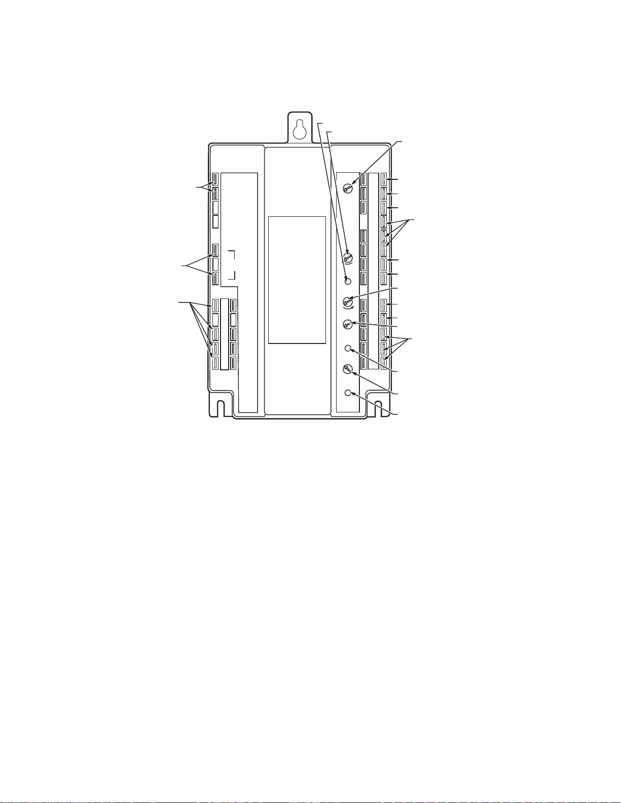
Section 8 - W6215, W7215 And W7460 Economizer Modules
24VAC
TR Hot
24VAC
Com
24VAC
Hot
2-10V
OUT
Free
Cool
Unit
Control
Exhaust
Fan
Indoor
Fan
Mininum
Position
Maximum
Position
Open
Free Cool
Closed
ISI
Exhaust
Exhaust
Set Pt
0%
100%
50%
2V
6V
10V
ISI
Set Pt
A
BC
D
TR1
Com
+
+
5
2
4
1
T1
T
P1
Q1
AQ1
AQ
SD1
SD
AC1
AC
PG1
PG
So
Sr
W7215A
+
–
SINGLE ENTHALPY SETPOINT
MAXIMUM DAMPER POSITION
SETPOINT FOR DCV
DCV SENSOR SETPOINT
EXHAUST FAN ENERGIZED
SETPOINT
Q
M23898A
+
–
ACTUATOR POWER
SUPPLY TERMINALS
ACTUATOR
CONTROL
TERMINALS
CONTACT
OUTPUTS
NOTE: ALL INPUT AND OUTPUT WIRING MUST BE 24 VAC CLASS 2.
TRANSFORMER TERMINALS
OUTSIDE AIR ENTHALPY SENSOR
RETURN AIR ENTHALPY SENSOR
COOLING SWITCHING
CONTROLLED FROM
COOLING STAT TO COMPRESSOR
(TERMINALS 1-5)
MIXED AIR SENSOR
REMOTE MINIMUM POSITION
POTENTIOMETER
REMOTE MAXIMUM DAMPER POSITION
POTENTIOMETER
CONTACT INPUTS TO INITIATE
CONTROL SEQUENCES
Q
DCV MODE LIGHT
CO2 SENSOR INPUT
EXHAUST FAN ENERGIZED LIGHT
MINIMUM DAMPER POSITION SETPOINT
P
FREE COOLING MODE LIGHT
3
W6215, W7215 and W7460 Components
The W7215A is an economizer module for use
with series 72 actuators. The W7215B is
similar except for an outside air content sensor
input and slightly different contact inputs and
The W7215B and W7460B are equipped with
outdoor air content sensor inputs. There are
slight variations to the input and output
terminals:
• The purge function is eliminated.
• An alarm contact output is added for when
the indoor DCV and outdoor air content
setpoints are simultaneously exceeded.
W7215B and W7460B Components
outputs. The W6215A was for use with series
62 actuators but otherwise identical to the
W7215A. The W7460A was for use with the
M7415 actuator.
• The exhaust fan setpoint and exhaust
indication light are eliminated.
• An outdoor air content sensor setpoint and
indication light are added.
71 Honeywell Economizers 63-8594-02
Page 78

Section 8- W6215, W7215 And W7460 Economizer Modules
M13842A
FAN
HEATING COIL
COOLING COIL
NOT TO BE USED AS A LIFE SAFETY DEVICE
SD1
AC1
SD
AC
FREE
COOL
UNIT
CONTROL
EXHAUST
FAN
INDOOR
FAN
OCCUPANCY
TIMER
W7215B
W7460B
ECONOMIZER
MODULES
FREE COOLING
HOUR COUNTER
ALARM
TO AIR CLEANER OR
AIR CONTENT ALARM
ISI
OSI
OSI
Set Pt
2V
100%
6V
2V
6V
10V
ISI
Set Pt
AQ1
AQ
SD1
SD
AC1
AC
0A1
0A
DCV SENSOR
SETPOINT
OUTDOOR AIR
CONTENT SENSOR
SETPOINT
+
–
DCV MODE LIGHT
OUTDOOR AIR
CONTENT
MODE LIGHT
EXHAUST AIR
W6215, W7215, W7460 Inputs and Outputs
This series of economizer modules includes
input and output contacts for use in controlling
the fans and conditioning equipment on the air
Input and Output Applications
FREE
COOLING
HOUR
COUNTER
HEATING COIL
COOLING COIL
EXHAUST AIR
FAN
NOT TO BE USED AS A LIFE SAFETY DEVICE
FREE
COOL
UNIT
CONTROL
EXHAUST
FAN
INDOOR
FAN
W6215A
W7215A
W7460A
ECONOMIZER
MODULES
SD
PG
SD1
AC
AC1
PG1
Options Available on A Models
handler. Some of these contacts are not
available on all modules.
EXHAUST FAN
SETPOINT
OCCUPANCY
TIMER
SMOKE, FIRE
DETECTION
CIRCUIT
Exhaust
Fan
Indoor
Fan
0%
Exhaust
Set Pt
Exhaust
AC
AC1
ISI
PG1
50%
PG
100%
M13841A
63-8594-02 Honeywell Economizers 72
Options Available on B Models
Page 79

M23923A
POSITION CONTROL
POSITION CONTROL
DAMPER POSITION
100% OPEN
M23972A
Minimum and Maximum Settings
Mininum
3
Position
Open
Free Cool
Maximum
Position
Closed
6V
AQ
10V
2V
This series of economizer modules includes
both minimum and maximum damper position
settings. Previous economizer controls are
equipped with only a minimum setting to
maintain a volume of outside air for ventilation.
The minimum setting on these modules is to
ventilate for the building components when
using DCV or to ventilate for cfm per person
for maximum occupancy when not using DCV.
The maximum setting is used to limit the
amount of outside air brought into the air
handler.
4
T1
T
P1
P
Q
Q1
AQ1
AN1
GND
C7150 OR C7046
MIXED OR SUPPLY
AIR SENSOR
100
80
120
REMOTE MINIMUM
60
40
140
°F
100
80
120
REMOTE MINIMUM
60
40
140
°F
C7232 OR C7632
DCV CO
ppm
SENSOR
2
Section 8 - W6215, W7215 And W7460 Economizer Modules
DCV MIN
POSITION
MIN POS
0% OPEN
CODE VENTILATION RATE
450 PPM 800 PPM 2000 PPM
CO2 LEVEL
NORMAL OPERATION WITHOUT DCV
CO2 SENSOR ONLY
DCV ECONOMIZER FULL OCCUPANCY
DCV ECONOMIZER
When using DCV, this is the sum of the
ventilation for the building components and
maximum human occupancy. See above
diagram for control of dampers using DCV and
minimum and maximum damper positions.
When DCV is not used this setting can be
used to limit the amount of outside air brought
into the system.
If the dampers are being modulated as the first
stage of cooling from the commercial
thermostat, the DCV maximum setting is not in
the circuit and the dampers can be opened
fully as needed. If the dampers are being
modulated from both the thermostat and the
DCV sensor, the dampers will be opened to
whichever is a higher signal. If the mixed air
temperature decreases below 40°F (4°C) the
signal from the DCV sensor is ignored and the
dampers are modulated toward closed to
prevent freezing of coils and other equipment
in the air handling unit.
73 Honeywell Economizers 63-8594-02
Page 80

Section 8- W6215, W7215 And W7460 Economizer Modules
24VAC
TR Hot
24VAC
Com
24VAC
Hot
2-10V
OUT
Free
Cool
Unit
Control
Exhaust
Fan
Indoor
Fan
Mininum
Position
Maximum
Position
Open
Free Cooling
Close
ISI
OSI
OSI
Set Pt
2V
100%
6V
2V
6V
10V
ISI
Set Pt
A
BC
D
TR1
Com
+
+
5
2
4
1
T1
T
P1
Q1
AQ1
AQ
SD1
SD
AC1
AC
0A1
0A
So
Sr
W7215B
+
–
M23925A
+
–
Q
P
3
Alarm
C7242 INDOOR
AIR CONTENT
CO2 SENSOR
ECONOMIZER
MODULE WITH
DCV SENSOR INPUT
DCV SENSOR
INPUT ON
TEMINALS
AQ AND AQ1
2V
6V
10V
DCV
Set Pt
ROOM CONCENTRATION CARBON
DIOXIDE IN PARTS PER MILLION
500
650
800
950
1100
1250
1400
1550
1700
1850
2000
SENSOR OUTPUT
IN VOLTS DC
0
1
2
3
4
5
6
7
8
9
10
Indoor Air Content Sensor Settings
The DCV input can be any sensor with a 2 to
10 Vdc output such as the Honeywell C7242,
C7232 or C7632 carbon dioxide (CO2)sensor.
The sensor is supplied with preset
configurations that can be used if they meet
63-8594-02 Honeywell Economizers 74
the application requirements. The output chart
illustrated on the right side of this page is the
Analog 1 configuration of startpoint and
throttling range for a linear output.
Page 81

Section 8 - W6215, W7215 And W7460 Economizer Modules
Carbon Dioxide Sensor Setup
CO2
Sensors Display No Display A1 Output A2 Output
Wall Mount
With Relay
Wall Mount C7242A1014 C7242A1022 Analog Sensor Mode:
Duct Mount C7242B1012 C7242B1020
Outside Air Not Available C7232E1007
C7242A1030 C7242A1048 0 Vdc = 500 ppm
(2 Vdc = 800 ppm) and
10 Vdc = 2,00 ppm
Relay Output:
0 to 800 ppm = Open,
More than 800 ppm = Closed,
Reopens at less than 700 ppm
0 Vdc = 500 ppm
(2 Vdc = 800 ppm) and
10 Vdc = 2,000 ppm
Time interval = 2 seconds
For applications where factory configurations
do not meet the application requirements the
sensor may be re-configured by the installer to
meet most configuration needs.
Most installers prefer to use a C7632 CO2
sensor that does not need to be programed or
adjusted when installed.
75 Honeywell Economizers 63-8594-02
Page 82

Section 8- W6215, W7215 And W7460 Economizer Modules
Outdoor Air Content Sensor
Outdoor Air
Content
Sensor DCV Mixed Air Damper Actuator
Below
Setpoint
Above
Setpoint
The purpose of the DCV sensor is different
from that of the outdoor air content sensor. On
the economizer modules equipped with
outdoor air content sensors the purpose of the
sensor is to keep the outside air dampers at a
Below
Setpoint
Above
Setpoint
Below
Setpoint
Above
Setpoint
Modulation based on signal from mixed air
temperature sensor.
Modulation between minimum and maximum
positions based on signal from either mixed air
or indoor air content sensors, whichever signal
is higher.
Closed fully. On Open
Modulation based on signal from mixed air
temperature sensor. Terminals labeled Alarm
made to energize warning light, audio alarm or
air cleaner.
minimum position if the outdoor air is above its
setpoint threshold. Alarm contacts on the
economizer module will close if both the
outdoor and indoor air (DCV) signals are
above their respective setpoint thresholds.
Outdoor Air
Content Sensor
Light
Off Open
Off Open
On Closed
Alarm
Contacts
63-8594-02 Honeywell Economizers 76
Page 83

Section 8 - W6215, W7215 And W7460 Economizer Modules
24 VAC
HOT
24 VAC
COM
+
2-10V
OUT
_
500
500
0
30
60
90
60
30
MS7503 OR MS7505
ACTUATOR
W7210 OR W7215
ECONOMIZER
MODULE
RED
BLACK
WHITE
M13830A
W6215, W7215 and W7460 Actuator Usage
M7415 ACTUATOR
24 VAC
SENSOR
MIN
POSN
TR
TR1
T
T1
P1
<
P
L2
L1
W7210 OR W7215
ECONOMIZER
MODULE
24 VAC
HOT
24 VAC
COM
1
The W7460 can only be used with the M7415
actuator. The W7215 can be used with series
72 actuators (Direct Coupled Actuators,
+
_
Q769C MINIMUM
POSITION POTENTIOMETER
1
WHEN USING THE W7210 OR W7215 WITH A M7415
+
_
2-10V
OUT
ACTUATOR, THE MIXED OR DISCHARGE AIR SENSOR
MUST BE CONNECTED TO THE LOGIC MODULE AND
NOT THE ACTUATOR.
M13827A
M7215 and Modutrol motors). The W6215 is
only usable with series 62 actuators.
77 Honeywell Economizers 63-8594-02
Page 84

Section 8- W6215, W7215 And W7460 Economizer Modules
W6215, W7215 and W7460 Wiring Diagram
W7215A
HONEYWELL
SERIES 72
ACTUATOR
(ML7275,
ML7285,
ML7295A,C
M7275,
M7285)
+
5
24 VAC HOT
24 VAC COM
1S
4
+
2-10 VDC
OUT
––
1S1
MINIMUM POSITION
ADJUSTMENT
FREE
COOL
UNIT
CONTROL
EXHAUST
FAN
INDOOR
FAN
MAXIMUM
POSITION
ADJUSTMENT
TR1
TR
C7400
+
9
OUTDOOR
AIR
S
ENTHALPY
SENSOR
+
S
O
+
5
2
4
T1
P1
Q1
AQ1
SD1
AC1
PG1
620 OHM
RESISTOR
6
C7150B
MIXED AIR
OR C7046A
DISCHARGE
AIR SENSOR
–
2-10 VDC
INDOOR
+
AIR SENSOR
SHUT DOWN
AIR CHANGE
PURGE
9
S
R
1K
1
3
2K
T
P
Q
AQ
SD
AC
PG
Y1
Y2
W2
W1
G
RH
RC
7
X
T7300 OR T874
THERMOSTAT
1
POWER SUPPLY. PROVIDE DISCONNECT MEANS AND OVERLOAD
PROTECTION AS REQUIRED.
2
ACTUATOR SPRING-RETURNS CLOSED WHEN FAN IS NOT RUNNING.
3
ENSURE THAT TRANSFORMER IS SIZED TO HANDLE THE EXTRA
LOAD OF THE ECONOMIZER AND ACTUATOR.
1S IS AN ELECTRONIC SWITCH THAT CLOSES WHEN POWERED
4
BY A 24 VAC INPUT.
5
FOR THE ML7295A,C, USE THE 4-20mA MODEL ACTUATOR. THESE
MODELS HAVE 500 OHM INPUT IMPEDENCE THAT ALLOWS THE
ACTUATOR TO ACCEPT A 2-10 VDC SIGNAL.
T6031 AMBIENT
W
LOCKOUT
CONTROL
R
50 F SETPOINT
W7215A used in single-stage cooling system with single
enthalpy changeover and Honeywell Series 72 Actuator
C
8
ST6008
TIMER
UNOCCUPIED
OCCUPIED
2
COOL 1
HEAT 2
HEAT 1
FAN
DELAY
RELAY
FAN
Y1
W2
W1
FDR
G
FDR
R
HVAC EQUIPMENT
TERMINAL STRIP
6
FACTORY INSTALLED 620 OHM, 1 WATT, 5% RESISTOR SHOULD NOT BE
REMOVED. DIFFERENTIAL ENTHALPY NOT RECOMMENDED FOR USE
WITH SINGLE-STAGE COOLING SYSTEMS OR SINGLE-STAGE COOLING
THERMOSTATS.
7
FOR T7300 ONLY.
8
FOR T7300, USE CONTACTS A1 AND A2 INSTEAD OF THE TIMER.
9
FOR TWO-STAGE COMMERCIAL THERMOSTATS ONLY.
3
L2
L1
(HOT)
1
M11804B
63-8594-02 Honeywell Economizers 78
Page 85

POWER SUPPLY. PROVIDE DISCONNECT MEANS AND OVERLOAD
PROTECTION AS REQUIRED.
ACTUATOR SPRING-RETURNS CLOSED WHEN FAN IS NOT RUNNING.
ENSURE THAT TRANSFORMER IS SIZED TO HANDLE THE EXTRA
LOAD OF THE ECONOMIZER AND ACTUATOR.
1S IS AN ELECTRONIC SWITCH THAT CLOSES WHEN POWERED
BY A 24 VAC INPUT.
M11801B
P1
P
T1
1
3
4
2
5
2K
S
1
2
3
3
4
TR
TR1
S
O
S
R
+
+
W7215A
+
5
1K
4
5
T
6
7
5
1S
1S1
C7150B
MIXED AIR
OR C7046A
DISCHARGE
AIR SENSOR
620 OHM
RESISTOR
MINIMUM POSITION
ADJUSTMENT
MAXIMUM
POSITION
ADJUSTMENT
Q1
Q
AQ1
AQ
SD1
AC1
PG1
SD
AC
PG
FREE
COOL
UNIT
CONTROL
EXHAUST
FAN
INDOOR
FAN
FACTORY INSTALLED 620 OHM, 1 WATT, 5% RESISTOR SHOULD BE REMOVED
ONLY WHEN A C7400 ENTHALPY SENSOR IS ADDED TO SR AND + FOR
DIFFERENTIAL ENTHALPY.
FOR T7300 ONLY.
FOR T7300, USE CONTACTS A1 AND A2 INSTEAD OF THE TIMER.
+
–
2-10 VDC
INDOOR
AIR SENSOR
SHUT DOWN
PURGE
AIR CHANGE
C7400
OUTDOOR
AIR
ENTHALPY
SENSOR
UNOCCUPIED
ST6008
TIMER
L1
(HOT)
L2
FDR
FDR
FAN
HEAT 1
HEAT 2
COOL 1
HVAC EQUIPMENT
TERMINAL STRIP
T7300 OR T874
THERMOSTAT
1
C
G
W1
Y1
Y2
R
W2
RC
RH
G
X
W1
Y1
Y2
W2
OCCUPIED
6
7
2
COOL 2
24 VAC HOT
24 VAC COM
FAN
DELAY
RELAY
W
R
T6031 AMBIENT
LOCKOUT
CONTROL
50 F SETPOINT
2-10V
OUT
+
–
HONEYWELL
SERIES 72
ACTUATOR
(MS7503 OR
MS7505)
+
–
Section 8 - W6215, W7215 And W7460 Economizer Modules
W7215A used in two-stage cooling system with Honeywell Series 72 Actuator
79 Honeywell Economizers 63-8594-02
Page 86

Section 8- W6215, W7215 And W7460 Economizer Modules
POWER SUPPLY. PROVIDE DISCONNECT MEANS AND
OVERLOAD PROTECTION AS REQUIRED. M7415 MOTOR
MUST USE AN INDEPENDENT TRANSFORMER.
ACTUATOR SPRING-RETURNS CLOSED WHEN FAN
IS NOT RUNNING.
1S IS AN ELECTRONIC SWITCH THAT CLOSES WHEN
POWERED BY A 24 VAC INPUT.
FOR T7300, USE CONTACTS A1 AND A2 INSTEAD OF
THE TIMER.
FACTORY INSTALLED 620 OHM, 1 WATT, 5% RESISTOR
SHOULD BE REMOVED ONLY WHEN A C7400 ENTHALPY
SENSOR IS ADDED TO SR AND + FOR DIFFERENTIAL
ENTHALPY.
FOR T7300 ONLY.
M11802C
P1
P
T1
1
3
4
2
5
2K
S
1
2
3
TR
TR1
S
O
S
R
+
+
W7460A
+
5
1K
4
5
3
T
6
1S
1S1
C7150B
MIXED AIR
OR C7046A
DISCHARGE
AIR SENSOR
620 OHM
RESISTOR
MINIMUM POSITION
ADJUSTMENT
MAXIMUM
POSITION
ADJUSTMENT
Q1
Q
AQ1
AQ
SD1
AC1
PG1
SD
AC
PG
FREE
COOL
UNIT
CONTROL
EXHAUST
FAN
INDOOR
FAN
+
_
2-10 VDC
INDOOR
AIR SENSOR
SHUT DOWN
PURGE
AIR CHANGE
C7400
OUTDOOR
AIR
ENTHALPY
SENSOR
UNOCCUPIED
ST6008
TIMER
L1
(HOT)
L2
FDR
FDR
FAN
HEAT 1
HEAT 2
COOL 1
HVAC EQUIPMENT
TERMINAL STRIP
T7300 OR T874
THERMOSTAT
1
C
G
W1
Y1
Y2
R
W2
RC
RH
G
X
W1
Y1
Y2
W2
OCCUPIED
6
4
2
COOL 2
FAN
DELAY
RELAY
W
R
T6031 AMBIENT
LOCKOUT
CONTROL
50 F SETPOINT
M7415
OUT
+
Ð
L1
(HOT)
L2
1
P1
P
M7415
TR
TR1
W7460A used in two-stage cooling system with M7415 Motors
63-8594-02 Honeywell Economizers 80
Page 87

Section 9 - W7212, W7213 and W7214 Economizer Modules
Section 9 - W7212, W7213 and W7214
Economizer Modules
81 Honeywell Economizers 63-8594-02
Page 88

Section 9 - W7212, W7213 and W7214 Economizer Modules
BUILDING
PRO
W7212 Economizer System Components
DAMPER
EXHAUST
AIR
DAMPER
OUTSIDE
AIR SENSOR
+
S
+
RETURN
S
AIR SENSOR
RETURN AIR
FROM ROOM
SUPPLY
AIR TO
TB8220
COMMERCIAL
MIXED AIR
SENSOR
C7632 ROOM
CARBON DIOXIDE
SENSOR
COILS
FAN
W7212 ECONOMIZER
CONTROLLER
WITH DEMAND
CONTROL
VENTILATION
M23900A
63-8594-02 Honeywell Economizers 82
Page 89

Section 9 - W7212, W7213 and W7214 Economizer Modules
W7212, W7213, and W7214 Components
The W7212 DCV economizer logic module
was the simplest and most popular analog
economizer. It combined all of the benefits of
the W7459 and W7210 with the some features
of the W7215. It did not include shutdown, air
change and purge but had an “N” terminal for
occupancy. On W7213 and W7214 models N
terminal is either B or O terminal for use with
heat pumps.
There were three models:
• W7212A- Used with series 70 actuators
including DCA’s and Modutrol Motors
• W7213A - Used with heat pumps or
conventional rooftop units. B terminal
energized in heating and unenergized in
cooling
• W7214A - Used with heat pumps or
conventional rooftop units. O terminal
unenergized in heating and energized in
cooling.
All models could be panel mounted or directly
mounted to the M7215 motor.
EXHAUST
FAN SETPOINT
LED LIGHTS
WHEN EXHAUST
CONTACT IS MADE
MINIMUM DAMPER
POSITION SETTING
MAXIMUM DAMPER
DEMAND CONTROL
VENTILATION SETPOINT
LED LIGHTS WHEN
DEMAND CONTROL
VENTILAION INPUT
IS ABOVE SETPOINT
DEMAND CONTROL
VENTILAION SETPOINT
LED LIGHTS WHEN
OUTDOOR AIR IS
SUITABLE FOR
FREE COOLING
CHANGEOVER SETPOINT
ENTHALPY
AQ1
SO+
SR+
N1
N
P1
T1
AQ
SO
SR
EXH
Set
10V
2V
EXH
P
T
DCV
Free
Cool
Min
Pos
Open
DCV
Max
2V
10V
DCV
Set
2V
10V
B
C
A
D
M20604
Potentiometer and LED locations
(W7212 shown)
NIGHT
SET BACK
REMOTE
MINIMUM
POT INPUT
MIXED AIR
SENSOR
CO
SENSOR
ENTHALPY
SENSORS
2
N1
P1
T1
AQ1
SO+
SR+
Power at the N terminal determines the
Occupied/Unoccupied setting:
For the W7212:
• 24 Vac (Occupied)
• No power (Unoccupied)
• N terminal powered – Space Occupied:
— If No Call for cooling or bad outdoor
enthalpy - dampers drive to minimum
position
EXH
N
Set
EXH
P
Min
Pos
T
Open
IAQ
Max
IAQ
AQ
IAQ
MIN
SO
Free
SR
Cool
B
C
A
D
TR1
TR
24
24
VAC
VAC
COM
HOT
+
–
1
2
5
3
4
EF
EF1
M23970A
— If Call for cooling - dampers open to sat-
isfy the mixed or discharge air sensor if
outdoor air is good enthalpy
• N terminal unpowered – Space Unoccupied:
— If No call for cooling - damper drives
closed if economizer is powered
— If Call for cooling - dampers open to sat-
isfy the mixed or discharge air sensor if
outdoor air is good enthalpy
83 Honeywell Economizers 63-8594-02
Page 90

Section 9 - W7212, W7213 and W7214 Economizer Modules
DCV SETPOINT
ENTHALPY
CHANGEOVER SETPOINT
LED LIGHTS WHEN
DCV INPUT IS
ABOVE SETPOINT
POWERED WHEN
OCCUPIED
LED LIGHTS WHEN
EXHAUST FAN CONTACTS
ARE CLOSED
MINIMUM DAMPER
POSITION SETTING
M23969B
N1
P1
T1
B
A
SR
SO
AQ
C
D
Free
Cool
EXH
IAQ
EXH
Set
IAQ
Max
IAQ
MIN
Min
Pos
Open
P
T
AQ1
SO+
SR+
MAXIMUM DCV
SETPOINT
LED LIGHTS WHEN
OUTDOOR AIR IS
SUITABLE FOR
FREE COOLING
N
EF1
5
2
24
VAC
COM
–
TR1
24
VAC
HOT
TR
4
EF
1
+
3
24 VAC INPUT
24 VAC TO
ACTUATOR
2-10 VDC TO
ACTUATOR
OUT TO COOL 1
OUT TO COOL 2
EXHAUST
FAN OUTPUT
All other inputs are same as other logic
modules, for space consideration the enthalpy
sensor terminals were moved to left side of
control.
Same input for TR-TR1 for 24 Vac power to
logic module and output to mechanical
cooling.
Output for 2-10 Vdc and 24 Vac power to
actuator is on the right side of the unit and
power exhaust fan output.
The exhaust setpoint determines when the
exhaust fan runs based on damper position.
When the exhaust fan call is made, the
module provides a 60 ±30 second delay
before exhaust fan activation. This delay
allows the damper to reach the appropriate
position to avoid unnecessary fan overload.
EF and EF1 are 24V dry contacts only. An
external line voltage contactor is required to
operate the exhaust fan.
When the exhaust fan is deactivated the EF
and EF1 relay opens immediately.
The exhaust setpoint determines when the
exhaust fan runs based on damper position.
Full CCW is fully closed damper position and
Full CW is fully open damper position.
When the EF and EF1 contacts are made after
the 60 ±30 sec. delay, the EXH LED will
illuminate.
Damper minimum position and maximum
position are the positions of the damper for
ventilation for building contaminants and
people occupancy. See section 1 for
explanation of DCV and determination of
damper settings.
63-8594-02 Honeywell Economizers 84
DCV Maximum Position
Adjustment
1. Disconnect mixed air sensor from
terminals T and T1 and short terminals T
and T1.
2. Connect a jumper between terminals AQ
and SO+.
3. Connect 24 Vac across terminals TR and
TR1.
4. Adjust the potentiometer on the face of
the device with a screwdriver for desired
maximum position.
5. If all minimum and maximum position
adjustments are complete, remove the
T-T1 jumper and reconnect the mixed air
sensor.
Page 91

Section 9 - W7212, W7213 and W7214 Economizer Modules
When the mixed air sensor takes control
based on an increased requirement for
cooling, it overrides the DCV maximum
position potentiometer and can drive the
damper full-open.
If the mixed air temperature drops to 45°F, the
mixed air sensor overrides the DCV and fully
closes the damper to protect from freezing the
hot or chilled water coils. Control returns to
normal once the mixed air temperature rises to
48°F.
DCV setpoint is the same as the W7215. The
setpoint is based on the output of the CO
2
sensor (e.g., 0-10 Vdc output for CO2 ppm of
500-1500 ppm where 0 Vdc = 500 ppm and 10
Vdc = 1500 ppm. If setpoint is 1000 ppm or 6
Vdc, then the OA damper will begin to module
open when output from CO2 sensor is 6 Vdc).
DCV LED light will illuminate when CO2 level
is above setpoint.
Free cool LED illuminates when outdoor air is
suitable for free cooling whether Y1 from the
commercial thermostat is calling for cooling or
not.
The W7212 uses the electronic A, B, C, D and
high enthalpy curves on the psychrometric
chart.
Minimum Position Adjustment
The following provides basic guidelines for
minimum position selection and adjustment:
IMPORTANT
Adjust the minimum position potentiometer to allow the minimum amount of
outdoor air for building effluents, as
required by local codes, to enter the
building. This procedure requires use of
a quality thermometer capable of reading to 0.5°F (0.25°C).
Using Multiple CO2 sensors on
the AQ-AQ1 terminals for zones
You can add up to five (5) CO2 sensors from
different spaces to the W7212 economizer.
The CO2 sensor with the highest call will take
precedence and the outdoor dampers will
drive open based on the highest CO2 sensor
output OR the call for free cooling for the
economizer. The other four (4) remaining
spaces will be ventilated to the same level
unless there is a mechanical ventilation limit in
the system. There must be one schottky diode
(BAT43 or IN5819) in series with the + from
the sensor to the + (AQ) terminal on the
W7212. Each sensor must have the diode in
series. Each C7232 sensor puts out about 0.2
volts more than is put on the AQ+ line due to
the inherent 0.2 volt drop across each diode.
The AQ+ line will be 0.2 V lower than the
highest C7232 output. When that output
crosses the threshold set on the DCV set pot,
the motor will drive towards open. You need to
be aware that the AQ+ line will never reach 10
V but will max at near 9.8 V due to the diodes.
NOTE: Make minimum position adjustments
with at least a 10°F (-12°C)
temperature difference between
outdoor and return air.
1. Calculate the appropriate mixed air
temperature, see the Equation below.
2. Disconnect mixed air sensor from
terminals T and T1.
3. Place a jumper across terminals T and
T1.
4. Ensure that either the factory-installed
jumper is in place across terminals P and
P1 or, if remote damper position is
required, that it is wired according to the
image below, turned fully clockwise.
S963B1128 REMOTE
POTENTIOMETER
P
MINIMUM
POSITION
ADJUSTMENT
CW
M20603A
CW
CLOSE
S963B1128 Remote Potentiometer used with
R
W
logic module for remote damper control
B
P1
ECONOMIZER
85 Honeywell Economizers 63-8594-02
Page 92

Section 9 - W7212, W7213 and W7214 Economizer Modules
5. Connect 24 Vac across terminals TR and
TR1.
6. Carefully adjust the potentiometer on the
face of the device with a small
screwdriver until the mixed air
temperature reaches the calculated
value.
NOTE: Ensure that the sensed air is well
mixed.
7. If all minimum and maximum position
adjustments are complete, remove the
T-T1 jumper and reconnect the mixed air
sensor.
Formula to aid minimum position
adjustment
(TO × OA) + (TR × RA)= T
Where:
TO = Outdoor air temperature
OA = Percent of outdoor air
TR = Return air temperature
RA = Percent of return air
TM = Resulting mixed air temperature
NOTE: The following sample calculation uses
only Fahrenheit temperature.
M
EXAMPLE: Assume local codes require 10%
outdoor air during occupied conditions,
outdoor air is 60°F and return air is 75°F.
Under these conditions, what is the
temperature of the mixed air?
(0.1 × 60°F) + (0.9 × 75°F) =
6.0°F + 67.5°F = 73.5°F
Mixed air will be 73.5°F when OA is 60°F and
RA is 75°F with 10% outdoor air.
Dry bulb changeover
Single or differential economizing can be
accomplished using temperature instead of
enthalpy. With any of the analog economizers
you need to use a C7660 dry bulb sensor with
a 4mA or 20 mA output to the economizers for
single (referential) changeover. The sensor
determines if the outdoor air is above or below
the selected setpoint and either sends a 4 mA
signal (NOT OK to economize) or a 20mA
signal (OK to economize) to the logic module.
For differential changeover you need to use a
C7650 sensor in the outdoor air and a C7650
sensor in the return air. CAUTION: You cannot
use a C7760 sensor in the outdoor air and one
in the return air for differential control, the
system will not work.
63-8594-02 Honeywell Economizers 86
See the sensor section of this manual for
additional explanation of the sensor operation.
Page 93

POWER SUPPLY. PROVIDE DISCONNECT MEANS AND OVERLOAD PROTECTION AS REQUIRED.
ENSURE THAT TRANSFORMER IS SIZED TO HANDLE THE EXTRA LOAD OF THE ECONOMIZER AND ACTUATOR.
THE SAME TRANSFORMER CAN BE USED FOR THE COMMERCIAL THERMOSTAT AND ACTUATOR.
IF SEPARATE HEATING AND COOLING TRANSFORMERS ARE USED, REMOVE JUMPER AT THERMOSTAT.
T7350 - TERMINAL “AUX” IS POWERED BY THE HEATING TRANSFORMER (RH).
IF POWERING THE ECONOMIZER TERMINAL “N” WITH THE THERMOSTAT TERMINAL “AUX”, BE SURE THE ECONOMIZER IS POWERED BY THE
SAME TRANSFORMER AS TERMINAL “AUX”. IF NOT, USE AN ISOLATION RELAY TO POWER “N”.
FACTORY INSTALLED 620 OHM, 1 WATT, 5% RESISTOR SHOULD NOT BE REMOVED. DIFFERENTIAL ENTHALPY NOT RECOMMENDED FOR USE
WITH SINGLE-STAGE COOLING SYSTEMS OR SINGLE-STAGE COOLING THERMOSTATS.
EF AND EF1 ARE DRY CONTACTS IN THE LOGIC MODULE.
M13657C
S
1
2
3
2
+
4
5
C7400
OUTDOOR
AIR
ENTHALPY
SENSOR
L1
(HOT)
L2
FAN
HEAT 1
HEAT 2
COOL 1
HVAC EQUIPMENT
TERMINAL STRIP
T7350
THERMOSTAT
1
C
G
W1
A2
Y1
Y2
R
W2
RC
RH
G
X
W1
Y1
Y2
W2
AUX
COOL 2
N1
P1
T1
SR
SO
AQ
EF1
EXHAUST
FAN
L1
(HOT)
L2
4
EF
3
5
21
TR
MINIMUM POSITION
ADJUSTMENT
P
T
AQ1
SO+
SR+
TR1
24 Vac
COM
24 VAC COM
24
Vac
HOT
2-10 VDC CONTROL
–+
4
620 OHM
RESISTOR
C7150B MIXED
AIR OR C7046A
DISCHARGE
AIR SENSOR
+
–
2-10 VDC
INDOOR AIR
SENSOR
N
24 VAC HOT
SIGNAL OUTPUT
W7212
M7215
5
3
Section 9 - W7212, W7213 and W7214 Economizer Modules
W7212, W7213, and W7214 Wiring Diagram
W7212 used with M7215 Damper Motor and T7350 Thermostat
87 Honeywell Economizers 63-8594-02
Page 94

Section 9 - W7212, W7213 and W7214 Economizer Modules
POWER SUPPLY. PROVIDE DISCONNECT MEANS AND OVERLOAD PROTECTION AS REQUIRED.
ENSURE THAT TRANSFORMER IS SIZED TO HANDLE THE EXTRA LOAD OF THE ECONOMIZER AND ACTUATOR.
THE SAME TRANSFORMER CAN BE USED FOR THE COMMERCIAL THERMOSTAT AND ACTUATOR.
IF SEPARATE HEATING AND COOLING TRANSFORMERS ARE USED, REMOVE JUMPER AT THERMOSTAT.
TB7220 - TERMINAL “A” IS POWERED BY THE COOLING TRANSFORMER (RC).
TB8220 - TERMINAL “A” IS POWERED BY THE HEATING TRANSFORMER (R).
IF POWERING THE ECONOMIZER TERMINAL “N” WITH THE THERMOSTAT TERMINAL “A”, BE SURE THE ECONOMIZER IS POWERED BY THE
SAME TRANSFORMER AS TERMINAL “A”. IF NOT, USE AN ISOLATION RELAY TO POWER “N”.
FACTORY INSTALLED 620 OHM, 1 WATT, 5% RESISTOR SHOULD NOT BE REMOVED. DIFFERENTIAL ENTHALPY NOT RECOMMENDED FOR USE
WITH SINGLE-STAGE COOLING SYSTEMS OR SINGLE-STAGE COOLING THERMOSTATS.
EF AND EF1 ARE DRY CONTACTS IN THE LOGIC MODULE.
M13658C
S
1
2
3
2
+
4
5
C7400
OUTDOOR
AIR
ENTHALPY
SENSOR
L1
(HOT)
L2
FAN
HEAT 1
HEAT 2
COOL 1
HVAC EQUIPMENT
TERMINAL STRIP
TB7220 OR TB8220
THERMOSTAT
1
C
G
W1
A
Y1
Y2
R
W2
RC
R
G
X
W1
Y1
Y2
W2
A
COOL 2
N1
P1
T1
SR
SO
AQ
EF1
EXHAUST
FAN
L1
(HOT)
L2
4
EF
3
5
21
TR
MINIMUM POSITION
ADJUSTMENT
P
T
AQ1
SO+
SR+
TR1
24 Vac
COM
24 VAC COM
24
Vac
HOT
2-10 VDC CONTROL
–+
4
620 OHM
RESISTOR
C7150B MIXED
AIR OR C7046A
DISCHARGE
AIR SENSOR
+
–
2-10 VDC
INDOOR AIR
SENSOR
N
24 VAC HOT
SIGNAL OUTPUT
W7212
M7215
5
3
63-8594-02 Honeywell Economizers 88
W7212 used with M7215 Damper Motor and TB7220 or TB8220 Thermostats
Page 95

POWER SUPPLY. PROVIDE DISCONNECT MEANS AND OVERLOAD
PROTECTION AS REQUIRED.
ENSURE THAT TRANSFORMER IS SIZED TO HANDLE THE EXTRA
LOAD OF THE ECONOMIZER AND ACTUATOR.
1S IS AN ELECTRONIC SWITCH THAT CLOSES WHEN POWERED
BY A 24 VAC INPUT.
FOR T7300 ONLY
FACTORY INSTALLED 620 OHM, 1 WATT, 5% RESISTOR SHOULD BE
REMOVED ONLY WHEN A C7400 ENTHALPY SENSOR IS ADDED TO
SR AND SR+ FOR DIFFERENTIAL ENTHALPY.
M13660B
1
2
3
4
2
6
7
USE THE FOLLOWING CONTACTS INSTEAD OF TIMER
FOR T7300, USE A1 AND A2 TERMINALS.
FOR T7350 USE AUX TERMINAL.
FOR TB7220 OR TB8220 USE A TERMINAL
THE TERMINALS ARE CONNECTED WHEN THERMOSTAT IS IN THE OCCUPIED MODE.
EF AND EF1 ARE DRY CONTACTS IN THE LOGIC MODULE.
SEE WIRING DIAGRAMS FIGS 9 AND 10 FOR T7350 AND TB7220/TB8220.
TIME CLOCK IS AN OPTION TO USING OCCUPIED CONTACTS ON THE
COMMERCIAL THERMOSTAT.
UNOCCUPIED
ST6008
TIMER
L1
(HOT)
L2
FDR
FDR
FAN
HEAT 1
HEAT 2
COOL 1
HVAC EQUIPMENT
TERMINAL STRIP
T7300 OR T874
THERMOSTAT
1
C
G
W1
Y1
R
W2
RC
RH
G
X
W1
Y1
Y2
W2
OCCUPIED
4
6
COOL 2
Y2
FAN
DELAY
RELAY
W
R
T6031 AMBIENT
LOCKOUT
CONTROL
50 F SETPOINT
N1
P1
T1
SR
SO
AQ
EF1
4
EF
3
5
21
TR
MINIMUM POSITION
ADJUSTMENT
P
T
AQ1
SO+
SR+
TR1
24 Vac
COM
24
Vac
HOT
–+
2K
3
1K
1S
1S1
5
7
620 OHM
RESISTOR
W7212
C7150B MIXED
AIR OR C7046A
DISCHARGE
AIR SENSOR
+
–
2-10 VDC
INDOOR AIR
SENSOR
N
EXHAUST
FAN
L1
(HOT)
L2
S
+
C7400
OUTDOOR
AIR
ENTHALPY
SENSOR
F
1
2
3
4
5
+
~
MS7XXX
HONEYWELL
ACTUATOR
8
9
9
8
5
Section 9 - W7212, W7213 and W7214 Economizer Modules
W7212A used in two-stage cooling system with Honeywell
Series 72 Actuator and time clock for occupancy
89 Honeywell Economizers 63-8594-02
Page 96

Section 9 - W7212, W7213 and W7214 Economizer Modules
POWER SUPPLY. PROVIDE DISCONNECT MEANS AND OVERLOAD PROTECTION AS REQUIRED.
EF AND EF1 ARE DRY CONTACTS IN THE LOGIC MODULE.
FACTORY INSTALLED 620 OHM, 1 WATT, 5% RESISTOR SHOULD BE REMOVED ONLY WHEN A
C7400 ENTHALPY SENSOR IS ADDED TO SR AND SR+ FOR DIFFERENTIAL ENTHALPY.
T7300 TERMINALS A2 AND A3 ARE CONNECTED WHEN THERMOSTAT IS IN THE UNOCCUPIED MODE.
SEE T7350 AND TB7220/TB8220 WIRING.
W7213: B TERMINAL
W7214: O TERMINAL
M19618E
1
2
3
4
5
4
5
5
L1
(HOT)
L2
FAN
HEAT 1
HEAT 2
COOL 1
COOL 2
HVAC EQUIPMENT
TERMINAL STRIP
T7300
THERMOSTAT
1
C
G
W1
Y1
Y2
R
W2
RC
G
X
O O
W1
RH
Y1
Y2
A3
A2
W2
S
+
C7400
OUTDOOR
AIR
ENTHALPY
SENSOR
O
P1
T1
SR
SO
AQ
EF1
5
EF
3
4
21
TR
MINIMUM POSITION
ADJUSTMENT
P
T
N
AQ1
SO+
SR+
TR1
24 Vac
COM
24
Vac
HOT
–+
3
2
620 OHM
RESISTOR
W7214
C7150B
DISCHARGE
AIR SENSOR
+
–
2-10 VDC
INDOOR AIR
SENSOR
EXHAUST
FAN
L1
(HOT)
L2
F
1
2
3
4
5
+
~
MS7XXX
HONEYWELL
ACTUATOR
63-8594-02 Honeywell Economizers 90
W7213, W7214 controlling heat pump system
Page 97

Section 9 - W7212, W7213 and W7214 Economizer Modules
DISCHARGE
AIR SENSOR
C7046A
DIRECT
EXPANSION
COIL
ENTHALPY
SENSOR
C7232
ENTHALPY
SENSOR
RETURN AIR
OUTDOOR
AIR
C7150B
MIXED AIR
SENSOR
COMMERCIAL
THERMOSTAT
FOR DIFFERENTIAL ENTHALPY, THE TWO C7400
ENTHALPY SENSORS ARE CONNECTED TO THE
ECONOMIZER LOGIC MODULE—ONE
IS MOUNTED IN RETURN AIR, AND THE OTHER IS
MOUNTED IN OUTDOOR AIR. USE C7400A WITH
THE W7212A, W7213 AND W7214 MODULES AND
C7400C WITH THE W7212C MODULES.
USE EITHER MIXED AIR SENSOR OR DISCHARGE
AIR SENSOR, NOT BOTH.
M19547E
1
1
1
2
2
2
HONEYWELL
ACTUATOR
W7212,
W7213,
W7214
DCV
SENSOR
EXHAUST AIR
DISCHARGE
AIR
INDOOR
FAN
EXHAUST
FAN
C7400
C7400
Representative locations of connected economizer system devices
91 Honeywell Economizers 63-8594-02
Page 98

Section 9 - W7212, W7213 and W7214 Economizer Modules
63-8594-02 Honeywell Economizers 92
Page 99

Section 10 - W7340 and W7345 Economizer Module
Section 10 - W7340 and W7345
Economizer Module
93 Honeywell Economizers 63-8594-02
Page 100

Section 10 - W7340 and W7345 Economizer Module
W7340 Economizer System Components
DAMPER
EXHAUST
AIR
RETURN AIR
SENSOR
RETURN AIR
FROM ROOM
OUTSIDE
AIR SENSOR
MIXED AIR
SENSOR
C7632 ROOM
CARBON DIOXIDE
SENSOR
COILS
FAN
W7220 ECONOMIZER
CONTROLLER
WITH DEMAND
CONTROL
VENTILATION
SUPPLY
AIR TO
BUILDING
M13836A
63-8594-02 Honeywell Economizers 94
 Loading...