

Page 1
7 Edition 10 .17
Technical Information · GB
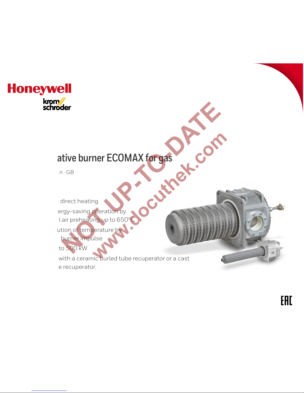
• For direct and indirect heating
• Economical, energy-saving operation by
virtue of internal air preheating up to 650°C
• Uniform distribution of temperature by
means of a high burner impulse
• 7 sizes from 25 to 500 kW
• Highly efficient with a ceramic burled tube recuperator or a cast
steel ribbed tube recuperator.
Self-recuperative burner ECOMAX for gas
Page 2

ECOMAX · Edition 10.17 2
▼
= To be continued
Contents
Self-recuperative burner ECOMA X for gas ..........1
Contents ............................................2
1 Application ........................................4
1.1 Direct heating ......................................4
1.2 Indirect heating ....................................4
1.3 Application examples ..............................5
1.4 ECOMAX for direct heating systems...............6
1.4.1 Flow rate control.......................................6
1.4.2 Air/gas ratio control....................................7
1.4.3 No pneumatic air/gas ratio control system ...........8
1.5 ECOMAX® for indirect heating systems ...........9
1.5.1 No pneumatic air/gas ratio control system .........10
1.5.2 Air/gas ratio control .................................10
2 Certification ......................................11
3 Structure .........................................12
3.1 Burner body .......................................12
3.2 Recuperator.......................................13
3.3 Air guide tube .....................................14
3.4 Gas insert .........................................15
3.5 Version overview ..................................16
4 Function ..........................................17
5 Selection ........................................ 19
5.1 Burner type .......................................19
5.2 Burner size . . . . . . . . . . . . . . . . . . . . . . . . . . . . . . . . . . . . . . . .19
5.3 Burner length .................................... 20
5.4 Burner head .......................................21
5.4.1 Use....................................................21
5.4.2 Gas type ..............................................21
5.5 Type of heating ...................................22
5.6 Connection for additional furnace cooling .......23
5.7 Electrode made of Kanthal APM..................23
5.8 Selection table ...................................24
5.8.1 ECOMAX..C.......................................... 24
5.8.2 ECOMAX..M .........................................24
5.8.3 ECOMAX..P.......................................... 25
5.8.4 ECOMAX..F..........................................25
5.8.5 Type code............................................26
5.9 Selection table for flue gas eductor EJEK ........27
5.9.1 Type code............................................28
5.10 Selection table for flue gas connector FLUP....29
5.10.1 Type code ..........................................30
6 Project planning information for direct heating ..31
6.1 Heating system design ...........................31
6.2 Flue gas guide tube FGT set ......................32
6.3 Flue gas eductor EJEK............................33
6.4 Furnace flue gas system..........................34
6.5 Installation........................................35
6.5.1 Installation position ................................ 35
6.5.2 Tangential or angled burner installation ............35
6.5.3 Clearances .......................................36
6.5.4 Furnace temperature measurement.................37
6.5.5 Heat guard ...........................................37
6.6 Flame control .....................................38
6.7 Burner control units and ignition transformers ..39
6.7.1 Burner control unit configurations ..................40
6.8 Gas connection ..................................41
6.8.1 Selecting components . . . . . . . . . . . . . . . . . . . . . . . . . . . . . . .41
6.8.2 Gas pressure .........................................41
6.8.3 Operation with LPG .................................42
6.9 Air connection ....................................43
6.9.1 Selecting components ..............................43
6.9.2 Air pressure ..........................................43
6.10 Air flow monitoring ............................. 44
6.11 Purge air and cooling air........................ 44
6.12 Condition on delivery............................45
6.13 Cooling with ECOMAX ..........................45
6.14 Emissions ...................................... 46
Page 3
ECOMAX · Edition 10.17 3
▼
= To be continued
6.15 Build up of noise................................ 46
6.16 Process boundary conditions . . . . . . . . . . . . . . . . . . . 47
6.17 Resistance of SiSiC ..............................47
7 Project planning information for indirect heating 48
7.1 Heating system design........................... 48
7.2 Radiant tubes . . . . . . . . . . . . . . . . . . . . . . . . . . . . . . . . . . . . .49
7.3 Flue gas channelling ............................. 50
7.4 Furnace flue gas system ..........................51
7.5 Installation ........................................52
7.5.1 Heat guard ...........................................52
7.6 Flame control......................................53
7.7 Burner control units and ignition transformers ...54
7.7.1 Burner control unit configurations...................55
7.8 Gas connection ...................................56
7.8.1 Selecting components...............................56
7.8.2 Gas pressure .........................................56
7.8.3 Operation with LPG ...................................57
7.9 Air connection .....................................58
7.9.1 Selecting components...............................58
7.9.2 Air pressure ..........................................58
7.10 Air flow monitoring ...............................59
7.11 Purge air and cooling air .........................59
7.12 Condition on delivery ........................... 60
7.13 Increased furnace cooling with ECOMA X..K.... 60
7.14 Build up of noise .................................61
7.15 Emissions ........................................61
8 Accessories.......................................62
8.1 Air connection set.................................62
8.2 Air flow detector set...............................62
8.3 VAH connection set ...............................63
8.4 UV adapter set ....................................63
8.5 Purge air/cooling air nozzles......................63
8.6 Flue gas guide tube FGT Set..D ...................64
8.7 Flue gas eductor EJEK............................65
8.8 Flue gas connector FLUP.........................65
8.9 Ceramic radiant tube SERC..................... 66
8.10 Segmented flame tube SICAFLEX ............. 66
8.11 Cruciform spacer ................................67
8.12 Flue gas guide tube FGT SET ECO..SERC......67
8.13 Piping........................................... 68
8.13.1 Direct heating......................................68
8.13.2 Indirect heating ....................................69
9 Technical data ................................... 70
9.1 Dimensions .......................................71
9.1.1 ECOMAX..C for direct heating........................71
9.1.2 ECOMAX..M for direct heating......................72
9.1.3 ECOMAX..F for direct heating.......................73
9.1.4 ECOMAX..C for indirect heating .................... 74
9.1.5 ECOMA X..M for indirect heating ....................75
9.1.6 ECOMAX..F for indirect heating.....................76
10 Maintenance ....................................77
Feedback ...........................................78
Contact.............................................78
Page 4

ECOMAX · Edition 10.17 4
ECOMAX..M
ECOMAX..C
Application
1 Application
Self-recuperative burners ECOMAX are used for heating
on either direct or indirect furnace systems in ON/OFF
intermittent mode. The hot flue gases are fed through
the ceramic or metallic heat exchanger, which is integrat-
ed in the burner, heating the additional supply of cold
combustion air flowing in the opposite direction. The
maximum achievable air preheat temperature amounts
to approx. 650°C, depending on the application.
1.1 Direct heating
In conjunction with an eductor EJEK to extract the flue
gases, the burner ECOMAX is used to save energy in a
direct heating system without long hot air pipes requir-
ing insulation.
Applications include heat treatment furnaces in the
iron and steel industry and in the non-ferrous metal
industr y.
1.2 Indirect heating
Self-recuperative burners ECOMAX are used in conjunction with metallic or ceramic radiant tubes and
ceramic segmented flame tubes SICAFLEX for indirect
heating. Indirect heating equipment is used whenever
the combustion gases are to be separated from the
product, e.g. in heat treatment furnaces with inert gas
atmospheres in the steel industry or when heat-treating
aluminium.
Page 5
ECOMAX · Edition 10.17 5
Application
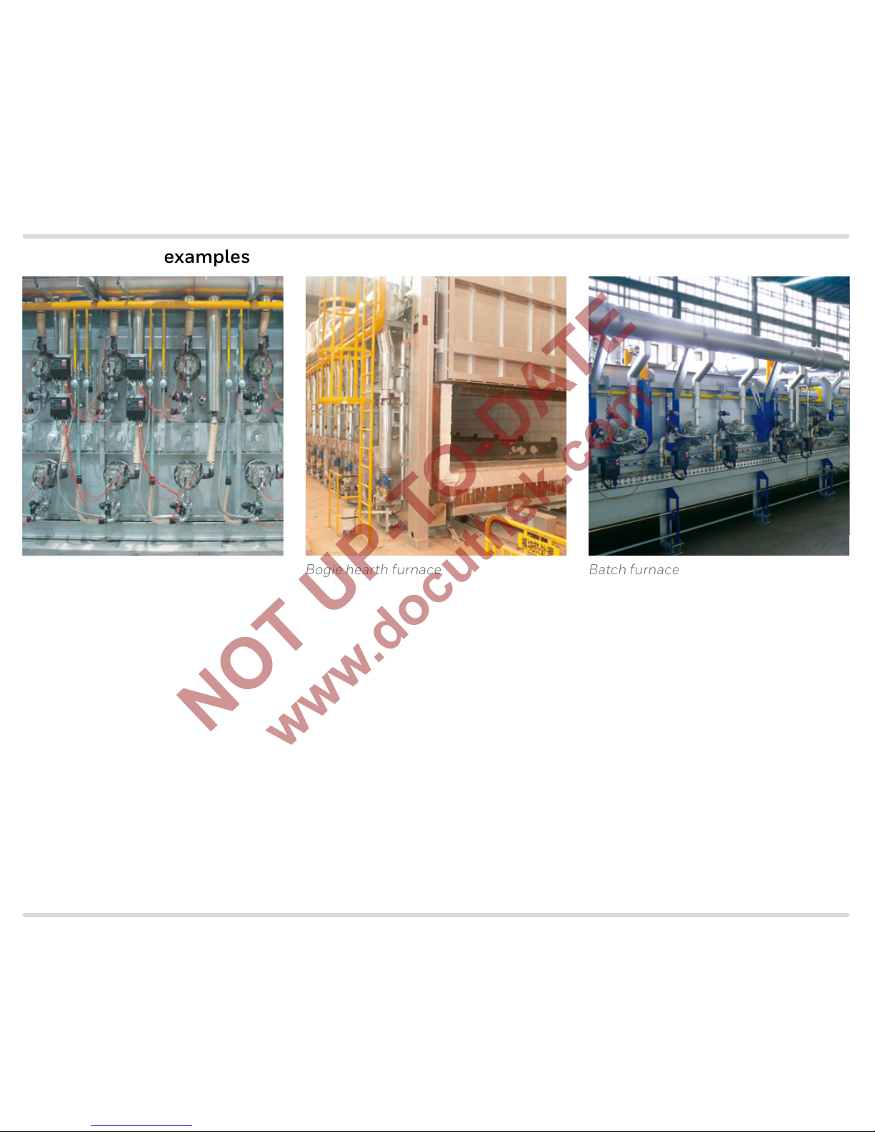
Roller hearth furnace Bogie hearth furnace Batch furnace
1.3 Application examples
Page 6
ECOMAX · Edition 10.17 6
ApplicationApplication > ECOMAX for direct heating systems
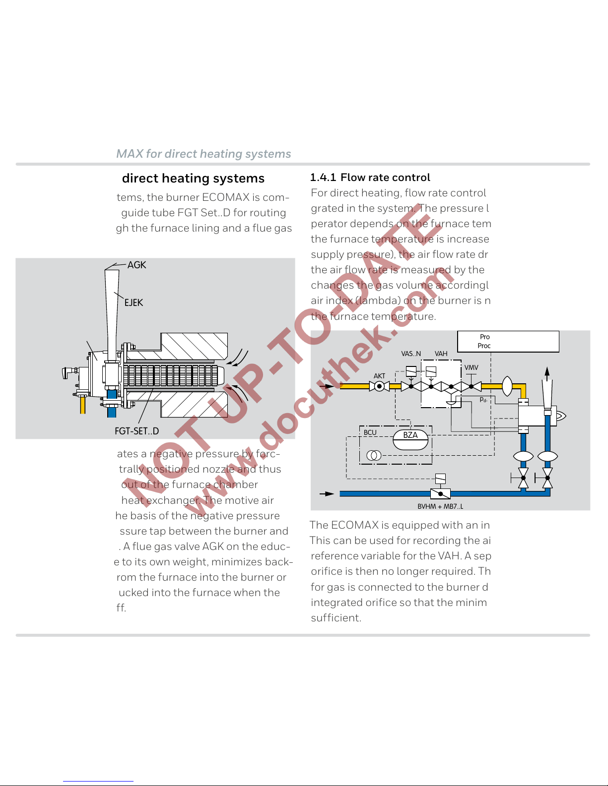
1.4 ECOMAX for direct heating systems
In direct heating systems, the burner ECOMAX is com-
bined with a flue gas guide tube FGT Set..D for routing
the flue gases through the furnace lining and a flue gas
eductor EJEK.
AGK
ECOMAX
FGT-SET..D
EJEK
Eductor EJEK generates a negative pressure by forc-
ing air through a centrally positioned nozzle and thus
draws the flue gases out of the furnace chamber
through the burner’s heat exchanger. The motive air
flow is adjusted on the basis of the negative pressure
measured on the pressure tap between the burner and
the motive air nozzle. A flue gas valve AGK on the educ-
tor, which closes due to its own weight, minimizes back-
flow of hot flue gas from the furnace into the burner or
infiltrated air being sucked into the furnace when the
burner is switched off.
1.4.1 Flow rate control
For direct heating, flow rate control should be integrated in the system. The pressure loss in the recuperator depends on the furnace temperature. When
the furnace temperature is increased (at a constant air
supply pressure), the air flow rate drops. This change in
the air flow rate is measured by the orifice and the VAH
changes the gas volume accordingly to ensure that the
air index (lambda) on the burner is not dependent on
the furnace temperature.
BVHM + MB7..L
VMV EKO
LEH
ECOMAX
VAH
BCU
BZA
Prozess-Steuerung/
Process Control (PCC)
AKT
p
sa-
p
sa
p
d-
VAS..N
The ECOMAX is equipped with an integrated air orifice.
This can be used for recording the air flow rate as a
reference variable for the VAH. A separate upstream air
orifice is then no longer required. The impulse line pdfor gas is connected to the burner downstream of the
integrated orifice so that the minimum gas pressure is
sufficient.
Page 7

ECOMAX · Edition 10.17 7
Application
1.4.2 Air/gas ratio control
If the system does not include flow rate control, tem-
perature-dependent pressure losses in the burner are
not compensated for. The air index lambda drops with
increasing furnace temperature (increasing air preheat-
ing). Therefore, in a cold furnace, an increased lambda
value is to be set to ensure sufficient excess air, even
when the furnace temperature is at its maximum. A fur-
nace at 1100°C with λ = 1.1 (approx. 2% O2) requires a
burner setting of approx. 4% O2, for example, when the
furnace is cold.
BVHM + MB7..L
VMV
ECOMAX
VAS..N
BCU
BZA
Prozess-Steuerung/
Process Control (PCC)
AKT
VAG
Page 8
ECOMAX · Edition 10.17 8
ApplicationApplication
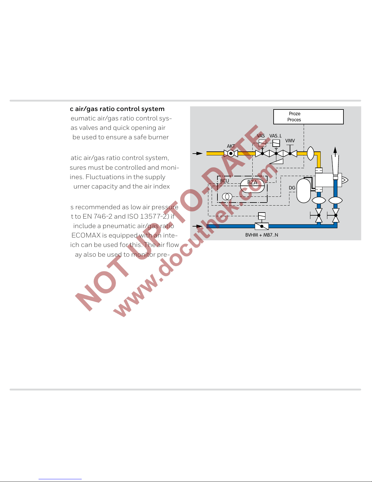
1.4.3 No pneumatic air/gas ratio control system
When there is no pneumatic air/gas ratio control sys-
tem, slow opening gas valves and quick opening air
control valves are to be used to ensure a safe burner
start.
If there is no pneumatic air/gas ratio control system,
the gas and air pressures must be controlled and moni-
tored in the supply lines. Fluctuations in the supply
pressure affect the burner capacity and the air index
(lambda).
Air flow monitoring is recommended as low air pressure
protection (pursuant to EN 7462 and ISO 135772) if
the system does not include a pneumatic air/gas ratio
control system. The ECOMAX is equipped with an inte-
grated air orifice which can be used for this. The air flow
monitoring system may also be used to monitor pre-
purge.
BVHM + MB7..N
VMV EKO
LEH
ECOMAX
VAS VAS..L
BCU
BZA
Prozess-Steuerung/
Process Control (PCC)
PDZ
DG
AKT
Page 9
ECOMAX · Edition 10.17 9
Application
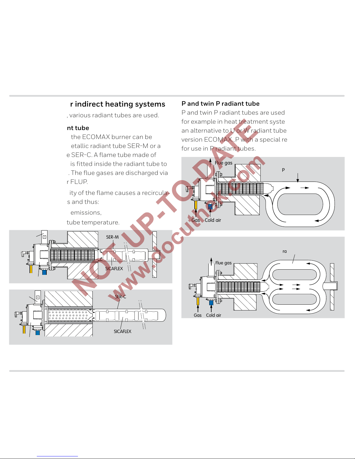
1.5 ECOMAX® for indirect heating systems
For indirect heating, various radiant tubes are used.
Single ended radiant tube
Indirect heating with the ECOMAX burner can be
carried out using a metallic radiant tube SERM or a
ceramic radiant tube SERC. A flame tube made of
SICAFLEX elements is fitted inside the radiant tube to
guide the flue gases. The flue gases are discharged via
a flue gas connector FLUP.
The high outlet velocity of the flame causes a recircula-
tion of the flue gases and thus:
– a reduction in NO
X
emissions,
– a uniform radiant tube temperature.
SER-M
FLUP
ECOMAX..M
SICAFLEX
SER-C
SICAFLEX
FLUP
ECOMAX..C
P and twin P radiant tube
P and twin P radiant tubes are used in some processes,
for example in heat treatment systems for steel strip as
an alternative to U or W radiant tubes. The new burner
version ECOMAX..P with a special recuperator head is
for use in P radiant tubes.
Gas Cold air
P radiant tube
Flue gas
Gas Cold air
Twin P
radiant tube
Flue gas
Page 10

ECOMAX · Edition 10.17 10
Application
1.5.1 No pneumatic air/gas ratio control system
For indirect heating, slow opening gas valves and quick
opening air control valves are to be used to ensure a
safe burner start.
If there is no pneumatic air/gas ratio control system,
the gas and air pressures must be controlled and moni-
tored in the supply lines. Fluctuations in the supply
pressure affect the burner capacity and the air index
(lambda).
A system which includes air flow monitoring is recom-
mended to monitor pre-purge and as low air pressure
protection (pursuant to EN 7462 and ISO 135772).
The ECOMAX is equipped with an integrated air orifice
which can be used for this.
VR..N
VMV
ECOMAX
VG VG..L
BCU
BZA
Prozess-Steuerung/
Process Control (PCC)
PDZ
DG
AKT
1.5.2 Air/gas ratio control
The pneumatic air/gas ratio control system ensures
that changes in the air pressure in the air supply line are
compensated for by controlling the gas pressure at the
burner accordingly.
VR..N
VMV VG..L
ECOMAX
BCU
BZA
Prozess-Steuerung/
Process Control (PCC)
PDZ
DG
AKT
VAG
A system which includes air flow monitoring is also
recommended to monitor pre-purge (pursuant to
EN 7462 and ISO 135772) even if there is a pneumatic
air/gas ratio control system.
Page 11
ECOMAX · Edition 10.17 11
Certification
2 Certification
Certificates – see w ww.docuthek.com.
Machinery Directive
The product ECOMAX is a partly completed machine
pursuant to Article 2g of Directive 2006/42/EC and
complies with the essential health and safety require-
ments in accordance with Annex I, as stated in the Dec-
laration of Incorporation.
Eurasian Customs Union
The product ECOMAX meets the technical specifica-
tions of the Eurasian Customs Union.
Page 12

ECOMAX · Edition 10.17 12
Structure
3 Structure
The burner ECOMAX is composed of four modules:
burner body, recuperator, air guide tube and gas insert.
The modular design facilitates adapting the burners to
the respective application or integrating them into an
existing furnace system. Maintenance and repair times
are reduced, and existing furnace installations can eas-
ily be converted.
3.1 Burner body
The burner body is made of cast aluminium, which
means it has a low weight. The housing has a double-
wall design. The combustion air is fed into the burner
via the outer annular void. This cools the burner body
and reduces emissions. A shaped part made of vacu-
um-formed ceramic fibres (RCF) is fitted in the housing
as internal insulation on the flue gas side.
From construction stage B, the ECOMAX is equipped
with two pressure taps on the air connection, which allow the differential pressure to be measured across the
orifice so that the burner can be adjusted.
Page 13

ECOMAX · Edition 10.17 13
StructureStructure
3.2 Recuperator
The burner ECOMAX is available in three versions:
– ECOMAX..C with ceramic burled tube recuperator
– ECOMAX..M and ECOMAX..P with cast steel ribbed
tube recuperator
– ECOMAX..F with metallic flat tube recuperator
Ceramic burled tube recuperator
The surface of the ceramic recuperator, which is made
of SiSiC for high thermal stress, is burled in order to
achieve high efficiency.
Cast steel ribbed tube recuperator
The ribs on the cast steel ribbed recuperator offer a
large surface area, allowing it to achieve high efficiency
even at low temperatures.
The burner version ECOMAX..P with a special recu-
perator head is available for use in P radiant tubes. The
geometry is tailored to this application to improve gas
recirculation and therefore the temperature uniformity
of the radiant tube.
Flat tube recuperator
The flat tube recuperator has a smooth surface. It is a
cost-effective alternative at a lower efficiency level.
Page 14
ECOMAX · Edition 10.17 14
Structure
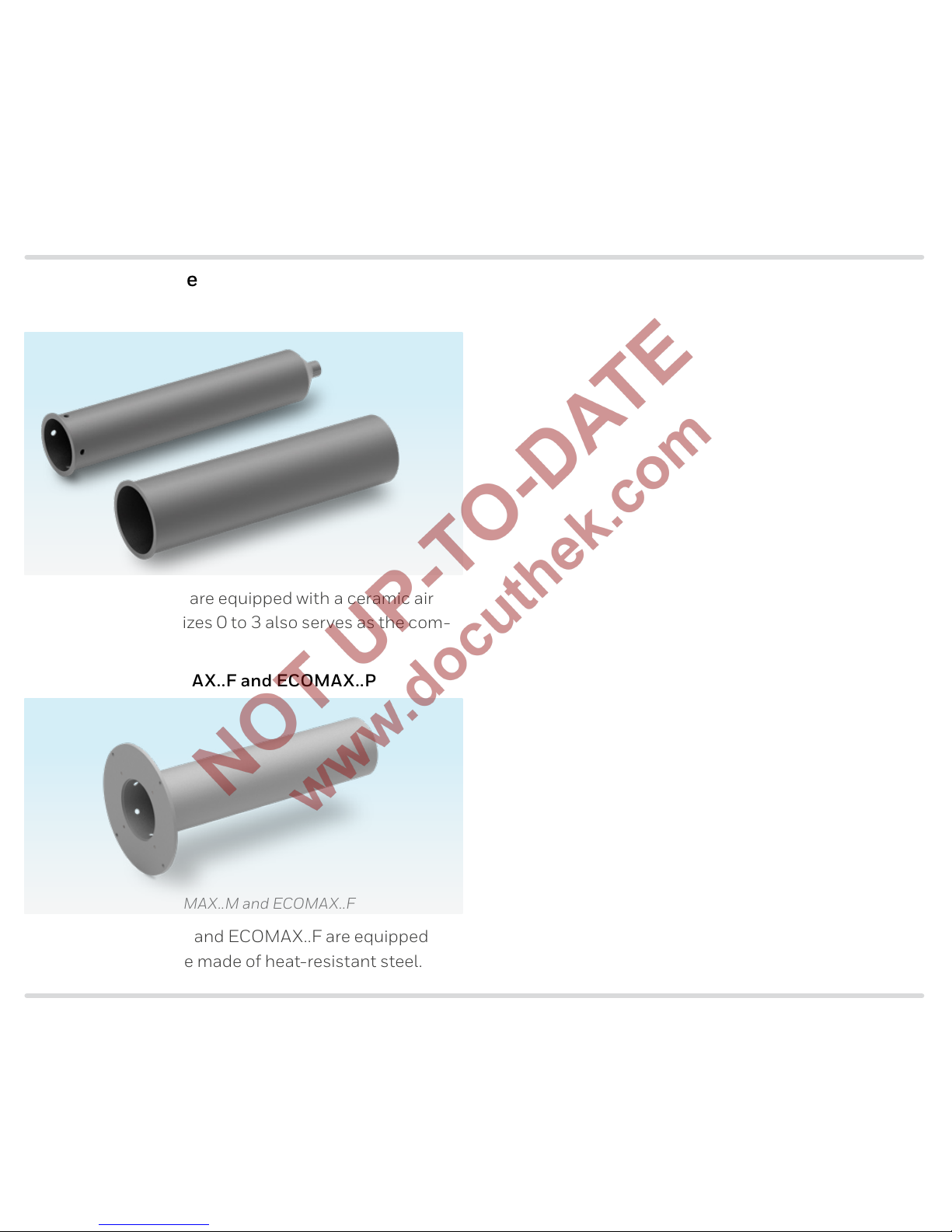
3.3 Air guide tube
ECOMA X..C
Burners ECOMAX..C are equipped with a ceramic air
guide tube that for sizes 0 to 3 also serves as the com-
bustion chamber.
ECOMA X..M, ECOMAX..F and ECOMAX..P
Air guide tube for ECOMAX..M and ECOMAX..F
Burners ECOMAX..M and ECOMAX..F are equipped
with an air guide tube made of heat-resistant steel.
Page 15

ECOMAX · Edition 10.17 15
Structure
3.4 Gas insert
The gas insert consists of the gas connection flange,
the torch with burner head and the spark electrode
(also serves as monitoring electrode). A measuring
orifice, which is integrated in the gas insert, allows for
simple measurement of the gas flow rate. The orifice is
designed depending on the gas types (see 5.4.2).
To ensure accurate measurements of the pressure
differential on the integrated orifice, flow to the ori-
fice must not be disturbed. For this reason, burners
ECOMAX are equipped as standard with a special pipe
nipple to serve as inlet section on the gas connection.
Gas insert without combustion chamber for ECOMAX..C
(sizes 0 to 3)
Gas insert with combustion chamber for ECOMAX..M
(sizes 1 to 3)
Gas insert with combustion chamber for ECOMAX
(sizes 4 to 5)
Page 16

ECOMAX · Edition 10.17 16
ECOMAX..C 0 – 3
ECOMAX..C 4 – 5
ECOMAX..M 1 – 3
ECOMAX..M 4 – 5
Structure
3.5 Version overview
Burner Size Gas insert Air guide tube
ECOMAX..C
0– 3 With mixing funnel
Ceramic,
with integrated
combustion chamber
4– 5
With swirl plate and
ceramic combustion
chamber
Ceramic
ECOMAX..M
ECOMAX..P
ECOMAX..F
1– 3
With mixing funnel
and ceramic
combustion chamber
Metallic
4– 6
With swirl plate and
ceramic combustion
chamber
Metallic
Page 17
ECOMAX · Edition 10.17 17
Function
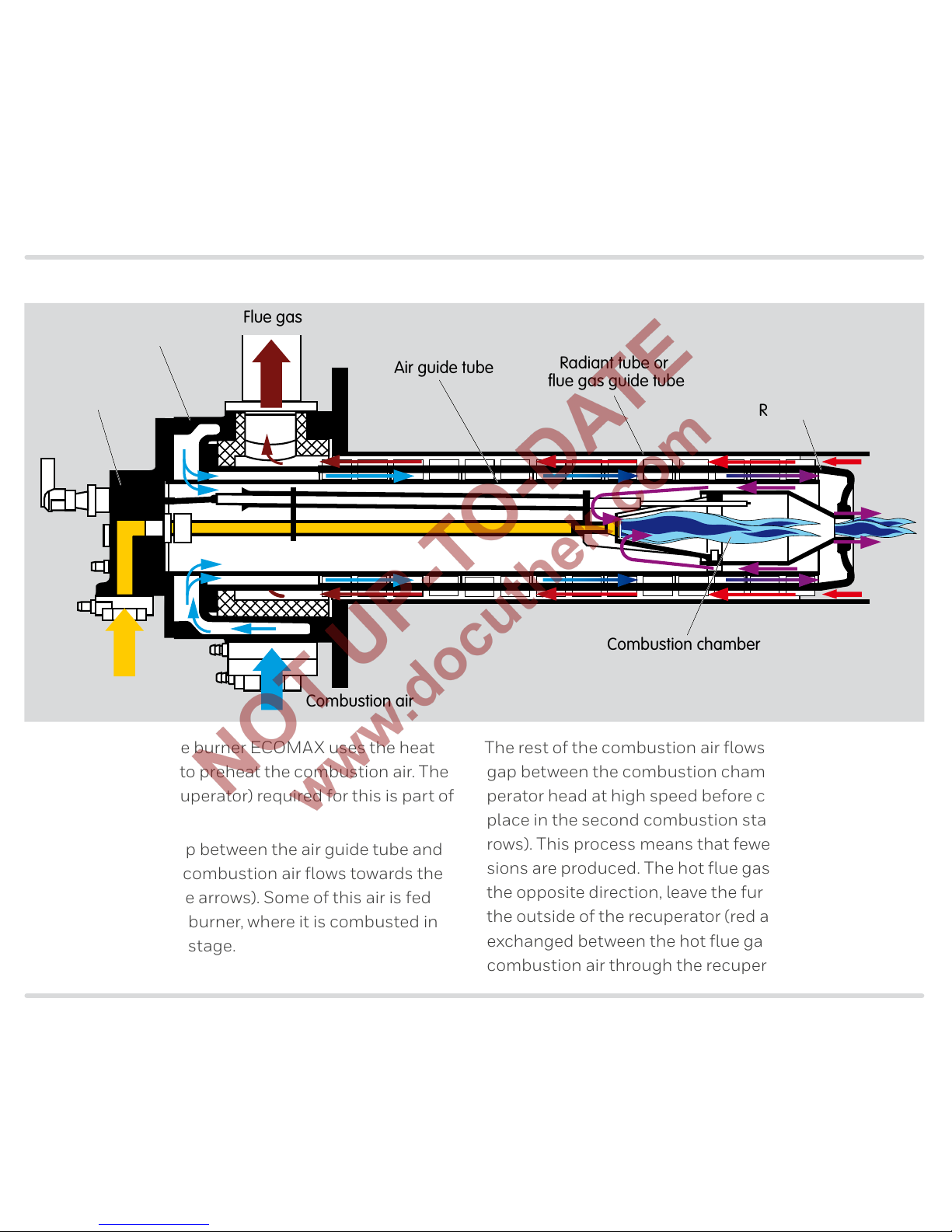
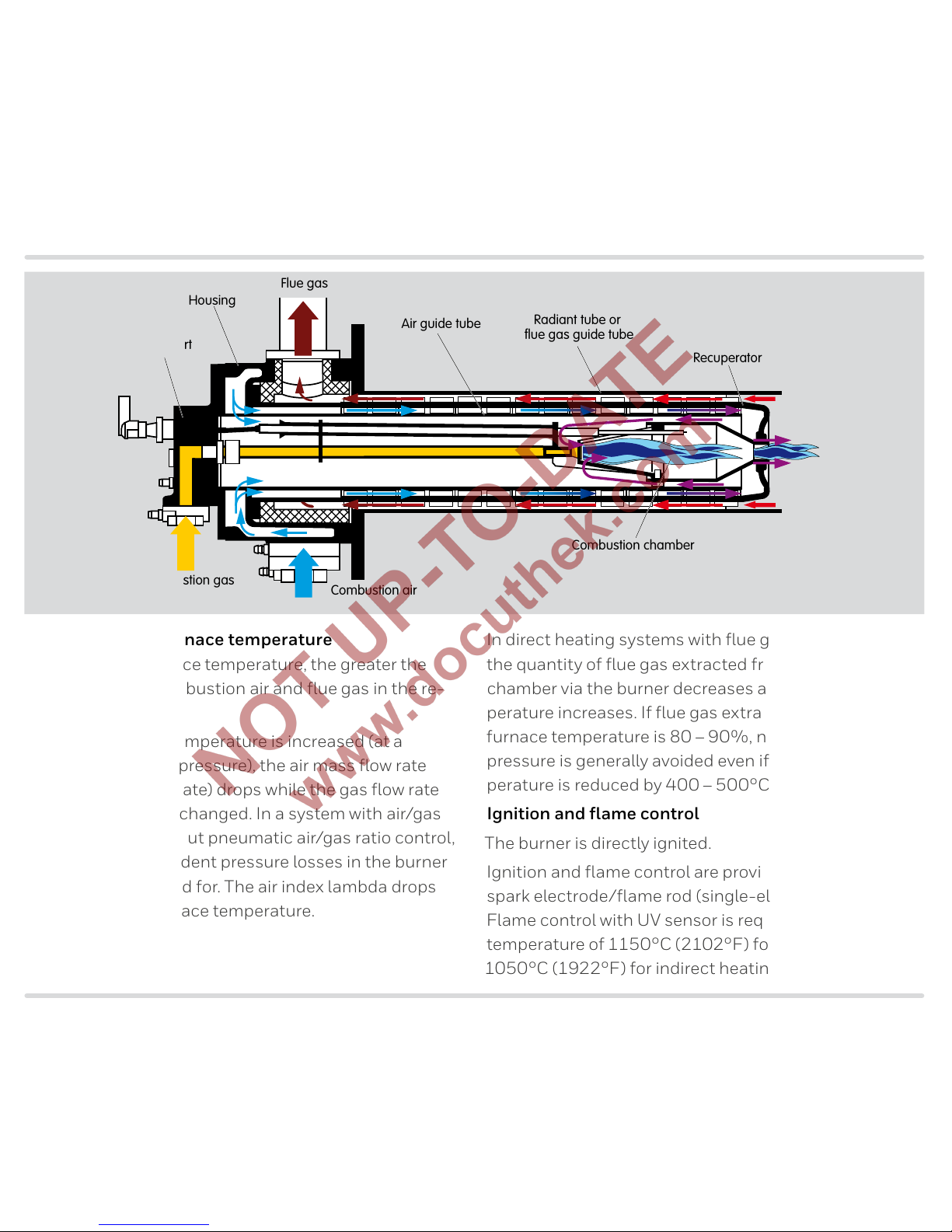
4 Function
Recuperator
Combustion chamber
Air guide tube
Radiant tube or
flue gas guide tube
Flue gas
Combustion gas
Combustion air
Housing
Gas insert
The self-recuperative burner ECOMAX uses the heat
from the flue gases to preheat the combustion air. The
heat exchanger (recuperator) required for this is part of
the burner.
After entering the gap between the air guide tube and
the recuperator, the combustion air flows towards the
tip of the burner (blue arrows). Some of this air is fed
into the inside of the burner, where it is combusted in
the first combustion stage.
The rest of the combustion air flows out through the
gap between the combustion chamber and the recuperator head at high speed before combustion takes
place in the second combustion stage here (violet arrows). This process means that fewer pollutant emissions are produced. The hot flue gases, flowing in
the opposite direction, leave the furnace chamber on
the outside of the recuperator (red arrows). Heat is
exchanged between the hot flue gases and the cold
combustion air through the recuperator wall.
Page 18
ECOMAX · Edition 10.17 18
Function
Influence of the furnace temperature
The higher the furnace temperature, the greater the
pressure loss in combustion air and flue gas in the re-
cuperator.
When the furnace temperature is increased (at a
constant air supply pressure), the air mass flow rate
(= standard air flow rate) drops while the gas flow rate
remains virtually unchanged. In a system with air/gas
ratio control or without pneumatic air/gas ratio control,
temperature-dependent pressure losses in the burner
are not compensated for. The air index lambda drops
with increasing furnace temperature.
In direct heating systems with flue gas eductor EJEK,
the quantity of flue gas extracted from the furnace
chamber via the burner decreases as the furnace temperature increases. If flue gas extraction at maximum
furnace temperature is 80–90%, negative furnace
pressure is generally avoided even if the furnace temperature is reduced by 400–500°C.
Ignition and flame control
The burner is directly ignited.
Ignition and flame control are provided by a combined
spark electrode/flame rod (single-electrode operation).
Flame control with UV sensor is required if a furnace
temperature of 1150°C (2102°F) for direct heating or
1050°C (1922°F) for indirect heating is exceeded.
Recuperator
Combustion chamber
Air guide tube
Radiant tube or
flue gas guide tube
Flue gas
Combustion gas
Combustion air
Housing
Gas insert
Page 19

ECOMAX · Edition 10.17 19
Selection
5 Selection
5.1 Burner type
Selection is dependent on the type of heating and
the furnace temperature. Details on selection, see
page 31 (Heating system design) for direct heat-
ing or page 48 (Heating system design) for indirect
heating.
Burner Max. flue gas temperature at recuperator inlet
[°C] [°F]
ECOMAX..C 1250 2282
ECOMAX..M
ECOMAX..P
1150 2102
ECOMAX..F 1050 1922
5.2 Burner size
Burner
Size
Capacity
1)
Recuperator
kW
2)
103 BTU/h
3)
C M P F
ECOMA X 0 25 95
– – –
ECOMA X 1 36 136
–
ECOMA X 2 60 227
ECOMA X 3 100 378
ECOMA X 4 180 681
ECOMA X 5 250 945
–
ECOMA X 6 500 1890 –
– –
= available
1)
For operation with natural gas. For operation with coke oven gas,
the capacity is approx. 80%, for operation with LCV gas, approx.
65%.
2)
Capacities in kW refer to the lower calorific value Hu.
3)
Capacities in BTU/h refer to the upper calorific value Ho.
When using the burner in geodetic ranges over 500 m
above MSL, the possible capacity is reduced due to
a decrease in the density of gas and air. Guide value:
reduction of 5% per 1000 m above MSL, more details
on request.
Page 20
ECOMAX · Edition 10.17 20
SelectionSelection
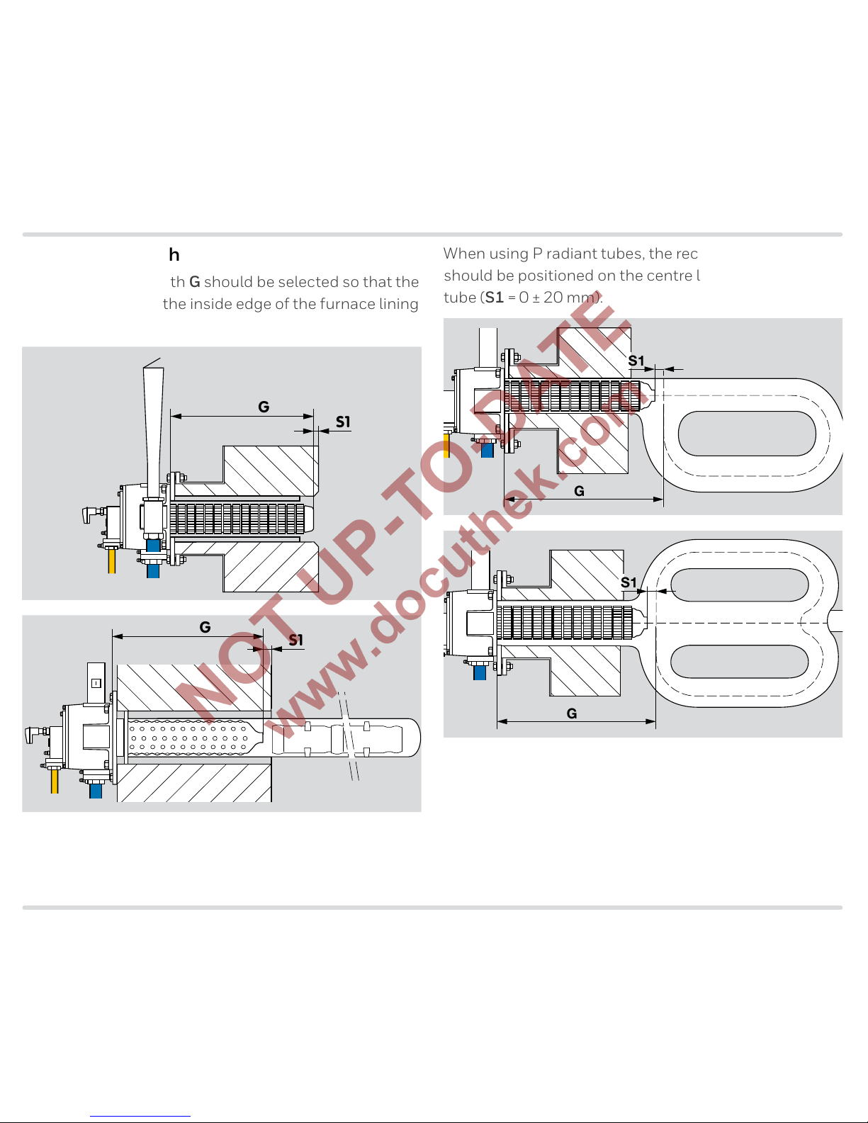
5.3 Burner length
The recuperator length G should be selected so that the
burner is flush with the inside edge of the furnace lining
(S1 = 0 ± 20 mm).
S1
G
S1
G
When using P radiant tubes, the recuperator head
should be positioned on the centre line of the radiant
tube (S1 = 0 ± 20 mm).
S1
G
S1
G
Page 21

ECOMAX · Edition 10.17 21
SelectionSelection
5.4 Burner head
5.4.1 Use
The burner ECOMAX can be equipped with 2 different
burner heads. Stage combustion is standard. For some
burner variants, a menox version is also possible, which
allows for switchover to menox® low NOX mode with
flameless combustion when the furnace temperature
exceeds 850°C in a direct heating system.
Use Burner head code letter
Standard flame mode S
menox
®
low NOX mode
1)
M
1)
menox® low NOX mode on request.
5.4.2 Gas type
Gas type Code letter Calorific value range
Density ρ
kWh/m
3
(n)
2)
BTU/scf
3)
kg/m3(n) lb/scf
Natural gas L and H quality B 8– 12 810– 1215 0.7– 0.9 0.041– 0.053
Propane, propane/butane, butane G 25– 35 2560– 3474 2.0– 2.7 0.118– 0.159
Coke oven gas, town gas D 4– 5 421– 503 0.4– 0.6 0.024– 0.035
Low calorific value gas L 1.7
1)
–3 161– 290 0.9– 1.15 0.053– 0.068
1)
Calorific value range < 1.7 on request.
2)
Calorific value ranges in kWh/m3 refer to the
lower calorific value Hu.
3)
Calorific value ranges in BTU/SCF refer to the
upper calorific value Ho.
Page 22
ECOMAX · Edition 10.17 22
Selection
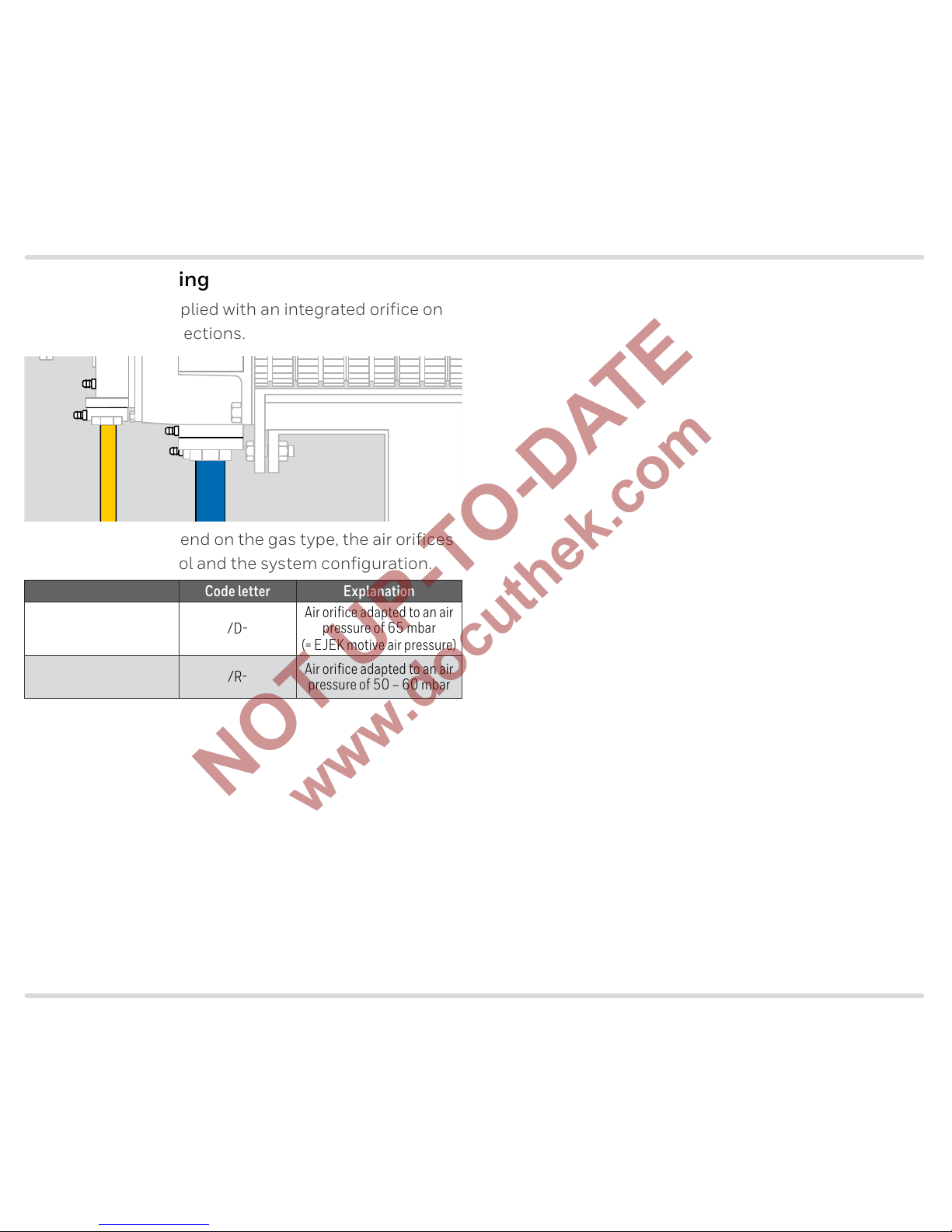
5.5 Type of heating
The ECOMAX is supplied with an integrated orifice on
the gas and air connections.
The gas orifices depend on the gas type, the air orifices
on the type of control and the system configuration.
Type of heating Code letter Explanation
Direct heating with
eductor
/D
Air orifice adapted to an air
pressure of 65 mbar
(= EJEK motive air pressure)
Indirect heating without
an eductor
/R
Air orifice adapted to an air
pressure of 50 – 60 mbar
Page 23
ECOMAX · Edition 10.17 23
Selection
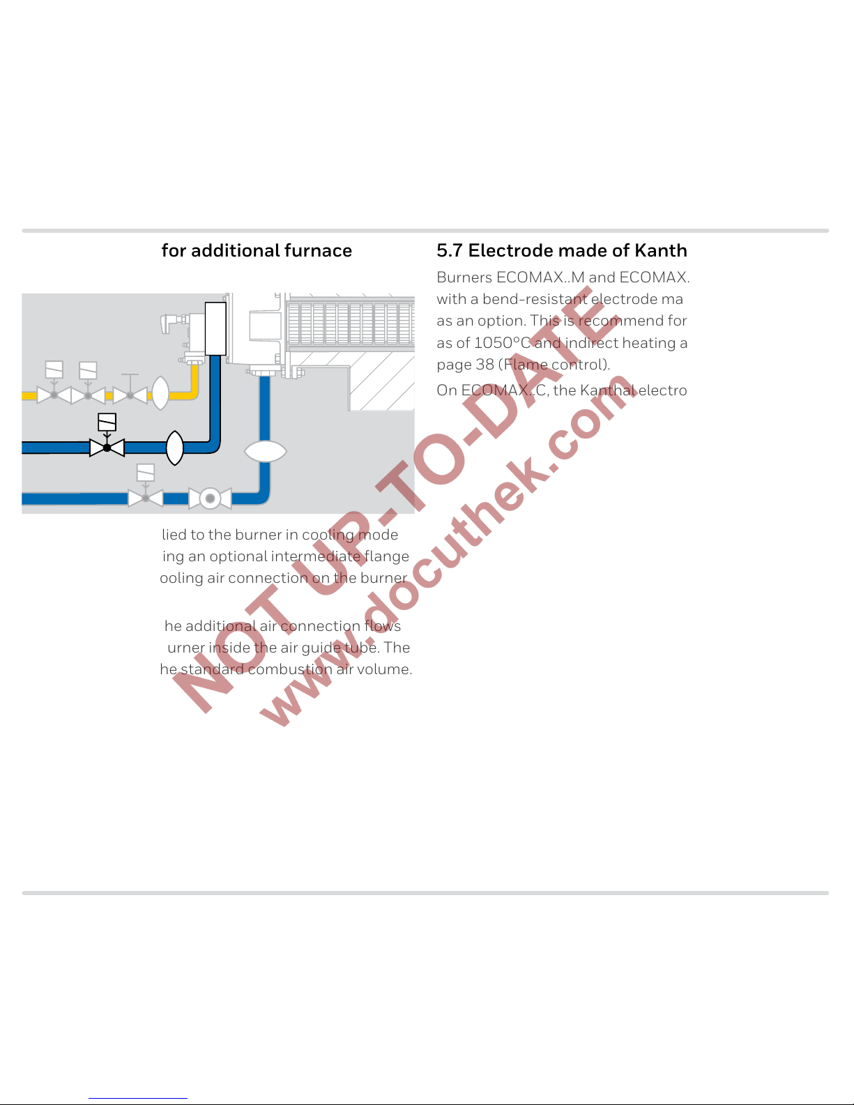
5.6 Connection for additional furnace
cooling
The air volume supplied to the burner in cooling mode
can be increased using an optional intermediate flange
with an additional cooling air connection on the burner
ECOMAX.
The air supplied via the additional air connection flows
in the centre of the burner inside the air guide tube. The
air volume is twice the standard combustion air volume.
5.7 Electrode made of Kanthal APM
Burners ECOMAX..M and ECOMAX..P can be equipped
with a bend-resistant electrode made of Kanthal APM
as an option. This is recommend for direct heating
as of 1050°C and indirect heating as of 950°C, see
page 38 (Flame control).
On ECOMA X..C, the Kanthal electrode is standard.
Page 24

ECOMAX · Edition 10.17 24
Selection
5.8 Selection table
5.8.1 ECOMAX..C
395 475 545 556 593 613 617 636 641 681 689 S B D G L1)/D /R (1–99) A–E – K T
ECOMA X 0C
● ● ● ● ● ● ● ● ● ● ● ●
ECOMA X 1C
● ● ● ● ● ● ● ● ● ● ● ●
ECOMAX 2C
● ● ● ● ● ● ●
● ● ● ●
ECOMA X 3C
● ● ● ● ● ● ●
● ● ● ●
ECOMA X 4C
● ● ● ● ●
● ● ● ●
ECOMAX 5C
● ● ● ● ●
● ● ● ●
1)
On request.
ECOMA X..C is supplied with Kanthal electrodes as standard.
●
= standard, = available
Order example
ECOMA X 1C545SB/R(31)B
5.8.2 ECOMA X..M
545 595 645 695 S M B D G L1)/D /R (1–99) A–E – K A T
ECOMAX 1M
● ● ● ● ● ● ● ● ● ● ● ●
ECOMAX 2M
● ● ● ● ● ● ● ●
● ● ● ●
ECOMA X 3M
● ● ● ● ●
● ● ●
● ● ● ●
ECOMAX 4M
● ● ● ● ●
● ● ●
● ● ● ●
ECOMAX 5M
● ● ●
● ● ●
● ● ● ●
ECOMA X 6M
●
● ● ● ●
● ● ● ●
1)
On request.
●
= standard, = available
Order example
ECOMA X 3M545SB/D(34)B
Page 25

ECOMAX · Edition 10.17 25
Selection
5.8.3 ECOMAX..P
645 695 S B D G L
1)
/R (1–99) A–E – K T
ECOMAX 2P
● ● ●
●
● ● ●
ECOMA X 3P
● ● ●
●
● ● ●
ECOMAX 4P
● ● ●
●
● ● ●
1)
On request.
●
= standard, = available
Order example
ECOMA X 3P695SB/R(34)B
5.8.4 ECOMAX..F
545 595 645 695 S B D G L
1)
/D /R (1–99) A–E – K T
ECOMAX 1F
●
● ●
● ● ● ● ●
ECOMAX 2F
●
● ●
●
● ● ● ●
ECOMA X 3F
●
● ●
●
● ● ● ●
ECOMAX 4F
●
● ●
●
● ● ● ●
ECOMAX 5F
●
● ●
●
● ● ● ●
1)
On request.
●
= standard, = available
Order example
ECOMA X 3F545SB/D(34)B
Page 26

ECOMAX · Edition 10.17 26
Selection
5.8.5 Type code
Code Description
ECOMAX Self-recuperative burner for gas
0– 6 Burner size
C
M
P
F
Ceramic burled tube recuperator made of SiSiC
Cast steel ribbed tube recuperator
Cast steel ribbed tube recuperator for P radiant tube
Flat tube recuperator, metallic
E Special recuperator version
395– 695 Recuperator length in mm
S
M
1)
Standard fl ame
menox® low NOX operation
B
D
G
L
1)
Gas type2):
natural gas
coke oven gas
LPG
LCV gas
/D
/R
/V
/E
/nnn/N
For direct heating with eductor
For radiant tube heating without eductor
For radiant tube heating with VAH
Burner with customized orifi ces
Burner construction stage X for nnn kW
Burner without orifi ces
(1–99) Burner head identifi er
X, A, B, … Construction stage
– The following features differ from the standard version:
K
Additional cooling air connection for increased furnace
cooling
A Electrode made of Kanthal APM
T NPT connections
S SICAFLEX spacer
W Air connection without intermediate fl ange
Z Special version
1)
On request.
2)
Other t ypes of gas on request.
Page 27

ECOMAX · Edition 10.17 27
Selection
5.9 Selection table for flue gas eductor EJEK
Axis spacing Kxxx* Height Tzzz* H V 3* * 9** F.. R.. AGK HT*** A B S
EJEK 0 - K269
- M625
● ● ● ●
EJEK 1 - K269
- M625
● ●
● ● ●
EJEK 2 - K285
- M540
● ●
● ● ● ●
EJEK 3 - K292
- M620
● ● ● ●
EJEK 4 - K345
- M920
● ● ● ●
EJEK 5 - K345
- M1165
● ● ● ●
EJEK 6 - K530
- M1618
● ● ● ●
* Special dimensions on request.
* Only relevant for special dimension Tzzz.
*** HT version for ECOMAX..C.
●
= standard, = available
Order example
EJEK 4K345M920AGKHTAS
Page 28

ECOMAX · Edition 10.17 28
Selection
5.9.1 Type code
Code Description
EJEK Flue gas eductor
0– 6 Size for ECOMAX 1 – 6
Kxxx Axis spacing K in mm
Myyy Height M in mm
Tzzz* Distance T in mm
H
V
Burner installation position:
horizontal
vertical
3
9
Installation on the burner**:
right-hand side
left-hand side
F5 to F15
R5 to R15
Eductor angle in °:
pointing towards furnace
pointing away from furnace
AGK With fl ue gas valve
HT*** High temperature version
A
B
Construction stage
S Standard dimension
* If “none”, this letter is omitted.
** Only required for special dimension Tzzz.
*** HT version for ECOMA X..C.
MKM
KT
M
Page 29

ECOMAX · Edition 10.17 29
Selection
5.10 Selection table for flue gas connector FLUP
32 50 65 100 D F Kxxx Installation height Myyy* Tzzz* H** V** 0** 3** 9** C A HT B S
FLUP 0
● ●
-M230
●
● ●
FLUP 1–2
● ●
-M331
●
●
FLUP 3
● ●
-M353
●
●
FLUP 4–5
● ●
-M399
●
●
* Special dimensions on request.
** Only relevant for special dimensions K xxx and/or Tzzz.
●
= standard, = available
Order example
FLUP 365DM3530S
Page 30

ECOMAX · Edition 10.17 30
Selection
5.10.1 Type code
Code Description
FLUP Flue gas connector
0
1/2
3
4/5
For ECOMAX 0–5
32 to 100 Nominal size
D
F
Pipe connector
Flange to ISO 7005
Kxxx Axis spacing K in mm
Myyy Installation height M in mm
Tzzz* Distance T in mm
H
V
Burner installation position:
horizontal
vertical
0
3
9
Installation on the burner**:
top
right-hand side
left-hand side
C
A
Measuring port with sealing clip
Threaded pressure tap with cap
HT High temperature version
A
B
Construction stage
S Standard dimension
* If “none”, this letter is omitted.
** Only required for special dimension Tzzz.
DN
K
M
M
DN
T
DN
M
Page 31

ECOMAX · Edition 10.17 31
Project planning information for direct heating
6 Project planning information for direct heating
6.1 Heating system design
Selection of the burner type is dependent on the fur-
nace temperature.
Burner
Recommended
range of use
Max. flue gas temperature at
recuperator inlet
[°C] [°F] [°C] [°F]
ECOMAX..C up to 1250 up to 2282 1250 2282
ECOMAX..M up to 1100 up to 2012 1150 2102
ECOMAX..F up to 1000 up to 1832 1050 1922
Burners ECOMAX..M (sizes 1 to 5) and ECOMAX..F can
be used for furnace temperatures up to the max. appli-
cation temperature if it is ensured that the burner head
cannot overheat, e.g. due to burners positioned oppo-
site the ECOMAX or non representative temperature
measurements, see also page 37 (Furnace tempera-
ture measurement).
Selection of the burner size is dependent on the net
heat output. From this, the required burner capacity is
calculated using the firing efficiency value.
Net heat output [kW]
= Burner capacity [kW]
Firing efficiency η
400 500 600 700 800 900 1000 1100
0
0,1
0,2
0,3
0,4
0,5
0,6
0,7
0,8
0,9
1
1200
1300
1400
F
M
C
Firing efficiency η
Flue gas temperature on recuperator inlet [°C]
Cold air burner
Details on heating system design on request.
Page 32

ECOMAX · Edition 10.17 32
Project planning information for direct heating
6.2 Flue gas guide tube FGT set
The furnace flue gases are routed by the flue gas guide
tube through the furnace lining via the recuperator. The
FGT set must be ordered separately and is not included
in the burner delivery, see page 64 (Flue gas guide
tube FGT Set..D).
The flange thickness P1 of the flue gas guide tube is
15 mm. Plan the length of the furnace extension M1 so
that the front edge of the recuperator is flush with the
inside edge of the furnace lining (S1 = 0 ± 20 mm).
∅A
G
P1
S1
FGT-Set
Burner FGT OD A in mm
ECOMA X 0C 142
ECOMA X 1C 180
ECOMAX 2C 200
ECOMA X 3C 236
ECOMA X 4C 300
ECOMAX 5C 336
Force must not be applied to the flue gas guide tube by
the furnace lining.
When installing the FGT, the tube must be wrapped in
a ceramic fibre blanket so as to ensure that no hot furnace atmosphere may reach the furnace wall or furnace
extension. The installation opening in the furnace wall
must thus be larger than the FGT outside diameter A,
leaving an annular gap corresponding to the size of the
fibre blanket, e.g. 25 mm.
S1
∅A
P1
G
M1
FGT-Set
Burner FGT OD A in mm
ECOMAX 1M/ECOMAX 1F 133
ECOMAX 2M/ECOMAX 2F 156
ECOMA X 3M/ECOMA X 3F 193
ECOMAX 4M/ECOMAX 4F 254
ECOMAX 5M/ECOMAX 5F 287
ECOMA X 6M/ECOMA X 6F 390
Page 33

ECOMAX · Edition 10.17 33
Project planning information for direct heating
6.3 Flue gas eductor EJEK
Flue gas eductor EJEK is available in 2 versions. The
standard version EJEK is used in conjunction with
ECOMAX..M and ECOMAX..F. The high temperature
version EJEK..HT is intended for use in conjunction
with ECOMAX..C.
The eductors serve to extract the flue gas via the burner
ECOMAX and cannot be used for furnace pressure con-
trol. We recommend discharging 10 to 20% of the flue
gases via an additional flue gas opening on the furnace
fitted with a furnace pressure control system.
With 80 to 90% flue gas extraction at max. furnace
temperature, a positive furnace pressure can generally
be maintained even at low furnace temperatures. In the
case of heavily leaking furnaces, flue gas extraction
must be reduced, where necessary, to avoid pulling in
cold air due to negative pressure in the furnace cham-
ber.
p
FG
p
atm
p
FG
0
p
FG
The motive air is set at the eductor by measuring the negative
flue gas pressure pFG between the burner and eductor.
If the furnace temperature is too high, damage can occur to burners which are switched off due to the flow of
hot flue gases over them.
For direct heating, eductors EJEK..AGK with mechanical flue gas valve (AGK) are recommended so as to
avoid gas creepage while the burner is switched off.
Page 34

ECOMAX · Edition 10.17 34
Project planning information for direct heating
6.4 Furnace flue gas system
A flue gas system must be fitted on the furnace as a
means of guiding the flue gas to the chimney. In the
flue gas system there should be a low negative pressure
thanks to the draught of the chimney or an exhaust fan.
The flue gas system on the furnace should be fitted
flush with the eductor (± 10 mm). The diameter of the
flue gas pipe on the furnace should be twice the educ-
tor diameter P. If the diameter is too small, even with
the EJEK..AGK with flue gas valve there is the danger of
hot flue gases creeping through the burner when it is
switched off.
The branch lines from the furnace flue gas manifold to
the individual burners should be designed such that
condensate cannot seep upstream into the burner.
∅P
∅2P
0 mm (±10 mm)
∅1,5P
∅P
∅2P
0 mm
(±10 mm)
∅ P [mm]
ECOMA X 0 EJEK 0(B) 43
ECOMA X 1 EJEK 1 43
ECOMA X 2 EJEK 2(A) 83
ECOMA X 3 EJEK 3(A) 98
ECOMA X 4 EJEK 4(A) 128
ECOMA X 5 EJEK 5(A) 153
ECOMA X 6 EJEK 6(A) 215
Page 35

ECOMAX · Edition 10.17 35
Project planning information for direct heating
6.5 Installation
6.5.1 Installation position
15°
0°
90°
The burner ECOMAX can be installed in any position
between 0° (horizontal) and 90° (vertical from top to
bottom). The ECOMAX may be oriented upwards at an
angle of max. 15° from the horizontal.
Eductor EJEK installation position:
vertical, max. angle 10°.
If the burner is installed at an angle of more than 10°
from the vertical or horizontal, a special version of flue
gas eductor EJEK is required. This is available on re-
quest.
6.5.2 Tangential or angled burner installation
If the burner is installed tangentially or at an angle, an
opening should be provided in the furnace lining to
ensure unobstructed flue gas extraction. The choice of
furnace lining in this area should take account of the
burner’s very high outlet velocity. In addition, reflection
from the furnace wall to the burner must be considered.
B
1,5 x B
Page 36

ECOMAX · Edition 10.17 36
Project planning information for direct heating
6.5.3 Clearances
Y
X
X
X
2
X
X
RZ
Allow for adequate clearance from the charge and the
interior furnace wall so as to ensure complete combus-
tion and avoid local overheating. Due to the high air
preheat temperature of the ECOMAX, the flame tem-
perature is also higher than usual.
Z
2
Z
X
The minimum lateral clearance between two burners
or between a burner and the furnace side wall is de-
termined by the geometric dimensions of the burners
including the eductor.
In addition, it must be noted that burners facing each
other can cause overheating of the recuperator heads.
Flame mode
Burner
Reaction zone RZ (mm)
Clearance (mm)
X Z
ECOMA X 0 500 130 270
ECOMA X 1 700 155 270
ECOMA X 2 900 200 285
ECOMA X 3 1200 250 300
ECOMA X 4 1600 340 350
ECOMA X 5 1800 400 400
ECOMA X 6 2200 570 570
For menox® low NOX mode, a sufficiently large reaction
zone (RZ) and undisturbed recirculation of the flue gas
into the reaction zone are required. Operation in very
small combustion chambers leads to an increase in
NOX emissions.
menox
®
low NOX mode
Burner
Reaction zone RZ (mm)
Clearance (mm)
X Y Z
ECOMA X 3M 2100 300 320 300
ECOMAX 4M 2800 360 400 360
ECOMAX 5M 3300 400 480 400
Page 37

ECOMAX · Edition 10.17 37
Project planning information for direct heating
6.5.4 Furnace temperature measurement
Measurement of the furnace temperature must be
representative for the flue gas temperature in the ex-
traction zone on the burner. If measurement is not rep-
resentative, this will involve a risk of overheating of the
recuperator head.
6.5.5 Heat guard
During operation, the burner body and eductor or flue
gas connector can reach surface temperatures of
over 80°C. Do not insulate the burner, eductor and flue
gas connector to prevent material overheating.
We recommend that warning signs and a contact guard
be fitted, for example made of perforated sheet metal.
Page 38

ECOMAX · Edition 10.17 38
Project planning information for direct heating
6.6 Flame control
Burners ECOMAX are equipped with a combined spark
electrode/flame rod. For direct heating, ionization con-
trol is possible up to a temperature of 1150°C (single-
electrode operation). In this respect, it must be noted
that the burner control unit BCU must feature at least
firmware version FW 16xx, see page 39 (Burner con-
trol units and ignition transformers).
Flame control with UV sensor is only necessary if fur-
nace temperatures of 1050°C for direct heating or
1150 °C for indirect heating are exceeded.
We also recommend using bend-resistant Kanthal
electrodes for ignition on ECOMA X..M as of a furnace
temperature of more than 1050°C. These are fitted as
standard on ECOMAX..C.
We recommend the UV sensor UVS 10D1 with integrated purge air connection (Order No. 84315202) for
UV control.
For ECOMA X 0, the UV sensor UVS 10L1 (Order
No. 84315203) with lens is required for UV control. For
burners ECOMAX 1 –6 with a burner length of more
than 545 mm, the UV sensor UVD 10L1 with lens is
also required for UV control.
An adapter set is required for connection to the UVS 10,
see page 63 (UV adapter set).
Page 39

ECOMAX · Edition 10.17 39
Project planning information for direct heating
6.7 Burner control units and ignition
transformers
ECOMAX burners with burner control unit BCU
ECOMAX burners are designed for On/Off control.
We recommend burner control unit BCU 460..L or
BCU 465..L. In order to be able to carry out ionization
control up to 1150°C, the burner control unit must be
equipped with firmware FW 16xx or higher.
For burners ECOMAX..K with additional cooling air
connection, we recommend using burner control unit
BCU..C with additional circuit board for signal distribution.
For ignition, the ECOMAX burners require an ignition
transformer with 7.5 kV high voltage and an output current of 20 mA. An appropriate ignition transformer is
already integrated in burner control units BCU 460..8
and BCU 465..8.
For further information on burner control units and ignition transformers, see www.docuthek.com, Technical
Information BCU 460, 465.
Page 40

ECOMAX · Edition 10.17 40
Project planning information for direct heating
6.7. 1 Burner control unit configurations
Description Configuration D1 Configuration D2 Configuration D3 Configuration D4
Flame control Ionization UVS 10 Ionization U VS 10
Pneumatic air/gas ratio control VAH/ VAG VAH/VAG None/VAH/VAG None/VAH/VAG
Air flow monitoring – –
Differential pressure switch PDZ Differential pressure switch PDZ
Hardware BCU 460..L BCU 460..L BCU 465 BCU 465
Ignition transformer 8 = TZI 7,520/33 8 = TZI 7,520/33 8 = TZI 7,520/33 8 = TZI 7,520/33
Rewiring for electrode operation 1 electrode 2 electrodes 1 electrode 2 electrodes
Description Parameter Configuration D1 Configuration D2 Configuration D3 Configuration D4
Switch-off threshold of the flame amplifier 04
4 μA 4 μA 4 μA 4 μA
Air flow monitoring during purging 06 N /A N/A 1 1
Air flow monitoring during operation 07 N/A N/A 1 1
Delayed air flow monitoring 08 N/A N /A 1 1
Safety time during operation t
SB
for V1 and V2 14 1 1 1 1
Minimum burner on time t
B
20 8 8 8 8
Minimum burner pause time t
BP
21 4 4 4 4
Safety time on start-up t
SA
22 3 3 3 3
Air valve control 30 1 1 1 1
Air valve can be activated externally on start-up 31 1 1 1 1
Low fire over-run time t
KN
after a controlled shut-down 36 N/A N/A 0 0
Pre-ventilation time t
VL
before start-up 37 N/A N/A 0 0
Post-ventilation time t
NL
after a controlled shut-down 38 N /A N/A 0 0
Pre-ventilation time after safety shut-down 39 N/A N/A 0 0
Pre-ventilation for restart/start-up attempts 40 N/A N/A 0 0
Pre-ventilation after reset 41 N/A N/A 0 0
BCU for direct heating Configuration D1 Configuration D2 Configuration D3 Configuration D4
230 V 88613276 88614259 88614263 88614267
230 V, Profibus 88611901 88613865 88614264 88614268
230 V, HT operation 88614257 88614260 88614265 88614269
230 V, HT operation, Profibus 88611887 88611883 8 861426 6 88614270
Page 41

ECOMAX · Edition 10.17 41
Project planning information for direct heating
6.8 Gas connection
6.8.1 Selecting components
To ensure a safe burner start, use a pneumatic air/gas
ratio controller together with a slow opening air valve. If
there is no pneumatic air/gas ratio control system, use
a slow opening gas valve and a quick opening air valve.
The following gas valves are recommended for natural
gas:
Burner Flow rate control
Air/gas ratio
control
No pneumatic air/
gas ratio control
system
ECOMA X 0
VAS 115..N +
VAH 115..B +
VMV 115
VAS 115..N +
VAG 115..B +
VMV 115
VG 15..N +
VG 15..L +
VMV 115
ECOMA X 1
VAS 115..N +
VAH 115..B +
VMV 115
VAS 115..N +
VAG 115..B +
VMV 115
VG 15..N +
VG 15..L +
VMV 115
ECOMA X 2
VAS 115..N +
VAH 115..B +
VMV 115
VAS 115..N +
VAG 115..B +
VMV 115
VG 15..N +
VG 15..L +
VMV 115
ECOMA X 3
VAS 115..N +
VAH 115..B +
VMV 115
VAS 115..N +
VAG 115..B +
VMV 115
VG 15..N +
VG 15..L +
VMV 115
ECOMA X 4
VAS 120..N +
VAH 120..A +
VMV 120
VAS 120..N +
VAG 120..B +
VMV 120
VAS 120..N +
VAS 120..L +
VMV 120
ECOMA X 5
VAS 125..N +
VAH 125..A +
VMV 125
VAS 125..N +
VAG 125..B +
VMV 125
VAS 125..N +
VAS 125..L +
VMV 125
ECOMAX 6*
VAS 240..N +
VAH 240..A +
VMV 240
VAS 240..N +
VAG 240 +
VMV 240
VAS 240..N +
VAS 240..L +
VMV 240
* As of 360 kW, ignition with a start rate of < 33% is required
(pursuant to EN 746-2 and ISO 13577-2); a pneumatic ratio
control system and a BVH with IC 40 must be used for this.
A bellows unit EKO should be provided between the
burner and controls to prevent external force being applied to the burner.
A connection set with 6 x 1 compression fittings
is available to connect the VAH control line, see
page 63 (VAH connection set). The set is installed on
the burner before delivery.
6.8.2 Gas pressure
The required gas pressure depends on the burner size,
the gas type and the system configuration.
Gas supply line pressure*
Gas pressure
upstream of
burner
Natural gas H
Natural gas L,
LPG
Flow rate control 50 –65 mbar 100 mbar 120 mbar
Air/gas ratio
control**
50 –65 mbar 100 mbar 120 mbar
No pneumatic air/
gas ratio control
system
50 –65 mbar 80 mbar 100 mbar
* If a stainless steel flexible tube ES is used instead of the
stainless steel bellows unit EKO, the higher pressure loss must
be taken into account.
** Gas pressure in the supply line min. 10 – 20 mbar greater than
the air pressure in the supply line.
Page 42

ECOMAX · Edition 10.17 42
Project planning information for direct heating
6.8.3 Operation with LPG
GEH
For operation with LPG, it is essential to cool the gas
lance via a central air lance in order to prevent the LPG
from cracking in the gas lance and soot formation dur-
ing combustion.
GEH
The central air volume is approx. 3 to 5% of the com-
bustion air volume and must also flow while the burner
is switched off.
Open the adjuster in the central air lance fully. On the
ECOMAX 1, the adjuster must be restricted to 45° or 50%
.
If high temperature operation without flame control
using ionization or a UV sensor is intended for LPG, air
flow monitoring using an ECO air flow detector set must
be provided to prevent backflow of the central air into
the gas line or of gas into the air line in the event of the
flue gas route being blocked.
Page 43

ECOMAX · Edition 10.17 43
Project planning information for direct heating
6.9 Air connection
6.9.1 Selecting components
In the case of a pneumatic air/gas ratio control system,
slow opening air valves or butterfly valves with solenoid ac-
tuator are required. If the system does not include a pneu-
matic air/gas ratio control system, quick opening air valves
or butterfly valves with solenoid actuator are to be used.
The following air control valves are recommended for air:
Burner
Flow rate control or
air/gas ratio control
No pneumatic air/gas
ratio control system
ECOMA X 0 VR 40..L VR 40..N
ECOMA X 1 VR 50..L VR 50..N
ECOMA X 2 VR 65..L VR 65..N
ECOMA X 3 BVHM 65 + MB 7..L BVHM 65 + MB 7..N
ECOMA X 4 BVHM 80 + MB 7..L BVHM 80 + MB 7..N
ECOMA X 5 BVHM 80 + MB 7..L BVHM 80 + MB 7..N
ECOMAX 6* BVHM 100 + MB 7..L BVHM 100 + MB 7..N
* As of 360 kW, ignition with a start rate of < 33% is required
(pursuant to EN 746-2 and ISO 13577-2); a pneumatic ratio
control system and a BVH with IC 40 must be used for this.
VR LEH
LEH
ECOMAX 0
ECOMAX
1
ECOMAX 2
MB
7
+
BVHM
LEH
LEH
ECOMAX 3
…
ECOMAX 6
6.9.2 Air pressure
The motive air setting for eductor EJEK is critical when
designing the air supply. The required pressure depends
on the burner capacity, the flue gas extraction via the
burner and the furnace temperature:
Motive air pressure
upstream of
eductor*
Air supply
line pressure*
ECOMA X 0 and 1 at a furnace
temperature of 1000°C
approx. 100 mbar approx. 115 mbar
ECOMA X 2C – 5C
with EJEK ..HTA (construction
stage A) at a furnace
temperature of 1250°C
approx. 65 mbar approx. 80 mbar
ECOMA X 2M – 6M
with EJEK ..A (construction
stage A) at a furnace
temperature of 1100°C
approx. 65 mbar approx. 80 mbar
* The air pressures apply for burner ratings at the specified
furnace temperatures and 80% flue gas extraction.
Flow rate curves are available in the Docuthek for EJEK
construction stage A to allow precise dimensioning.
To ensure accurate measurements of the pressure dif-
ferential on the integrated orifice, flow to the orifice
must not be disturbed. We recommend using the connection set for air, which guarantees correct measurement at the measuring orifice, see page 62 (Air connection set). The attachment of a coupling, a bellows
unit or a pipe bend directly upstream of the orifice can
cause turbulence in the gas flow resulting in the burner
being incorrectly adjusted.
Page 44

ECOMAX · Edition 10.17 44
Project planning information for direct heating
6.10 Air flow monitoring
A system which includes air flow monitoring is recom-
mended to monitor pre-purge and as low air pressure
protection (pursuant to EN 7462 and ISO 135772) if
there is no pneumatic air/gas ratio control system. This
is implemented using a differential pressure switch at
the air connection together with a burner control unit
BCU 465. An air flow monitoring set is available for this
purpose as an accessory, see page 62 (Air flow de-
tector set).
6.11 Purge air and cooling air
Purge air must be connected to the burner ECOMA X in
order to ensure safe ignition and monitoring. Otherwise,
wet flue gas will enter the burner in the case of direct
heating, due to the furnace pressure.
The required purge air volume is approx. 0.5 to 1.0%
of the air volume for rated capacity, or a minimum of
1 m
3
(n)
/h.
The purge air is connected to the gas connection flange
next to the electrode, or in the case of UV control to
the purge air connection of the UV sensor. The purge
air is tapped upstream of the air control valve so that
the purge air continues to flow even if the burner is
switched off.
In order to limit the volume of purge air, special nozzles
can be used which are adjusted to the required air supply pressure for the ECOMAX – see page 63 (Purge
air/cooling air nozzles).
Burner
Nozzle for electrode
purge
Purge air nozzle on
UV sensor
ECOMA X 0
Nozzle electrode ECO 0
Rp 1/4 D = 2.5 /E
Nozzle UV ECO 03
Rp 1/4 D = 2.5 /B
ECOMA X 1–3
Nozzle electrode ECO 13
Rp 1/4 D = 2.5 /E
Nozzle UV ECO 03
Rp 1/4 D = 2.5 /B
ECOMA X 4–6
Nozzle electrode ECO 46
Rp 1/4 D = 4.0 /E
Nozzle UV ECO 46
Rp 1/4 D = 4.0 /B
At very high furnace temperatures, we recommend
cooling the burner head by selecting a larger nozzle or a
supply line with a diameter of 8 mm without a nozzle.
Page 45

ECOMAX · Edition 10.17 45
Project planning information for direct heating
6.12 Condition on delivery
The position of the gas, air and flue gas connections
can be customized depending on how the burner is to
be installed on the furnace. The connection positions
are coded using the numbers 0, 3, 6 and 9.
Code Connection position
0 Top
3 Right-hand side
6 Bottom
9 Left-hand side
The codes relating to the positions of the connections
are specified in the following order: flue gas – air – gas.
Provided that there are no specifications, the burners
are supplied as follows:
ECOMAX../D for direct heating with connector posi-
tion 366, i.e. flue gas connection for eductor installa-
tion on the right-hand side and gas and air connections
at the bottom.
0
3
6
9
The FGT Set..D for direct heating is installed on the
burner at the factory, provided that it is ordered at the
same time as the burner. This also applies to all add-on
components with the marking /E, such as the air flow
detector set, UV adapter set, purge air nozzle, inlet section for gas and air, see page 62 (Accessories).
6.13 Cooling with ECOMAX
Extraction of the flue gases via the burner and thus the
preheating of the combustion air can be switched off to
ensure controlled cooling of the furnace. Install separate valves for combustion air and motive air instead
of an air valve for this. In this case, a separate flue gas
route must be opened on the furnace, via which the
cooling air can be discharged from the furnace.
Page 46

ECOMAX · Edition 10.17 46
Project planning information for direct heating
6.14 Emissions
CO and NOX values depend on the furnace tempera-
ture, air preheat temperature, burner type and burner
settings (NOX values on request).
If operated with LPG, NO
X
values are approx. 25%
higher.
600 700 800 900 1000 1100 1200 1300
0
100
200
300
400
500
600
ECOMAX..C
ECOMAX..M
Flue gas temperature at recuperator inlet [°C]
NO
x
[mg/m
3
ref. 5 % O
2
]
NOX values in the diagram apply to natural gas.
6.15 Build up of noise
The sound level of a naked flame may be significantly
more than 90 dB(A) due to the high flame velocity. In
the case of fitted burners, the sound level of the single
burner which can be measured outside the furnace is
usually between 75 and 82 dB(A).
In a furnace system, the value which can be measured
depends on the capacity, excess air volume, flue gas
extraction and flue gas temperature of the single burners as well as the burner arrangement and ambient
influences.
Page 47

ECOMAX · Edition 10.17 47
Project planning information for direct heating
6.16 Process boundary conditions
In direct heating systems, the flue gases are routed
out of the furnace chamber via the burner. Impurities
from the process can affect burner operation. Deposits
of dust or components from the material to be heated
which turn to gas (e.g. molybdenum) can accumulate
on the recuperator. This means that the volume of flue
gas routed via the recuperator falls and thus the burner
is less efficient. Furthermore, this can also lead to in-
creased furnace pressure and damage to the furnace
and burner. In this case, increased maintenance and
shorter cleaning intervals are required.
Other impurities, such as alkalis formed during the
heating of cast parts or from cooling and washing liq-
uids, can cause chemical attacks on the material. This
reduces the service life of the recuperator and the flue
gas guide tube. We therefore advise against use in forg-
ing and heating furnaces, in which raw materials are
heated. We also advise against use in aluminium smelt-
ing furnaces due to the dusty furnace atmosphere, the
danger of liquid metal spillings and possible chemical
attacks.
Avoid sub-stoichiometric burner operation. A reducing
atmosphere can lead to damage to the burner insula-
tion on the flue gas side, the metallic recuperator and
flue gas guide tube, and the vacuum-formed parts of
the flue gas guide tube for ECOMAX..C.
6.17 Resistance of SiSiC
The ceramic recuperator of the ECOMAX..C consists of
reaction-bound silicon carbide (SiSiC), infiltrated with
metallic silicon. During the manufacturing process, a
protective layer made of SiO2 is formed on the surface,
which ensures good chemical resistance.
When installing the burners, it must be ensured that
the protective layer on the ceramic surface is not damaged.
The burners should be adjusted so that an excess air
value of 1 – 5% O
2
in the flue gas is maintained in order
to preserve the protective layer. In the case of substoichiometric burner operation (concentration of CO
> 1000 ppm), white deposits can build up on the SiSiC
over a long period of time. This reduces the service life
of the ceramic material.
Impurities such as fluorine, chlorine and alkali compounds (e.g. with sodium or potassium) in the furnace
atmosphere also lead to chemical attack and shorten
the service life of the ceramic recuperator. We therefore
advise against use in forging and heating furnaces, in
which raw materials are heated. We also advise against
use in aluminium smelting furnaces.
Page 48

ECOMAX · Edition 10.17 48
Project planning information for indirect heating
7 Project planning information for indirect heating
7.1 Heating system design
When designing a radiant tube heating system, it must
be ensured that the energy can be transferred to the
furnace chamber via the surface of the radiant tube
to avoid exceeding the maximum permissible flue gas
temperature at the recuperator inlet of the burner.
It must also be ensured that the permitted material
temperature of the radiant tube and, in the case of sin-
gle ended radiant tubes, of the flame tube used is not
exceeded.
Burner Max. flue gas temperature at recuperator inlet
[°C] [°F]
ECOMAX..C 1250 2282
ECOMAX..M/ECOMAX..P 1150 2102
ECOMAX..F 1050 1922
The possible radiation output in the furnace depends
on the furnace temperature and the surface of the radi-
ant tube as well as the material that the radiant tube
and burner are made of.
The burner capacity also depends on how efficient the
burner is.
The heat exchange must be determined to ensure safe
design of a radiant tube heating system. To this end,
please consult a member of the sales team.
700 800 900 1000 1100 1200
0
60
40
20
50
30
10
90
70
80
100
0
60
40
20
50
30
10
90
70
80
100
1300
Furnace temperature [°C]
Max. radiation output in kW/m²
SER-C with ECOMAX..C
SER-M with ECOMAX..M
Spec. burner capacity in kW/m²
Depending on the system configuration, it may be necessary to reduce the power input on the basis of the
furnace temperature, e.g. by reducing the duty cycle.
In this case, the combustion time should not exceed
2 minutes to avoid thermal overload of the radiant tube
and burner.
100 %
Power input
Furnace temperature
Page 49

ECOMAX · Edition 10.17 49
Project planning information for indirect heating
7. 2 Radiant tubes
For ECOMA X..C
Burners ECOMAX..C are intended for use with ceramic
radiant tubes SERC.
See Technical Information SERC.
Standard combinations:
Radiant tube Burner Segmented flame tube
SERC 100/088 ECOMA X 0C SICAFLEX 100/088/084
SE RC 142 /128 EC OMAX 1C SICAFLE X 142/127/123
SE RC 162/14 8 ECOMA X 2C SI CA FLEX 162 /147/143
SERC 202/188 ECOMAX 3C SICAFLE X 202/186/182
In special cases, a ceramic burner ECOMAX..C can be
installed in a metallic radiant tube. Here, external forces
on the ceramic burner due to the radiant tube being de-
formed must be excluded, however.
For ECOMAX..M
Metallic radiant tubes are available in a variety of dimensions in either centrifugal casting or in welded
form. The efficiency of the burner ECOMAX..M is determined by the inside diameter d
i
of the radiant tubes in
the vicinity of the burner. The following dimensions are
recommended:
Burner
Min.
radiant tube inside
diameter d
i
[mm]
Radiant tube inside
diameter d
i
as of which a
flue gas guide tube FGT
set is recommended
[mm]
ECOMAX 1M 128 140
ECOMAX 2M 147 164
ECOMA X 3M 185 202
ECOMAX 4M 248 266
ECOMAX 5M 280 298
If the inside diameter of the radiant tube is considerably
larger than that of the burner, a flue gas guide tube FGT
set should also be used.
Depending on the geometry, additional adapter flanges
may be required for radiant tubes.
Page 50

ECOMAX · Edition 10.17 50
Project planning information for indirect heating
7.3 Flue gas channelling
A flue gas connector FLUP, which is to be ordered sepa-
rately, is available as standard to channel flue gas in
an indirect heating system. In special cases, an educ-
tor EJEK can also be installed to channel flue gas. This
also must be ordered separately.
Flue gas connector FLUP
SER-C
SICAFLEX
FLUP
ECOMAX..C
Flue gas connector FLUP serves to discharge the flue
gases into the furnace flue gas system and features an
opening which is closed by a clip to connect flue gas
analysis equipment.
Eductor EJEK
SER-M
EJEK
SICAFLEX
In indirect heating systems with metal radiant tubes,
eductor EJEK can generate a negative pressure in the
radiant tube. This prevents the inert gas atmosphere in
the furnace being contaminated by flue gases from the
burner in the event of leakage from the single ended
radiant tube.
Page 51

ECOMAX · Edition 10.17 51
Project planning information for indirect heating
7.4 Furnace flue gas system
A flue gas system must be fitted on the furnace as a
means of guiding the flue gas to the chimney. In the
flue gas system there should be a low negative pressure
thanks to the draught of the chimney or an exhaust fan.
The branch lines from the furnace flue gas manifold to
the individual burners should be designed such that
condensate cannot seep upstream into the burner.
The branch lines to the burner should stop 10 mm away
from the flue gas connector FLUP, or be fitted flush
with the eductor EJEK.
For indirect heating with flue gas monitoring kit DW and
BCU 465, excessive negative pressure in the flue gas
system or an excessively narrow flue gas pipe diameter
on the furnace can cause problems with setting the
switching point of the pressure switch.
∅Q
∅
1,5Q
10 mm ±5
∅1,5Q
∅
2Q*
∅2Q*
∅Q
10 mm ±5
∅
P
∅1,5P
0 mm
(±10 mm)
* With flue gas monitoring kit DW; without flue gas monitoring
kit DW: 1.5Q to 2Q.
FLUP dia. Q EJEK dia. P
ECOMA X 0 DN 32 43
ECOMA X 1 DN 50 43
ECOMA X 2 DN 50 83
ECOMA X 3 DN 65 98
ECOMA X 4 DN 100 128
ECOMA X 5 DN 100 153
In a closed flue gas system, a pressure regulator is to
be fitted. The gas and air flow rates depend on the total
pressure differential between the supply lines and the
flue gas system. If the pressure in the flue gas system
fluctuates, the burner capacity changes. In a system
without air/gas ratio control, the lambda may also
change.
Page 52

ECOMAX · Edition 10.17 52
Project planning information for indirect heating
7.5 Installation
Installation of burners with FLUP in the horizontal posi-
tion, in the vertical position with the firing end pointing
downwards or at an angle with the firing end pointing
downwards.
Allow for adequate clearance between the radiant tubes
and the furnace wall to avoid local overheating, see
Technical Information SERC.
Ensure that there is a recirculation gap D1 between burn-
er and flame tube, e.g. SICAFLEX, (30 mm for ECOMAX
0–3 or 50 mm for ECOMAX 4–5). The deflector gap V1
should equal 0.5 to 1.5 times the radiant tube diameter X.
X
SICAFLEX
SER
D1 (ECOMAX 0–3 = 30 mm)
(ECOMAX 4–5 = 50 mm)
V1 = 0.7 × max. 1.5 × X for SER-C
0.5 × max. 1.5 × X
for SER-M
7.5.1 Heat guard
During operation, the burner body and flue gas con-
nector or eductor can reach surface temperatures of
over 80°C. Do not insulate the burner, flue gas connec-
tor and eductor to prevent material overheating.
We recommend that warning signs and a contact guard
be fitted, for example made of perforated sheet metal.
Page 53

ECOMAX · Edition 10.17 53
Project planning information for indirect heating
7.6 Flame control
Burners ECOMAX are equipped with a combined
spark electrode/flame rod. For indirect heating,
ionization control is possible up to a furnace tempera-
ture of approx. 1050°C (single-electrode operation).
In this respect, it must be noted that the burner con-
trol unit BCU must feature at least firmware version
FW 16xx, see page 54 (Burner control units and igni-
tion transformers).
Flame control with UV sensor is required if a furnace
temperature of 1050°C for indirect heating is ex-
ceeded. We recommend using bend-resistant Kanthal
electrodes for ignition on ECOMA X..M as of a furnace
temperature of more than 950°C. These are fitted as
standard on ECOMAX..C.
We recommend the UV sensor UVS 10D1 with integrated purge air connection (Order No. 84315202) for
UV control.
For ECOMA X 0, the UV sensor UVS 10L1 (Order
No. 84315203) with lens is required for UV control. For
burners ECOMAX 1 –6 with a burner length of more
than 545 mm, the UV sensor UVD 10L1 with lens is
also required for UV control.
An adapter set is required for connection to the UVS 10,
see page 63 (UV adapter set).
Page 54

ECOMAX · Edition 10.17 54
Project planning information for indirect heating
7.7 Burner control units and ignition
transformers
ECOMAX burners are designed for On/Off control.
We recommend burner control units BCU 465. In order
to be able to carry out ionization control up to 1050°C,
the burner control units must be equipped with firm-
ware FW 16xx or higher.
Pre-ventilation should be performed after every safety
shut-down in order to purge the radiant tube (param-
eters 39 and 40 of the BCU 465).
For burners ECOMAX..K with additional cooling air
connection, we recommend using burner control unit
BCU..C with additional circuit board for signal distribu-
tion.
For ignition, the ECOMAX burners require an ignition
transformer with 7.5 kV high voltage and an output cur-
rent of 20 mA. An appropriate ignition transformer is
already integrated in burner control units BCU 460..8
and BCU 465..8.
For further information on burner control units and ig-
nition transformers, see www.docuthek.com, Technical
Information BCU 460, 465.
Page 55

ECOMAX · Edition 10.17 55
Project planning information for indirect heating
7.7. 1 Burner control unit configurations
Description Configuration R1 Configuration R2
Recuperator Metallic Ceramic
Flame control Ionization UV S 10
Pneumatic air/gas ratio control None/VAG None/VAG
Air flow monitoring Differential pressure switch PDZ Differential pressure switch PDZ
Hardware BCU 465..L BCU 465..L
Ignition transformer 8 = TZI 7,520/33 8 = TZI 7,520/33
Rewiring for electrode operation 1 electrode 2 electrodes
Description Parameter Configuration R1 Configuration R2
Switch-off threshold of the flame amplifier 04
4 μA 4 μA
Air flow monitoring during purging 06 1 1
Air flow monitoring during operation 07 1 1
Delayed air flow monitoring 08 1 1
Safety time during operation t
SB
for V1 and V2 14 1 1
Minimum burner on time t
B
20 8 8
Minimum burner pause time t
BP
21 4 4
Safety time on start-up t
SA
22 3 3
Air valve control 30 1 1
Air valve can be activated externally on start-up 31 1 1
Low fire over-run time t
KN
after a controlled shut-down 36 0 0
Pre-ventilation time t
VL
before start-up 37 0 0
Post-ventilation time t
NL
after a controlled shut-down 38 0 0
Pre-ventilation time after safety shut-down 39 7 7
Pre-ventilation for restart/start-up attempts 40 1 1
Pre-ventilation after reset 41 1 1
BCU for indirect heating Configuration R1 Configuration R2
230 V 88 614271 88614275
230 V, Profibus 88614272 88614276
230 V, HT operation 88614273 88614277
230 V, HT operation, Profibus 88 614274 88614278
Page 56

ECOMAX · Edition 10.17 56
Project planning information for indirect heating
7.8 Gas connection
7.8.1 Selecting components
For indirect heating, slow opening gas valves and quick
opening air control valves are to be used to ensure a
safe burner start.
The following gas valves are recommended for natural
gas:
Burner
No pneumatic air/gas
ratio control system
Air/gas ratio control
ECOMA X 0
VG 15..N +
VG 15..L +
VMV 115
VAG 115..B +
VG 15..L +
VMV 115
ECOMA X 1
VG 15..N +
VG 15..L +
VMV 115
VAG 115..B +
VG 15..L +
VMV 115
ECOMA X 2
VG 15..N +
VG 15..L +
VMV 115
VAG 115..B +
VG 15..L +
VMV 115
ECOMA X 3
VG 15..N +
VG 15..L +
VMV 115
VAG 115..B +
VG 15..L +
VMV 115
ECOMA X 4
VAS 120..N +
VAS 120..L +
VMV 120
VAG 120..B +
VAS 120..L +
VMV 120
ECOMA X 5
VAS 125..N +
VAS 125..L +
VMV 125
VAG 125..A +
VAS 125..L +
VMV 125
A bellows unit EKO should be provided between the
burner and controls to prevent external force being ap-
plied to the burner.
7.8.2 Gas pressure
The required gas pressure depends on the burner size,
the gas type and the system configuration.
Gas supply line pressure*
Gas pressure
upstream of
burner
Natural gas H
Natural gas L,
LPG
Air/gas ratio control 65–70 mbar 100 mbar 120 mbar
No pneumatic air/gas
ratio control system
65–70 mbar 80 mbar 100 mbar
* If a stainless steel flexible tube ES is used instead of the
stainless steel bellows unit EKO, the higher pressure loss must
be taken into account.
Page 57

ECOMAX · Edition 10.17 57
Project planning information for indirect heating
7.8.3 Operation with LPG
GEH
For operation with LPG, it is essential to cool the gas
lance via a central air lance in order to prevent the LPG
from cracking in the gas lance and soot formation dur-
ing combustion.
GEH
The central air volume is approx. 3 to 5% of the com-
bustion air volume and must also flow while the burner
is switched off.
Open the adjuster in the central air lance fully. On the
ECOMAX 1, the adjuster must be restricted to 45° or
50%.
If high temperature operation without flame control is
intended for LPG, air flow monitoring using an air flow
detector set ECO must be provided. If the flue gas route
is blocked, the central air will be prevented from flowing
into the gas line or gas will be prevented from flowing
into the air line.
Page 58

ECOMAX · Edition 10.17 58
Project planning information for indirect heating
7.9 Air connection
7.9.1 Selecting components
For indirect heating, a quick opening air valve should
always be used to ensure a safe burner start. The fol-
lowing air valves or butterfly valves/solenoid actuators
are recommended:
Burner
No pneumatic air/gas
ratio control system
Air/gas ratio control
ECOMA X 0 VR 20..N VR 20..N
ECOMA X 1 VR 25..N VR 25..N
ECOMA X 2 VR 40..N VR 40..N
ECOMA X 3 VR 50..N VR 50..N
ECOMA X 4 VR 65..N VR 65..N
ECOMA X 5 BVHM 65/MB 7..N BVHM 65/MB 7..N
VR
ECOMAX 0
…
ECOMAX 4
MB 7
+
BVHM
ECOMAX 5
7.9.2 Air pressure
The required air pressure depends on the burner size,
the gas type and the system configuration.
Air supply line pressure
Air pressure
upstream of burner
Natural gas H
Natural gas
L / LPG
Air/gas ratio
control
approx. 50–60 mbar 80 mbar 100 mbar
No pneumatic
air/gas ratio
control system
approx. 50–60 mbar 80 mbar 80 mbar
To ensure accurate measurements of the pressure dif-
ferential on the integrated orifice, flow to the orifice
must not be disturbed. We recommend using the connection set for air, which ensures correct measurement
at the measuring orifice, see page 53 (Connection set
for gas and air). The attachment of a coupling, a bellows
unit or a pipe bend directly upstream of the orifice can
cause turbulence in the gas flow resulting in the burner
being incorrectly adjusted.
Page 59

ECOMAX · Edition 10.17 59
Project planning information for indirect heating
7.10 Air flow monitoring
A system which includes air flow monitoring is recom-
mended to monitor pre-purge (pursuant to EN 7462
and ISO 135772). This is implemented using a dif-
ferential pressure switch at the air connection together
with a burner control unit BCU 465. An air flow monitor-
ing set is available for this purpose as an accessory, see
page 62 (Air flow detector set).
7.11 Purge air and cooling air
Purge air must be connected to the burner ECOMA X in
order to ensure safe ignition and monitoring, and in or-
der to avoid problems caused by condensation and/or
overheating:
The required purge air volume is approx. 0.5 to 1.0%
of the air volume for rated capacity, or a minimum of
1 Nm
3
/h.
The purge air is connected to the gas connection flange
next to the electrode, or in the case of UV control to
the purge air connection of the UV sensor. The purge
air is tapped upstream of the air control valve so that
the purge air continues to flow even if the burner is
switched off.
In order to limit the volume of purge air, special nozzles
can be used which are adjusted to the required air supply pressure for the ECOMAX – see page 63 (Purge
air/cooling air nozzles).
Burner
Nozzle for electrode
purge
Purge air nozzle on
UV sensor
ECOMA X 0
Nozzle electrode ECO 0
Rp 1/4 D = 2.5 /E
Nozzle UV ECO 03
Rp 1/4 D = 2.5 /B
ECOMA X 1–3
Nozzle electrode ECO 13
Rp 1/4 D = 2.5 /E
Nozzle UV ECO 03
Rp 1/4 D = 2.5 /B
ECOMA X 4–5
Nozzle electrode ECO 46
Rp 1/4 D = 4.0 /E
Nozzle UV ECO 46
Rp 1/4 D = 4.0 /B
Page 60

ECOMAX · Edition 10.17 60
Project planning information for indirect heatingProject planning information for indirect heating
7.12 Condition on delivery
The position of the gas, air and flue gas connections
can be customized depending on how the burner is to
be installed on the furnace. The positions of the con-
nections are coded using the numbers 0, 3, 6 and 9.
Code Connection position
0 top
3 right-hand side
6 bottom
9 left-hand side
The codes relating to the positions of the connections
are specified in the following order: flue gas – air – gas –
and cooling air (increased furnace cooling) if required.
Provided that there are no specifications, the burners
are supplied as follows:
ECOMAX../R for indirect heating with connector posi-
tion 066, i.e. with flue gas connection at the top and
gas and air connection at the bottom.
0
3
6
9
Add-on components with the marking /E, such as the
air flow detector set, UV adapter, purge air nozzle, etc,
are installed on the burner at the factory, provided that
they are ordered at the same time as the burner.
7.13 Increased furnace cooling with
ECOMAX..K
VR..N
VG..L
BCU 465..C
12
23
DI
L1, N, PE
µC
P
22 4
19
18
17
16
A
P
5
3
DI
6
26
GEH
EKO
32
33
VG
PLC
Depending on the technical requirements for the process, cooling can be implemented in two stages.
▼
Page 61

ECOMAX · Edition 10.17 61
Project planning information for indirect heating
Actuating the air valve for the burner (terminal 22) initi-
ates “normal” cooling; actuating a second air valve for
the additional cooling air connection initiates additional
cooling. The additional cooling air valve is actuated
separately by the process control system. For wiring on
site, we recommend using a BCU..C with a supplemen-
tary terminal strip (e.g. terminals 32/33 for additional
air valve).
In the case of “additional” cooling air, the combustion
air valve must be activated together with the cooling air
valve in order to prevent the recuperator from overheat-
ing.
7.14 Build up of noise
In the case of fitted burners, the sound level of the sin-
gle burner which can be measured outside the furnace
is usually between 75 and 82 dB(A).
In a furnace system, the value which can be measured
depends on the capacity, excess air volume, flue gas
extraction and flue gas temperature of the single burn-
ers as well as the burner arrangement and ambient
influences.
7.15 Emissions
CO and NOX values depend on the furnace temperature, air preheat temperature, burner type and burner
settings (NOX values on request).
If operated with LPG, NO
X
values are approx. 25%
higher.
600 700 800 900 1000 1100 1200 1300
0
100
200
300
400
500
600
ECOMAX..C
ECOMAX..M
Flue gas temperature at recuperator inlet [°C]
NO
x
[mg/m
3
ref. 5 % O
2
]
NOX values in the diagram apply for natural gas
Page 62

ECOMAX · Edition 10.17 62
Accessories
8 Accessories
8.1 Air connection set
Specially machined barrel nipples which ensure reliable,
correct measurement at the orifices installed in the
burner. Version /E is installed in the burner on delivery.
Designation Order No.
Air inlet pipe ECO 0–1 R 1 /E 22802897
Air inlet pipe ECO 2 R 1 1/2 /E 22802898
Air inlet pipe ECO 3–5 R 2 /E 22802899
Air inlet pipe ECO 6 R 3 /E 22802900
8.2 Air flow detector set
The differential pressure switch for air flow monitor-
ing is used for the automatic monitoring of the air flow
on the burner ECOMAX in conjunction with the burner
control unit BCU 465. The differential pressure switch
monitors the air flow during pre-purge and burner operation. If there is no air pressure, the burner is switched
off or is not enabled. The pressure switch switching
point should be set to approx. 80% of the differential
pressure in normal operation.
Designation Order No.
Air flow detector set ECO /E 21802994
Page 63

ECOMAX · Edition 10.17 63
Accessories
8.3 VAH connection set
The VAH connection set also comprises the connection
for gas control line pd-, which is connected behind the
gas orifice integrated in the burner to ensure that a gas
supply pressure of 80 mbar in the supply line (recom-
mended value: 100 mbar) is sufficient.
Designation Order No.
Connection set VAH ECO /E 21800791
8.4 UV adapter set
For attaching the UVS 10, an adapter is required.
Designation Order No.
Adapter set Eco 15UVS 10 /E 21800791
8.5 Purge air/cooling air nozzles
Nozzle to limit the volume of purge air in order to
achieve safe ignition and monitoring of the ECOMAX
burner and to avoid condensation and overheating.
Nozzle for electrode purge
Burner Nozzle designation Order No.
ECOMA X 0
Nozzle electrode ECO 0
Rp 1/4 D = 2.5 /E
21802944
ECOMA X 1–3
Nozzle electrode ECO 13
Rp 1/4 D = 2.5 /E
21802945
ECOMA X 4–6
Nozzle electrode ECO 46
Rp 1/4 D = 4.0 /E
21802946
UV sensor purge air nozzle
Burner Nozzle designation Order No.
ECOMA X 0–3
Nozzle UV ECO 03
Rp 1/4 D = 2.5 /B
21802989
ECOMA X 4–6
Nozzle UV ECO 46
Rp 1/4 D = 4.0 /B
21802990
Page 64

ECOMAX · Edition 10.17 64
Accessories
8.6 Flue gas guide tube FGT Set..D
for ECOMAX..C
for ECOMAX..M
When using the ECOMAX burners for direct heating, a
flue gas guide tube FGT Set..D is required.
The FGT Set..D is available in lengths in various incre-
ments, which are suited to different burner lengths.
For ECOMA X 1C, 2C and 3C, there is a standard ver-
sion for furnace temperatures up to 1200°C and a high
temperature version for furnace temperatures from
1200°C to 1250°C.
Scope of delivery: flue gas guide tube FGT with burner
gasket, mounting gasket, as well as 4 threaded bolts,
washers and nuts for attaching it to the burner.
ECOMA X..C
Flue gas guide tube Order No.
FGT SET ECO 1C545/DHT 21800926
FGT SET ECO 2C545/DHT 21800928
FGT SET ECO 3C545/DHT 21800930
FGT SET ECO 4C545/DHT 21800629
FGT SET ECO 5C545/DHT 21801325
ECOMA X..M
Flue gas guide tube Order No.
FGT SET ECO 1M545/D 21800195
FGT SET ECO 2M545/D 21800177
FGT SET ECO 3M545/D 21800694
FGT SET ECO 4M545/D 21800162
FGT SET ECO 5M545/D 21800499
FGT SET ECO 6M545/D 21800660
Page 65

ECOMAX · Edition 10.17 65
Accessories
8.7 Flue gas eductor EJEK
For direct heating
The eductor EJEK generates a vacuum with a centrally
positioned nozzle and thus draws the flue gases out
of the furnace chamber through the burner’s heat ex-
changer.
Designation for ECOMAX..C Order No.
EJEK 1K269M625HAGKHTS 22800872
EJEK 2K285M540HAGKHTAS 22802953
EJEK 3K292M620AGKHTAS 22801413
EJEK 4K345M920AGKHTAS 22801701
EJEK 5K345M1165AGKHTAS 22801828
Special version on request.
Designation for ECOMAX..M Order No.
EJEK 1K269M625HAGKS 22800931
EJEK 2K285M540HAGKAS 22802952
EJEK 3K292M620AGKAS 22801159
EJEK 4K345M920AGKAS 22801700
EJEK 5K345M1165AGKAS 22801826
EJEK 6K530M1618AGKAS 22801903
8.8 Flue gas connector FLUP
In indirect heating systems, flue gas connector FLUP
discharges the flue gas into the furnace flue gas system to be provided by the customer.
Designation Order No.
FLUP 032DM230CBS 21801830
FLUP 1/250DM331CS 21100612
FLUP 365DM353CS 21102259
FLUP 4/5100DM399CS 21102718
Special version on request.
Page 66

ECOMAX · Edition 10.17 66
Accessories
8.9 Ceramic radiant tube SERC
For heat treatment processes in which combustion
gases must be kept separate from the product. The pat-
ented flange connection is air-tight.
Material: SiSiC, max. application temperature: 1300°C.
Further information can be found in the Technical
Information bulletin “Ceramic radiant tube SERC”.
Order No. on request.
8.10 Segmented flame tube SICAFLEX
For guiding hot flue gases in single ended radiant tubes.
Further information can be found in the Technical
Information bulletin “Segmented flame tube
SICAFLEX”.
Order No. on request.
Page 67

ECOMAX · Edition 10.17 67
Accessories
8.11 Cruciform spacer
For installation of the segmented flame tube SICAF
LEX® in vertical radiant tubes. The cruciform spacer en-
sures optimum sizing of the recirculation gap between
the segmented flame tube and the burner.
Material: refractory clay.
Available on request in different sizes depending on the
SICAFLEX
®
sizes and different heights.
8.12 Flue gas guide tube FGT SET ECO..
SERC
To guide the flue gases if smaller burners are used
than those normally intended; see page 49 (Radiant
tubes). The flue gas guide tube ensures sufficient heat
exchange via the burner recuperator.
Material: Shaped part made of vacuum-formed
ceramic fibres (RCF).
Available on request in different sizes and versions suit-
able for the SERC and ECOMAX burner sizes.
Page 68

ECOMAX · Edition 10.17 68
Accessories
8.13 Piping
The burners can be optionally supplied with pre-mounted pipework for gas and air.
8.13.1 Direct heating
BVHM + MB7..L
VMV EKO
LEH
ECOMAX
VAH
BCU
BZA
Prozess-Steuerung/
Process Control (PCC)
AKT
p
sa-
p
sa
p
d-
VAS..N
ECOMAX Material No. Designation Combinations
Gas
0– 3 86594777 GVRS 15R0515R05WECO 03 VAS…N + VAH… + VMV…
4 86594778 GVRS 20R0520R05WECO 4 VAS…N + VAH… + VMV…
5 86 494779 GVRS 25R0525R05WECO VAS…N + VAH… + VMV…
6 86594776 GVRS 40R0540R05WECO 6 VAS…N + VAH… + VMV…
Air
0 86594782 L 40R25R32RWECO 0EJEK VR…L + LEH… + CIM…
1 86594783 L 50R25R32RWECO 1EJEK VR…L + LEH… + CIM…
2 86594784 L 65R40R40RWECO 2EJEK VR…L + LEH… + LEH…
3 86594785 L 65R50R50RWECO 3EJEK BVHM…MB7LW6 + LEH… + LEH…
4 86594786 L 80F50R65RWECO 4EJEK BVHM…MB7LW6 + LEH… + CIM…
5 86594787 L 80F50R65RWECO 5EJEK BVHM…MB7LW6 + LEH… + CIM…
6 – L 100F80R100FWECO 6EJEK BVHM…MB7LW6 + CIM… + CIM…
Page 69

ECOMAX · Edition 10.17 69
Accessories
8.13.2 Indirect heating
VR..N
VMV
ECOMAX
VG VG..L
BCU
BZA
Prozess-Steuerung/
Process Control (PCC)
PDZ
DG
AKT
ECOMAX Material No. Designation Combinations
Gas
0– 3 86594195 GS 15R0215R02WECO 03 VG…N + VG…L + VMV…
4 86594654 GS 20R0520R05WECO 4 VCS 1 (VAS…N + VAS…L) + VMV…
5 86594687 GS 25R0525R05WECO 5 VCS 1 (VAS…N + VAS…L) + VMV…
Air
0– 1 86594689 L 25R25RWECO 01 VR…N + LEH…
2 86594693 L 40R40RWECO 2 VR…N + LEH…
3 86594694 L 50R50RWECO 3 VR…N + LEH…
4 86594696 L 65R50RWECO 4 VR…N + LEH…
5 86594697 L 65R50RWECO 5 BVHM… + CIM…
Page 70

ECOMAX · Edition 10.17 70
Technical data
9 Technical data
Gas supply pressure and air supply pressure
each depend on the use and gas type (gas and air
pressures:see burner diagrams at www.docuthek.com –
registration required).
Type of heating: direct with eductor or indirect in radiant
tube.
Control type: On/Off.
Adjusting range: 60% to 100%.
Flame velocity: approx. 130 to 170 m/s.
Flame control: direct ionization control (UV control as
an option).
Ignition: direct spark ignition.
Burner Recuperator
Max. flue gas tempera-
ture at recuperator inlet
ECOMAX..C Ceramic (SiSiC) 1250°C*
ECOMAX..M Cast steel 1150°C
ECOMAX..F Metallic 1050°C
* We advise against use in forging and heating furnaces, in which
raw materials are heated.
Burner Capacity [kW] Flame length [mm]*
ECOMA X 0 25 300
ECOMA X 1 36 300
ECOMA X 2 60 400
ECOMA X 3 100 450
ECOMA X 4 180 800
ECOMA X 5 250 800
ECOMA X 6 500 1000
* Visible range for natural gas operation in the open air,
max. connection rating and air index 1.15.
The visible flame diameter is 0.3 to 0.5 times that of
the burner Ø B for natural gas operation in the open air,
max. connection rating and air index 1.15.
REACH Regulation
Information pursuant to REACH Regulation
No. 1907/2006, Article 33.
Insulation contains refractory ceramic fibres (RCF)/aluminium silicate wool (ASW).
RCF/ASW are listed in the Candidate List of the European REACH Regulation No. 1907/2006.
400 500 600 700 800 900 1000 1100
0
0,1
0,2
0,3
0,4
0,5
0,6
0,7
0,8
0,9
1
1200
1300
1400
F
M
C
Firing efficiency η
Flue gas temperature on recuperator inlet [°C]
Cold air burner
Page 71

ECOMAX · Edition 10.17 71
Technical data
9.1 Dimensions
9.1.1 ECOMAX..C for direct heating
K
M
ØP
V
LA
GA
H1
S1 = +/- 20 mm
G
∅B ∅A
C
D
G1
A1
ØF
I
Øn
m
Type ECOMAX FGT set EJEK
GA LA Ø B C
1)D1)
G1 G
H1
Ø A2)Ø F A1 Ø n I m V K M Ø P Weight
mm mm mm kg
3)
ECOMA X 0C R ½ Rp 1 86 60 179 ~78
395, 475,
556, 636
182 142 300 260 4 x 18 210 4 x M12 R 1¼ 269 625 43 ~11
ECOMA X 1C R ½ Rp 1 123 60 212 ~80
545, 593,
641, 689
236 180 330 280 4 x 19 290 4 x M16 R 1¼ 269 625 43 ~19
ECOMAX 2C R ½ Rp 1½ 142 60 212 ~80
545, 613,
681
236 200 330 280 4 x 19 290 4 x M16 R 1½ 285 540 83 ~21
ECOMA X 3C R ½ Rp 2 178 83 262 ~80
545, 617,
689
280 236 385 325 4 x 19 330 4 x M16 R 2 292 620 98 ~33
ECOMA X 4C R ¾ Rp 2 240 95 298 ~86 545 368 300 480 420 4 x 19 445 4 x M16 R 2½ 345 920 128 ~48
ECOMAX 5C R 1 Rp 2 273 95 298 ~86 545 368 336 480 420 4 x 19 445 4 x M16 G 2½ 345 1165 153 ~55
1)
Excluding gasket (t = 1.3 mm)
2)
Diameter excluding plate bracket (with plate bracket: Ø A + approx. 3 mm)
3)
Weight of burner of shortest length.
Page 72

ECOMAX · Edition 10.17 72
Technical data
9.1.2 ECOMAX..M for direct heating
S1
G
∅B ∅A
C
D
G1
A1
ØF
I
Øn
m
K
M
ØP
V
LA
GA
H1
Type ECOMAX FGT set EJEK
GA LA Ø B C
1)D1)
G1 G
H1
Ø A Ø F A1 Ø n I m V K M Ø P Weight
mm mm mm kg
2)
ECOMAX 1M R ½ Rp 1 123 60 212 ~78
545, 595,
645, 695
236 133 330
280
4 x 19
290
4 x M16 R 1¼ 269 625 43 ~35
ECOMAX 2M R ½ Rp 1½ 142 60 212 ~80
545, 595,
645, 695
236 156 330
280
4 x 19
290
4 x M16 R 1½ 285 540 83 ~41
ECOMA X 3M R ½ Rp 2 178 83 262 ~80
545, 595,
645, 695
280 193 385
325
4 x 19
330
4 x M16 R 2 292 620 98 ~53
ECOMAX 4M R ¾ Rp 2 24 0 95 298 ~86
545, 595,
645, 695
368 254 480 420 4 x 19
445
4 x M16 R 2½ 345 920 128 ~90
ECOMAX 5M R 1 Rp 2 273 95 298 ~86 545, 695 368 287 480 420 4 x 19
445
4 x M16 G 2½ 345
1165
153 ~91
ECOMA X 6M R 1½ Rp 3 370 150 401
~137
545, 695 540 390 74 0
690
8 x 23
650
4 x M20 DN 100 530
1618
215 ~265
1)
Excluding gasket (t = 4 mm)
2)
Weight of burner of shortest length.
Page 73

ECOMAX · Edition 10.17 73
Technical data
9.1.3 ECOMAX..F for direct heating
S1
G
∅B ∅A
C
D
G1
A1
ØF
I
Øn
m
K
M
ØP
V
LA
GA
H1
Type ECOMAX FGT set EJEK
GA LA Ø B C
1)D1)
G1 G
H1
Ø A Ø F A1 Ø n I m V K M Ø P Weight
mm mm mm kg
2)
ECOMAX 1F R ½ Rp 1 109 60 212 ~78
545, 595,
645, 695
236 133 330
280
4 x 19
290
4 x M16 R 1¼ 269 625 43 ~27
ECOMAX 2F R ½ Rp 1½ 128 60 212 ~80
545, 595,
645, 695
236 156 330
280
4 x 19
290
4 x M16 R 1½ 285 540 83 ~31
ECOMA X 3F R ½ Rp 2 164 83 262 ~80
545, 595,
645, 695
280 193 385
325
4 x 19
330
4 x M16 R 2
292
620 98 ~ 47
ECOMAX 4F R ¾ Rp 2 216 95 298 ~86
545, 595,
645, 695
368 254
480
420
4 x 19
445
4 x M16 R 2½
345
920 128 ~75
ECOMAX 5F R 1 Rp 2 224 95 298 ~86
545, 595,
645, 695
368 287
480
420
4 x 19
445
4 x M16 G 2½
345
1165 153 ~76
1)
Excluding gasket (t = 4 mm)
2)
Weight of burner of shortest length.
Page 74

ECOMAX · Edition 10.17 74
Technical data
9.1.4 ECOMAX..C for indirect heating
≥ 8 mm
≥ 0.315"
∅X
W
B1
P1 + N1
W2
G
C
D
G1
V1 = 0.7 × max. 1,5 × ØX
S1 = +/-20 mm
30 mm
LA
GA
H1
DN
FLUP
M
A1
ØF
I
Øn
m
Type ECOMAX SERC FLUP
GA LA C
1)D1)
G1 G
H1
P1 + N1 W2 B1 Ø X W Ø F A1 Ø n l m DN M
Weight
kg
2)
ECOMA X 0C
R ½ Rp 1 60 179 ~78
395,
475,
556,
636
182 ~34 35 160
100
1000– 2600
290 240 4 x 14 210 4 x M12 32
230
~11
ECOMA X 1C
R ½ Rp 1 60 212 ~80
545,
593,
641,
689
236 ~37 50
200
142
1500– 2600
330 280 4 x 19 290 4 x M16 50
331
~19
ECO MAX 2C
R ½ Rp 1½ 60 212 ~80
545,
613,
681
236 ~37 50 220 162
1500– 3000
330 280 4 x 19 290 4 x M16 50
331
~21
ECOMA X 3C
R ½ Rp 2 83 262 ~80
545,
617,
689
280 ~37 50
260
202
1500– 3000
385 325 4 x 19 330 4 x M16 65
353
~33
1)
Excluding gasket (t = 1.3 mm)
2)
Weight of burner of shortest length.
Page 75

ECOMAX · Edition 10.17 75
Technical data
9.1.5 ECOMAX..M for indirect heating
∅X
∅B
W
G
S1 = +/-20 mm
D1
V1 = 0,7 × bis 1,5 × ØX
C
D
G1
di
LA
GA
H1
DN
FLUP
M
A1
ØF
I
Øn
m
Type ECOMAX SERM FLUP
GA LA Ø B
C1)D1)G1 G
H1
D1 di Ø X2)Ø F3)A13)Ø n
3)
l m DN M Weight
mm mm mm kg
4)
ECOM AX 1M R ½ Rp 1 123 60 212 ~78
545, 595,
645, 695
236 30 > 128
di + 2
*
s
330 280 4 x 19 290 4 x M16 32
230
~35
ECOM AX 2M R ½ Rp 1½ 142 60 212 ~80
545, 595,
645, 695
236 30 > 147
di + 2
*
s
330 280 4 x 19 290 4 x M16 50
331
~41
ECOMA X 3M R ½ Rp 2 178 83 262 ~80
545, 595,
645, 695
280 30 > 185
di + 2
*
s
385 325 4 x 19 330 4 x M16 50
331
~53
ECOMA X 4M R ¾ Rp 2 240 95 298 ~86
545, 595,
645, 695
368 50 > 248
di + 2
*
s
480 420 4 x 19 445 4 x M16 65
353
~90
ECOM AX 5M R 1 Rp 2 273 95 298 ~86 545, 695 368 50 > 280
di + 2
*
s
480 420 4 x 19 445 4 x M16 100
399
~91
1)
Excluding gasket (t = 4mm)
2)
s = radiant tube wall thickness.
3)
provided by the customer. Data is just a recommendation.
4)
Weight of burner of shortest length.
Page 76

ECOMAX · Edition 10.17 76
Technical data
9.1.6 ECOMA X..F for indirect heating
∅X
W
G
C1
S1 = +/-20 mm
V1 = 0,7 × bis 1,5 × ØX
D1
C
D
G1
di
LA
GA
H1
DN
FLUP
M
A1
ØF
I
Øn
m
Type ECOMAX SERM FLUP
GA LA Ø B
C1)D1)G1 G
H1
D1 di Ø X2)Ø F3)A13)Ø n
3)
l m DN M
Weight
mm mm mm kg
4)
ECOMAX 1F R ½ Rp 1 109 60 212 ~78
545, 595,
645, 695
236 30 > 128
di + 2
*
s
330 280 4 x 19 290 4 x M16 32
230
~35
ECOMAX 2F R ½ Rp 1½ 128 60 212 ~80
545, 595,
645, 695
236 30 > 147
di + 2
*
s
330 280 4 x 19 290 4 x M16 50 331 ~41
ECOMA X 3F R ½ Rp 2 164 83 262 ~80
545, 595,
645, 695
280 30 > 185
di + 2
*
s
385 325 4 x 19 330 4 x M16 50 331 ~53
ECOMAX 4F R ¾ Rp 2 216 95 298 ~86
545, 595,
645, 695
368 50 > 248
di + 2
*
s
480 420 4 x 19 445 4 x M16 65
353
~90
ECOMAX 5F R 1 Rp 2 224 95 298 ~86
545, 595,
645, 695
368 50 > 280
di + 2
*
s
480 420 4 x 19 445 4 x M16 100
399
~91
1)
Excluding gasket (t = 4mm)
2)
s = radiant tube wall thickness.
3)
provided by the customer. Data is just a recommendation.
4)
Weight of burner of shortest length.
Page 77

ECOMAX · Edition 10.17 77
Maintenance
10 Maintenance
Twice per year, but if the media are highly contaminated,
this interval should be reduced.
Page 78

ECOMAX · Edition 10.17
Finally, we are offering you the opportunity to assess this “Technical Information (TI)” and to give us your opinion,
so that we can improve our documents further and suit them to your needs.
Clarity
Found information quickly
Searched for a long time
Didn’t find information
What is missing?
Comprehension
Coherent
Too complicated
No answer
Scope
Too little
Sufficient
Too wide
No answer
No answer
Navigation
I can find my way around
I got “lost”
No answer
Use
To get to know the product
To choose a product
Planning
To look for information
My scope of functions
Technical department
Sales
No answer
Remarks
Elster GmbH
Postfach 2809 · 49018 Osnabrück
Strotheweg 1 · 49504 Lotte (Büren)
Germany
Tel +49 541 12140
Fax +49 541 1214370
hts.lotte@honeywell.com
ww w.kromschroeder.com
The current addresses of our international agents
are available on the Internet:
ww w.kromschroeder.de/ Weltweit.20.0.html?&L=1
We reserve the right to make technical
modifications in the interests of progress.
Copyright © 2017 Elster GmbH
All rights reserved.
Contact
Feedback
03250971
 Loading...