

Page 1

Design Guide 330
11/15/2016
Eclipse ImmersoJet
Burner
IJ Series
Version 3
Page 2
Copyright
Product Name
Item #
S/N
DD MMM YYYY
www.eclipsenet.com
This is the safety alert symbol. It is used to alert you to potential personal
injurt hazards. Obey all safety messages that follow this symbol to avoid
possible injury or death.
Indicates a hazardous situation which, if not avoided, will result in death
or serious injury.
Indicates a hazardous situation which, if not avoided, could result in
death or serious injury.
Indicates a hazardous situation which, if not avoided, could result in
minor or moderate injury.
Is used to address practices not related to personal injury.
Indicates an important part of text. Read thoroughly.
NOTE
NOTICE
CAUTION
WARNING
Copyright 2005 by Eclipse, Inc. All rights reserved
worldwide. This publication is protected by federal
regulation and shall not be copied, distributed,
transmitted, transcribed or translated into any human or
computer language, in any form or by any means, to any
third parties, without the express written consent of
Eclipse, Inc.
Disclaimer Notice
In accordance with the manufacture’s policy of continual
product improvement, the product presented in this
brochure is subject to change without notice or obligation.
The material in this manual is believed adequate for the
intended use of the product. If the product is used for
purposes other than those specified herein, confirmation
of validity and suitability must be obtained. Eclipse
warrants that the product itself does not infringe upon any
United States patents. No further warranty is expressed or
implied.
Liability & Warranty
We have made every effort to make this manual as
accurate and complete as possible. Should you find errors
or omissions, please bring them to our attention so that we
may correct them. In this way we hope to improve our
product documentation for the benefit of our customers.
Please send your corrections and comments to our
Marketing Communications Manager.
consequential, including but not limited to loss of use,
income, or damage to material arising in connection with
the sale, installation, use of, inability to use, or the repair
or replacement of Eclipse’s products.
Any operation expressly prohibited in this manual, any
adjustment, or assembly procedures not recommended or
authorized in these instructions shall void the warranty.
Document Conventions
There are several special symbols in this document. You
must know their meaning and importance.
The explanation of these symbols follows below. Please
read it thoroughly.
How To Get Help
If you need help, contact your local Eclipse representative.
You can also contact Eclipse at:
1665 Elmwood Rd.
Rockford, Illinois 61103 U.S.A.
Phone: 815-877-3031
Fax: 815-877-3336
http://www.eclipsenet.com
Please be sure to know your equipment’s information
found on the product label when contacting the factory so
we may better serve you.
It must be understood that Eclipse’s liability for its product,
whether due to breach of warranty, negligence, strict
liability, or otherwise is limited to the furnishing of
replacement parts and Eclipse will not be liable for any
other injury, loss, damage or expenses, whether direct or
2
32-00069—01
Page 3

Table of Contents
1 Introduction............................................................................................................................ 4
Product Description .............................................................................................................. 4
Features ............................................................................................................................... 4
Audience .............................................................................................................................. 4
Purpose................................................................................................................................ 4
ImmersoJet Documents ....................................................................................................... 4
Related Documents.............................................................................................................. 4
2 Safety...................................................................................................................................... 5
Warnings .............................................................................................................................. 5
Capabilities........................................................................................................................... 5
Operator Training ................................................................................................................. 5
Replacement Parts...............................................................................................................5
3 System Design....................................................................................................................... 6
Design .................................................................................................................................. 6
Step 1: Burner Model Selection............................................................................................ 6
Step 2: Tube Design.............................................................................................................7
Step 3: Control System ........................................................................................................ 9
Step 4: Ignition System ........................................................................................................ 10
Step 5: Flame Monitoring System ........................................................................................ 10
Step 6: Combustion Air System ........................................................................................... 11
Step 7: Main Gas Shut-Off Valve Train ................................................................................ 13
Step 8: Process Temperature Control System..................................................................... 13
Appendix ................................................................................................................................... i
Key to System Schematics................................................................................................... ii-iii
Notes .................................................................................................................................... iv
32-00069—01
3
Page 4
Introduction
1
Product Description
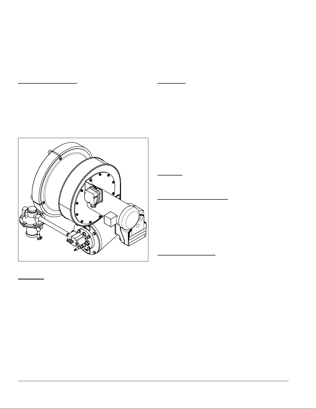
The ImmersoJet burner is a nozzle-mix, tube-firing burner
that is designed to fire at high velocities through small
diameter immersion tubes. The standard burner includes
a packaged blower, actuator control motor, integral
butterfly valve, ratio regulator, burner body, combustion
chamber, nozzle (specific to fuel used), rear cover, spark
and flame rods, and gas orifice (also specific to fuel used).
Figure 1.1. Standard ImmersoJet Burner
Features
Audience
This manual has been written for personnel already
familiar with all aspects of an immersion burner and its
add-on components, also referred to as the burner
system.
These aspects include:
• Design/selection
• Use
• Maintenance
The audience is expected to be qualified and have
experience with this type of equipment and its working
environment.
Purpose
The purpose of this manual is to ensure that the design of
a safe, effective, and trouble-free system is carried out.
ImmersoJet Documents
Design Guide No. 330
• This document
Datasheet Series No. 330
• Required to complete design and selection
Installation Guide No. 330
• Used with datasheet to complete installation
Related Documents
• EFE 825 (Combustion Engineering Guide)
• Eclipse Bulletins and Information Guides: 610, 710,
720, 730, 744, 760, 930
The combustion gases from the burner scrub the inner
tube surface and produce high heat transfer rates. This, in
combination with the high velocity flow through the smaller
diameter tubess allows for system efficiencies in excess
of 80%.
The smaller ImmersoJet tubes also have smaller bends
which means less tank space is occupied by the tubes.
With a combustion chamber that is integral to the burner
body, the new version of the ImmersoJet can sit lower on
the tank than previous ImmersoJet models.
4
32-00069—01
Page 5
Safety
DANGER
WARNING
NOTICE
Important notices which help provide safe burner
operation will be found in this section. To avoid personal
injury and damage to the property or facility, the following
warnings must be observed. All involved personnel should
read this entire manual carefully before attempting to start
or operate this system. If any part of the information in this
manual is not understood, contact Eclipse before
continuing.
2
■ This manual gives information for the use of these
burners for their specific design purpose. Do not
deviate from any instructions or application limits
in this manual without written advice from Eclipse.
Safety Warnings
■ The burners covered in this manual are designed
to mix fuel with air and burn the resulting mixture.
All fuel burning devices are capable of producing
fires and explosions when improperly applied,
installed, adjusted, controlled or maintained.
■ Do not bypass any safety feature; fire or explosion
could result.
■ Never try to light the burner if it shows signs of
damage or malfunction.
■ The burner is likely to have HOT surfaces. Always
wear protective clothing when approaching the
burner.
■ Eclipse products are designed to minimize the use
of materials that contain crystalline silica.
Examples of these chemicals are: respirable
crystalline silica from bricks, cement or other
masonry products and respirable refractory
ceramic fibers from insulating blankets, boards, or
gaskets. Despite these efforts, dust created by
sanding, sawing, grinding, cutting and other
construction activities could release crystalline
silica. Crystalline silica is known to cause cancer,
and health risks from the exposure to these
chemicals vary depending on the frequency and
length of exposure to these chemicals. To reduce
the risk, limit exposure to these chemicals, work in
a well-ventilated area and wear approved personal
protective safety equipment for these chemicals.
Capabilities
Only qualified personnel, with good mechanical aptitude
and experience with combustion equipment, should
adjust, maintain, or troubleshoot any mechanical or
electrical part of this system.
Operator Training
The best safety precaution is an alert and trained
operator. Train new operators thoroughly and have them
demonstrate an adequate understanding of the
equipment and its operation. A regular retraining schedule
should be administered to ensure operators maintain a
high degree of proficiency.
Replacement Parts
Order replacement parts from Eclipse only. Any customersupplied valves or switches should carry UL, FM, CSA,
CGA and/or CE approval where applicable.
32-00069—01
5
Page 6

System Design
3
Design
The design process is divided into the following steps:
1. Burner Model Selection
• Determine net input required for the tank or process
• Select tube efficiency
• Calculate gross input required
• Select burner model
2. Tube Design
3. Control Methodology
4. Ignition System
5. Flame Monitoring System
6. Combustion Air System: blower and air pressure
switch
7. Main Gas Shut-Off Valve Train
8. Process Temperature Control System
Step 1: Burner Model Selection
Determine the Net Input Required to the Tank
The net input to the tank is determined from heat balance
calculations. These calculations are based on the heatup
and steady-state requirements of the process, and take
into account surface losses, tank wall losses and tank
heat storage. Detailed guidelines for heat balance
calculations are in the Eclipse Combustion Engineering
Guide (EFE 825).
Select Tube Efficiency
The efficiency of the tube is the net heat input to the tank
divided by the heat input to the tube. Efficiency is
determined by the effective tube length. The diameter of
the tube has little influence on the efficiency. At a given
burner input, the net input to the tank is higher for a longer
tube than for a relatively short tube.
It is customary to size conventional immersion tubes for
70% efficiency, a reasonable compromise between fuel
economy and tube length. Small diameter tubes occupy
less tank space than conventional tubes, however, so
their length can easily be increased to provide efficiencies
of 80% or more.
Calculate the Gross Burner Input
Use this formula to calculate gross burner input in Btu/h:
net output to tank
tube efficiency
Fuel Type
Table 3.1 Fuel Type
Fuel Symbol
Natural
Gas
Propane C3H
Butane C4H
Btu/ft3 at standard conditions (MJ/m3 at normal
conditions)
If using an alternative fuel supply, contact Eclipse with an
accurate breakdown of the fuel components.
Applications Requiring Special Consideration
ImmersoJet burners are used for firing spray wash tanks,
dip tanks, and storage tanks such as those used for fire
sprinkler systems. Generally, the small bore system can
be used wherever conventional immersion burner
systems are used, except where high heat flux off the
small bore tube can break down the contents of the tank.
Zinc Phosphate Solutions
High heat fluxes break down the phosphate, forming a
heavy insulating sludge, which deposits on tube surfaces
and causes rapid tube burnout. To reduce early tube
failure, make the immersion tube with electro-polished
stainless steel, and limit the burner to the capacity shown
in the limited capacity portion of Table 3.2 where capacity
is based on tube size.
CH
90%+
4
Heating Value
1000 Btu/ft
(40.1 MJ/m
2525 Btu/ft3
8
(101.2 MJ/m
3330 Btu/ft3
10
(133.7 MJ/m
= gross burner input
Gross
3
3
)
3
3
Specific
Gravity
)
)
0.60
1.55
2.09
WOBBE
Index
1290
3
Btu/ft
2028
3
Btu/ft
2303
3
Btu/ft
6
32-00069—01
Page 7

Iron Phosphate Solutions
CAUTION
Highly Viscous Liquids
These are susceptible to the same problem described
above for zinc phosphate solutions. To reduce early tube
failure, make the immersion tube with stainless steel.
Electro-polishing is not required. Limit the burner to the
capacity shown in the limited capacity portion of Table 3.2
where capacity is based on tube size.
Cooking Oils
To avoid burning the oil, limit heat flux to 50 Btu/h per in
of the tube area.
Table 3.2 Capacity Guide
Tube
Model
IJ-2 2 (50) 190,000 (55) 235,000 (69) 370,000 (108) 110,000 (32) 220,000 (64)
IJ-3 3 (80) 440,000 (129) 550,000 (161) 850,000 (249) 250,000 (73) 500,000 (146)
IJ-4 4 (100) 800,000 (234) 1,000,000 (293) 1,800,000 (527) 440,000 (129) 880,000 (258)
IJ-6 6 (150) 2,000,000 (586) 2,400,000 (703) 3,600,000 (1054) 1,000,000 (293) 2,000,000 (586)
IJ-8 8 (200) 3,200,000 (938) N/A 4,700,000 (1377) 1,800,000 (527) 3,600,000 (1055)
Si ze,
in (mm)
Low-Pressure
Packaged
Bl ow er,
Btu/h (kW)
High-Pressure
Packaged
Bl ow er,
Btu/h (kW)
All immersion systems depend on natural convection
currents to carry heat away from the tube and throughout
the tank. Convection is minimal in high viscosity solutions
such as asphalt, residual oil or molasses. This can
severely overheat the liquid around the tube.
2
■ Do not use the ImmersoJet for highly viscous
fluids.
Select Burner Model
Choose a burner model with a maximum capacity greater
than the gross burner input calculated previously. Refer to
Table 3.2.
Remote Blower,
Btu/h (kW)
Limited Capacity
Zinc Phospate,
Btu/h (kW)
Limited Capacity
Iron Phospate,
Btu/h (kW)
Step 2: Tube Design
Determine Effective Tube Length
Find the required effective tube length using the
previously selected tube efficiency, net heat input values,
and Figures 3.1 or 3.2. The effective length of a tube is the
total centerline length of the tube covered by liquid.
32-00069—01
7
Page 8
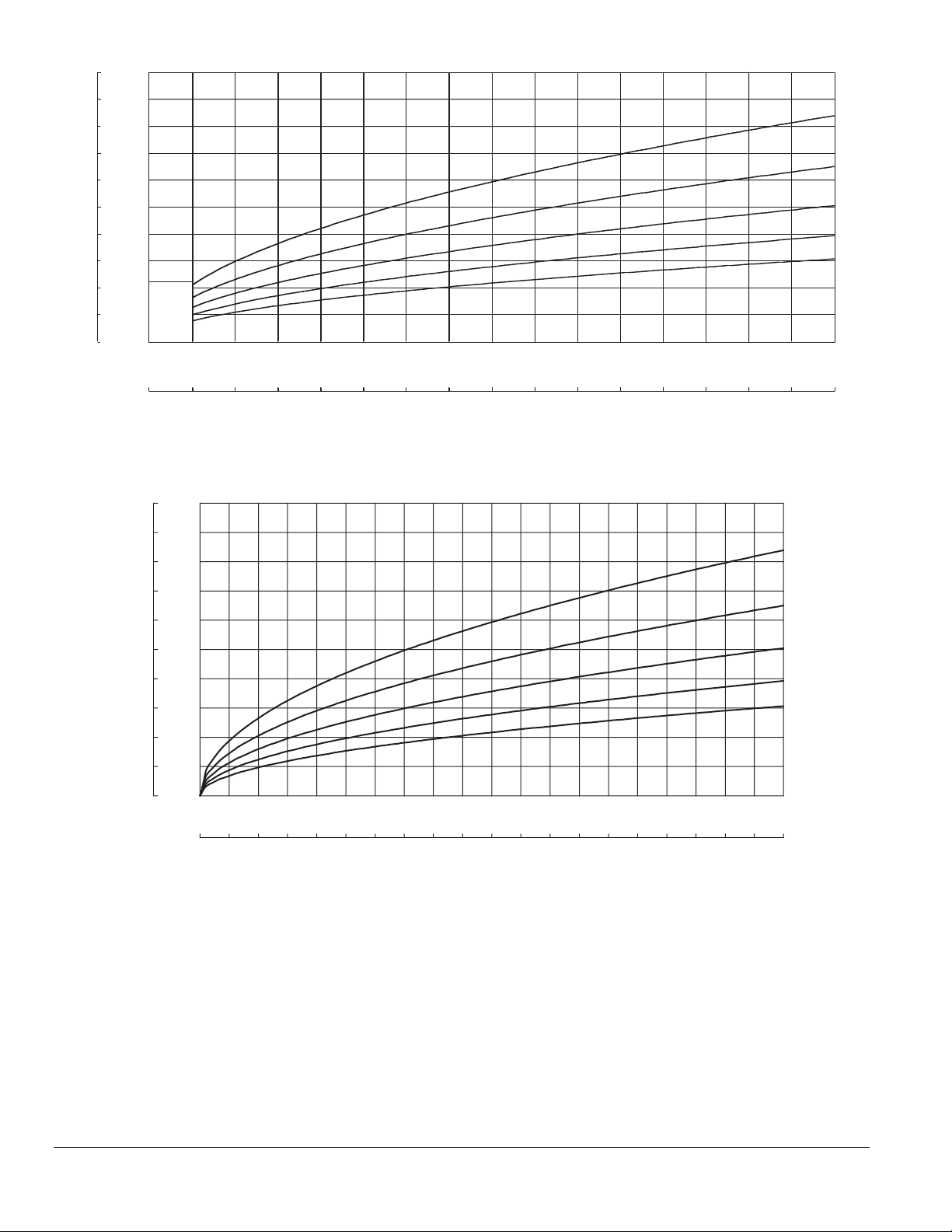
Figure 3.1. Effective Tube Length to 200 ft.
6,500 7,000 7,500 8,000
70%
65%
75%
80%
85%
200
0
20
40
60
80
100
120
140
160
180
Effective Tube Length, in Feet
61
0
6
12
18
24
31
37
43
49
55
Effective Tube Length, in Meters
500 1,000 1,500 2,000 2,500 3,000 3,500 4,000 4,500 5,000 5,500 6,000
Heat Transfer To Tank, Btu/h (x 1000)
0
1,903 2,050 2,196 2,343146 293 439 586 732 878 1,025 1,171 1,318 1,464 1,611 1,757
Heat Transfer To Tank, kW
0
See area
enlarged
below
50
45
40
35
30
25
20
15
10
Effective Tube Length, in Feet
5
0
0 50 100 150 200 250 300 350 400 450 500
0 15 30 45 60 75 90 105 120 135 150
Elbows
15.0
13.5
12.0
10.5
9.0
7.5
6.0
4.5
3.0
Effective Tube Length, in Meters
1.5
0.0
• Use standard and sweep elbows only.
• For optimal burner operation and maximum tube life
place the first elbow eight tube diameters from the
burner.
Stack
• Make sure that the stack is large enough to handle
the heated exhaust flow plus the dilution air.
8
Heat Transfer To Tank, Btu/h (x 1000)
Heat Transfer To Tank, kW
Figure 3.2. Effective Tube Length to 50 ft.
• The stack must be at least one pipe size larger than
the tube exhaust.
NOTE: If you use a common stack for more than one
burner, then make sure that the stack is large enough to
handle the exhaust flow plus any dilution air from all the
burners. Detailed guidelines for flue sizing calculations
are in the Eclipse Combustion Engineering Guide
(EFE 825).
85%
80%
75%
70%
65%
32-00069—01
Page 9
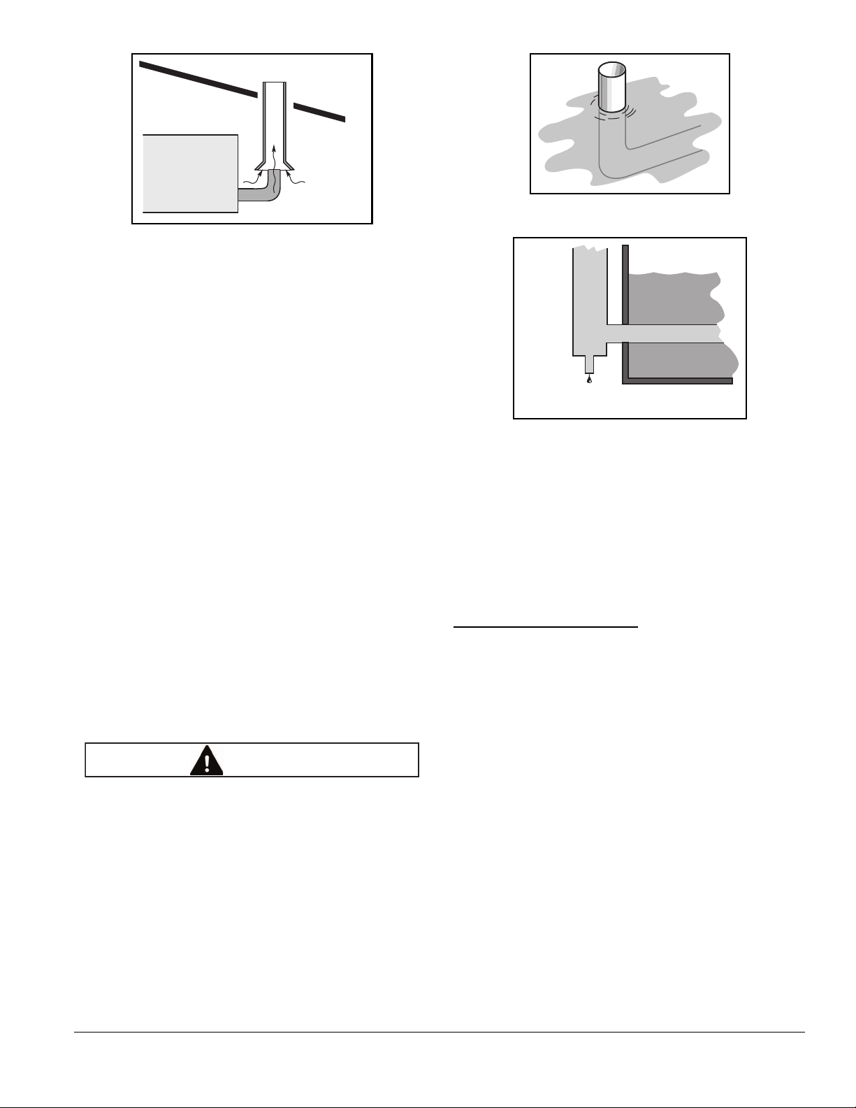
Figure 3.3.
Stack
Draft Breaking
Hood
Dilution Air
Tube Exhaust
CAUTION
Stack Twice
Tube
Diameter
1/2 inch
Drain
Pipe
Draft Breaking Hood
A draft breaking hood is an open connection between the
heater tube exhaust and the exhaust stack. It allows fresh
dilution air to pass into the exhaust and mix with the
exhaust gases.
The advantages of a draft hood are:
• the burner operation is less sensitive to atmospheric
conditions.
• the temperature of the exhaust gases is lower when
they pass through the roof.
NOTE: Leave access between the draft hood and the tube
exhaust. Install a damper plate if acoustic feedback
occurs in the tube.
Condensate provisions
If the immersion tube will operate at efficiencies less than
80%, the exhaust leg can be raised through the liquid
surface. For efficiencies of 80% or higher, locate the
exhaust stack outside of the tank and provide a drain. See
Figures 3.4 and 3.5.
Figure 3.4. Efficiencies less than 80%
Figure 3.5. Efficiencies 80% or more
Tube placement in tank
The tube placement height in the tank should be high
enough to avoid the possibility of sludge build-up on the
bottom of the tank; however, it should be low enough to
avoid tube exposure due to liquid level variations caused
by evaporation or displacement. In the latter case use a
liquid level switch to shut down the burner
Step 3: Control System
Control Methodology
NOTE: Regardless of the exhaust design, pitch the
immersion tube down towards the exhaust so condensate
will not collect at the burner.
■ At efficiencies of 80% or greater, low exhaust
temperatures will cause condensation to form in
the tube at start-up or during long idling periods.
The higher the efficiency the more condensation
will increase.
■ To prevent condensation/corrosion from
shortening tube life or disrupting burner
operation, provide a condensate drain at the
exhaust and slope the immersion tube downward,
away from the burner.
32-00069—01
ImmersoJet burners use a modulating on-ratio control
system as shown in Figure 3.3. To control the heat
delivered by the burner, adjust the air flow to the burner.
The gas flow will change in proportion to the air flow.
The burner will operate reliably at any input between the
low fire and high fire limits stated on the burner‘s
datasheet.
9
Page 10
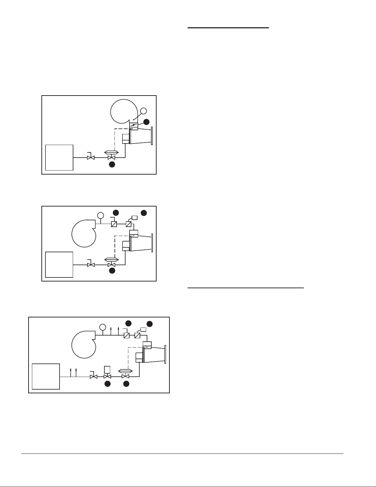
Components
P
1
2
Main Gas
Shut-Off
Valve Train
Loading
Line
Automatic butterfly valve
Ratio regulator: varies gas flow to burner in
proportion to air flow.
Automatic shut-off valve (optional).
Manual butterfly valve
Main Gas
Shut-Off
Valve Train
Figure 3.6. Packaged Blower
4
P
Loading
Line
2
Step 4: Ignition System
For the ignition system you should use:
• 6000 VAC transformers
• full wave spark transformers
• one transformer per burner
Do not use:
• 10,000 VAC transformers
• twin outlet transformers
• distributor type transformers
• half wave spark transformers
ImmersoJet burners will ignite reliably at any input within
the ignition zone shown in the appropriate burner
datasheet, however, it is recommended that low fire start
be used. Local safety and insurance requirements
demand that you limit the maximum time that a burner
takes to ignite. These time limits vary from country to
country.
The time that a burner takes to ignite depends on:
• the distance between the gas shut-off valve and the
burner
• the air/gas ratio
1
• the gas flow at start conditions.
In the USA, with a time of 15 seconds to ignition, there
should be sufficient time to ignite the burners. It is
possible, however, to have the low fire too low to ignite
within the time limit. Under these circumstances you must
consider the following options:
• start at higher input levels
• resize and/or relocate the gas controls
F i g ur e 3 . 7 . R e m ot e B lo w e r w it h E xt e r na l
Air Butterfly Valve
Main Gas
Shut-Off
Valve Train
to other burners
P
4
Loading
Line
23
1
Figure 3.8. Remote Blower with External Air Butterfly
Valve for Multiple Burner Zones
10
Step 5: Flame Monitoring System
A flame monitoring system consists of two main
parts:
• a flame sensor
• flame monitoring control
Flame sensor
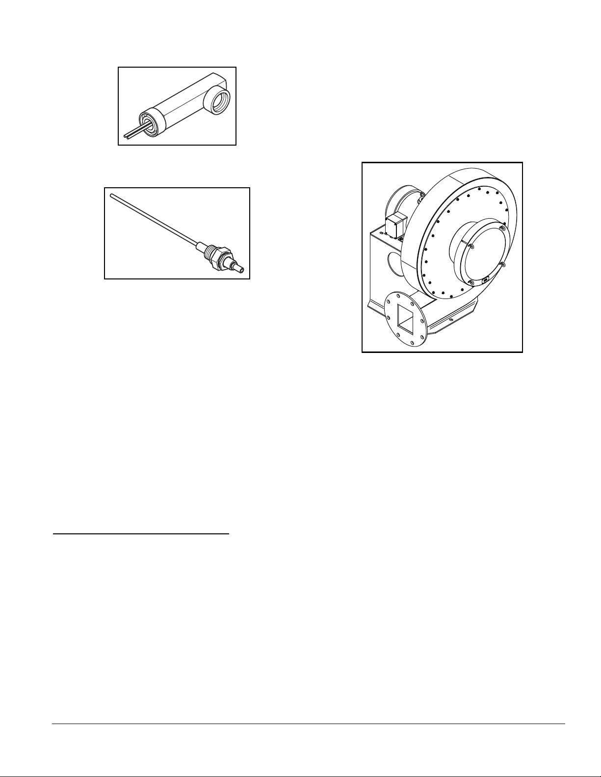
There are two types that you can use for an ImmersoJet
burner:
• U.V. scanner
• flame rod
You can find U.V. scanner information in:
• Info Guide 852; 90º U.V. scanner
• Info Guide 854; straight U.V. scanner
• Info Guide 855; Solid State U.V.I.R. scanner
• Info Guide 856; self-check U.V. scanner.
32-00069—01
Page 11
You can find flame rod information in Bulletin 832 and
Information Guide 832.
Figure 3.9. UV Scanner
Figure 3.10. Flame Rod
Flame Monitoring Control
• 29.92” Hg (1,013 mbar)
• 70ºF (21ºC)
The make-up of the air is different above sea level or in a
hot area. The density of the air decreases, and as a result,
the outlet pressure and the flow of the blower decrease.
An accurate description of these effects is in the Eclipse
Combustion Engineering Guide (EFE 825). The Guide
contains tables to calculate the effect of pressure, altitude
and temperature on air.
The flame monitoring control is the equipment that
processes the signal from the flame rod or the U.V.
scanner.
For flame monitoring control you may select several
options:
• flame monitoring control for each burner: if one
burner goes down, only that burner will be shut off
• multiple burner flame monitoring control: if one
burner goes down, all burners will be shut off
Other manufacturer’s flame monitoring systems can be
used with the burner if spark is maintained for a fixed time
interval and is not interrupted when a flame signal is
detected during trial for ignition
Step 6: Combustion Air System
ImmersoJet burners are sold in these configurations:
• Burner with integral low pressure blower.
• Burner with integral high pressure blower.
• Burner less blower.
NOTE: This section describes how to size a blower for
burners purchased without a blower.
Figure 3.11. SMJ Turbo Blower
Blower
The rating of the blower must match the system
requirements. You can find all the blower data in Bulletin
610.
Follow these steps:
1. Calculate the outlet pressure.
When calculating the outlet pressure of the
blower, the total of these pressures must be
calculated.
• the static air pressure required at the burner
• the total pressure drop in the piping
• the total of the pressure drops across the valves
• the pressure in the immersion tube
• recommend a minimum safety margin of 10%
2. Calculate the required flow
Effects of atmospheric conditions
The blower data is based on the International Standard
Atmosphere (ISA) at Mean Sea Level (MSL), which
means that it is valid for:
• sea level
32-00069—01
The blower output is the air flow delivered under standard
atmospheric conditions. It must be enough to feed all the
burners in the system at high fire.
11
Page 12

Combustion air blowers are normally rated in terms of
standard cubic feet per hour (scfh) of air.
An example calculation follows the information tables
below:
Required Calculation Information
Table 3.3 Fuel Type
Description
Unit of
Measure
Formula
Symbol
Total system heat input Btu/h Q
Number of burners - -
Type of fuel - -
Gross heating value of fuel Btu/ft
3
q
Desired excess air
percentage
(Typical excess air
percent %
percentage @ high fire is
15%)
Air/Gas ratio
(Fuel specific, see table
- α
below)
Air flow scfh V
Gas flow scfh V
air
gas
Btu/h) have sufficient capacity. For this
example, the designer selects the 4” tube
because his tank size limits the amount of the
larger 6” tube that will fit.
• Select an IJ004, 4” diameter tube ImmersoJet
burner with a remote blower for a maximum
firing rate of 1,225,000 Btu/h.
b. Calculate the required gas flow:
V
= Q/q = 1,225,000 Btu/h/1,002 Btu/ft
gas
3
=1,223 ft3/h
3
• Gas flow of 1,223 ft
/h is required.
c. Calculate the required stoichiometric air flow:
V
air-stoichiometric
= a (air/gas ratio) x V
gas
= 9.41 x 1,223 ft3/h = 11,508 ft3/h
• Stoichiometric air flow of 11,508 scfh required
d. Calculate the final blower air flow requirement
based on 15% excess air at high fire:
V
= (1 + excess air %) x V
air
air-stoichiometric
= ( 1 + 0.15) x 11,508 ft3/h = 13,234 ft3/h
• For this example, final blower air flow
requirement is 13,234 scfh at 15% excess air.
Fuel Gas Heating Values
Table 3.4 Fuel Type
Fuel Gas
Natural Gas
(Birmingham, AL)
Stoichiometric*
Air/Gas Ratio
3
air
/ft
3
gas
α (ft
9.41/1 1002
Gross Heating
)
q (Btu/ft
Value
3
)
Propane 23.82/1 2572
Butane 30.47/1 3225
*Stoichiometric: No excess air: The precise amount of air
and gas are present for complete combustion.
Application example:
A designer of a spray washer has determined the heat
input for the water tank requires 857,500 Btu/h. Based on
the size of his tank, he has selected a tube efficiency of
70% which results in a gross burner input of 1,225,000
Btu/h.
Calculation example to determine the air flow
requirement:
NOTE: It is common practice to add an additional 10% to
the final blower air flow requirement as a safety margin.
3. Find the blower model number and motor
horsepower (hp).
With the output pressure and the specific flow,
you can find the blower catalog number and the
motor hp in Bulletin 610.
4. Select the other parameters:
• inlet filter or inlet grille
• inlet size (frame size)
• voltage, number of phases, frequency
• blower outlet location, and rotation direction
Clockwise (CW) or Counter Clockwise (CCW
NOTE: The use of an inlet air filter is strongly
recommended. The system will perform longer and the
settings will be more stable.
a. Decide which ImmersoJet model is appropriate:
• From the capacity table, either the 4” with a
remote blower (1,800,000 Btu/h), or the 6” with
the low pressure packaged blower (2,000,000
12
32-00069—01
Page 13
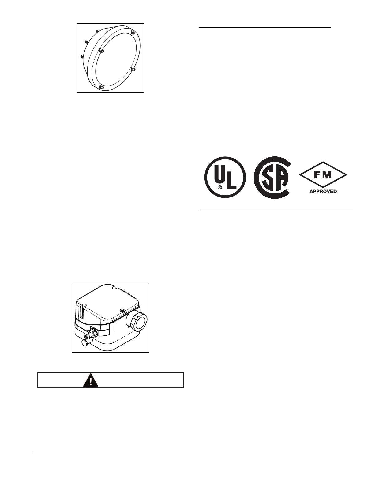
F i g u r e 3 . 1 2 . I n l e t f i l t e r
WARNING
with replaceable filter element
NOTE: When selecting a 60 Hz blower for use on 50 Hz,
a pressure and capacity calculation is required. See
Eclipse Combustion Engineering Guide (EFE 825).
The total selection information you should now have:
• blower model number
• motor hp
• motor enclosure (TEFC)
• voltage, number of phases, frequency
Step 7: Main Gas Shut-Off Valve Train
Consult Eclipse
Eclipse can help you design and obtain a main gas shutoff valve train that complies with the current safety
standards.
The shut-off valve train must comply with all the local
safety standards set by the authorities that have
jurisdiction.
For details, please contact your local Eclipse Combustion
representative or Eclipse Combustion.
NOTE: Eclipse Combustion supports NFPA regulations
(two shut-off valves) as a minimum standard for main gas
safety shut-off systems.
• rotation direction (CW or CCW).
Air pressure switch
The air pressure switch gives a signal to the monitoring
system when there is not enough air pressure from the
blower.
You can find more information on pressure switches in
Blower Bulletin 610.
Figure 3.13. Air Pressure Switch
Step 8: Process Temperature Control System
Consult Eclipse
The process temperature control system is used to control
and monitor the temperature of the system. There is a
wide variety of control and measuring equipment
available.
For details, please contact your local Eclipse Combustion
representative or Eclipse Combustion.
■ Eclipse Combustion supports NFPA regulations,
which require the use of an air pressure switch in
conjunction with other safety components, as a
minimum standard for main gas safety shut-off
systems.
32-00069—01
13
Page 14

Appendix
Conversion Factors
Metric to English
From To Multiply By
actual cubic meter/h (am³/h) actual cubic foot/h (acfh) 35.31
normal cubic meter/h (Nm³/h) standard cubic foot /h (scfh) 38.04
degrees Celsius (°C) degrees Fahrenheit (°F) (°C x 9/5) + 32
kilogram (kg) pound (lb) 2.205
kilowatt (kW) Btu/h 3415
meter (m) foot (ft) 3.281
millibar (mbar) inches water column ("w.c.) 0.402
millibar (mbar) pounds/sq in (psi)
millimeter (mm) inch (in) 3.94 x 10
MJ/Nm³ Btu/ft³ (standard) 26.86
Metric to Metric
14.5 x 10
-3
-2
English to Metric
actual cubic foot/h (acfh) actual cubic meter/h (am³/h) 2.832 x 10
standard cubic foot /h (scfh) normal cubic meter/h (Nm³/h) 2.629 x 10
degrees Fahrenheit (°F) degrees Celsius (°C) (°F - 32) x 5/9
inches water column ("w.c.) millibar (mbar) 2.489
From To Multiply By
kiloPascals (kPa) millibar (mbar) 10
meter (m) millimeter (mm) 1000
millibar (mbar) kiloPascals (kPa) 0.1
millimeter (mm) meter (m) 0.001
From To Multiply By
pound (lb) kilogram (kg) 0.454
Btu/h kilowatt (kW) 0.293 x 10
foot (ft) meter (m) 0.3048
pounds/sq in (psi) millibar (mbar) 68.95
inch (in) millimeter (mm) 25.4
Btu/ft³ (standard) MJ/Nm³ 37.2 x 10
-2
-2
-3
-3
32-00049—01
i
Page 15
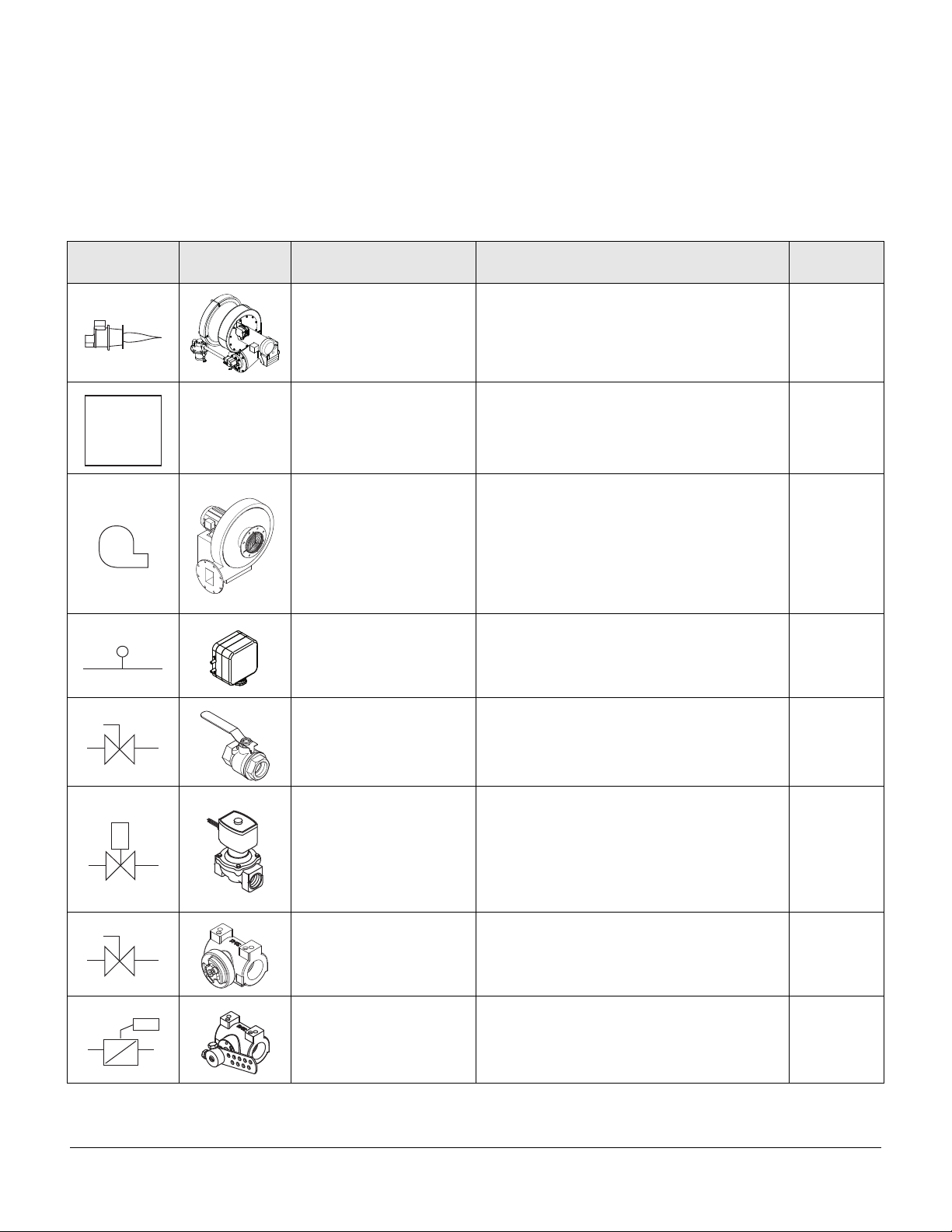
System Schematics
Symbol Appearance Name Remarks
Main Gas
Shut-Off
Valve
Train
P
NC
ImmersoJet burner
Bulletin/
Info Guide
Main Gas
Shut-Off
Valve Train
Combustion air blower
Pressure Switch
Gas Cock
Solenoid valve
(normally closed)
Eclipse Combustion, Inc. strongly endorses
NFPA as a minimum.
The combustion air blower provides the
combustion air to the burner(s).
A switch activated by rise or fall in pressure.
A manual reset version requires pushing a
button to transfer the contacts when the
pressure set point is satisfied.
Gas cocks are used to manually shut off the
gas supply.
Solenoid valves are used to automatically
shut off the gas supply on a bypass gas
system or on small capacity burner systems.
756
610
610
I-354
710
760
Manual Butterfly Valve
Automatic Butterfly Valve
32-00069—01
Manual butterfly valves are used to balance
the air or gas flow at each burner.
Automatic butterfly valves are typically used
to set the output of the system.
720
720
ii
Page 16
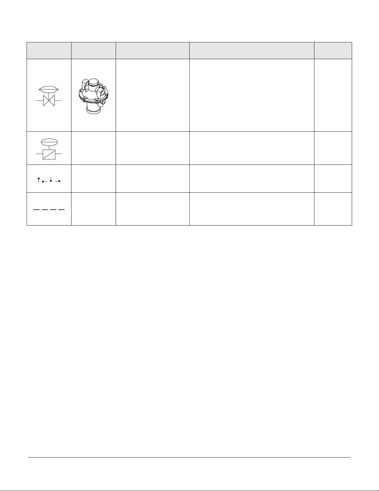
Symbol Appearance Name Remarks
A ratio regulator is used to control the air/gas
ratio. The ratio regulator is a sealed unit that
adjusts the gas flow in ratio with the air flow.
To do this, it measures the air pressure with a
Ratio Regulator
pressure sensing line, the impulse line. This
impulse line is connected between the top of
the ratio regulator and the air supply line.
The cap must stay on the ratio regulator after
adjustment.
A CRS valve is used in a high/low time-
CRS Valve
proportional control system to quickly open
and close the air supply.
Pressure taps measure static pressure.
Pressure Taps
The schematics show the advised positions
of the pressure taps.
Bulletin/
Info Guide
742
744
Impulse Line
The impulse line connects the ratios regulator
to the air supply line.
32-00069—01
iii
Page 17

© 2016 Honeywell International Inc. All rights reserved
 Loading...