

Page 1

1Overview
Figure 1 ECC-RPU
screw
location
Figure 2 Removing the Dress Panel
1. lift up
2. pull out
3. slide down
keyholes
10.0” (25.4cm) O.C.
lower mounting holes
Figure 3 Backbox Mounting
The ECC-RPU is an optional Remote Page Unit
compatible with the ECC-50/100 Emergency Command
Center. The ECC-RPU provides 8 message select buttons.
The 9th button can be used to activate an MMF-300
monitor module mounted inside the cabinet. The RPU
requires an external data bus connection, an external audio
riser connection, and an external operator interface power
connection (24 volts DC) from the ECC-50/100 main
console. ALL CALL paging can be broadcast over the
speaker circuits by depressing the microphone's push-totalk switch. Refer to the ECC-50/100 Manual, LS10001000FL-E, for more information.
One Fire-Lite Place
Northford, CT 06472-1653 USA
203-484-7161 • FAX 203-484-7118
www.firelite.com
ECC-RPU Remote Page Unit
Product Installation Document
PN LS10030-000FL-E:B 8/9/2013 13-696
2.2 Mounting the Backbox
1. Mark and predrill holes for the top two backbox
keyhole mounting bolts using the dimensions shown.
2. Install two upper fasteners in the wall with the screw
heads protruding.
3. Using the upper 'keyholes', mount the backbox over
the two screws.
4. Mark and drill the lower two holes.
5. Install the remaining fasteners and tighten all
fasteners to complete backbox mounting.
NOTE: Installation and wiring of this device must be
done in accordance with NFPA 72 and local ordinances.
2Installation
2.1 Removing the Dress Panel
1. Open the door and lift the door off the pin hinges.
2. Loosen the screw securing the dress panel to the
backbox.
3. Open dress panel and disconnect the ground wire
from the back.
4. Lift up dress panel and pull out lower pivot flange.
Slide the upper pivot flange down to completely
remove the dress panel from cabinet. Store in a safe
location.
6. Carefully reinstall the dress panel by reversing the
steps in Section 2.1. Remember to reattach the
ground cable.
7. Reinstall door.
A trim ring, TR-6-R, is available for semi-flush mount
installations.
Page 2
2.3 Mounting/Wiring an Optional Monitor Module
An MMF-300 monitor module may be mounted inside the
cabinet. This can be used for HVAC shutdown
applications when the monitor module is connected to the
FACP SLC polling loop. The monitor module is wired to
TB4 on the RPU and is activated by the 9th button on the
RPU keypad. The module’s LED is visible through the
keypad next to the 9th button.
1. Remove the two (2) keps nuts that secure the RPU
board to the dress panel using a 5/16” socket.
2. Set the SLC address on the MMF-300. Remove the
four (4) break-away tabs from the monitor module.
See Figure 4.
3. Insert the bottom of the monitor module (SLC address
dials facing inward) into the mounting tabs on the left
side of the RPU. The RPU mounting screws will go
through the top of the monitor module. Situate the
LED on the front of the module over the hole in the
PC board.
4. Replace the keps nuts over the mounting screws to
secure the monitor module to the board.
5. Connect the SLC wiring to the module terminals 1 (–)
and 2 (+). Refer to the SLC Wiring Manual for more
information.
6. Wire TB4 on the RPU to T6/T7 on the monitor
module as shown below. No ELR is required as it is
built into TB4.
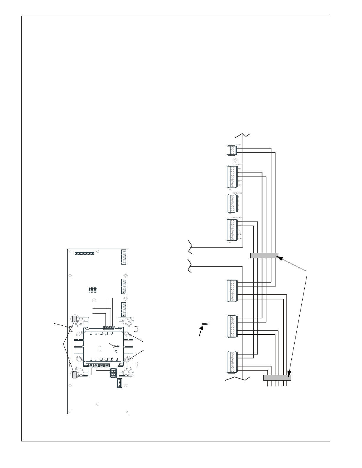
3 Wiring
Connections are made from TB24, TB12, and TB22 on the
ECC-50/100 main control board to TB1, TB3, and TB2 on
the RPU. If the ECC-RPU is the last device on the audio
and data bus chain, signal terminations are required. For
the last device on the external data bus, a removable
jumper must be on pins 1 and 2 of JS4. If the ECC-RPU is
not the last device, the jumper must be on pins 2 and 3 of
JS4 as shown below. For the external audio riser,
termination (15K ohm resistor) must be connected to pins
4 and 5 on TB2. A ferrite clamp (P/N: 50116546-001)
must be installed around all wires in both the input and
output wire runs
ECC main
control board
inside the RPU cabinet as shown below.
external operator interface
external
data bus
external
audio
riser
+
-
power - 24VDC
TB24
TB12
TB22
+
-
B
A
SLC Out
Remove
break-away
tabs (4) from
module
mounting
tabs
SLC In
+ -
LED on other
side of module
TB4
Figure 4 Wiring an MMF-300 to the RPU
keps
nuts
RPU board
24V
OUT
Data
JS4
(shown jumpered
on pins 2 and 3)
Audio
Figure 5 Remote Page Unit Wiring
TB1
+
1
-
IN
2
3
+
4
-
5
TB3
B
1
IN
A
2
3
B
4
OUT
OUT
A
5
TB2
+
1
IN
-
2
3
+
4
-
5
(Class B/Style Y)
ferrite clamp
to next operator interface/
amplifier or 15K ELR
(if last device)
2 ECC-RPU Installation Document — P/N LS10030-000FL-E:B 8/9/2013
Page 3

ECC main
control board
TB12
TB24
external operator interface
power - 24VDC
+-
external
data bus
B
A
B
A
5 Slide-in Label
Carefully cut along the outside of the label. Identify
keypad buttons as desired and slide the label upwards
through the slot at the bottom of the keypad.
TB22
RPU board
IN
24V
OUT
IN
Data
OUT
IN
Audio
OUT
TB1
1
2
3
4
5
TB3
1
2
3
4
5
TB2
1
2
3
4
5
+
-
B
A
B
A
+
-
+
-
external
audio
riser
+
-
+
-
ferrite clamp
OK TO PAGE
MIC TROUBLE
Figure 6 Remote Page Unit Wiring
(Class A/Style Z)
4 LED Indicators
OK to Page A green LED that turns on steady to
instruct the operator that he/she may start paging.
Mic Trouble A yellow LED that turns on steady to
indicate a microphone wiring fault.
Power A green LED that turns on steady when DC
power is present.
Data Bus Fault A yellow LED turns on steady when
the main console and RPU cannot communicate.
Audio Riser Fault A yellow LED that turns on steady
when the audio riser wiring is open or short-circuited.
Board Fault A yellow LED that turns on steady when a
critical issue has been detected with the board. There are
no serviceable parts. Contact service personnel to replace
the unit.
ECC-RPU Installation Document — P/N LS10030-000FL-E:B 8/9/2013 3
POWER
DATA BUS FAULT
AUDIO RISER FAULT
BOARD FAULT
 Loading...