

Page 1

1Overview
Figure 1 ECC-RM
screw holes
Figure 2 Microphone Assembly Screw locations
mounting slots
Figure 3 Removing the Microphone Assembly
The ECC-RM is an optional Remote Microphone
compatible with the ECC-50/100 Emergency Command
Center. ALL CALL paging can be broadcast over the
speaker circuits by depressing the microphone's push-totalk switch. The RM requires an external data bus
connection, an external audio riser connection, and an
external operator interface power connection (24 volts
DC) from the ECC-50/100 main console. Refer to the
ECC-50/100 Manual, LS10001-000FL-E, for more
information.
One Fire-Lite Place
Northford, CT 06472-1653 USA
203-484-7161 • FAX 203-484-7118
www.firelite.com
ECC-RM Remote Microphone
Product Installation Document
PN LS10029-000FL-E:B 8/27/2013 13-739
3. Remove the bracket/microphone by sliding the
assembly out of its mounting slots.
4. Store assembly in a safe location.
NOTE: Installation and wiring of this device must be
done in accordance with NFPA 72 and local ordinances.
2Installation
2.1 Removing the Bracket/
Microphone Assembly
1. Unlock the cabinet door.
2. Remove the two screws holding the assembly in
place.
2.2 Mounting the Backbox
1. Mark and predrill two holes for the top and two for
the bottom of the backbox.
2. Hold cabinet on wall and tighten down all fasteners to
complete backbox mounting.
Page 2
3. Carefully reinstall the bracket/microphone assembly.
mounting holes
4.0” (10.16cm) O.C.
lower mounting holes
Figure 4 Backbox Mounting
earth ground
+
-
+
-
+
-
+
-
B
A
A
B
+
-
+
-
A
B
5
4
3
2
1
5
4
3
2
1
5
4
3
2
1
main control board
RM board
TB24
TB12
TB22
external operator
interface power -
24VDC
external data bus
external
audio
riser
to next operator
interface or
amplifier
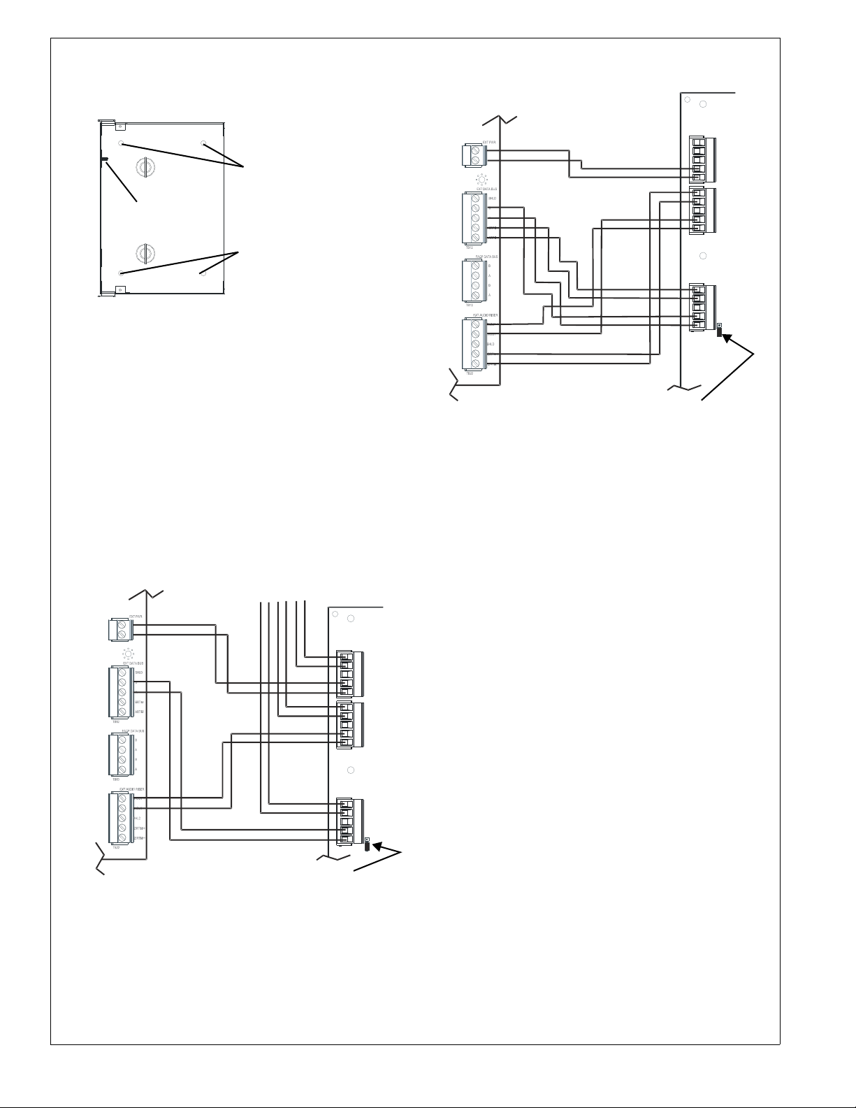
Figure 5 Remote Microphone Wiring
(Class B/Style Y)
JS4
(shown jumpered
on pins 2 and 3)
TB3
data
bus
TB2
audio
out
TB1
power
+
+
-
+
-
+
-
B
A
B
A
A
B
A
B
+
-
+
-
54321
543
2
15432
1
main control board
RM board
TB24
TB12
TB22
TB3
data
bus
TB2
audio
out
TB1
power
external operator
interface power -
24VDC
external
data
bus
external
audio
riser
Figure 6 Remote Microphone Wiring
(Class A/Style Z)
JS4
(shown jumpered
on pins 2 and 3)
Remember to attach the ground cable.
3 Wiring
Connections are made from TB24, TB12, and TB22 on the
ECC-50/100 main control board to TB3, TB2, and TB1 on
the RM. If the ECC-RM is the last device on the audio
and data bus chain, signal terminations are required. For
the external data bus, a removable jumper must be on pins
1 and 2 of JS4. If the ECC-RM is not the last device, the
jumper must be on pins 2 and 3 of JS4. For the external
audio riser, termination (15K ohm resistor) must be on
pins 4 and 5 on TB2.
4 LED Indicators
System in Use A green LED that turns on steady when
the main console, an LOC, an RPU, or an RM has control
of the audio system.
OK to Page A green LED that turns on steady to
instruct the operator that he/she may start speaking.
2 ECC-RM Installation Document — P/N LS10029-000FL-E:B 8/27/2013
Power A green LED that turns on steady when DC
power is present.
Data Trouble A yellow LED turns on steady when the
main console and RM cannot communicate.
Audio Trouble A yellow LED that turns on steady
when the audio riser wiring is open or short-circuited.
Mic Trouble A yellow LED that turns on steady to
indicate a microphone wiring fault.
 Loading...