

Page 1
1Overview
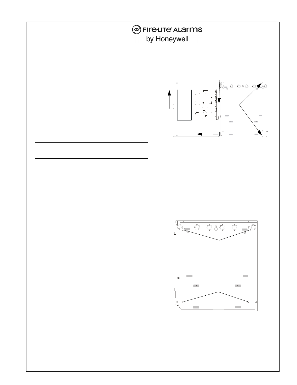
screw
locations
Figure 1 Removing the Dress Panel
1. lift up
2. pull out
3. slide down
keyholes
12.0” (30.48cm) O.C.
lower mounting holes
Figure 2 Backbox Mounting
The ECC-LOC is an optional Local Operator Console
compatible with the ECC-50/100 Emergency Command
Center. The ECC-LOC has a complete operator interface
like the ECC-50/100 main console. The LOC requires an
external data bus connection, an external audio riser
connection, and an external operator interface power
connection (24 volts DC) from the ECC-50/100 main
console. Refer to the ECC-50/100 Manual #LS10001000FL-E for more information.
One Fire-Lite Place
Northford, CT 06472-1653 USA
203-484-7161 • FAX 203-484-7118
www.firelite.com
ECC-LOC Local Operator Console
Product Installation Document
PN LS10028-000FL-E:B 8/9/2013 13-696
NOTE: Installation and wiring of this device must be
done in accordance with NFPA 72 and local ordinances.
2 Specifications
• Data Bus Input - TB3 - 1(B), 2(A) EIA-485 /
Data Bus Output - TB4 - 1(B), 2(A) EIA-485
• Operator Interface Power Input - TB3 - 3(+), 4 (-) /
Operator Interface Power Output - TB4 - 3(+), 4(-)
– 24 VDC Nominal, Isolated
• Audio Riser Input - TB5 - 3(-), 4(+) /
Audio Riser Output - TB5 - 5(-), 6(+)
– Style Y (Class B) or Style Z (Class A) audio
connections to external operator interface
components
– Power-limited circuitry (Class 2), supervised
– Audio signal level: 3.85 V
, maximum
RMS
– Frequency range: 800 Hz - 2800 Hz
3 Cabinet Mounting
3.1 Removing the Dress Panel
1. Open the door and lift the door off the pin hinges.
2. Remove the two (2) screws securing the dress panel to
the backbox.
3. Open the dress panel and disconnect the ground wire
from the back.
4. Lift up dress panel and pull out lower pivot flange.
Slide the upper pivot flange down to completely
remove the dress panel from cabinet. Store in a safe
location.
3.2 Mounting the Backbox
1. Mark and predrill hole in the wall for the center top
keyhole mounting bolt using the dimensions illustrated below.
2. Install center top fastener in the wall with the screw
head protruding.
3. Place backbox over the top screw, level and secure.
4. Mark and drill the left and right upper and lower
mounting holes.
Note: Outer holes (closest to sidewall) are used for
16” O.C. stud mounting.
5. Install remaining fasteners and tighten.
6. Carefully reinstall the dress panel by reversing the
steps in Section 3.1. Remember to reattach the
ground cable.
7. Reinstall door.
A trim ring, TR-CE, is available for semi-flush mount
installations.
Page 2
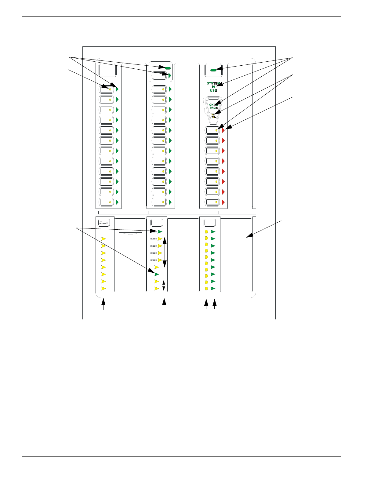
4Keypad
FIRE SYSTEM
ACTIVE
SYSTEM
CONTROL
ALL
CALL
1
2
3
4
5
6
7
8
9
10
11
12
13
18
19
20
21
22
23
24
16
17
14
15
Figure 3 ECC-LOC Keypad
ecckyd.wmf
SPEAKER
ZONE 1
SPEAKER
ZONE 2
SPEAKER
ZONE 3
SPEAKER
ZONE 4
SPEAKER
ZONE 5
SPEAKER
ZONE 6
SPEAKER
ZONE 7
SPEAKER
ZONE 8
SPEAKER
ZONE 9
SPEAKER
ZONE 10
SPEAKER
ZONE 11
SPEAKER
ZONE 12
SPEAKER
ZONE 13
SPEAKER
ZONE 14
SPEAKER
ZONE 15
SPEAKER
ZONE 16
SPEAKER
ZONE 17
SPEAKER
ZONE 18
SPEAKER
ZONE 19
SPEAKER
ZONE 20
SPEAKER
ZONE 21
SPEAKER
ZONE 22
SPEAKER
ZONE 23
SPEAKER
ZONE 24
MESSAGE 1
MESSAGE 2
MESSAGE 3
MESSAGE 4
MESSAGE 5
MESSAGE 6
MESSAGE 7
MESSAGE 8
DIST. AMP 1
DIST. AMP 2
DIST. AMP 3
DIST. AMP 4
DIST. AMP 5
DIST. AMP 6
DIST. AMP 7
DIST. AMP 8
DIAGNOSTIC
REMOTE AMPS
TROUBLE SILENCE
AC POWER
GROUND FAULT
CHARGER FAULT
BATTERY FAULT
DATA BUS FAULT
NAC FAULT
NAC ACTIVE
SYSTEM TROUBLE
AUDIO RISER FAULT
LOC 1
LOC 2
RPU 1
RPU 2
RPU 3
RM 1
RM 2
RM 3
CONSOLE LAMP TEST
MAIN CONSOLE
MNS
CONTROL
OK TO PAGE
MICROPHONE
TROUBLE
green green
yellow
yellow
red
green
green
yellow
Note: Console
assignments are
shown here as an
example only.
4.1 Switch Functions
All Call Activates all speaker circuits for broadcast.
MNS Control (for systems configured for mass
notification operation which has higher priority)
Activates the MNS Active Relay and the onboard NAC. A
second press turns these back off. For a combination fire
and mass notification system, pressing MNS C
will result in the shutdown of audible FACP NACs and
audio system speakers, allowing the system to override the
system. Pressing MNS C
to re-activate audible FACP NACs and audio system
speakers.
ONTROL again causes the FACP
ONTROL
System Control Manually gains control of the audio
system in preparation for an ALL CALL, message
activation, or general page. The green LED will turn on
steadily to confirm control. A second press is required
after paging to relinquish control of the system. The main
console will have system priority based upon user
programming. In order for the LOC to gain control, the
ECC must first relinquish control of the system.
Speaker Select 1-24 Manually activates or deactivates
speaker zones (circuits).
Message Select 1-8 Manually activates or deactivates
stored messages. 8th button becomes a “shift” for
messages 9-14.
2 ECC-LOC Installation Document — P/N LS10028-000FL-E:B 8/9/2013
Page 3

Diagnostic Select selects a specific remote amplifier
to examine specific trouble conditions for the remote
amplifiers. The fault LEDs with wrench graphics represent
the amplifier selected.
Trouble Silence Manually silences the local trouble
sounder.
Console Lamp Test Tests the local LEDs and sounder.
4.2 LED Indicators
Fire System Active Green LED that turns on steady
when the FACP is in alarm.
MNS Control Green LED that turns on steady when an
operator has initiated a mass notification event by pressing
the MNS Control button or by pressing an MNS message
button.
System Control Green LED that turns on steady when
the main console has control of the audio system.
System in Use Green LED text that turns on steady
when the main console, an LOC, an RPU, or an RM has
control of the audio system.
Speaker Zones 1-24 Green LED per speaker circuit
button that turns on steady when a speaker circuit has been
selected and is active. Yellow LED per speaker circuit
button that turns on steady when a speaker circuit fault
exists or when the speaker circuit has been turned off after
having been automatically turned on by the FACP.
OK to Page Green LED text that turns on steady when
the system is ready for paging.
Microphone Trouble Yellow LED text that turns on
steady to indicate a microphone wiring fault.
Messages 1-8 Red LED per message button that turns
on steady when the message has been selected and blinks
when the message has been overridden. Yellow LED per
message button that turns on steady when no message has
been recorded or there is an associated command input
fault. All eight message button LEDs will turn on steady to
indicate a message generator fault. 8th button “shift” key
red off when viewing messages 1-7 and on steady when
viewing messages 8-14. Yellow LED will turn on
indicating a message trouble in the group of messages not
currently being viewed.
Main Console Fault Yellow LED that turns on steady
when the main (or primary operator) console has a fault.
AC Power Green LED that turns on steady when AC
power is present.
Ground Fault Yellow LED that turns on steady when a
ground fault exists in the system.
Charger Fault Yellow LED turns on steady when the
battery charger voltage is too high or low.
Battery Fault Yellow LED turns on steady when battery
voltage is too low.
Data Bus Fault Yellow LED that turns on steady when
the main and remote console(s) cannot communicate.
NAC Fault Yellow LED that turns on steady when the
onboard NAC wiring is open or short-circuited.
NAC Active Green LED that turns on steady when the
NAC output is on.
System Trouble Yellow LED that turns on steady when
any fault exists in the system.
Audio Riser Fault Yellow LED that turns on steady
when the audio riser wiring is open or short-circuited.
5 Wiring
Wiring for the Local Operator Console is accomplished
between TB24, TB12, and TB22 on the ECC-50/100 main
control board to TB3, TB4, and TB5 on the LOC. If the
ECC-LOC is the last device on the audio and data bus
chain, signal terminations are required. For the external
data bus, a removable jumper must be on pins 1 and 2 of
JP2. If the ECC-LOC is not the last device, the jumper
must be on pins 2 and 3 of JP2 as shown below. For the
external audio riser, termination (15K ohm resistor) must
be connected to pins 5 and 6 on TB5. A ferrite clamp
(P/N: 50116546-001) must be installed around all wires in
both the input and output wire runs inside the ECC-LOC
cabinet as shown below. Refer to the ECC-50/100 Manual
#LS10001-000FL-E for more information.
Remote Amplifiers 1-8 Fault Yellow LED per remote
amplifier that turns on steady when an amplifier has a
fault.
LOC/RPU/RM 1-8 Fault Yellow LED per remote
console that turns on steady when a remote console has a
fault. Green LED per remote console that turns on steady
when a remote console is active.
ECC-LOC Installation Document — P/N LS10028-000FL-E:B 8/9/2013 3
Page 4

B
A
+
-
-
+
-
+
B
A
+
-
+
-
+
-
B
A
B
A
main control
board
LOC display board
TB24
TB12
TB22
TB3
TB4
TB5
external operator interface
power - 24VDC
external data bus
external audio riser
to next operator interface or amplifier (or, if
last device, signal termination ELR-15K)
to next
operator
interface or
amplifier
Figure 4 Local Operator Console Wiring
(Class B/Style Y)
TB2
JP2
(shown jumpered
on pins 2 and 3)
All wiring shown is
power-limited (Class 2).
ferrite clamp
B
A
+
-
-
+
-
+
B
A
+
-
+
-
+
-
B
A
B
A
+
-
main control
board
LOC display board
TB24
TB12
TB22
TB3
TB4
TB5
external operator interface power - 24VDC
external data bus
external audio riser
Figure 5 Local Operator Console Wiring
(Class A/Style Z)
TB2
All wiring shown is
power-limited (Class 2).
ferrite clamp
6 Operating Instructions
Normal Standby Operation
1. Green AC P
2. Yellow T
3. Green speaker zone indicators off.
Alarm Condition
1. Green speaker zone indicator(s) lit steadily.
2. Green S
3. Audio message plays.
4. Green F
(when FACP is in alarm).
5. Green MNS C
activated (for mass notification events).
4 ECC-LOC Installation Document — P/N LS10028-000FL-E:B 8/9/2013
OWER indicator lit steadily.
ROUBLE indicators off.
YSTEM IN USE indicator lit steadily.
IRE SYSTEM ACTIVE indicator lit steadily
ONTROL indicator lit steadily and relay
Alarm Reset After locating and correcting a fire alarm
condition at the FACP, the system will return to Normal
Standby Operation. After correcting a mass notification
event, press the MNS C
ONTROL button to clear the system
and return to Normal Standby Operation.
Trouble Condition Activation of trouble signal under
normal operation indicates a condition that requires
immediate attention. Contact your local service
representative. Silence the audible signal by pressing the
T
ROUBLE SILENCE switch. The trouble indicator will
remain illuminated.
 Loading...