

Honeywell EASTOVER 10214 Owner's Manual
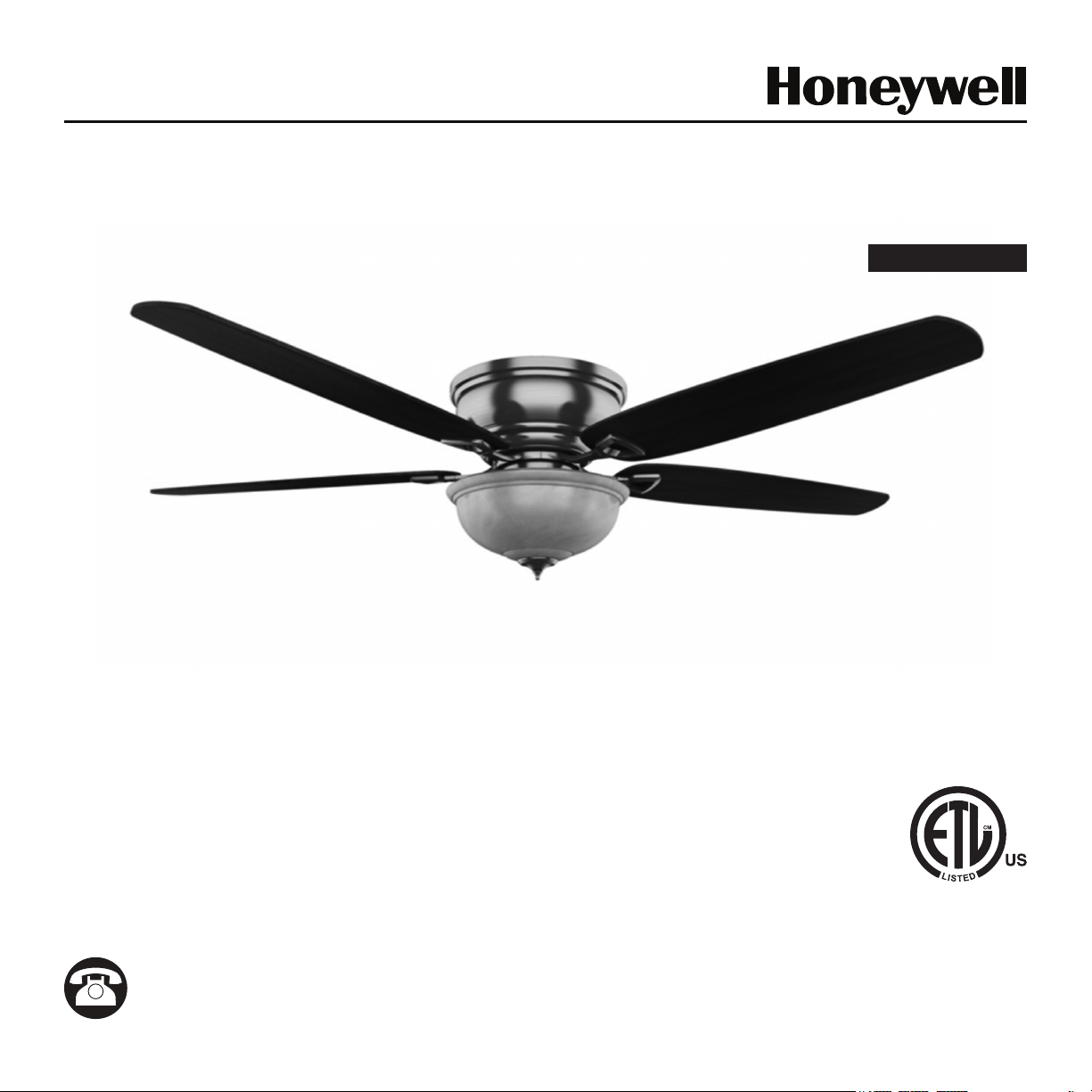
EASTOVER 52” CEILING FAN
MODEL #10214
Español p. 17
Questions, problems, missing parts? Before returning to your retailer, call our customer
service department at 1-877-361-3883, Monday - Thursday, 8 am - 6 pm, EST and Friday,
8 am - 5 pm, EST.

WELCOME
TABLE OF CONTENTS
Care and Maintenance ........................2
Package Contents ...........................3
Safety Information ...........................4
Mounting Bracket Installation ...................5
Hanging Your Fan............................6
Wiring .....................................7
Motor Housing Installation .....................8
Blade Installation ............................9
Light Kit Installation .........................10
Final Installation . . . . . . . . . . . . . . . . . . . . . . . . . . . .12
Operating Installation . . . . . . . . . . . . . . . . . . . . . . . .13
Replacement Parts List ......................14
Troubleshooting ............................15
Limited Lifetime Warranty.....................16
PREPARATION
Before beginning the assembly of this product, ensure
that all parts are present. Compare all parts with the
package contents list and hardware contents list. If
any part is missing or damaged, do not attempt to
assemble the product.
After opening the top of the carton, remove the
mounting hardware package from the foam inserts,
then remove the motor from the packaging and
place it on a soft surface, such as a carpet, to avoid
damage to the nish.
Estimated Assembly Time: Under 60 minutes
Tools Required for Assembly (not included): Electrical
Tape, Phillips Screwdriver, Pliers, Safety Glasses,
Step Ladder, and Wire Strippers
Helpful Tools (not included): AC Tester Light, Tape
Measure, Wiring Handbook, and Wire Cutters
CARE AND MAINTENANCE
ATTACH YOUR RECEIPT HERE
Serial Number
Purchase Date
At least twice each year, lower the canopy to check
the downrod assembly, and then tighten all screws
on the fan. Clean the motor housing with only a soft
brush or lint-free cloth to avoid scratching the nish.
Clean the blades with a lint-free cloth. You may
occasionally apply a light coat of furniture polish to
wood blades for added protection.
Important: Shut o the main power supply before you
begin any maintenance tasks. Do not use water or a
damp cloth to clean the ceiling fan.
FAN WEIGHT
The net weight of this fan is: 16.28 lbs. (7,38 kg).
2
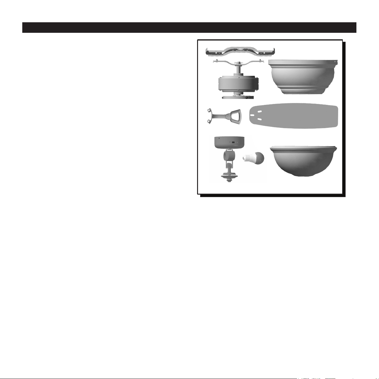
PACKAGE CONTENTS
Unpack your fan and check the contents. You should
have the following items:
1. Upper Mounting Bracket
2. Motor with Lower Mounting Bracket
3. Blade Arm (5)
4. Switch Housing
5. Light Kit
6. Motor Housing
7. Blade (5)
8. E26-base LED Bulbs (2)
9.Glass Bowl
10. Finial Cap
11. Finial
12. Loose parts bags containing (not shown):
Mounting hardware, electrical hardware, pull
chains, wire connectors, etc.
13. Owner’s Manual (not shown)
1
6
2
3
7
4
5
8
10
11
9
3
SAFETY INFORMATION
Please read and understand this entire manual before attempting to assemble, operate, or install the product.
• Before you begin installing the fan, disconnect the power by removing fuses or turning off the
circuit breakers.
• Make sure that all electrical connections comply with local codes, ordinances, the National Electrical
Code, and ANSI/NFPA 70-199. Hire a qualied electrician or consult a do-it-yourself wiring handbook if
you are unfamiliar with installing electrical wiring.
• Make sure the installation site you choose allows a minimum clearance of 7 ft. (2,14 m) from the blades
to the oor and at least 30 in. (76 cm) from the end of the blades to any obstruction.
DANGER
! !
When using an existing outlet box, make sure
the outlet box is securely attached to the building
structure and can support the full weight of
the fan. Failure to do this can result in serious
injury or death. The stability of the outlet box is
essential in minimizing wobble and noise in the
fan after installation is complete.
WARNING
!
To reduce the risk of re or electric shock, do not
use the fan with any solid-state speed-control
device or control the fan speed with a full-range
dimmer switch.
WARNING
!
To reduce the risk of re, electric shock, or
personal injury, do not bend the blade arms
when installing them, balancing the blades, or
cleaning the fan. Do not insert objects between
the rotating fan blades.
! !
!
!
WARNING
To reduce the risk of re, electric shock, or personal
injury, mount the fan to an outlet box marked
“ACCEPTABLE FOR FAN SUPPORT” and use the
mounting screws provided with the outlet box. Most
outlet boxes commonly used for the support of
lighting xtures are not acceptable for fan support
and may need to be replaced. Consult a qualied
electrician if in doubt. Secure the outlet box directly
to the building structure. The outlet box and its
support must be able to support the moving weight
of the fan at least 35 lbs. (15,88 kg).
CAUTION
!
Be sure the outlet box is properly grounded or
that a ground (green or bare) wire is present.
CAUTION
!
Read all instructions and safety information
before installing your new fan. Review the
accompanying assembly diagrams.
!
!
4
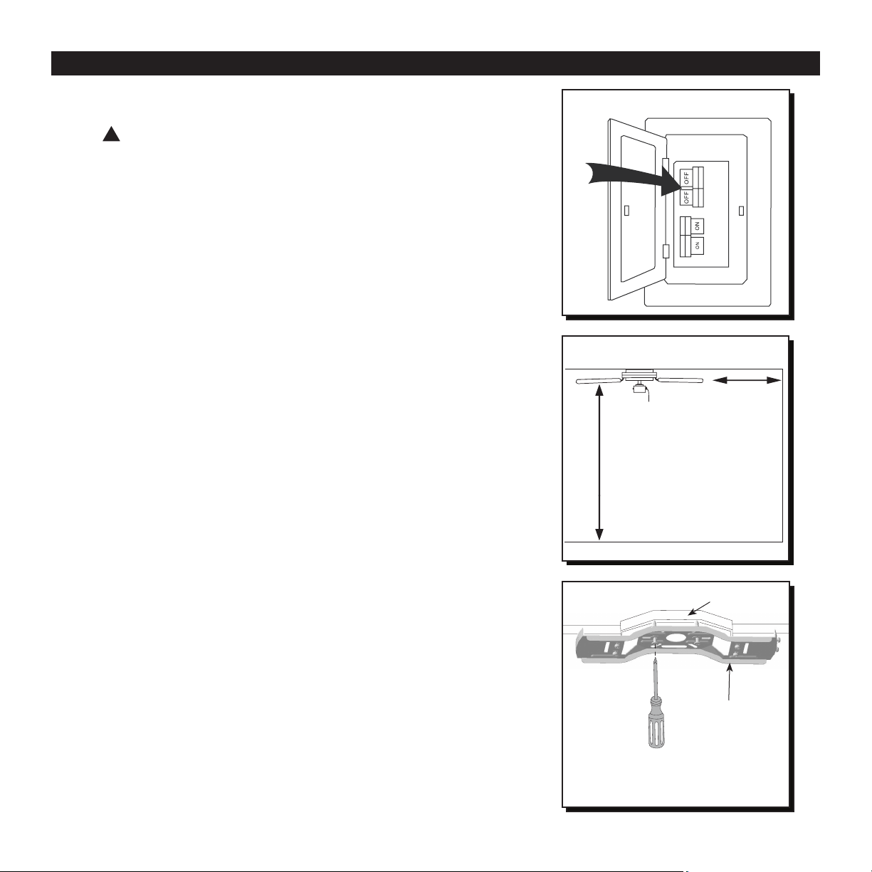
MOUNTING BRACKET INSTALLATION
1. Turn OFF the electrical power at the main fuse or
circuit breaker (Fig. 1).
!
DANGER: Failure to disconnect the power
supply prior to installation may result in serious
injury or death.
2. Ensure that the blades will be at least 30 in. (76 cm)
from any obstruction and at least 7 ft. (2,13 m) above
the oor (Fig. 2).
Fig. 1
Fig. 2
30" Min
7' Min
3. Secure the upper mounting bracket to the outlet box
using screws provided with the outlet box (Fig. 3).
Note: It is very important that you use the proper
hardware when installing the mounting bracket as
this will support the fan.
Fig. 3
Outlet Box
Upper Mounting
Bracket
5
 Loading...