

Page 1
Industrial Air Vent
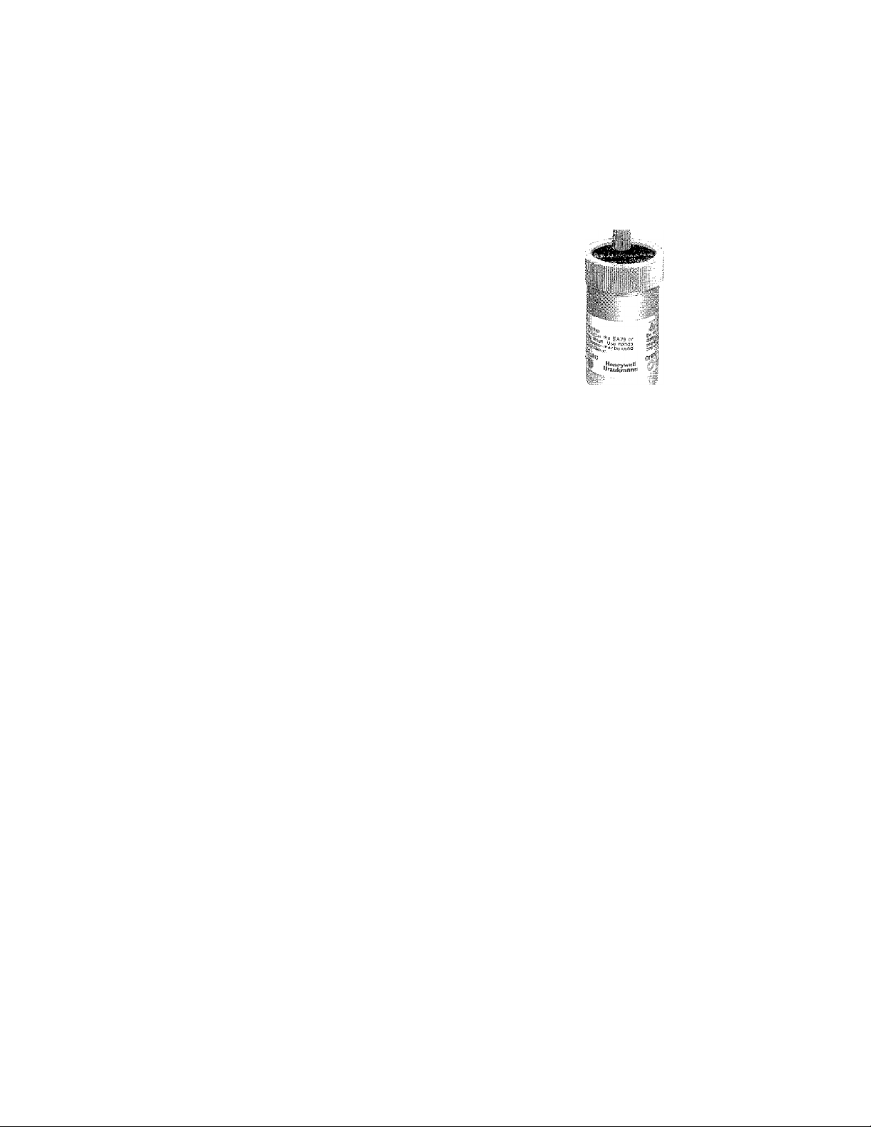
The Honeywell Braukmann EA79 Industrial
AirVentpurges air from highpressure mains and
equipment in hot or cold closed water systems.
Honeywell Braukmann
EA79
ff
Includes built-in shutoff valve for servicing with
out system shutdown.
Removable float/valve assembly for easy servicing.
includes safety drain connection and vent cap with
leakage guard.
Brass shell construction.
Internal parts made of corrosion-resistant and
chemical-resistant materials for use with water
systems containing glycol, mineral oils, or petro
leum-based oils.
For use with water systems up 250° F [120° C].
3/4 in. NPT male pipe thread with 1/2 in. NPT
female pipe thread connections.
Maintains quiet and efficient operation.
CONTENTS
Sp ecificalions. i. i.
Ordering ihfprtnMan
Installation
Operation
Service
Troubleshopting.:. ,.
...................
.2
..2
.3
..4
..4
,.5
C.H. ■ 10-92 ” © Honeywell Inc. 1992 ■ Form Nundrer 62-3034
Page 2
E/^
SPECiFICATIONS • ORDERINgInFORMATÌON
Specifications
MATERIALS OF CONSTRUCTION:
Body: Brass.
Cover ring: Brass.
Float, valve lever and cover: Engineered thermoplastics.
Seal disc and rings: Synthetic rubbers.
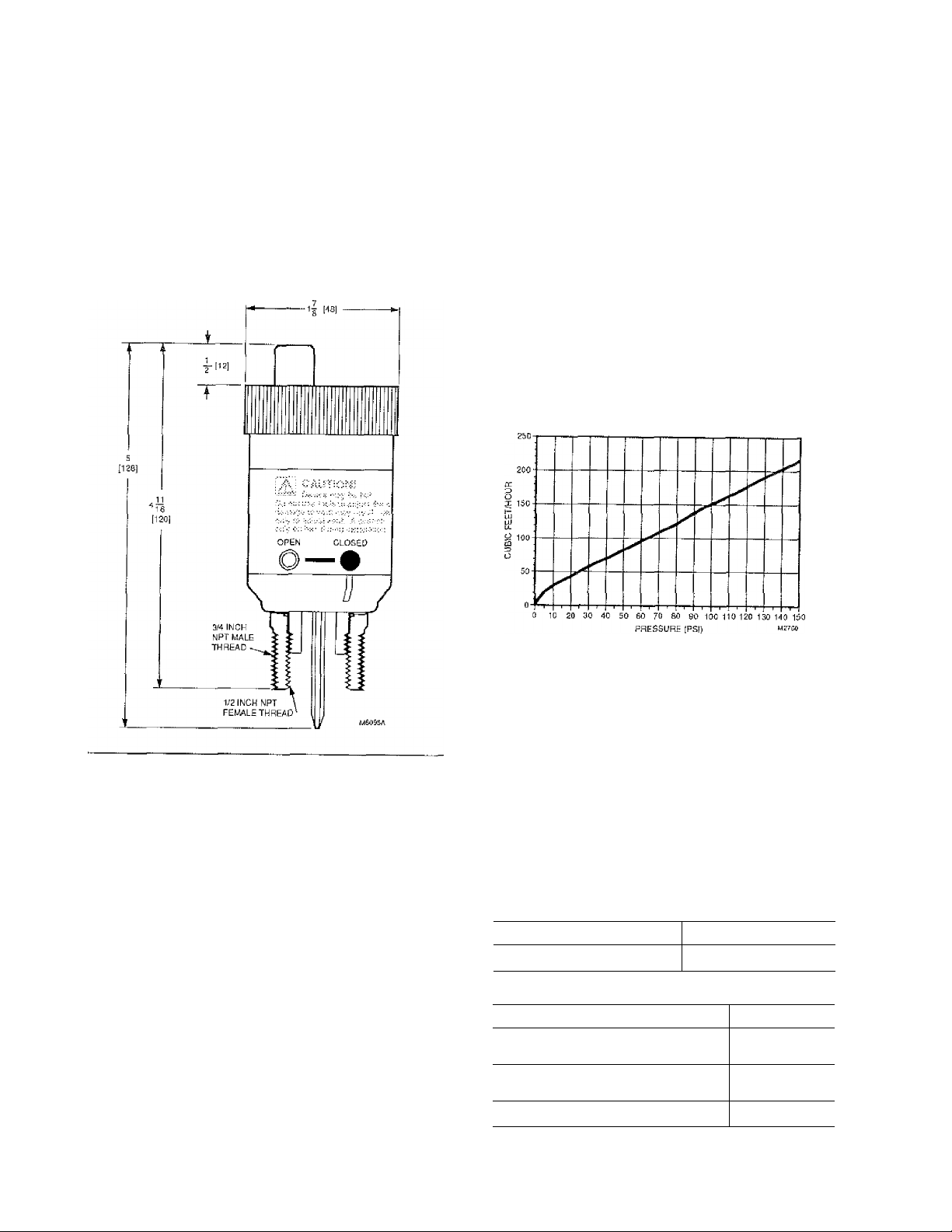
Fig. 1—EA79 dimensions in in. [mm].
OPERATING RATINGS:
Maximum Pressure; 150 psi
Maximum Temperature; 250° F [120° C]
SAFETY RATINGS:
Maximum Pressure: 450 psi
Maximum Temperature: 250° F [120° C]
CONNECTIONS: 3/4 in. NPT male pipe thread with 1/2 in.
NPT female pipe thread.
DIMENSIONS: Refer to Fig. 1.
CAPACITTES: Refer to Fig. 2.
Fig. 2—EA79 flow capacities, with leakage guard
cap.
NOTE: Capacity indicated is for device with leakage guard
cap correctly installed and operational. Additional capac
ity may be obtained by removing the leakage guard cap
and installing a connection between the vent discharge
and drain using Q122A1001 Safe Waste Connector.
Ordering Information
When purchasing replacemenr and modernization products, specify Ore complete model number.
1. If you have additional questions, need further information,
or want to comment on our products or services, call;
l-SOO-345-6770, ext. 7188.
Or write;
Honeywell Customer Assistance Center
Honeywell Plaza, MN27-2164, P.O. Box 524
Minneapolis, Minnesota 55440-0524
2. To place an order, contact:
Honeywell Braulanann Customer Service
1985 Douglas Drive North
Minneapolis, Minnesota 55422-3992
(612)542-7106 (Eastern US)
(612) 542-7103 (Western US)
3. Or fax your order to 1-800-356-0149.
INDUSTRIAL AIR VENT:
Description
Industrial automatic air vent
ACCESSORIES:
Description
Cover assembly—includes replacement
0 ring, cover and float assembly.
Safe waste connector for connecting
top vent to 1/4 in. O.D. tube.
Red vent cap with leakage guard.
Model Number
EA79A1004
Part Number
P79B1003
Q122A1001
^204992
Page 3

_________
INSTALLATION
Installation
EA79
WHEN INSTALLING THIS PRODUCT...
1. Read these instructions carefully. Failure to follow
them could damage the product or cause a hazardous
condition.
2. Check the ratings given in the instructions and on
the product to make sure the product is suitable for your
application,
3. Installer must be a trained, experienced service
technician,
4. After installation is complete, check out product
operation as provided in tliese instructions.
f\ CAUTION
Do not use tools to adjust the EA79 or damage
to vent may result, Use hands only to adjust
vent. A wrench may be used only on hex during
installation.
LOCATION
Install the EA79 on the positive side of tlie circulator
pump at the point where air will accumulate. This is usually
the high point of the supply or the retum main in the system
as shown in Fig, 3.
INSTALLATION
1. Fit EA79 vent in piping at a location as specified in
the Location section,
2. Turn EA79 until vent fits tightly on piping. Use a
wrench to securely tighten hex.
3. If safety drain connection is desired, inslali a pipe
between vent discharge and drain using Q122A1001 Safe
Waste Connector.
4. Make sure that the red vent cap is securely tight, and
that the valve is in the closed position by turning vent body
clockwise. See Fig. 4. U,se hands only to avoid damaging
the vent.
5. With the valve in the closed position, flush the system
as required to remove dirt, debris and contaminants.
6. Fill the system with the appropriate solution.
7. Operate the EA79 by turning the air vent body coun
terclockwise to the open position. Use hands only, .see Fig. 4.
8. Make sure the red vent cap is tightened all Ihe way
to the slop position for proper leakage guard operation.
Use hands only to tighten.
Fig. 4—Turn vent body counterclockwise to
open or clockwise to close.
Fig. 3—Install EA79 at high point in system.
BETWEEN VALVE DISCHARGE AND DRAIN
INSTALL EA79 AT HIGH POINT IN SYSTEM,
62-3034
Page 4

£A79
__________________
OPERATION ® SERVICE
Operation
The EA79 operates as Ibllows:
Opening the air vent (Lurning valve body counterclock
wise) exposes tiie EA79 to the system. Water and air may
enter the vent chamber. The float will fall through any air in
the cliambcr. This opens the vent scat.
The red ven t cap aliows air to pass through the open vent.
As the air is released through tlie vent cap, water replaces
!\ CAUTION
The EA79 may be hot due to system temperature
extremes. Use caution when adjusting vent to pre
vent bunting hands.
The EA79 may become accumulated with dirt in the seat
area of the float assembly, which may cause itie vent to
malfunction. Periodic cleaning is recommended to prevent
the vent from malfunctioning.
NOTE: The EA79 may be serviced without depressurizing
or draining the system.
tiieairin the vent chamber and the floatrises. This closes the
vent seal. When additional air enters the vent chamber, the
operation repeats.
If the vent seat remains open, water will rise through the
vent and cause the swelling disks inside the red cap to close
off the vent. Closing the air vent (turning valve body clock
wise) isolates theEA79 from the system, allowing service.
Service
9. Make sure the red vent cap is tightened all the way
to the Slop position for proper leakage guard operation.
Use hands only to tighten.
Fig. 5—EA79 construction.
■ OUTER RIWG
To clean the seat area, proceed as follows:
1. Turn the vent body clockwise to the closed position,
isolating the vent from the system. See Fig. 4.
2. Remove the float assembly by unscrewing the outer
ring at the top of Lhe body and lifting up the black cover
assembly. See Fig. 5.
3. Carefully clean the scat area of any din or debris.
i\ CAUTION
Do not bend spring on float assembly or damage to
the vent may result.
4. Carefully clean any dirt or debris from inside the
vent chamber.
5. Replace the float assembly, making sure that the O
ring is seated properly (see Fig. 5).
6. Replace black cover assembly on air vent body.
7. Using hands only, replace outer ring, turning until
hand tight.
8. Operate the E A79 by turning the air ventbody counter
clockwise to the open position. Use hands only. See Fig. 4,
Page 5

!\ CAUTION
The EA79 may be hoi due to system temperature
extremes. Use caution when adjusting vent to pre
vent burning hands.
_______________
TROUBLESHOOTING
Troubleshooting
EA79
Problem
The EA79 is not venting air or
there is too much air in the system.
Water is leaking from the EA79.
Action
1. Check the red vent cap; make sure the vent passage is open (disks are
not swelled).
2. Check that th.e valve is in the open position.
3. Make sure that the float is attached to the vent lever as shown in Fig. 5.
1. Make sure the red vent cap is tightened all the way to the stop position.
2. Adj ust the valve to the closed position by turn ing the vent body clockwise.
3. Clean the vent as described in the Service section.
4. If internal parts appear damaged or deteriorated, replace cover assembly
(part no. P79B1003).
62-3034
Page 6

Honeywell Braukmann
Honeywell Braukmann
Honeywell Inc.
1985 Douglas Drive North
Golden Valley, Miimesota 55422
Printed in U.S.A.
Helping You Coftlrol Your World
 Loading...