

Page 1
DT8360CM-SN / DT8360ACM-SN DUAL TEC® Ceiling
Mount Motion Sensor
Installation Instructions
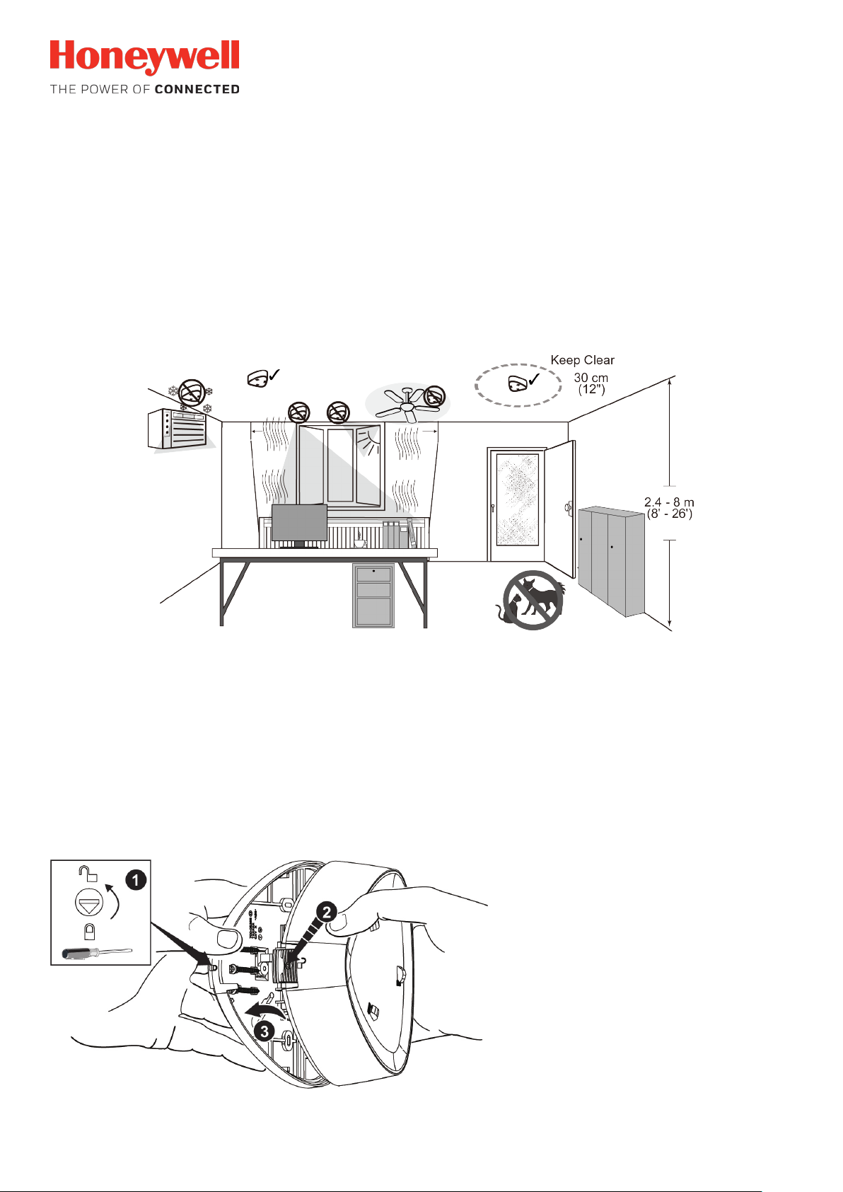
1. Select the Mounting Location
Mounting location guidelines:
• The range is obtained at a mounting height of 2.4m (8’) to 8m (26’). Max. detection range at 8m (26’) is Ø 21m (70’).
• Allow a clear line-of-sight to all areas to protect.
• Avoid mounting anything within 30cm (12”) in front of the sensor.
• Do not directly face windows.
• Avoid close proximity to moving machinery, fluorescent lights, and heating/cooling sources. Avoid use in turbulent air.
• Not for use in applications with pets.
2. Open the Sensor
1. Turn the arrow to point to the Unlock symbol.
2. Press firmly on housing latch.
3. Gently separate the front and rear housing.
- 1 -
Page 2
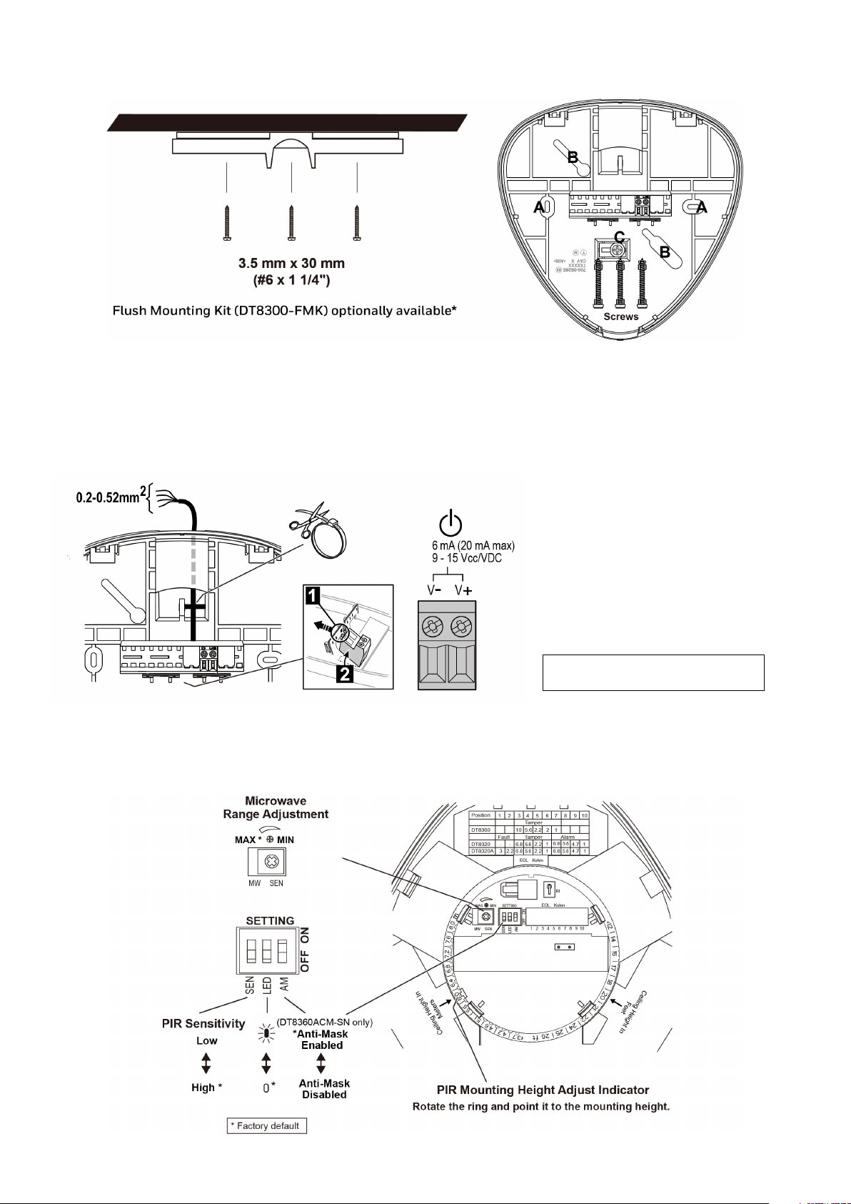
3. Mount the Sensor
Note: Observe proper polarity.
[A] = Fixed mounting holes
[B] = Adjustable mounting slots from 61mm-85mm (2.4”-3.3”)
[C] = Tamper hole
*This accessory is not covered by the approval.
4. Wire the Sensor
For new polling loop installations,
always use shielded twisted pair
wiring. In many cases, existing nontwisted pair wiring may be used, but it
is more susceptible to interference
from other sources, and may be
problematic in installations with long
wire runs or in high noise
environments.
Shielded wiring must be used.
5. Sensor Components and Settings
- 2 -
Page 3
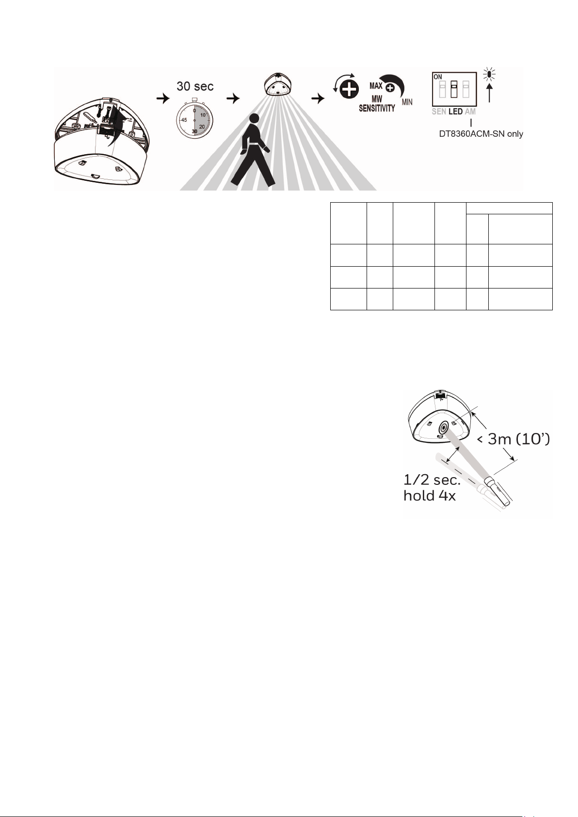
6. Walk Test the Sensor and Adjust as Needed
maximum, the sensor range is Ø 21m (70’).
Power
Trouble
only)
PIR
1. Use a flashlight with a bright light beam, and stand within 3m (10’) of the sensor.
1. Close the sensor and apply power to the sensor. Initialization is
complete when the LED stops flashing slowly (about 30 seconds).
2. Walk through the detection area and observe the LED.
3. Adjust the microwave range as necessary to meet installation
requirements.
Walk test mode is active for 15 minutes, then automatically exits test
mode, disables the LED and enters normal operation mode. For an
additional 15 minute walk test, enable walk test mode again with the
flashlight feature.
Notes:
• During power up and walk test modes the LED is active regardless
of the LED Enable/Disable DIP switch setting.
• When the microwave sensitivity is set to minimum, the sensor range
is reduced to Ø 12m (40’). When the microwave sensitivity is set to
LED
Red
Yellow OFF
Green OFF
Up
Slow
Blink
Walk Test
[15 min.]
ON
Alarm
ON
Microwave
ON
Normal
ON
Alarm
OFF OFF
OFF OFF OFF
Anti-Mask
Fault
(DT8360ACM-SN
Fast
OFF
Blink
Fast
Blink
Flashlight Feature:
2. Swing the light beam past the sensor IR window 3-5 times consistently, holding the
beam on the window for 0.5 second each pass.
Notes:
• The flashlight feature is available for the first 24 hours after power up.
•
The flashlight feature only works with incandescent bulb flashlights. It does not work
with LED flashlights.
- 3 -
Page 4
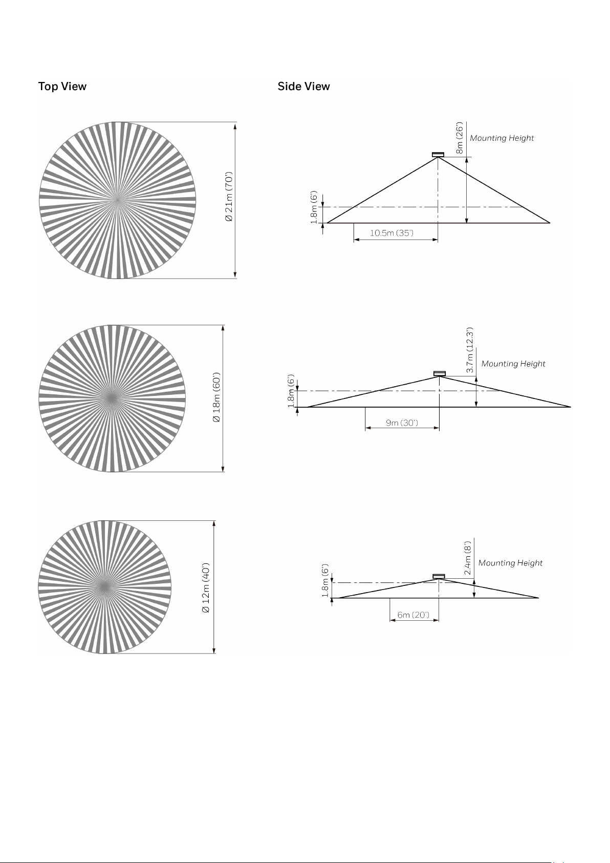
7. Detection Patterns
Note: Attention detection beams go across access points such as windows, doors during sensor installation.
- 4 -
Page 5
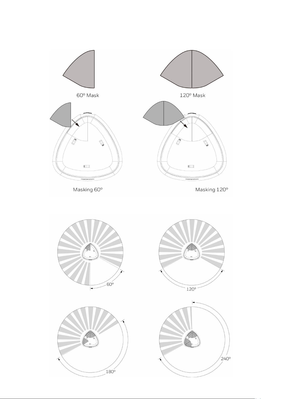
8. Coverage Pattern Masking (DT8300-CPM)
A set of 60° masks are provided for masking undesired areas. Attach the masks on the outside of the detector.
With the supplied masks, you can mask 60°, 120°, 180° or 240°. Refer to the following examples:
Note: To mask a certain area, attach the mask on the opposite side of the sensor, referring to the following examples.
- 5 -
Page 6
TROUBLE*
NORMAL
Low
Voltage2
Self-Test
Failure3
Red LED
Off
Off
Off
Flashing
Yellow LED
Off
Flashing
Off
Off
MASK CONDITION (DT8360ACM-SN only)
Normal Anti-Mask Condition
The sensor uses Active Infrared (AIR) technology to detect
masking. The sensor signals a mask condition when a
variety of materials and reflective objects are placed within
50mm (2 inches) in front of the sensor. To avoid false
mask alarms, follow the mounting guidelines shown in
Step 1.
Clearing an Anti-Mask Condition
When most masking materials or objects are removed, the
anti-mask condition will be cleared after several seconds.
When the cause of the anti-mask condition is any type of
spray or paint coating applied to the window, the window
must be replaced before the anti-mask condition can be
cleared. After replacing the window, perform a walk-test on
the sensor.
TROUBLESHOOTING
Mask1
SPECIFICATIONS
Range: Ø 21m max.
Mounting Height: 2.4m – 8m
IP Rating: IP30
Power: 9.0 - 15 VDC; 6 mA standby (V-Plex@ version),
20 mA max., 12 VDC;
AC Ripple: 3 V peak-to-peak at nominal 12 VDC
Tampers: Cover & Wall; (NC with cover installed) Form A;
30 mA, 25 VDC; Magnetic field
Microwave Frequencies Range: 10.5 – 10.55GHz
RFI Immunity: 20V/m, 80MHz-1GHz
PIR White Light Immunity: 6,500 Lux typical
Fluorescent light filter: 50 Hz / 60 Hz
Operating Temperature: -10℃ - 55℃
Relative Humidity: 5 to 95%; non-condensing
Temperature Compensation: Advanced Dual Slope
Dimensions: 14.8 cm x 16.2 cm x 4.7 cm
*TROUBLE CONDITIONS:
1. Mask condition: Sensor IR window is blocked or
masked.
2. Low Voltage: The sensor is disabled. Note: If voltage
drops below 5V, both Alarm and Trouble relays open.
3. Self-Test Failure conditions:
• Microwave supervision failure: The sensor is
operating in PIR mode only.
• PIR self-test failure: The sensor is disabled.
• Temperature compensation failure: The
temperature compensation is disabled.
Depending on the Trouble condition, take the following
corrective actions:
• Verify the sensor is not blocked or masked.
• Verify the power supply is sufficient (at least 9V at the
sensor).
• Cycle power to the sensor.
• Walk test the sensor.
If the Trouble condition does not clear, replace the sensor.
Notes
• Install the devices and system in the isolated and
dedicated network system with physical security.
• Ensure only the authorized technician may access
and operate the device.
• Ensure to have regular system maintenance and
check the device functionalities work normally.
• Access
us/vulnerability-reporting to report any vulnerability.
https://www.honeywell.com/contact-
- 6 -
Page 7

GA 30308
Document 800-24708 Rev. C
APPROVAL/ LISTINGS
• FCC part 15, Class B verified
• IC ICES-003, Cla ss B verified
• UL 639
• ULC S306-03
• SIA-PIR-01 Passive Infrared detector standard features for false alarm immunity.
Product must be tested at least once each year / Le fonctionnement du produit doit être vérifié au moins une fois par année / El producto debe ser probado al
menos una vez al año / O produto deve ser testado pelo menos uma vez por ano
All wiring must be in accordance with: the National Electrical Code (ANSI/NFPA70); the Canadian Electrical Code, Part I (where applicable); UL681, Standard for
Installation and Classification of Burglar and Holdup Alarm Systems; ULC-S302, Standard for Installation and Classification of Burglar Alarm Systems for
Financial and Commercial Premises, Safes and Vaults; ULC-S310, Standard for Installation and Classification of Residential Burglar Alarm Systems; local codes
and the authorities having jurisdiction.
The products are int ended to be powered by a power-limited output of a UL/CUL Listed Burglar Alarm control unit, or via a Listed UL603/ULC-S318 power-limited
power supply that provides 4 hours of standby power.
The sensor must be mounted indoors, within the protected premises, and on a wooden stud, solid wood or with a robust wall anchor.
UL Note: All interconnecting devices must be UL Listed.
FEDERAL COMMUNICATIONS COMMISSION STATEMENTS
The user shall not make any changes or modifications to the equipment unless authorized by the Installation Instructions or User's Manual. Unauthorized
changes or modifications could void the user's authority to operate the equipment.
CLASS B DIGITAL DEVICE STATEMENT
This equipment has been tested to FCC requirements and has been found acceptable for use. The FCC requires the following statement for your information:
This equipment generates and uses radio frequency energy and if not installed and used properly, that is, in strict accordance with the manufacturer's
instructions, may cause interference to radio and television reception. It has been type tested and found to comply with the limits for a Class B computing
device in accordance with the specifications in Part 15 of FCC Rules, which are designed to provide reasonable protection against such interference in a
residential installation. However, there is no guarantee that interference will not occur in a particular installation. If this equipment does cause interference to
radio or television reception, which can be determined by turning the equipment off and on, the user is encouraged to try to correct the interference by one or
more of the following measures:
• Reorient th e receiving antenna until interference is reduced or eliminated.
• Move the radio or television receiver away from the receiver/control.
• Move the antenna leads away from any wire runs to the receiver/control.
• Plug the receiver/control into a different outlet so that it and the radio or television receiver are on different branch circuits.
• Consult the dealer or an experienced radio/TV technician for help.
INDUSTRY CANADA CLASS B STATEMENT
This Class B digital apparatus complies with Canadian ICES-003.
Cet appareil numérique de la classe B est conforme à la norme NMB-003 du Canada.
FCC / IC STATE MENT
This device complies with Part 15 of the FCC Rules, and Industry Canada’s license-exempt RSSs. Operation is subject to the following two conditions: (1) This
device may not cause harmful interference, and (2) This device must accept any interference received, including interference that may cause undesired
operation.
Cet appareil est conforme à la partie 15 des règles de la FCC et exempt de licence RSS d’Industrie Canada. Son fonctionnement est soumis aux conditions
suivantes: (1) Cet appareil ne doit pas causer d’interférences nuisibles. (2) Cet appareil doit accepter toute interférence reçue y compris les interférences
causant une réception indésirable.
To protect the environment, a detailed installation guide is available on the Honeywell website – Please consider before
printing the document!
2019 Honeywell International Inc.
Honeywell and DUAL TEC are registered trademarks
of Honeywell International Inc. All other trademarks
are the properties of their respective owners. All
rights reserved.
715 Peachtree Street, N.E. Atlanta.
 Loading...