

Page 1

DCP 50
Digital Controller Programmer
Product Manual
57-77-25-17
3/00
Sensing and Control
Page 2

Copyright, Notices, and Trademarks
WARRANTY/REMEDY
Honeywell warrants goods of its manufacture as being free of defective materials and faulty
workmanship. Contact your local sales office for warranty information. If warranted goods are
returned to Honeywell during the period of coverage, Honeywell will repair or replace without
charge those items it finds defective. The foregoing is Buyer’s sole remedy and is in lieu of all
other warranties, expressed or implied, including those of merchantability and fitness for a
particular purpose. Specifications may change without notice. The information we supply is
believed to be accurate and reliable as of this printing. However, we assume no responsibility for
its use.
While we provide application assistance personally, through our literature and the Honeywell
web site, it is up to the customer to determine the suitability of the product in the application.
Printed in U.S.A. – © Copyright 2000 by Honeywell
Revision – 3/00
Sensing and Control
Honeywell
11 West Spring Street
Freeport, Illinois 61032
Page 3

About This Document
Abstract
The purpose of this manual is to support the installation, configuration, and operation of the DCP 50
Digital Controller Programmer.
Contacts
World Wide Web
The following lists Honeywell’s World Wide Web sites that will be of interest to our customers.
Honeywell Organization WWW Address (URL)
Corporate http://www.honeywell.com
Sensing and Control http://www.honeywell.com/sensing
International http://www.honeywell.com/Business/global.asp
Telephone
Contact us by telephone at the numbers listed below.
Organization Phone Number
United States and Canada Honeywell 1-800-423-9883 Tech. Support
1-888-423-9883 Faxback
1-800-525-7439 Service
Asia Pacific Honeywell Asia Pacific
Hong Kong
Europe Honeywell PACE, Brussels, Belgium [32-2] 728-2111
Latin America Honeywell, Sunrise, Florida U.S.A. (854) 845-2600
(852) 2829-8298
Page 4

Page 5

HONEYWELL DCP 50
DIGITAL CONTROLLER/PROGRAMMER
PRODUCT MANUAL
CONTENTS
1 BASE MODE 1-1
1.1 DISPLAY SEQUENCE - NO PROGRAM RUNNING 1-1
1.2 STARTING A PROGRAM 1-2
1.3 PUTTING A PROGRAM IN HOLD 1-2
1.4 RELEASING A PROGRAM FROM HOLD 1-2
1.5 ABORTING A PROGRAM 1-2
1.6 DISPLAY SEQUENCE - PROGRAM RUNNING 1-3
1.7 RaPID CONTROL FEATURE 1-4
1.8 PRE-TUNE FEATURE 1-4
1.9 ENGAGING BOTH PRE-TUNE AND RaPID FEATURES 1-5
1.10 INDICATION OF PRE-TUNE AND RaPID STATUS 1-5
1.11 VIEWING THE HARDWARE DEFINITION CODE 1-6
1.12 MANUAL CONTROL 1-7
2 INSTALLATION 2-1
2.1 UNPACKING PROCEDURE 2-1
2.2 PANEL-MOUNTING THE CONTROLLER 2-1
(v)
Page 6

2.3 CONNECTIONS AND WIRING 2-2
3 PROGRAM DEFINITION MODE
- CREATING/EDITING A PROGRAM 3-1
3.1 ENTRY 3-1
3.2 CREATING A PROGRAM 3-2
3.3 DEFAULT VALUES AND ADJUSTMENT RANGES 3-9
3.4 EXIT FROM PROGRAM DEFINE MODE 3-9
4 CONTROLLER SET-UP MODE 4-1
4.1 PARAMETER DETAILS 4-3
4.2 EXIT FROM CONTROLLER SET-UP MODE 4-9
5 MODBUS COMMUNICATIONS 5-1
5.1 INTRODUCTION 5-1
5.2 MODBUS FUNCTIONS SUPPORTED 5-1
5.3 MESSAGE FORMATS 5-1
5.4 PARAMETER NUMBERS 5-7
5.5 PROFILER STATUS BYTE 5-11
5.6 PROFILER COMMANDS 5-11
6 CONFIGURATION MODE 6-1
6.1 ENTRY INTO CONFIGURATION MODE 6-1
6.2 HARDWARE DEFINITION CODE 6-1
6.3 OPTION SELECTION 6-3
6.4 CONFIGURATION MODE PARAMETERS 6-4
6.5 EXIT FROM CONFIGURATION MODE 6-9
(vi)
Page 7

7 INTERNAL LINKS AND SWITCHES 7-1
7.1 REMOVING THE CONTROLLER PROGRAMMER FROM ITS HOUSING 7-1
7.2 REMOVING/REPLACING THE OUTPUT 2/OUTPUT 3 OPTION PCBs 7-3
7.3 REMOVING/REPLACING THE RS485 COMMUNICATIONS OPTION PCB
OR REMOTE RUN/HOLD OPTION PCB 7-3
7.4 REPLACING THE INSTRUMENT IN ITS HOUSING 7-3
7.5 SELECTION OF INPUT TYPE AND OUTPUT 1 TYPE 7-4
7.6 OUTPUT 2 TYPE/OUTPUT 3 TYPE 7-6
A PRODUCT CODES A-1
B PRODUCT SPECIFICATION B-1
C SUMMARY OF DISPLAYS C-1
(vii)
Page 8
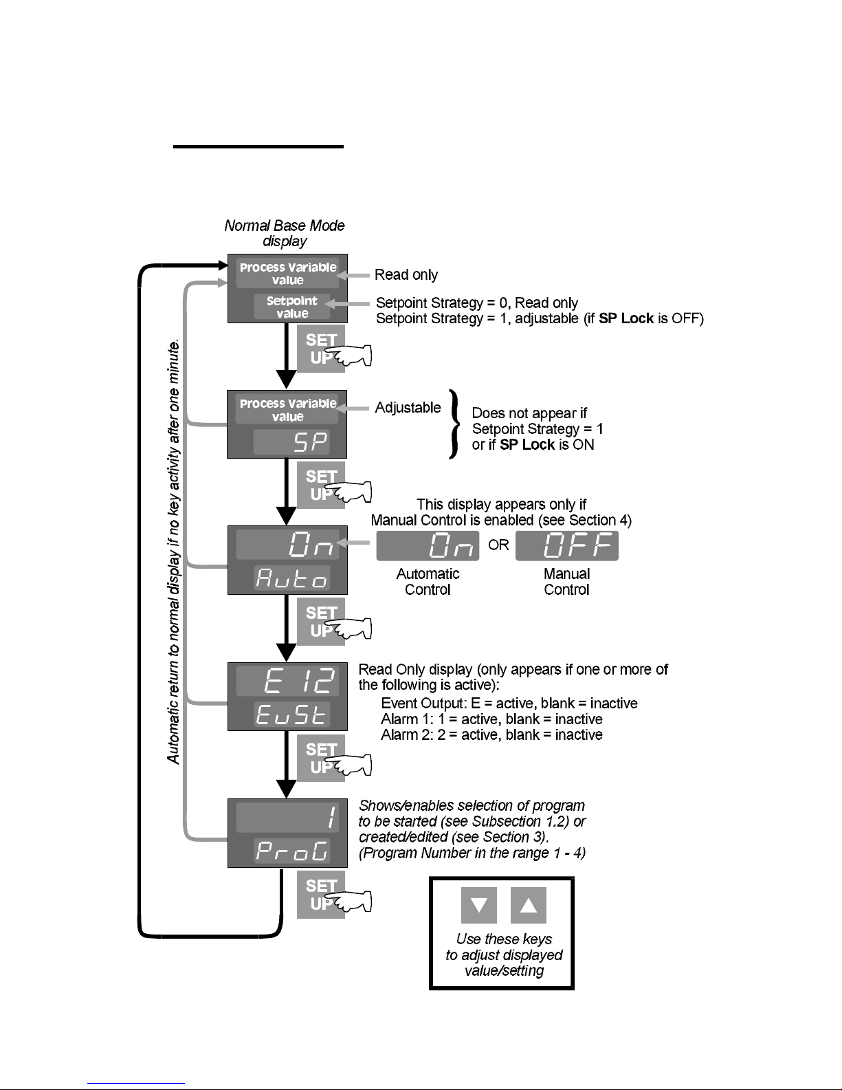
1 BASE MODE
1.1 DIS P L A Y SEQUENCE - NO PROGRAM RUNNING
1-1
Page 9
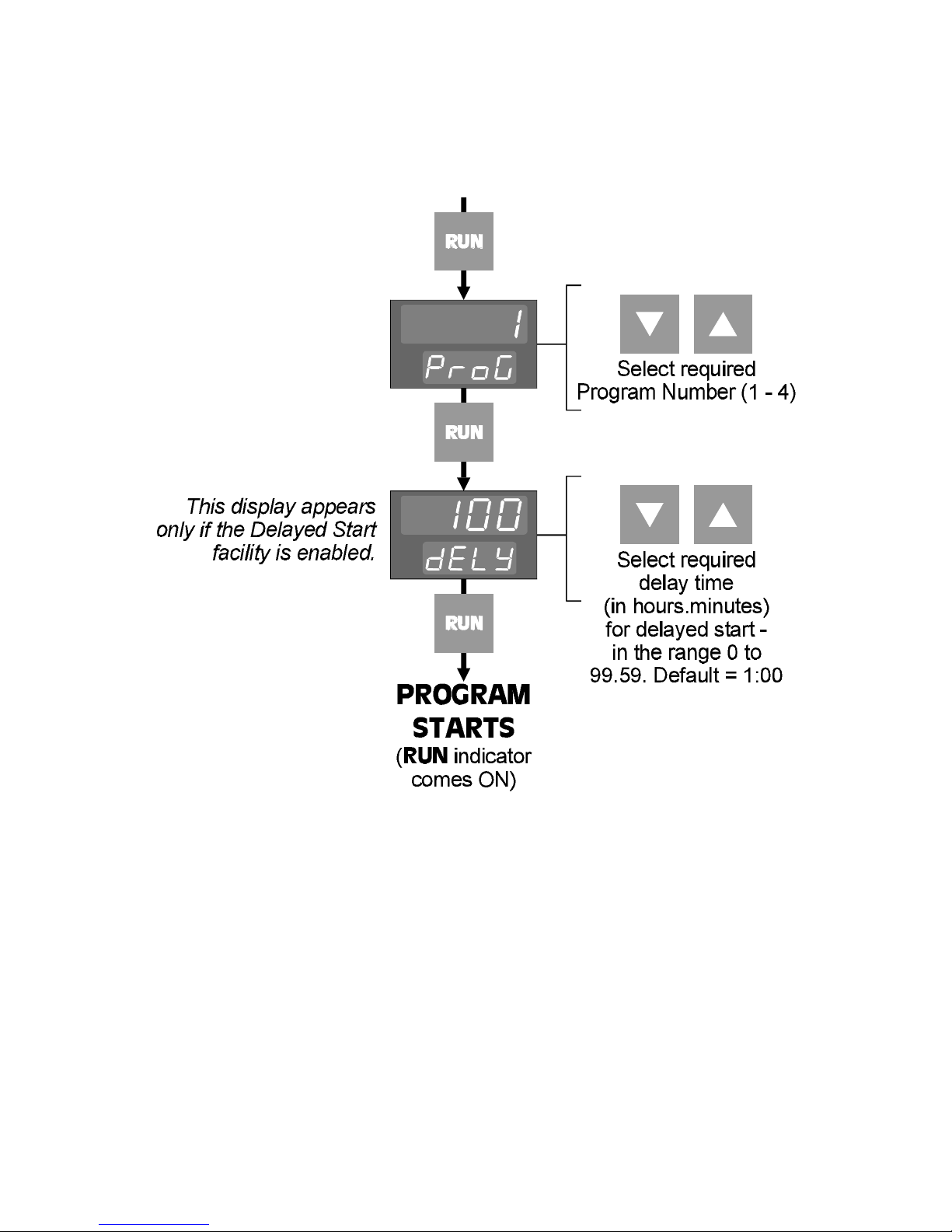
1.2 STARTING A PROGRAM
To start a program running:
1.3 PUTTING A PROGRAM IN HOLD
A program can be put in Hold (i.e. frozen) at any time whilst it is running. The program
setpoint will stay at its value at the instant the program entered Hold until the
program is released (see Subsection 1.4) or aborted (see Subsection 1.5). To put a
program in hold, momentarily press the RUN key. The RUN indicator will flash whilst
the program is in hold.
1.4 RELEASING A PROGRAM FROM HOLD
To release a program currently in Hold, momentarily press the RUN key. The RUN
indicator will then go ON continuously.
1 -2
Page 10
1.5 ABORTING A PROGRAM
To abort the current-running (or held) program, hold down the RUN key for 5
seconds. The program will be aborted, the RUN indicator will go OFF and the
normal Controller functions will be resumed.
NOTE: When a program is aborted, the instrument returns to the Controller
setpont value. If a program is successfully completed, the Controller setpoint is
automatically set to the final setpoint value of the program. If it is desired to
restore the initial Controller setpoint value after the program is completed,
theis value should be used as the program's Final Setpoint Value.
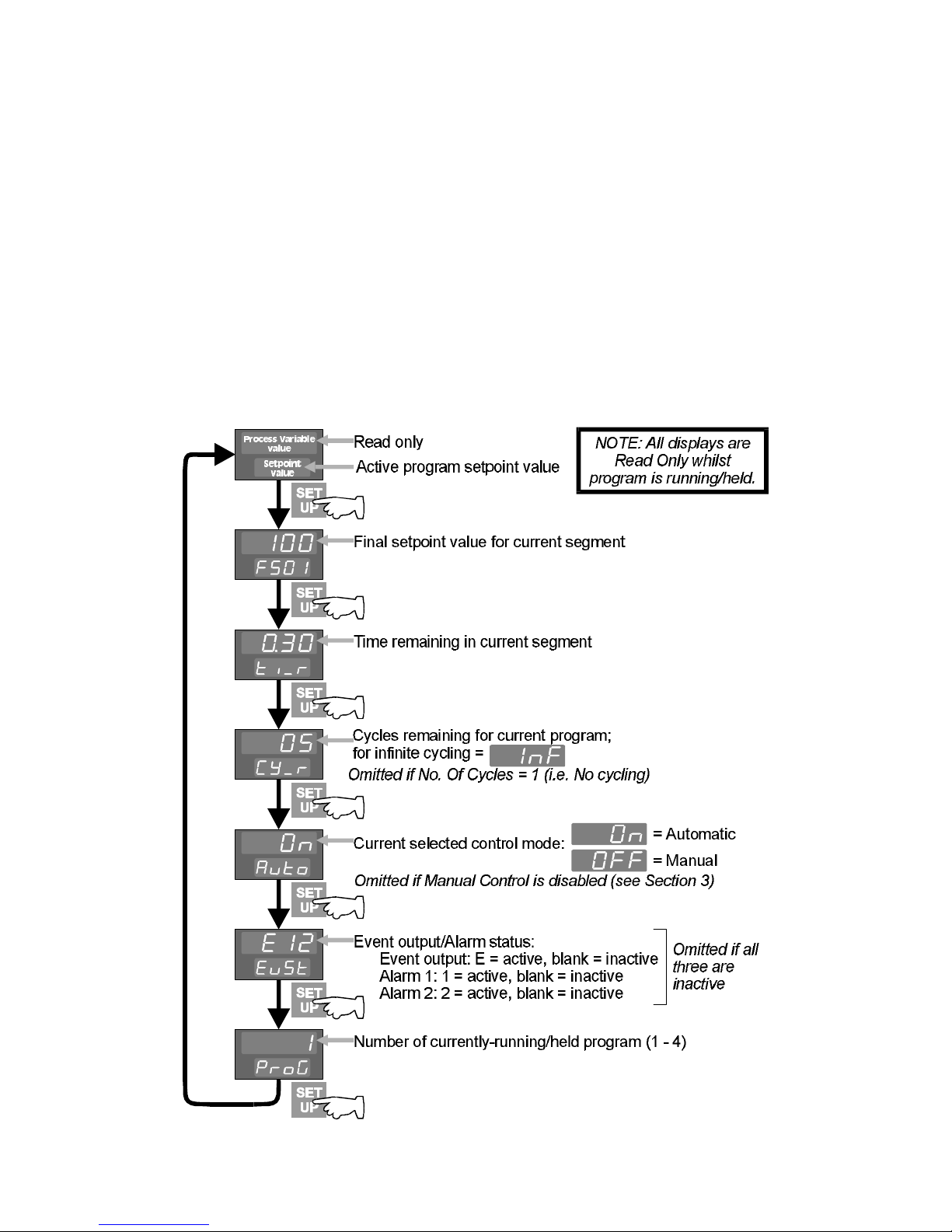
1.6 D ISPLA Y SE Q U EN CE - PROGRAM RUNNING
1-3
Page 11
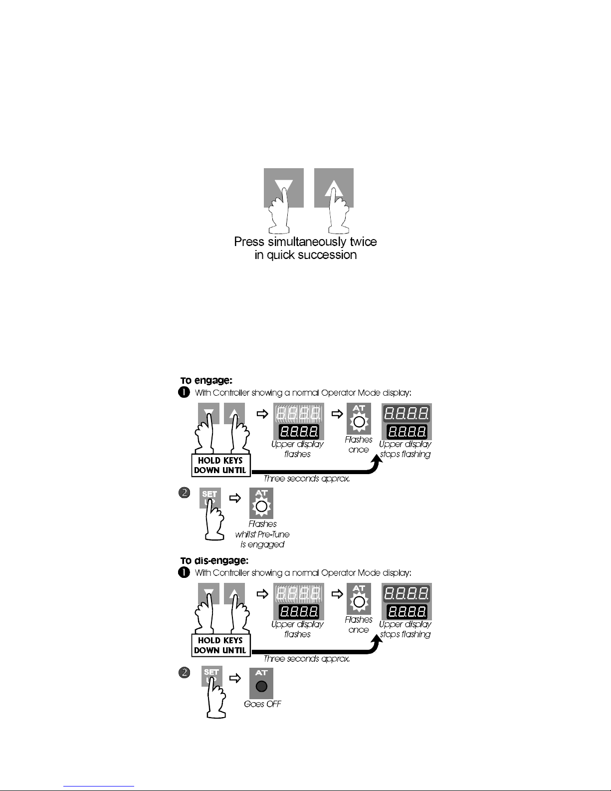
1.7 RaPID CONTROL FEATURE
The RaPID control feature may be used when extra fast responses and minimum
overshoot are required. The RaPID feature works best when PID terms are well-tuned;
therefore, it is recommended that the Pre-Tune feature (see Subsection 1.8) is run
before the RaPID feature is engaged.
To dis-engage RaPID control, use the same key actions. NOTE: The RaPID feature
cannot be engaged if Proportional Band 1 or Proportional Band 2 is set to 0.
1.8 PRE-TUNE FEATURE
This facility may be used to provide initial tuning of the Controller’s PID parameters.
Pre-Tune may be engaged (and subsequently dis-engaged) as follows:
1-4
Page 12
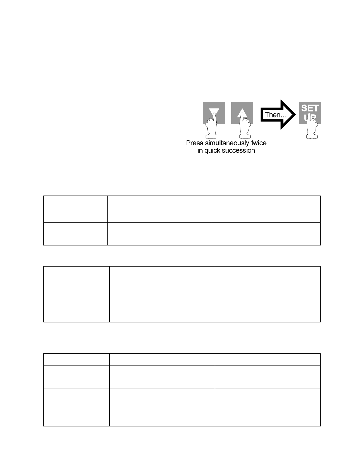
NOTE: The Pre-Tune facility will not engage if (a) a program is currently running,
(b) the process variable is within 5% of input span of the setpoint, or (c) an
erroneous key sequence is used. Pre-Tune is a single-shot process which
automatically dis-engages itself when completed.
1.9 ENGAGING BOTH PRE-TUNE AND RaPID FEATURES
The Pre-Tune and RaPID features can be
engaged in one key action sequence
(see right). Pre-Tune will operate first. When
it is completed it will dis-engage itself and
the RaPID feature will then operate
automatically.
1.10 INDICATION OF PRE-TUNE AND RaPID STATUS
The responses to the RaPID feature being engaged are:
Pre-Tune Status Response Indication
Not operational. RaPID activated.
Operational. Pre-Tune completes routine,
then RaPID activated.
The responses to the RaPID feature being dis-engaged are:
Pre-Tune Status Response Indication
Not operational. RaPID de-activated.
Operational. Pre-Tune completes routine,
then RaPID de-activated return to normal control.
The responses to Pre-Tune being engaged are:
RaPID status Response Indication
Not operational. Pre-Tune activated and
routine completed
AT indicator goes ON.
AT indicator flashes at double
rate then comes ON.
AT indicator goes OFF.
AT indicator flashes at
double rate then goes OFF.
AT indicator flashes at
normal rate the goes OFF.
Operational. RaPID interrupted, Pre-Tune
activated. Pre-Tune completes
routine, then RaPID control
resumed.
1-5
AT indicator flashes at
double rate then goes ON.
Page 13
The responses to Pre-Tune being dis-engaged (manually or automatically) are:
RaPID Status Response Indication
Not operational. Pre-Tune dis-engaged, normal
AT indicator goes OFF.
control resumed.
Operational. Pre-Tune dis-engaged, RaPID
AT indicator goes ON.
control resumed.
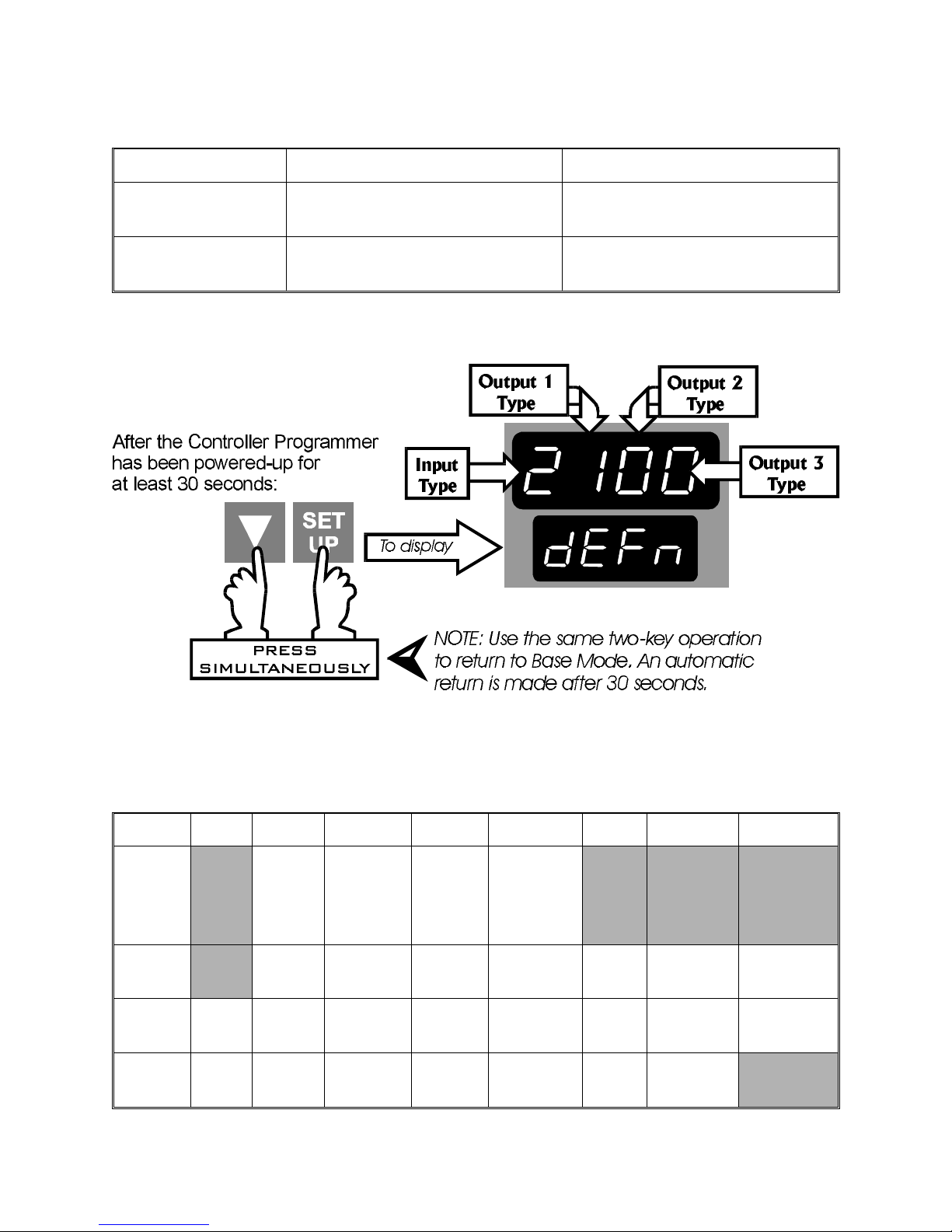
1.11 VIEWING THE HARDWARE DEFINITION CODE
NOTE: An automatic return is made to the normal Base Mode display after 30
seconds.
The Hardware Definition Code has the following significance:
Value 0 1 2 3 4 5 7 8
Input RTD/
Linear
Thermocouple
Linear
DC mA
Linear
DC V
DC
mV
Output
1
Output 2Not
fitted
Output 3Not
fitted
Relay SSR
Drive
Relay SSR
Drive
Relay SSR
Drive
DC
0 - 10VDC0 - 20mADC0 - 5VDC4 - 20mA
DC
0 - 10VDC0 - 20mADC0 - 5VDC4 - 20mA
DC
0 - 10VDC0 - 20mADC0 - 5VDC4 - 20mA
Solid
State
Solid
State
1-6
Page 14
1.12 MANUAL CONTROL
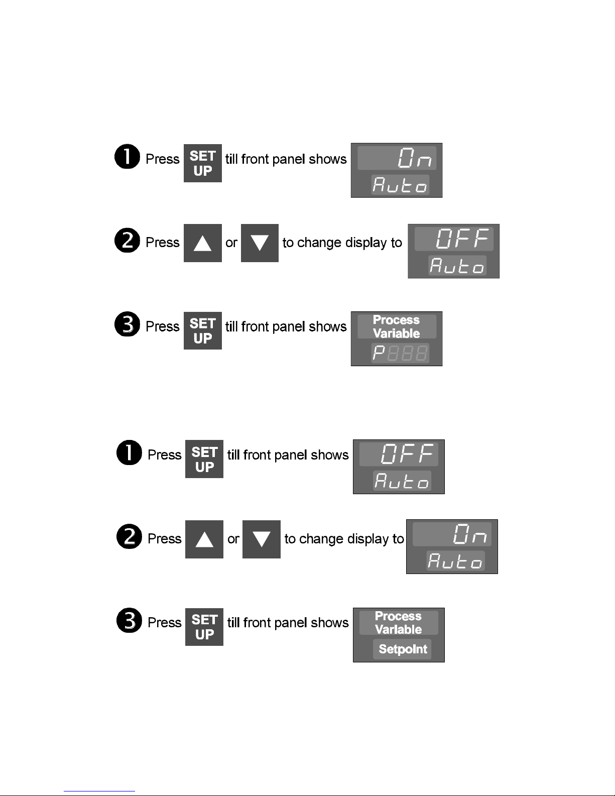
In Base Mode, with no program running or held, Manual Control may be selected as
follows:
The lower display shows the output power in the form Pxxx (xxx is in the range 000% to
100% of maximum output power). This may be adjusted using the Up and Down keys.
To return to automatic control:
1-7
Page 15
2 INSTALLATION
2.1 UNPACKING PROCEDURE
1. Remove the Controller from its packing. The Controller is supplied
with a panel gasket and push-fit fixing strap. Retain the packing for
future use, should it be necessary to transport the Controller to a
different site or to return it to the supplier for repair/testing.
2. Examine the delivered items for damage or deficiencies. If any is
found, notify the carrier immediately.
2.2 PANEL-MOUNTING THE
CONTROLLER
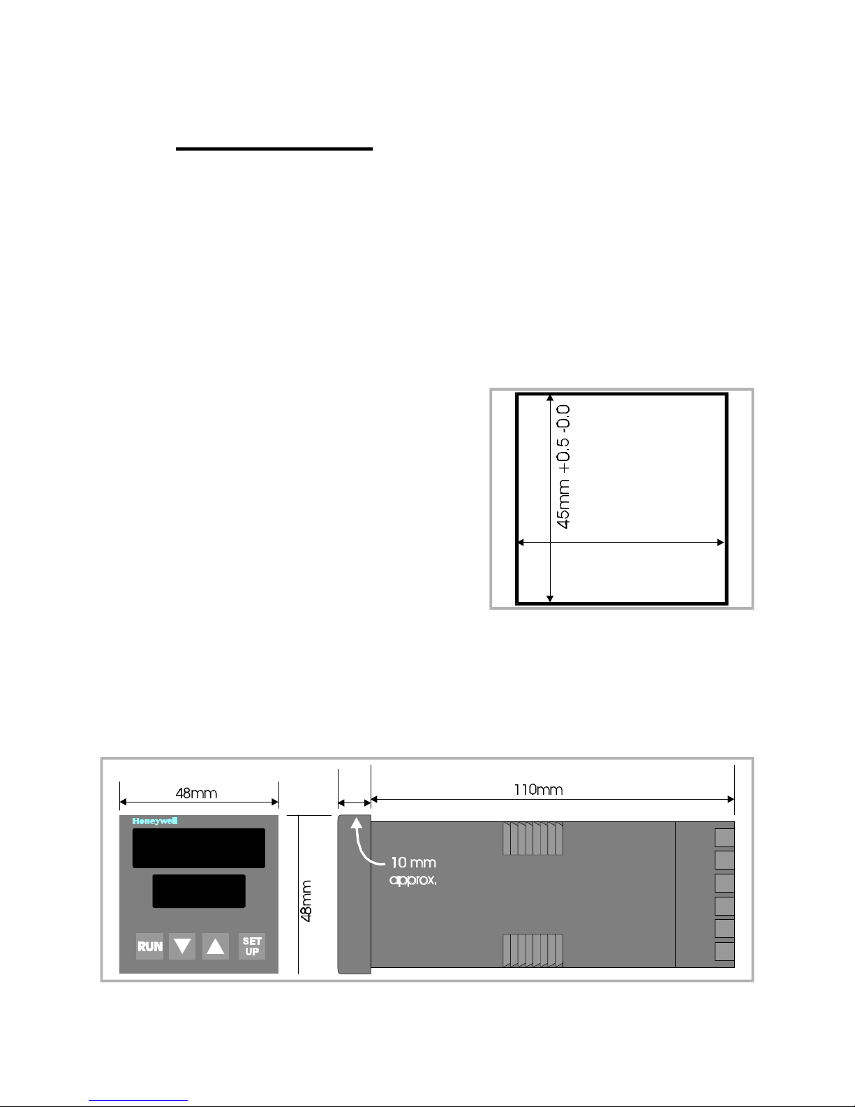
The panel on which the Controller is to be
mounted must be rigid and may be up to 6.0mm
(0.25 inches) thick. The cut-out required for a
single Controller is as shown in Figure 2 -1 .
Several controllers may be installed in a single
cut-out, side-by-side. For n Controllers mounted
side-by-side, the width of the cut-out would be:
Figure 2 -1 Cut-out Dimensions
(48n - 4) millimetres or (3.78n - 0.16) inches.
The Controller Programmer is 110mm deep (measured from the rear face of the front
panel). The front panel is 48mm high and 48mm wide. When panel-mounted, the
front panel projects 10mm from the mounting panel. The main dimensions of the
Controller are shown in Figure 2-2.
45mm +0.5 -0.0
Figure 2-2 Main Dimensions
2-1
Page 16
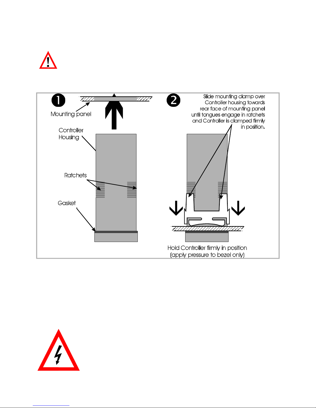
The procedure to panel-mount the Controller Programmer is shown in Figure 2-3.
CAUTION: Do not remove the panel gasket, as this may result in
inadequate clamping of the instrument in the panel.
NOTE: When installing several Programmer Controllers side-by-side in
one cut-out, use the ratchets on the top/bottom faces.
Figure 2 -3 Panel-Mounting the Controller Programmer
Once the Controller is installed in its mounting panel, it may be subsequently
removed from its housing, if necessary, as described in Subsection 7.1.
2.3 CONNECTIONS AND WIRING
The rear terminal connections are illustrated in Figure 2-4.
WARNING ! This instrument is designed for installation in an
enclosure which provides adequate protection aganist electric
shock. All pertinent local regulations should be rigidly observed.
Consideration should be given to prevention of access to the
rear terminals by unauthorised personnel. Disregard for these
instructions may cause injury or death!
2 -2
Page 17
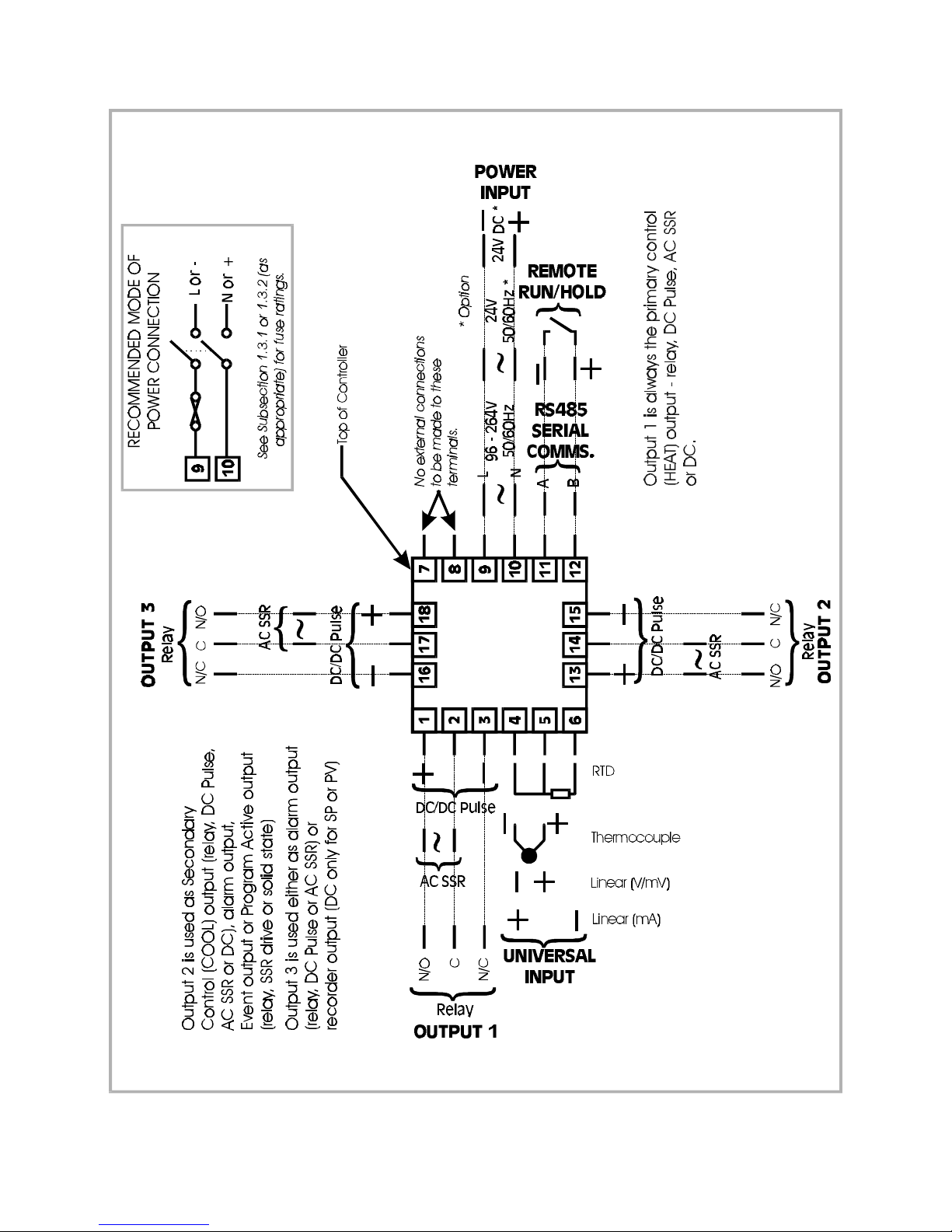
Figure 2 -4 Rear Terminal Connections
2-3
Page 18

2.3.1 Mains (Line) Input
The Controller will operate on 96 - 264V AC 50/60Hz mains (line) supply. The power
consumption is approximately 4 VA. Power should be connected via a two-pole
isolating switch (preferably situated near the equipment) and a 1A fuse.
If the Controller has relay outputs in which the contacts are to carry mains (line)
voltage, it is recommended that the relay contact mains (line) supply should be
switched and fused in a similar manner but should be separate from the Controller
mains (line) supply.
2.3.2 24V (Nominal) AC/DC Supply
The supply connections for the 24V AC/DC option of the Controller are as shown in
Figure 2 -4. Power should be connected via a two-pole isolating switch and a 315mA
slow-blow (anti-surge Type T) fuse.
With the 24V AC/DC supply option fitted, these terminals will accept the following
supply voltage ranges:
24V (nominal) AC 50/60Hz - 20 - 50V
24V (nominal) DC - 22 - 65V
2.3.3 Thermocouple Input
The correct type of thermocouple extension leadwire or compensating cable must
be used for the entire distance between the Controller and the thermocouple,
ensuring that the correct polarity is observed throughout. Joints in the cable should
be avoided, if possible. The Controller’s CJC facility must be enabled (normal
conditions) for this input (see Subsection 6.4).
NOTE: Do not run thermocouple cables adjacent to power-carrying
conductors. If the wiring is run in a conduit, use a separate conduit for the
thermocouple wiring. If the thermocouple is grounded, this must be done at
one point only. If the thermocouple extension lead is shielded, the shield must
be grounded at one point only.
2.3.4 RTD Inputs
The compensating lead should be connected to Terminal 4. For two-wire RTD inputs,
Terminals 4 and 5 should be linked. The extension leads should be of copper and the
resistance of the wires connecting the resistance element should not exceed 5 ohms
per lead (the leads should be of equal resistance).
2-4
Page 19

2.3.5 Linear Inputs
For linear mA input ranges, connection is made to Terminals 4 and 6 in the polarity
shown in Figure 2 -4 . For linear mV and V ranges, connection is made to Terminals 4
and 5 in the polarity shown in Figure 2-4. For details of the linear input ranges
available, refer to Appendix A.
2.3.6 Remote Run/Hold Input
With this option fitted, Terminals 11 and 12 are used for external Run/Hold control of
the currently-selected program; this has an effect identical to that of the front panel
RUN key. These terminals may be connected to (a) the voltage-free contacts of a
switch or relay, or (b) a TTL-compatible voltage. This is an edge-sensitive input for
which the following convention has been adopted:
For TTL input, OFF = logic 1 and ON = logic 0
Fot a voltage=free input, OFF = open and ON = closed
Program control is as follows:
OFF-ON transition: The currently-selected program will run (or will
resume running if it is currently held).
ON-OFF transition: The currently-running program will be held.
NOTE: When this input is used, the front panel RUN key can be used
only to abort a program. Powering-up the Controller Programmer whilst
this input is ON will not cause a program to run. The RS485 Serial
Communications option and the Remote Run/Hold option are mutually
exclusive.
2.3.7 Relay Outputs
The contacts are rated at 2A resistive at 120/240V AC.
2.3.8 DC Pulse Outputs
These outputs produce a time-proportioned non-isolated DC signal (0 - 4.2V nominal
into 1kΩ minimum).
2 -5
Page 20

2.3.9 AC SSR Outputs
These outputs provide up to 1A AC drive with a longer lifetime than an
electromechanical relay. For further details, refer to Appendix A.
2.3.10 DC Outputs
See Appendix A.
2.3.11 RS485 Serial Communications Link
The cable used should be suitable for data transfer at the selected rate (1200, 2400,
4800 or 9600 Baud) over the required distance. Transmitters/receivers conform to the
recommendations in the EIA Standard RS485.
The “A” terminal (Terminal 11) on the Controller should be connected to the “A”
terminal on the master device; the “B” terminal (Terminal 12) on the Controller should
be connected to the “B” terminal on the master device. Where several Controllers
are connected to one master port, the master port transceiver in the active state
should be capable of driving a load of 12k Ω per Controller; the master port
transceiver in the passive state must have pull-up/pull-down resistors of sufficiently low
impedance to ensure that it remains in the quiescent state whilst supplying up to
± 100µA each to the Controller transceivers in the high impedance state.
NOTE: The RS485 Serial Communications option and the Remote
Run/Hold option are mutually exclusive.
2-6
Page 21
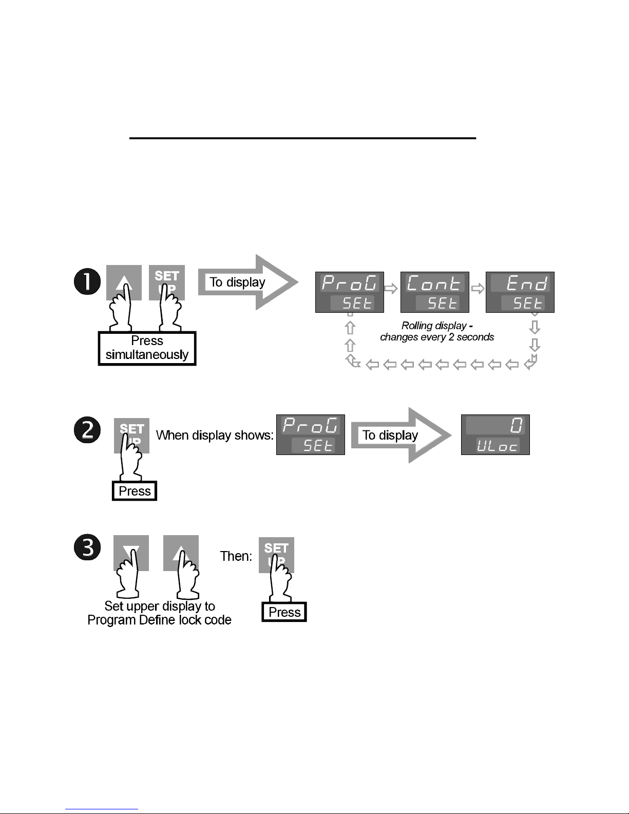
3 PROGRAM DEFINITION MODE -
CREATING/EDITING A PROGRAM
NOTE: Program editing/creation is not possible whilst any program is
running or held.
3.1 ENTRY
In Base Mode, select the required Program Number (see Subsection 1.1 ), then:
NOTE: If the Program Define Mode lock code has been set to 0, pressing the
SET UP key in Step 2 will give direct access to Program Define Mode; no entry
of lock code is required.
Upon entry into Program Define Mode, the first Segment Definition parameter for
Segment 1 of the selected program will be displayed.
3-1
Page 22

3.2 CREATING A PROGRAM
A program is created in two steps:
1. Define the segments of your program; the parameters used depend on
what Program Mode has been configured - Rate Mode (see Subsection 3.2.2 )
or Time Mode (see Subsection 3.2.3 ). The segment definitions determine
whether the selected segment is a Ramp Segment, a Dwell (soak) Segment or
an End Segment.
2. Set the required Program Options (see Subsection 3.2.4). These determine:
(i) The number of cycles performed by the program,
(Ii) The timebase to be used (hours/minutes or minutes/seconds)
(Iii) The width of the Guaranteed Soak Band (if enabled),
(Iv) The state of the event indicator for each segment in the program,
(v) The lock code to be used for subsequent entries into Program Define
Mode.
3.2.1 Basic Guidelines
1. The Controller Programmer may contain up to four programs.
2. Each program may comprise up to 16 segments.
3. Each segment may be:
(a) a Ramp Segment (setpoint changing at a defined rate or between
the initial value and a pre-determined final value over a defined time),
(b) a Dwell Segment (setpoint constant for a defined time,) or
(c) an End Segment (marking the end of the program).
4. A program may contain only one End Segment (the last segment in the
program).
5. If the program comprises 16 segments, Segment 16 is automatically an End
Segment.
3-2
Page 23
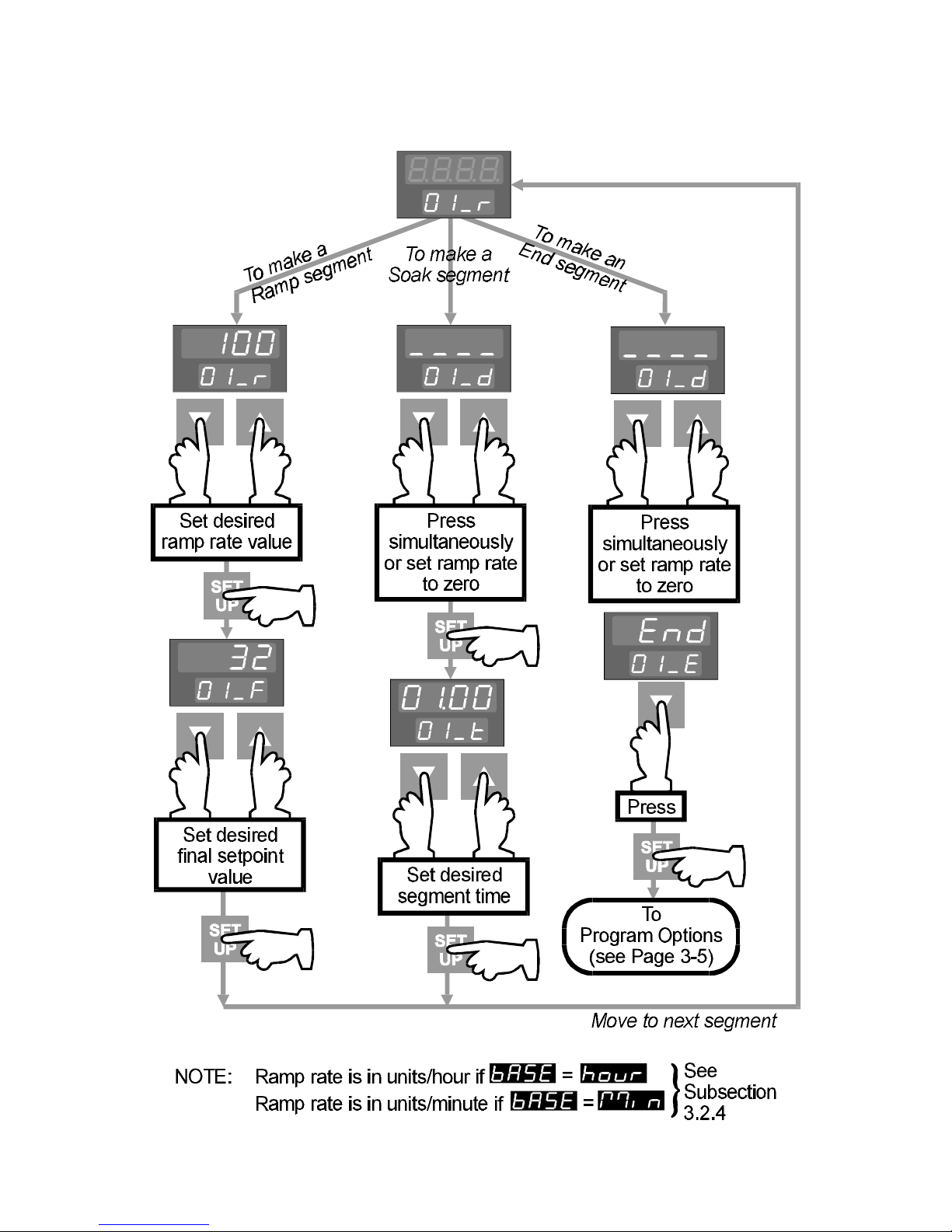
3.2.2 Defining Segm ents - Rate Mode
3-3
Page 24
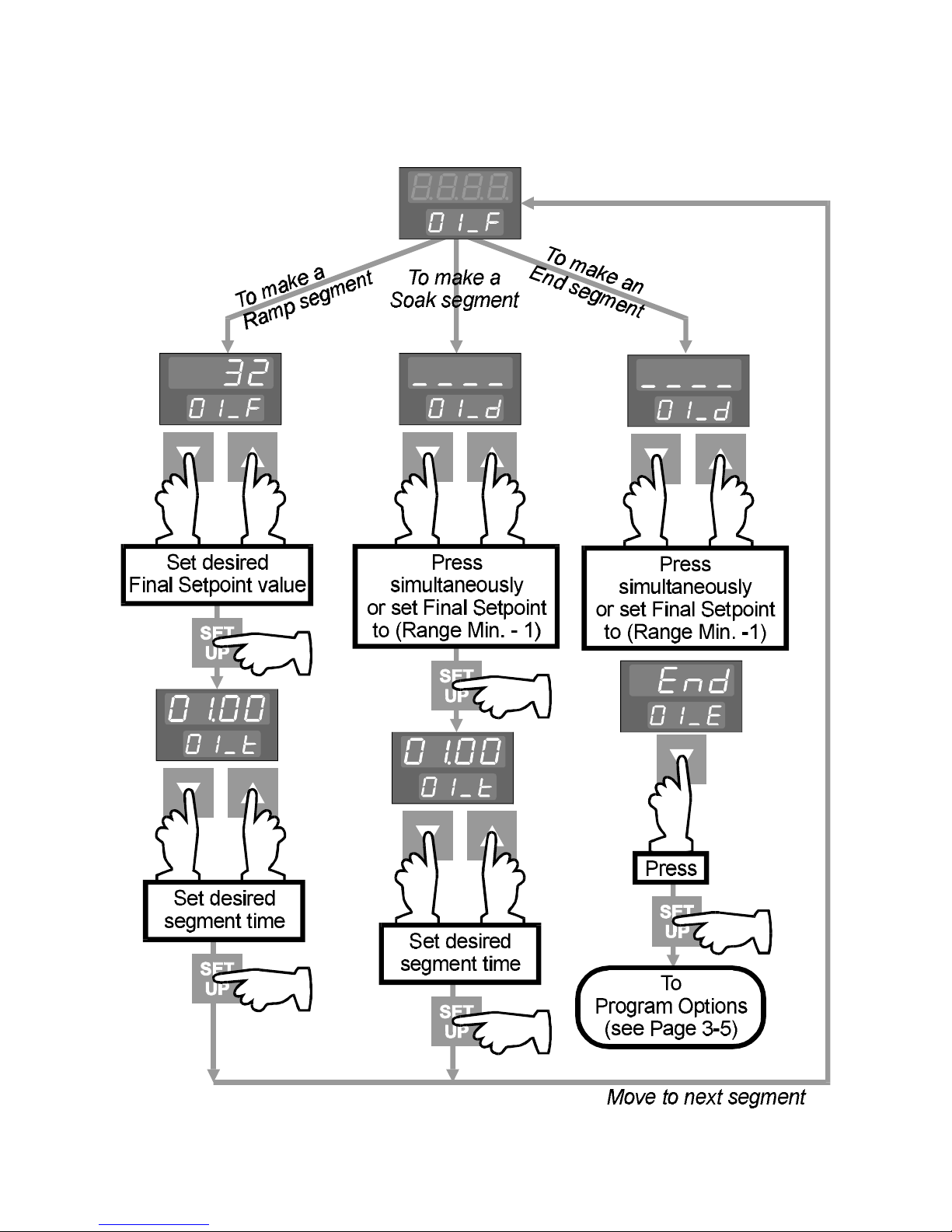
3.2.3 Defining Se gments - Time Mode
3-4
Page 25
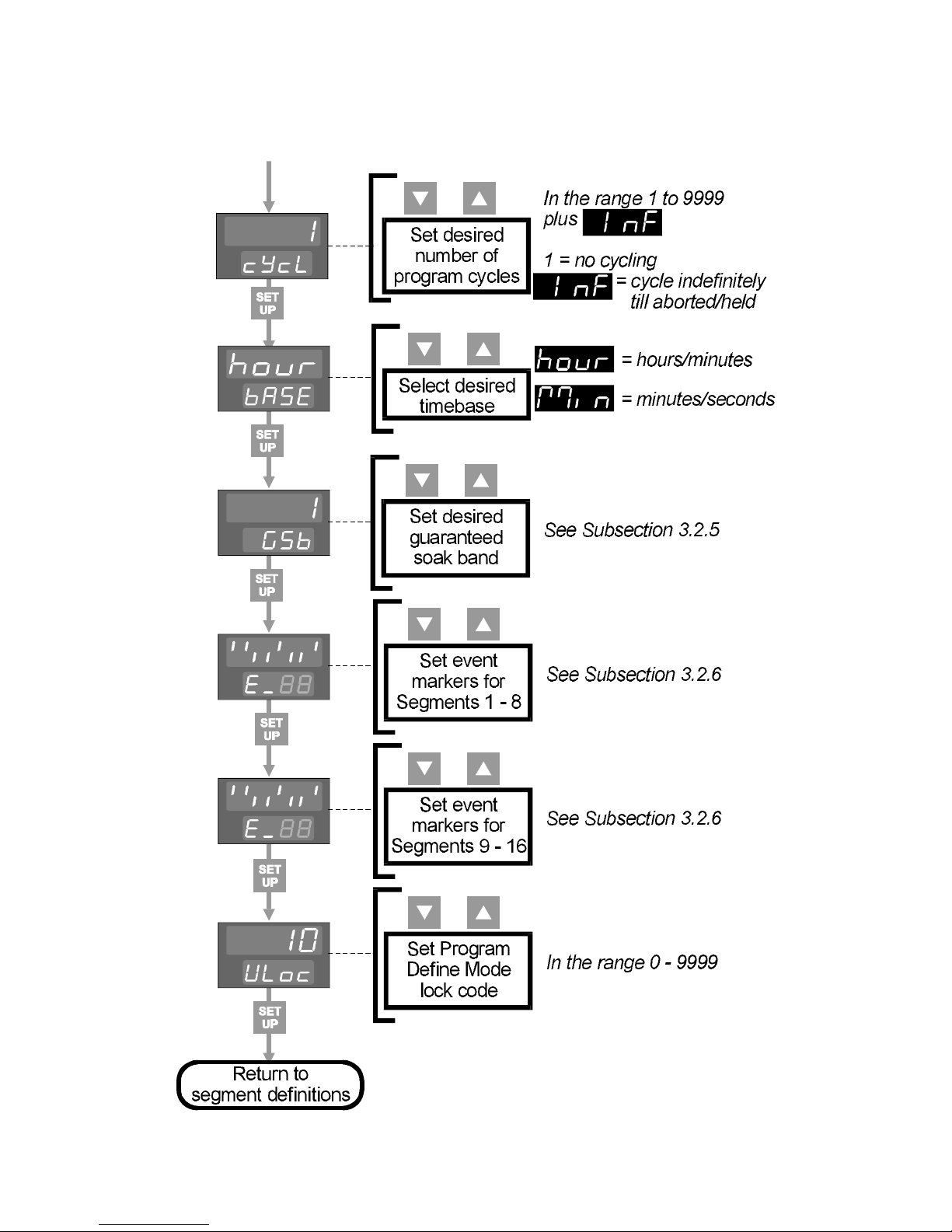
3.2.4 Prog ram O ptions
3-5
Page 26
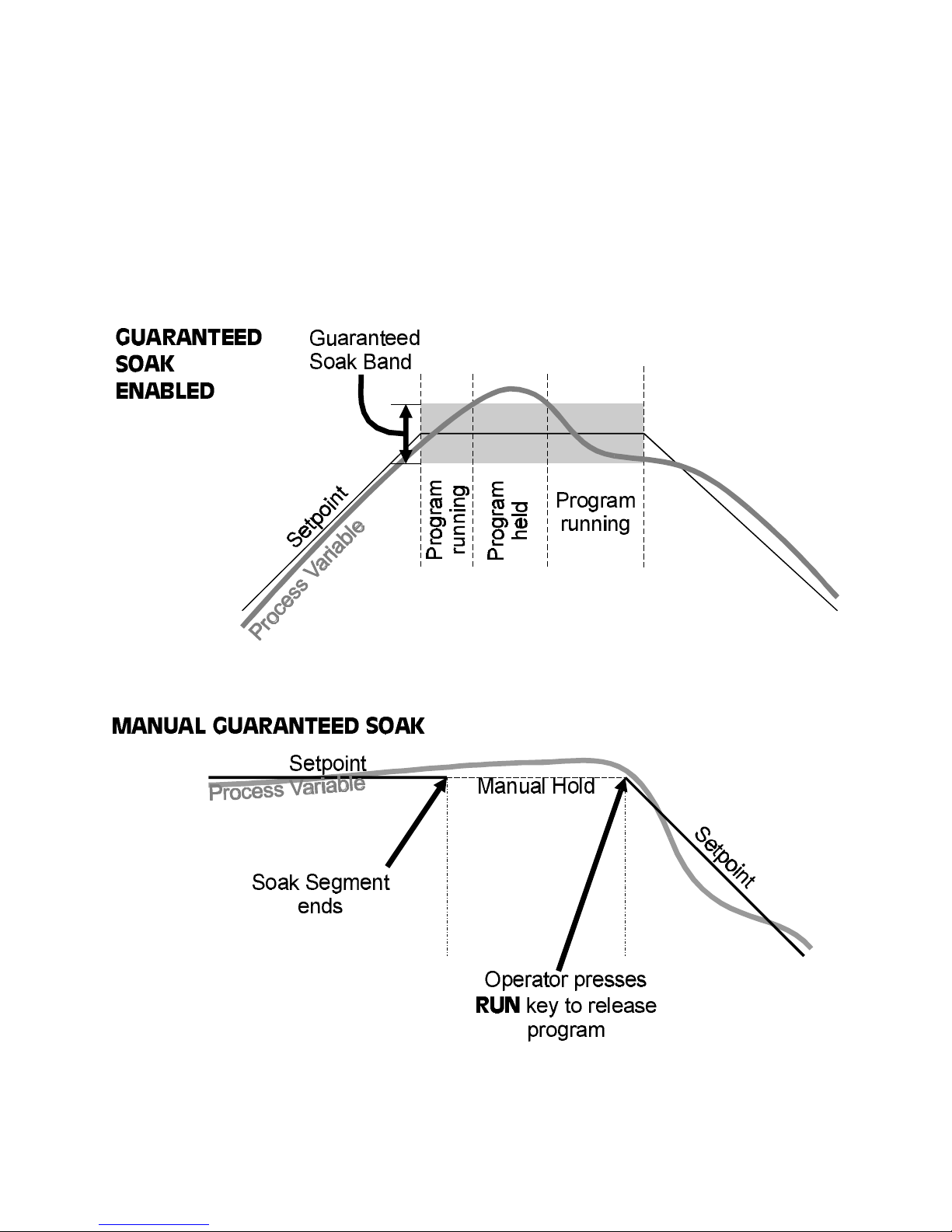
3.2.5 Guaran teed Soak Band
The Guaranteed Soak Band is applicable to sOAK segments only and operates as
follows (depending on whether Guaranteed Soak has been enabled or Manual
Guaranteed Soak has been configured):
3-6
Page 27
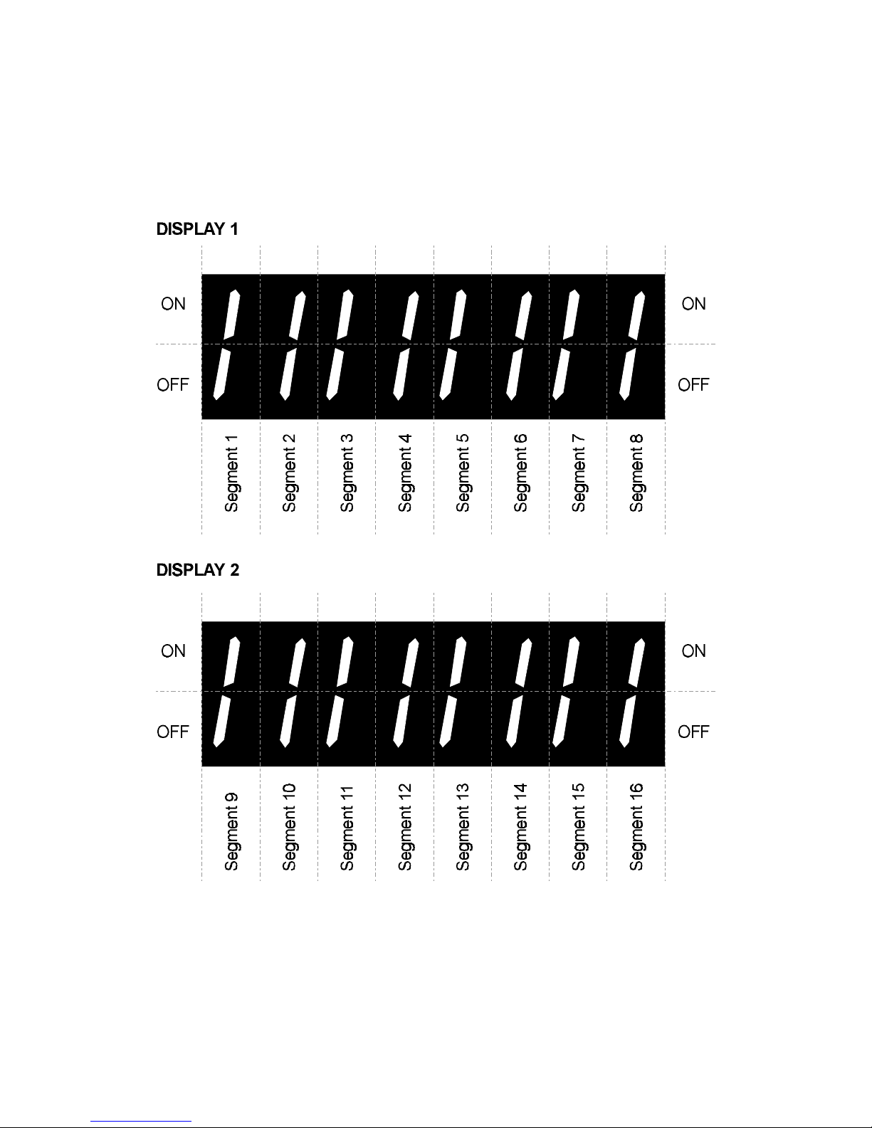
3.2.6 Segment Event Status
For every segment in a program there is an event indicator. This may be set ON or
OFF for that segment. The status for the segments in the currently-selected program
appears in the following form in the upper display:
The first display shows the current event status for Segments 1 - 8 and the second
display shows the current event status for Segments 9 - 16. Each event marker may
be set ON (Up key) or OFF (Down key) in order of segment number. Only the event
indicators for the segments in the program are displayed. If the program has less
than 16 segments (including the End Segment), the non-applicable display positions
are blank; if the program has eight segments or less, the second display is not
3-7
Page 28
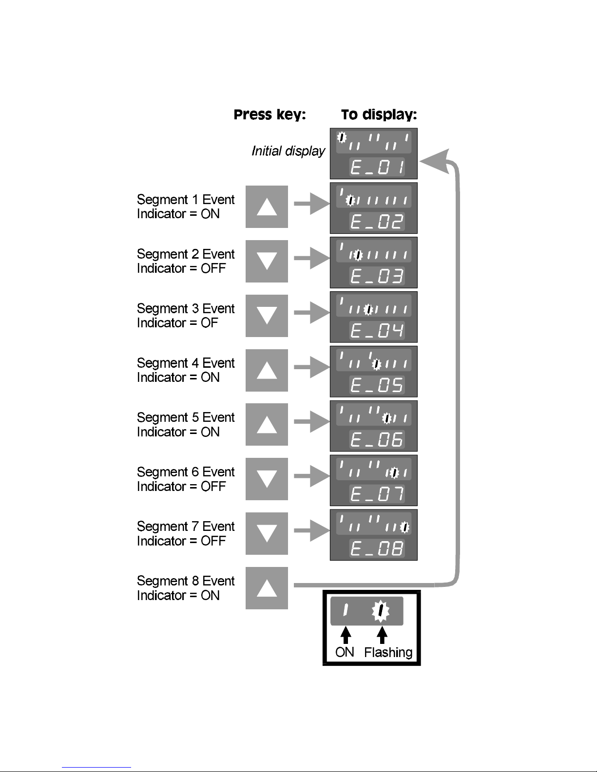
included.. The lower display shows the current segment number. Thus, the key
sequence to define the event markers for Segments 1 - 8 could be:
Pressing the SET UP key would then display the event markers for Segments 9 - 16
(as applicable), which could be defined in a similar manner.
3 -8
Page 29
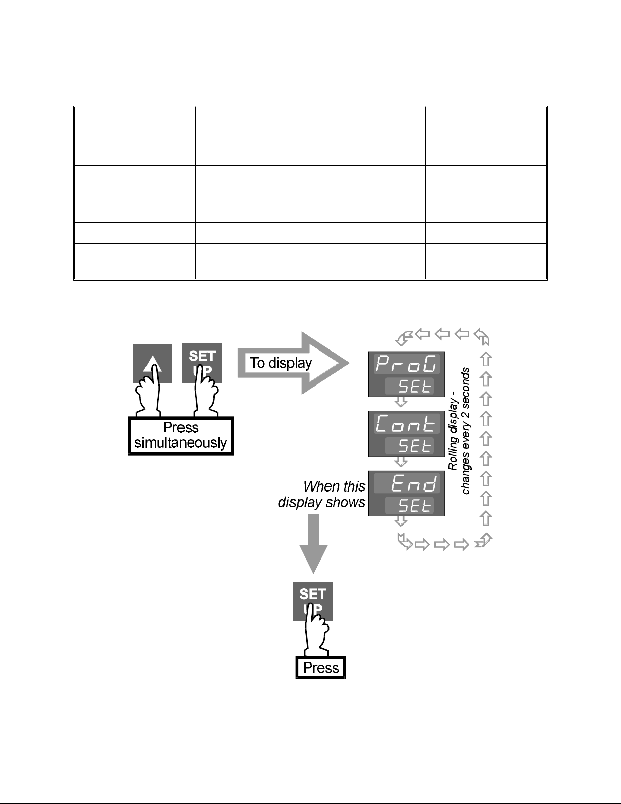
3.3 DEFAULT VALUES AND ADJUSTMENT RANGES
Parameter Range Minimum Range Maximum Default
Ramp Rate 0 = Soak segment
9999, then INF 100
-1 = End segment
Final (End of Ramp)
Range Minimum Range Maximum Range Minimum
Setpoint
Segment Time 00:00 99:59 01:00
Number of Cycles 1 9999 then INF 1
Guaranteed Soak
1 Span plus OFF OFF
Band
3.4 EXIT FROM PROGRAM DEFINE MODE
A return is then made to the normal Base Mode display.
3-9
Page 30
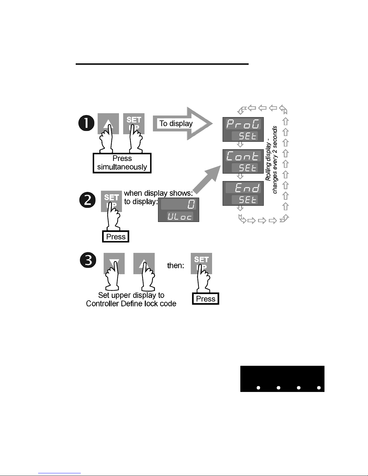
4 CONTROLLER SET-UP MODE
In this mode, the parameters which define the operation of the controller are
defined. Controller Set-Up Mode can be entered (whether or not there is a program
currently running) as follows:
NOTES:
1. If the Controller Set-Up Mode lock code has been set to 0, pressing the SET
UP key in Step 2 will give direct access to Controller Set-Up Mode; no entry of
lock code is required.
2. If the upper display initially shows all decimal points
illuminated (see right), one or more configuration
parameters have been altered and, as a
consequence, all ControllerSet Up Mode parameters
have been automatically set to their default
values/settings. To clear this display, simply alter the value/setting of any
Controller Set Up Mode parameter.
4-1
Page 31
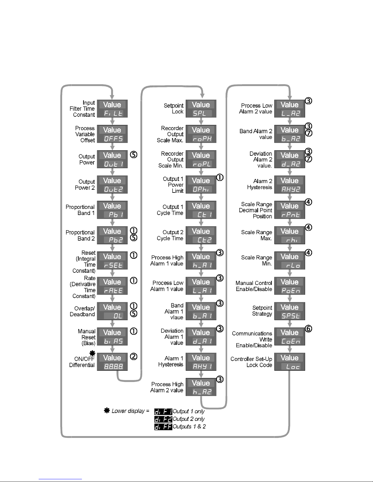
Upon entry into Controller Set-Up Mode, the first in a sequence of controller
parameters will be displayed. The operator may then step through the parameter
sequence using the SET UP key, adjusting the setting/value of each displayed
parameter using the Up/Down keys. The parameter sequence is as follows:
4-2
Page 32

NOTES
1. Not operative if Proportional Band = 0.
2. Switching differential for ON/OFF control output.
3. Optional; only one legend will appear for each alarm.
4. Only applicable if a DC linear input is fitted.
5. Only applicable if Output 2 is fitted as a secondary control (COOL)
output.
6. Applicable only if the Communications Option is fitted.
7. When a program is running, respective to program setpoint.
4.1 PARAMETER DETAILS
Parameter Function Adjustment Range Default value
Input Filter Time
Constant
Process Variable
Offset
Output Power 1 Current Output 1 power level 0 to 100% Read only
Output Power 2 Current Output 2 power level 0 to 100% Read only
Proportional
Band 1 (PB1)
Proportional
Band 2 (PB2)
Reset (Integral
Time Constant)
Rate (Derivative
Time Constant)
Filter removes extraneous impulses from
the process variable input
Modifies actual process variable (PV)
value:
Offset PV + actual PV
= PV value used
Portion of input span in which Output 1
power level is proportional to the
(offset) process variable value (see
Figure 4-1).
Portion of input span in which Output 2
power level is proportional to the
(offset) process variable value (see
Figure 4-1).
Integral time constant 1sec. to 99min. 59
Derivative time constant 00 secs. to 99 mins. 59
OFF, 0.5 to 100.0
seconds in 0.5 second
increments
±input span of
Controller
0.0 to 999.9% of input
span
0.0 to 999.9% of input
span
secs. and OFF
secs.
2.0 seconds
0
10.0%
10.0%
5 mins. 00
secs.
1 min. 15
secs.
Overlap/
Deadband
Manual Reset
(Bias)
4-3
Portion of proportional band (PB1 +
PB2) in which both outputs are active
(overlap) or neither output is active
(deadband) - see Figure 4-1).
Bias applied to output power,
expressed as a percentage of output
power.
− 20% to +20% of
(Proportional Band 1 +
Proportional Band 2)
0% to 100% (Output 1
only);
−100% to +100%
(Output 1 & Output 2)
0%
25%
Page 33
Parameter Function Adjustment Range Default value
ON/OFF
Differential
Switching differential for one output or
both outputs set to ON/OFF control (PB1,
PB2 or both = 0) - see Figure 4-1.
Setpoint Lock Enables/disables setpoint (SP)
adjustment in Base Mode.
Recorder Output
Scale Maximum
Process variable or setpoint value (as
applicable) for which the recorder
output is a maximum
Recorder Output
Scale Minimum
Process variable or setpoint value (as
applicable) for which the recorder
output is a minimum
Output 1 Power
Limit
Output 1 Cycle
Time
Output 2 Cycle
Time
Limits Output 1 power level (to protect
the process)
Limits the frequency of operation of
output relay to maximise relay life
Limits the frequency of operation of
output relay to maximise relay life
0.1% to 10.0% of
input span
OFF - SP adjustable
ON - SP not adjustable
−1999 to 9999
(decimal point
position as for input
range)
−1999 to 9999
(decimal point
position as for input
range)
0% to 100% of full
power
0.5, 1, 2, 4, 8, 16, 32,
64, 128, 256 or 512
secs.
0.5, 1, 2, 4, 8, 16, 32,
64, 128, 256 or 512
secs.
0.5%
OFF
Input Range
Maximum
Input Range
Minimum
100%
32 secs.
32 secs.
Process High
Alarm 1
If Alarm 1 is a Process High Alarm, the
value of the process variable at or
above which Alarm 1 will be active (see
Figure 4-2)
Process Low
Alarm 1
If Alarm 1 is a Process Low Alarm, the
value of the process variable at or
below which Alarm 1 will be active (see
Figure 4-2)
Band Alarm 1 If Alarm 1 is a Band Alarm, the band of
process variable values, centred on the
(program) setpoint, outside which the
process variable will cause this alarm to
be active (see Figure 4-2)
Deviation
Alarm 1
If Alarm 1 is a Deviation Alarm, gives a
value above (positive value) or below
(negative value) the (program) setpoint.
If the process variable deviates from
the setpoint by a marging greater than
this value, the alarm becomes active
(see Figure 4-2)
Alarm 1
Hysteresis
Defines a hysteresis band on the “safe”
side of the Alarm 1 value
Input Range Minimum
to Input Range
Input Range
Maximum
Maximum
Input Range Minimum
to Input Range
Input Range
Minimum
Maximum
0 to input span from
5 units
(program) setpoint
± input span from
5 units
(program) setpoint
1 to 250 units 1 unit
4-4
Page 34
Parameter Function Adjustment Range Default value
Process High
Alarm 2
If Alarm 2 is a Process High Alarm, the
value of the process variable at or
above which Alarm 2 will be active
(see Figure 4-2)
Process Low
Alarm 2
If Alarm 2 is a Process Low Alarm, the
value of the process variable at or
below which Alarm 2 will be active
(see Figure 4-2)
Band Alarm 2 If Alarm 2 is a Band Alarm, the band
of process variable values, centred
on the (program) setpoint, outside
which the process variable will cause
this alarm to be active (see Figure
4-2)
Deviation
Alarm 2
If Alarm 2 is a Deviation Alarm, gives
a value above (positive value) or
below (negative value) the (program)
setpoint. If the process variable
deviates from the setpoint by a
marging greater than this value, the
alarm becomes active (see Figure
4-2)
Alarm 2 Hysteresis Defines a hysteresis band on the
“safe” side of the Alarm 2 value
Input Range Minimum
to Input Range
Input Range
Maximum
Maximum
Input Range Minimum
to Input Range
Input Range
Minimum
Maximum
0 to input span from
5 units
(program) setpoint
±input span from
5 units
(program) setpoint
1 to 250 units 1 unit
Scale Range
Decimal Point
For linear inputs only, defines the
decimal point position
Position
Scale Range
Maximum
For linear inputs only, defines the
scaled input value when the process
variable input is at its maximum value
Scale Range
Minimum
For linear inputs only, defines the
scaled input value when the process
variable input is at its minimum value
Manual Control
Enable/Disable
Setpoint Strategy Determines whether or not the
setpoint is adjustable in the normal
Base Mode display
Communications
Enable/Disable
Enables/disables changing of
parameter values via the
communications link
Controller Set-Up
Mode Lock Code
Defines the four-digit code required
to enter the Controller Set-Up Mode
0 (xxxx), 1 (xxx.x), 2
1 (xxx.x)
(xx.xx) or 3 (x.xxx)
−1999 to 9999
−1999 to 9999
0 (Disabled) or
1000
0000
0 (Disabled)
1 (Enabled)
0 = not adjustable,
1
1 = adjustable
0 (disabled) or
1 (Enabled)
1 (Enabled)
0 to 9999 10
4-5
Page 35
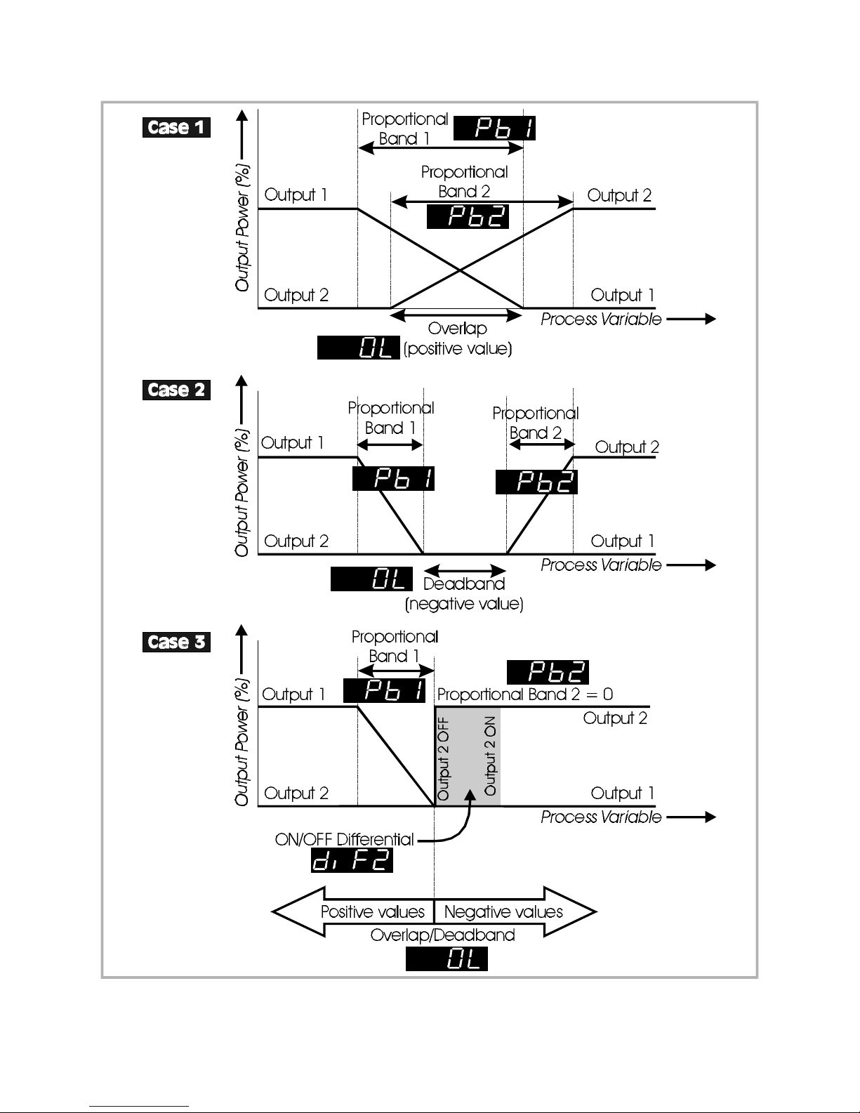
Figure 4 -1 Proportional Band and O verlap/Dead band
4-6
Page 36
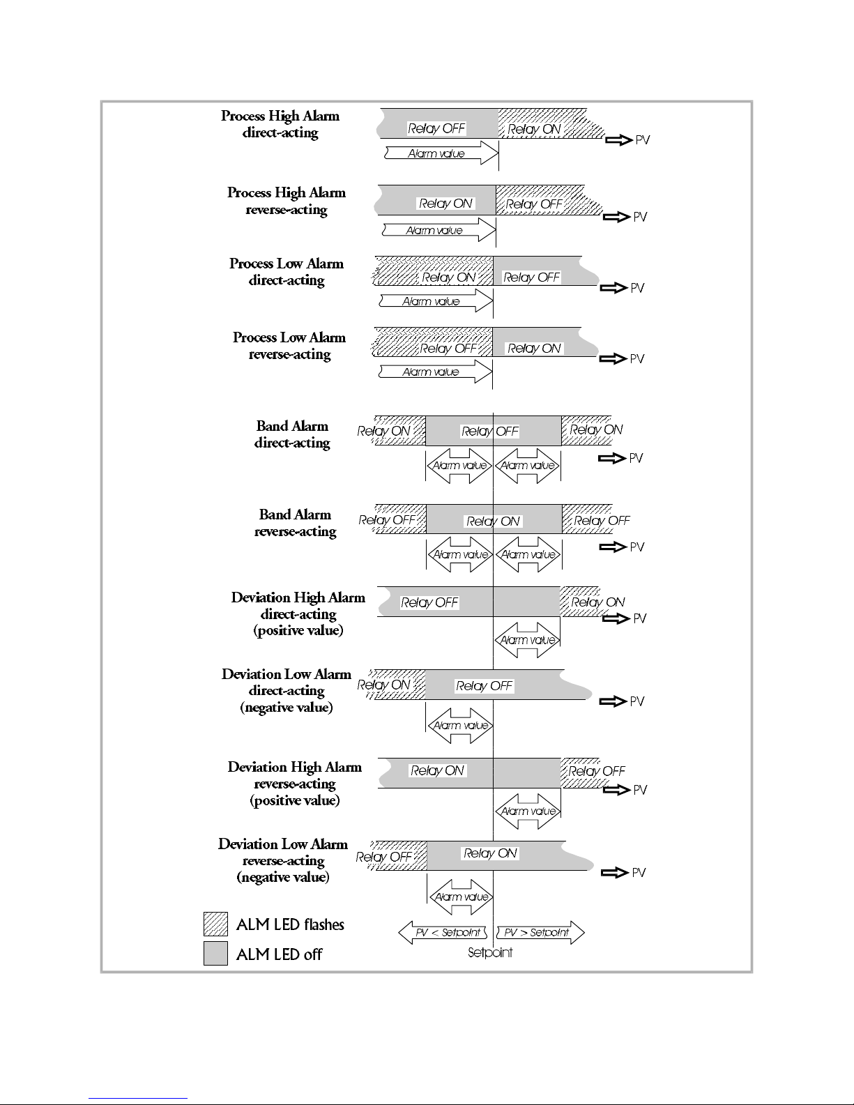
4-7
Figure 4-2 Alarm Operation
Page 37
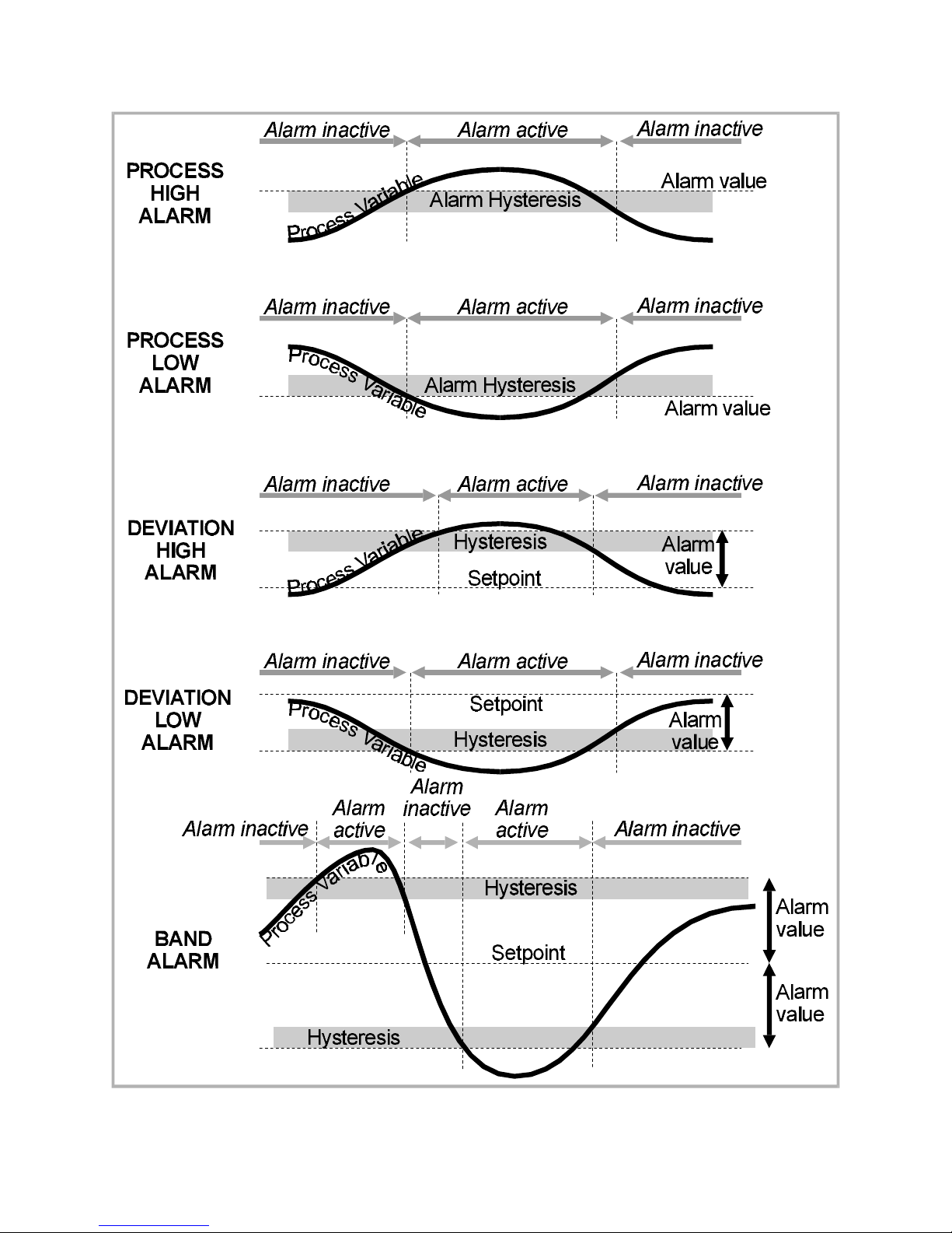
Figure 4-3 Alarm Hysteresis Operation
4 -8
Page 38
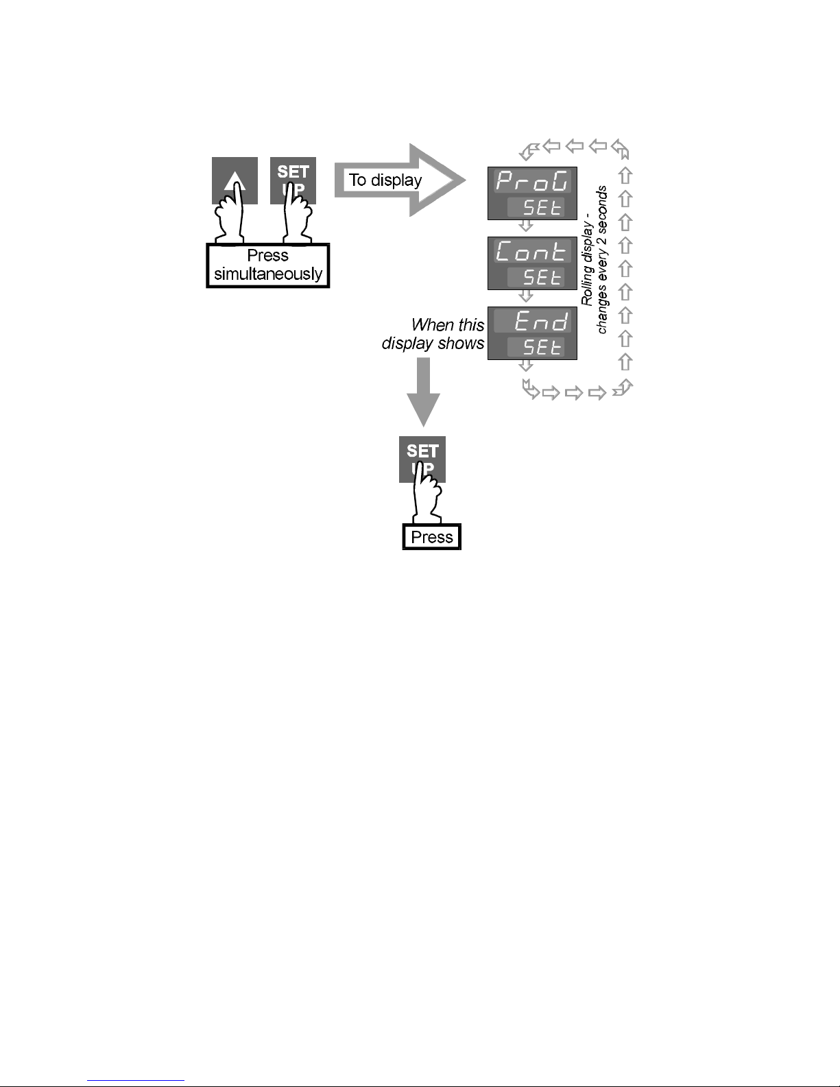
4.2 EXIT FROM CONTROLLER SET-UP MODE
A return will then be made to the normal Base Mode display.
4-9
Page 39

5 MODBUS COMMUNICATIONS
5.1 INTRODUCTION
This Section specifies the MODBUS communications protocol as implemented on the
Controller Programmer.
Certain restrictions have been imposed upon this implementation:
(i) Baud rates may be set to 1200, 2400, 4800 and 9600 only
(ii) Support for multi-parameter Writes is limited to support of the Multi-word
Write Function (Number 16) but will permit writing of one parameter only per
message
(iii) The multi-parameter Read function supports a maximum of 10 parameters
in one message.
5.2 MODBUS FUNCTIONS SUPPORTED
In the following list, the original Gould MODBUS function names have been used,
followed by the JBUS names in italics, where such an equivalence exists. The
MODBUS Function number follows the names.
A Read Coil Status (Read n Bits) 01/02
B Read Holding Registers (Read n Words) 03/04
C Force Single Coil (Write 1 Bit) 05
D Preset Single Register (Write 1 Word) 06
E Loopback Diagnostic Test 08
F Preset Multiple Registers (Write n Words) 16
The instrument will identify itself in reply to a Read Holding Registers message which
enquires the values of parameter numbers 121 & 122, as specified in the CNOMO
documentation, and MODBUS Function 17 (Report Slave ID) will not be supported.
5-1
Page 40
5.3 MESSAGE FORMATS
The first character of every message is an instrument address. The valid range of
such an address is 0 to 255. The second character is always the Function Number.
The contents of the remainder of the message depends upon the function number.
In most cases the instrument is required to reply by echoing the address and function
number, together with an echo of all or part of the message received (in the case of
a request to write a value or carry out a command) or the information requested (in
the case of a read parameter operation). Broadcast Messages (to which the
controller responds by taking some action without sending back a reply) are
supported at instrument address zero. Commands which can be broadcast are
marked with the symbol B.
Data is transmitted as eight-bit binary bytes with 1 start bit, 1 stop bit and optional
parity checking (None, Even or Odd). A message is terminated solely by a delay of
more than three character lengths at the given Baud Rate, and any character
received after such a delay is treated as a potential address at the start of a new
message.
The following individual message formats apply. Since only the RTU form of the
protocol is being supported, each message is followed by a two-byte CRC16.
Details of how the checksum must be calculated are given at the end of this section.
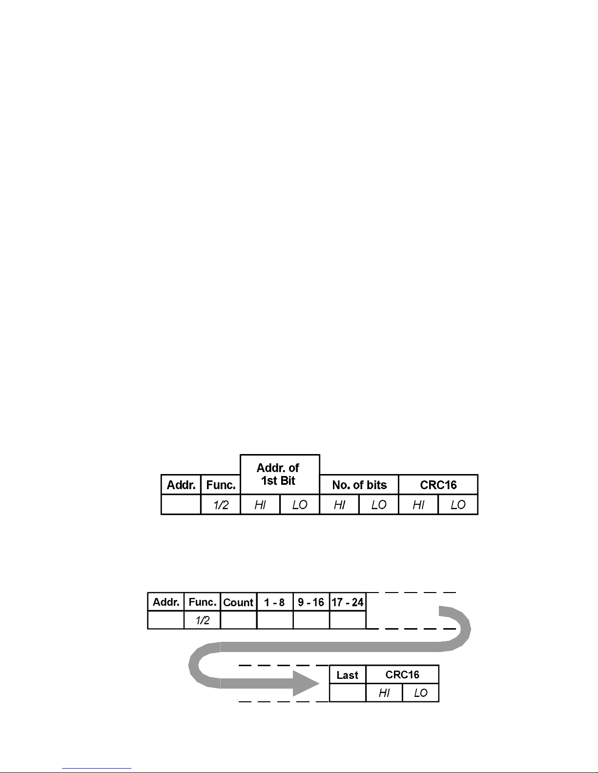
A. Read Coil Status (Read n Bits) 01/02
The message sent to the controller will consist of 8 bytes, as follows:
The normal reply will echo the first two characters of the message received, and will
then contain a single-byte data byte count, which will not include itself or the CRC.
For this message, there will be one byte of data per eight bits-worth of information
requested, with the LSbit of the first data byte transmitted depicting the state of the
lowest-numbered bit required.
5 -2
Page 41
This function will be used largely to report controller status information, and so a bit
set to 1 indicates that the corresponding feature is currently enabled/active, and a
bit reset to 0 indicates the opposite.
If an exact multiple of eight bits is not requested, the data is padded with trailing
zeros to preserve the 8-bit format. After the data has been transmitted, the CRC16
value is sent.
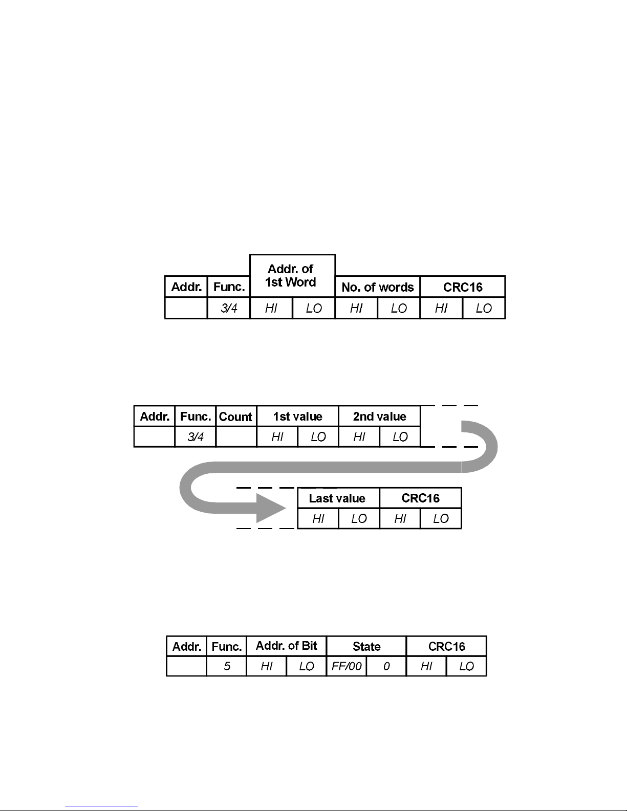
B. Read Holding Registers (Read n Words) 03/04
The message sent to the controller to obtain the value of one or more registers is an
eight-byte message as follows:
The reply sent by the controller echoes the first 2 characters received and then
contains a single-byte data byte count, the value of which does not include either
itself or the CRC value to be sent. For this message, the count equals the number of
parameters read times two. Following the byte count, that number of parameter
values are transmitted, MSB first, followed by the CRC16.
C. Force Single Coil (Write 1 Bit) 05 B
The message received by the controller is 8 bytes long, consisting of the standard
preamble and the address of the bit to force, followed by a two-byte word whose
MSB contains the desired truth value of the bit expressed as 0xFF (TRUE) or 0x00
(FALSE).
Generally, this function will be used to control such features as Auto/Manual and
Tuning. The normal reply sent by the controller will be a byte-for-byte echo of the
message received.
5-3
Page 42
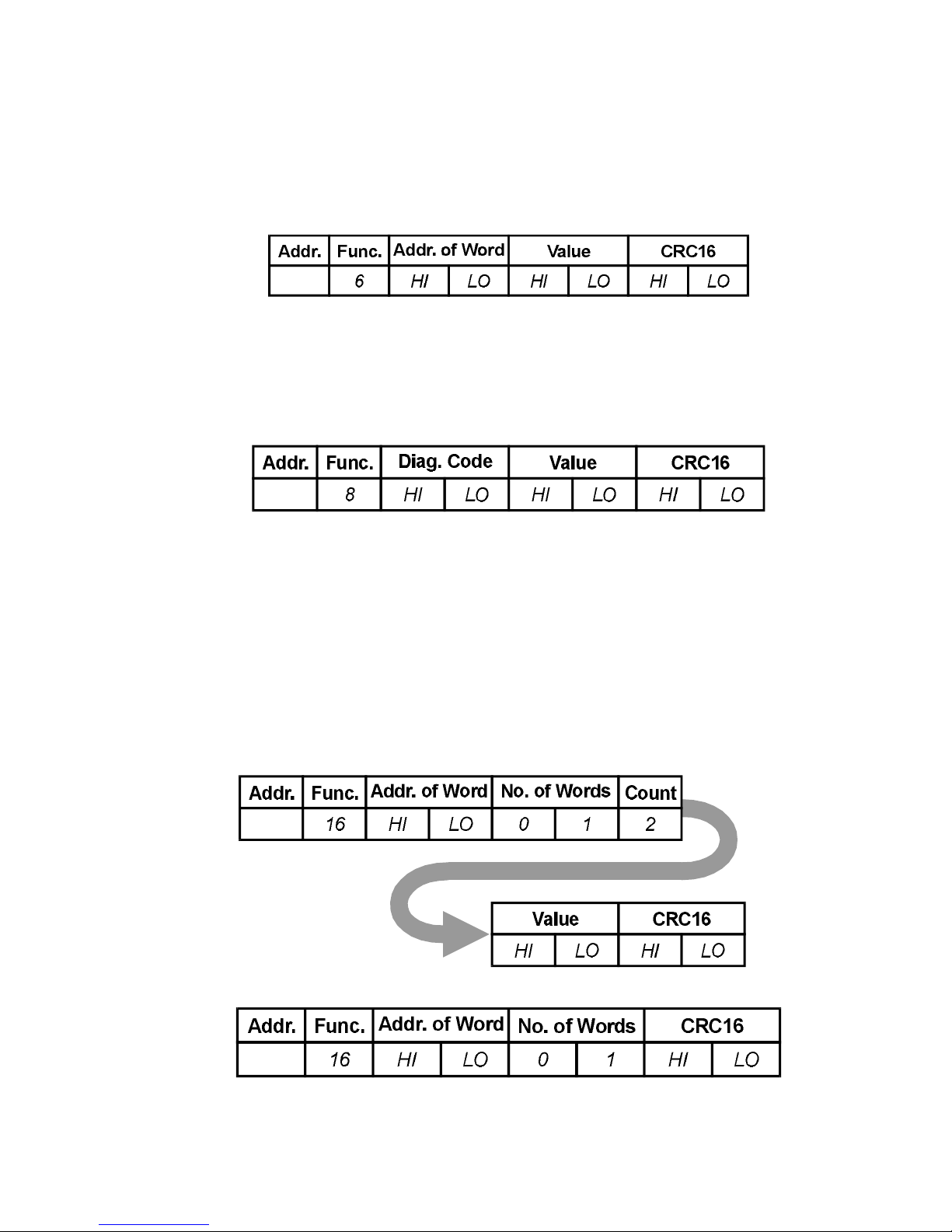
D. Preset Single Register (Write 1 Word) 06 B
The message sent to the controller consists of 8 bytes: the address and function
number as usual, the address of the parameter to be written, and the two-byte value
to which the parameter will be set, and finally the CRC16.
The normal response is to echo the message in its entirety.
E. Loopback Diagnostic Test 08
The controller is sent an 8 byte message consisting of the usual preamble, a two-byte
diagnostic code, and two bytes of data, followed by the CRC16.
Full MODBUS support in this area is not appropriate - consequently, the only
Diagnostic Code supported is code 00. In response to the message, the controller
must echo the message received exactly.
F. Preset Multiple Registers (Write n Words) 16 B
This message consists of eleven bytes. Only one parameter may be written at a time,
even though this function number is supported. The preamble is followed by the
address of the parameter to be written, and then a two-byte word count (always set
to 1) and a single-byte byte count (always set to 2). Finally, the value to be written is
followed by the CRC16.
The controller normally responds with a eight-byte reply, as follows:
5-4
Page 43
G. Error and Exception Responses
If the controller receives a message which contains a corrupted character (parity
check fail, framing error etc), or if the CRC16 check fails, the controller ignores the
message. If the message is otherwise syntactically flawed (e.g. the byte count or
word count is incorrect) the controller will also not reply.
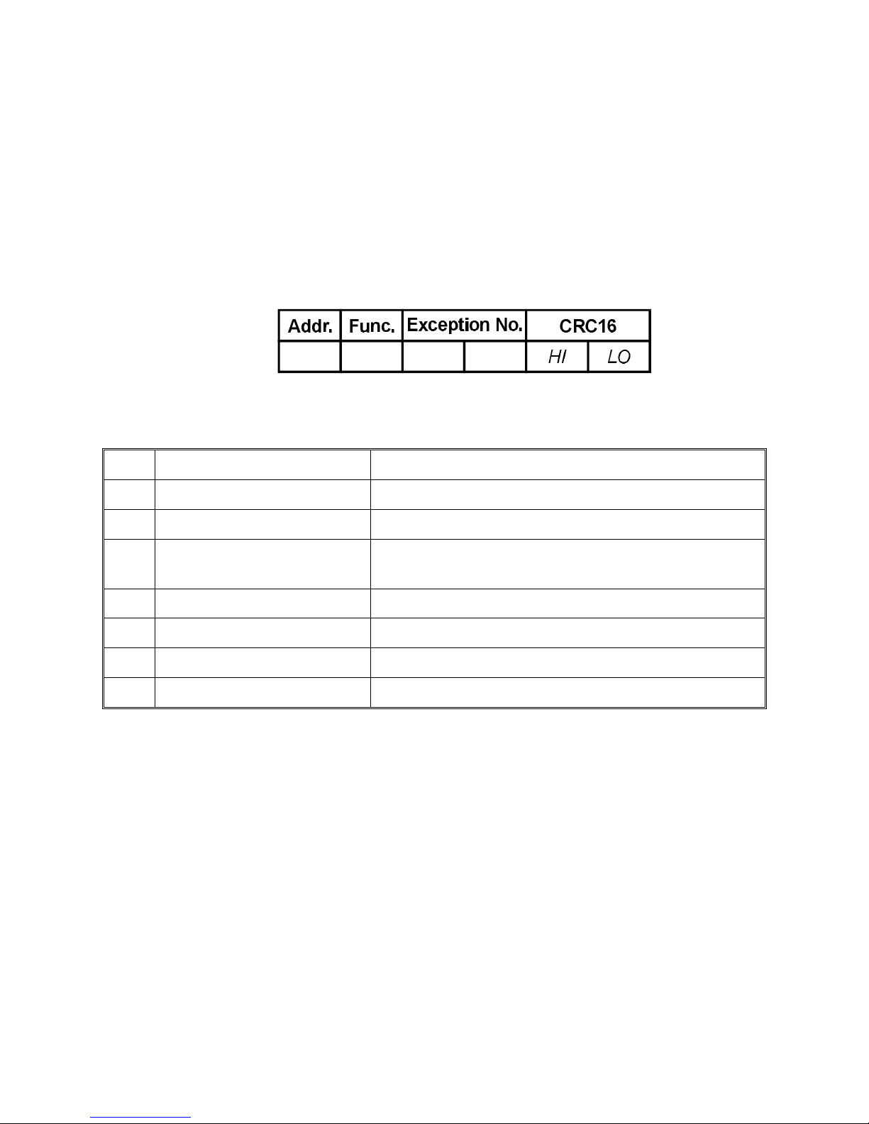
However, if the controller receives a syntactically correct message which nonetheless
contains an illegal value, it will send an exception response, consisting of five bytes
as follows:
The Function Number field consists of the function number contained in the message
which caused the error, with its top bit set (i.e. function 3 becomes 0x83), and the
Exception Number is one of the codes contained in the following table:
Code Name Cause
1 ILLEGAL FUNCTION Function Number out of range
2 ILLEGAL DATA ADDRESS Parameter ID out of range or not supported
3 ILLEGAL DATA VALUE Attempt to write invalid data/action not carried
out
4 DEVICE FAILURE N/A
5 ACKNOWLEDGE N/A
6 BUSY N/A
7 NEGATIVE ACKNOWLEDGE N/A
H. CRC16 Calculation
This is a 16-bit cyclic redundancy checksum. It is calculated in accordance with a
formula which involves recursive division of the data by a polynomial, with the input
to each division being the remainder of the results of the previous one.
The formula specifies that input is treated as a continuous bit-stream binary number,
with the most significant bit being transmitted first. However, the transmitting device
sends the least significant bit first.
According to the formula, the dividing polynomial is 216 + 215 + 22 + 1 (Hex 18005),
but this is modified in two ways:
5-5
Page 44
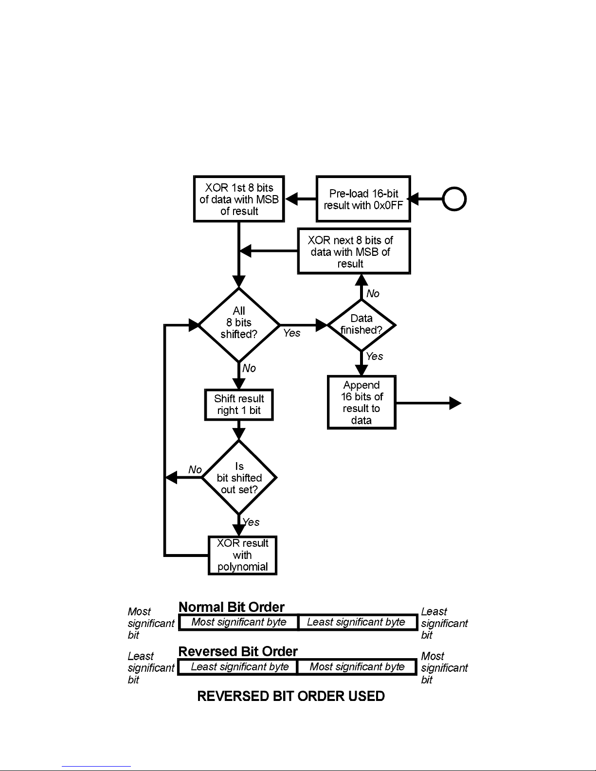
i. Because the bit-order is reversed, the binary pattern is reversed also,
making the MSB the rightmost bit, and
ii. Because only the remainder is of interest, the MSB (the right-most bit) may
be discarded.
This means the polynomial has the value Hex A001. The CRC algorithm is as follows:
5-6
Page 45

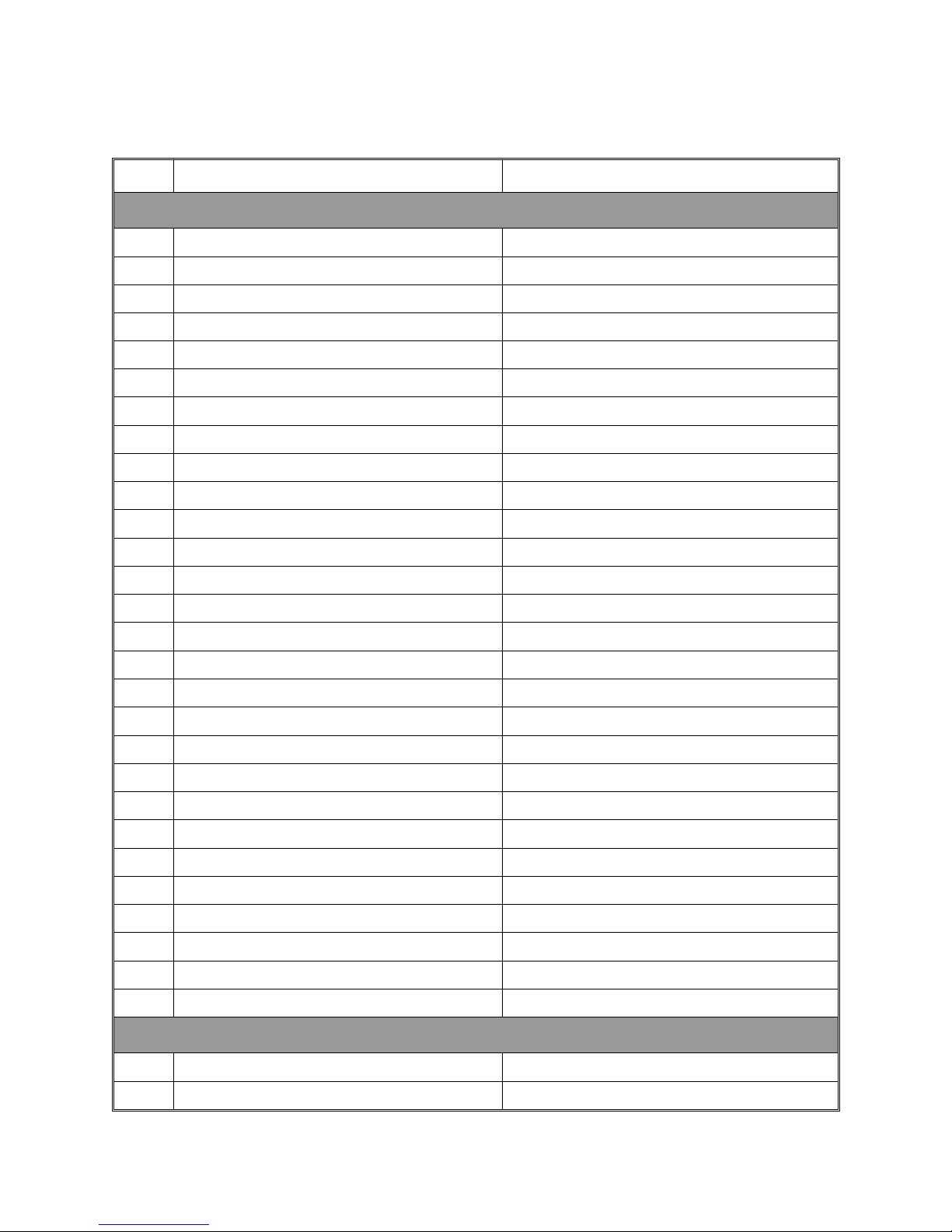
5.4 PARAMETER NUMBERS
The parameter numbering system, in order to conform to the CNOMO standard, splits
parameters into BITS and WORDS and numbers each group independently.
A. Bit Parameters (Controller Status Byte)
There are a maximum of sixteen of these:
No. Parameter Notes
1 Communications Write Status Read only - 1 = enabled, 0 = disabled
2 Auto/Manual Control 1 = Manual, 0 = Auto
3 RaPID Tuning Status 1 = active, 0 = inactive
4 Pre-Tune Status 1 = active, 0 = inactive
5 Alarm 1 Status Read only - 1 = active, 0 = inactive
6 Alarm 2 Status Read only - 1 = active, 0 = inactive
7 Reserved
8 Reserved
9 Reserved
10 Reserved
11 Reserved
12 Reserved
13 Reserved
14 Reserved
15 Reserved
16 Reserved
5-7
Page 46
B. Word Parameters
No. Parameter Notes
Controller Parameters
1 Process Variable Read only
2 Setpoint Current setpoint, if ramping
3 Output Power Read only, unless in Manual Control
4 Arithmetic Deviation Read only
5 Proportional Band 2
6 Proportional Band 1
7 Controller Status
8 Reset
9 Rate
10 Output 1 Cycle Time
11 Scale Range Low Read only if non-linear input
12 Scale Range High Read only if non-linear input
13 Alarm 1 value
14 Alarm 2 value
15 Manual Reset
16 Overlap/Deadband
17 ON/OFF Differential
18 Decimal Point Position Read only if non-linear input
19 Output 2 Cycle Time
20 Output 1 Power Limit
21 Setpoint Lock 0 = Off, 1 = On
22 Reserved
23 Filter Time Constant
24 Process Variable Offset
25 Recorder Output Max.
26 Recorder Output Min.
27 Alarm 1 Hysteresis
28 Alarm 2 Hysteresis
Program Parameters
29 Segment Mode 0 = Rate, 1 = Time
30 Profiler Status Read only - see Subsection 5.5.
5-8
Page 47
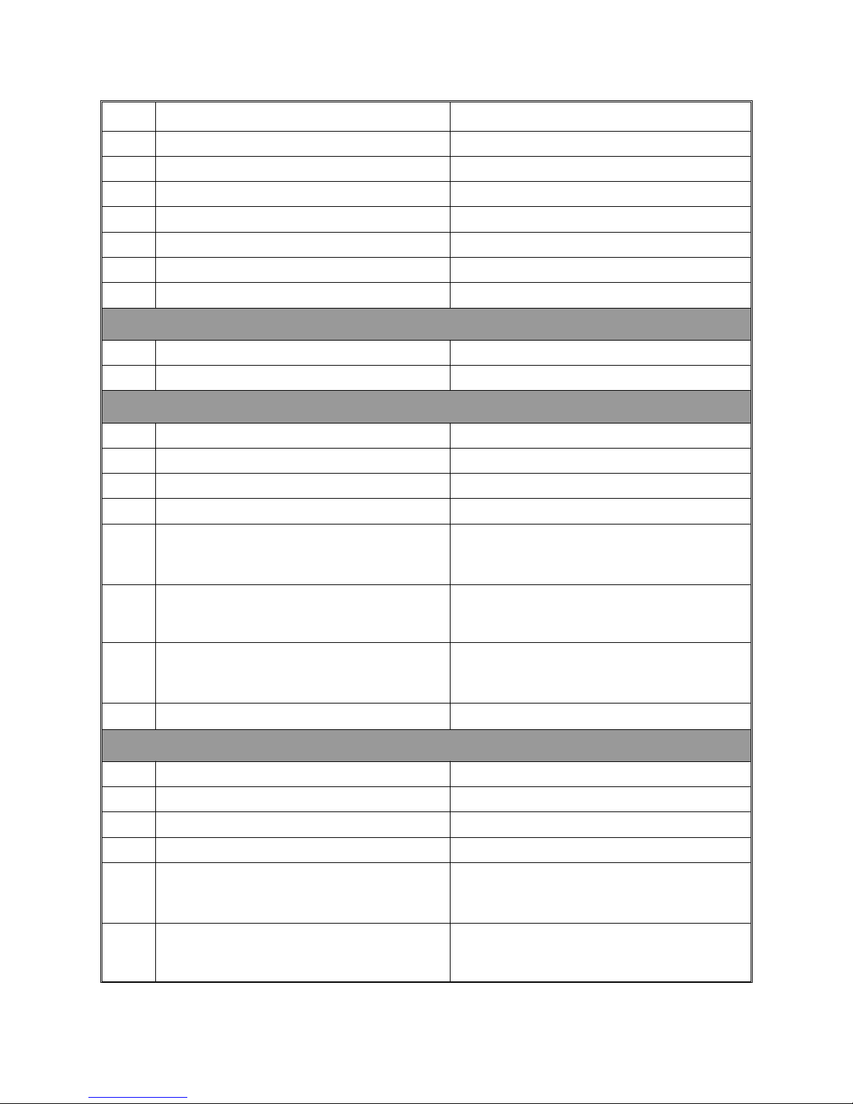
No. Parameter Notes
31 Current Program Number Read only
32 Current Segment Number Read only in current running/held program
33 Segment Time Remaining Read only
34 Profiler Commands Write only - see Subsection 5.6.
35 Power Fail Recovery 0 = Cold start, 1 = Warm start
36 Guaranteed Soak Type 0 = disabled, 1 = enabled, 2 = manual
37 Cycles Remaining Read only
Instrument ID Parameters
121 Manufacturer ID Read only - 231
122 Equipment ID Read only - 6400
Segment Parameters - Program 1
1100Run Program (value = Delayed Start value) Write only
1101 No. of Cycles Programmed 1 to 9999 plus 10000 (INF)
1102 Timebase 0 = hours/minutes, 1 = minutes/seconds
1103 Guaranteed Soak Band value 0 (OFF), 1 to span
1104
1119
1120
1135
1136
1151
1152 Event Marker settings
Final Setpoint values
to
(Soak = -32768, End = -16384)
Rate values (Soak = -32768, End = -16384) Segment 1 at address 1120
to
Time values Segment 1 at address 1136
to
Segment 1 at address 1104
⇓
Segment 16 at address 1119
⇓
Segment 16 at address 1135
⇓
Segment 16 at address 1151
Bit 0 = Event 16 ⇒ Bit 15 = Event 1
Segment Parameters - Program 2
1200Run Program (value = Delayed Start value) Write only
1201 No. of Cycles Programmed 1 to 9999 plus 10000 (INF)
1202 Timebase 0 = hours/minutes, 1 = minutes/seconds
1203 Guaranteed Soak Band value 0 (OFF), 1 to span
1204
1219
1220
1235
Final Setpoint values
to
(Soak = -32768, End = -16384)
Rate values (Soak = -32768, End = -16384) Segment 1 at address 1220
to
Segment 1 at address 1204
⇓
Segment 16 at address 1219
⇓
Segment 16 at address 1235
5-9
Page 48
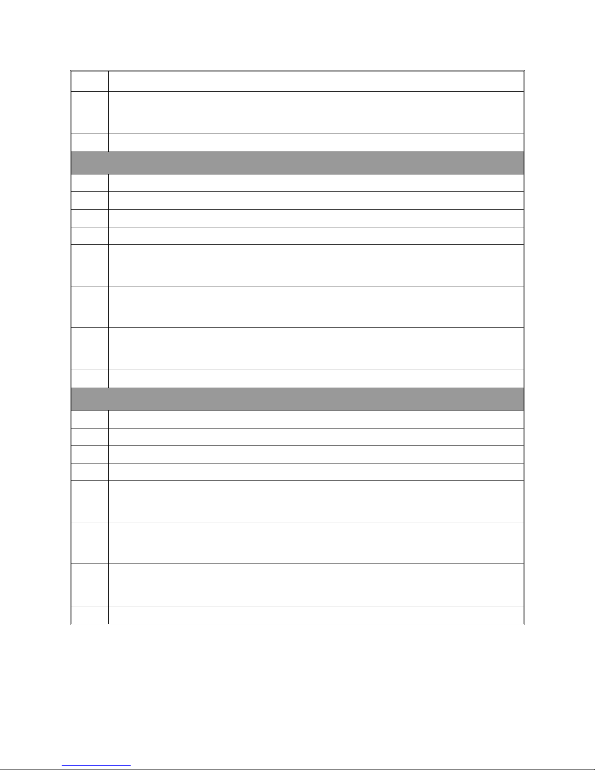
No. Parameter Notes
1236
1251
1252 Event Marker settings
Time values Segment 1 at address 1236
to
⇓
Segment 16 at address 1251
Bit 0 = Event 16 ⇒ Bit 15 = Event 1
Segment Parameters - Program 3
1300 Run Program (value = Delayed Start value) Write only
1301 No. of Cycles Programmed 1 to 9999 plus 10000 (INF)
1302 Timebase 0 = hours/mnutes, 1 = minutes/seconds
1303 Guaranteed Soak Band value 0 (OFF), 1 to span
1304
1319
1320
1335
1336
1351
1352 Event Marker settings
Final Setpoint values
to
(Soak = -32768, End = -16384)
Rate values (Soak = -32768, End = -16384) Segment 1 at address 1320
to
Time values Segment 1 at address 1336
to
Segment 1 at address 1304
⇓
Segment 16 at address 1319
⇓
Segment 16 at address 1335
⇓
Segment 16 at address 1351
Bit 0 = Event 16 ⇒ Bit 15 = Event 1
Segment Parameters - Program 4
1400 Run Program (value = Delayed Start value) Write only
1401 No. of Cycles Programmed 1 to 9999 plus 10000 (INF)
1402 Timebase 0 = hours/minutes, 1 = minutes/seconds
1403 Guaranteed Soak Band value 0 (OFF), 1 to span
1404
1419
1420
1435
1436
1451
1452 Event Marker settings
Some of the parameters which do not apply to a particular instrument configuration
(e.g. PB2 on a single output instrument) will accept reads & writes. Others will accept
reads only, and will return an exception if an attempt is made to write values to them.
Final Setpoint values
to
(Soak = -32768, End = -16384)
Rate values (Soak = -32768, End = -16384) Segment 1 at address 1420
to
Time values Segment 1 at address 1436
to
Segment 1 at address 1404
⇓
Segment 16 at address 1419
⇓
Segment 16 at address 1435
⇓
Segment 16 at address 1451
Bit 0 = Event 16 ⇒ Bit 15 = Event 1
5 -10
Page 49
The values read will in all cases be undefined. It is the user’s responsibility to make
sure that values read reflect a possible state of the instrument.
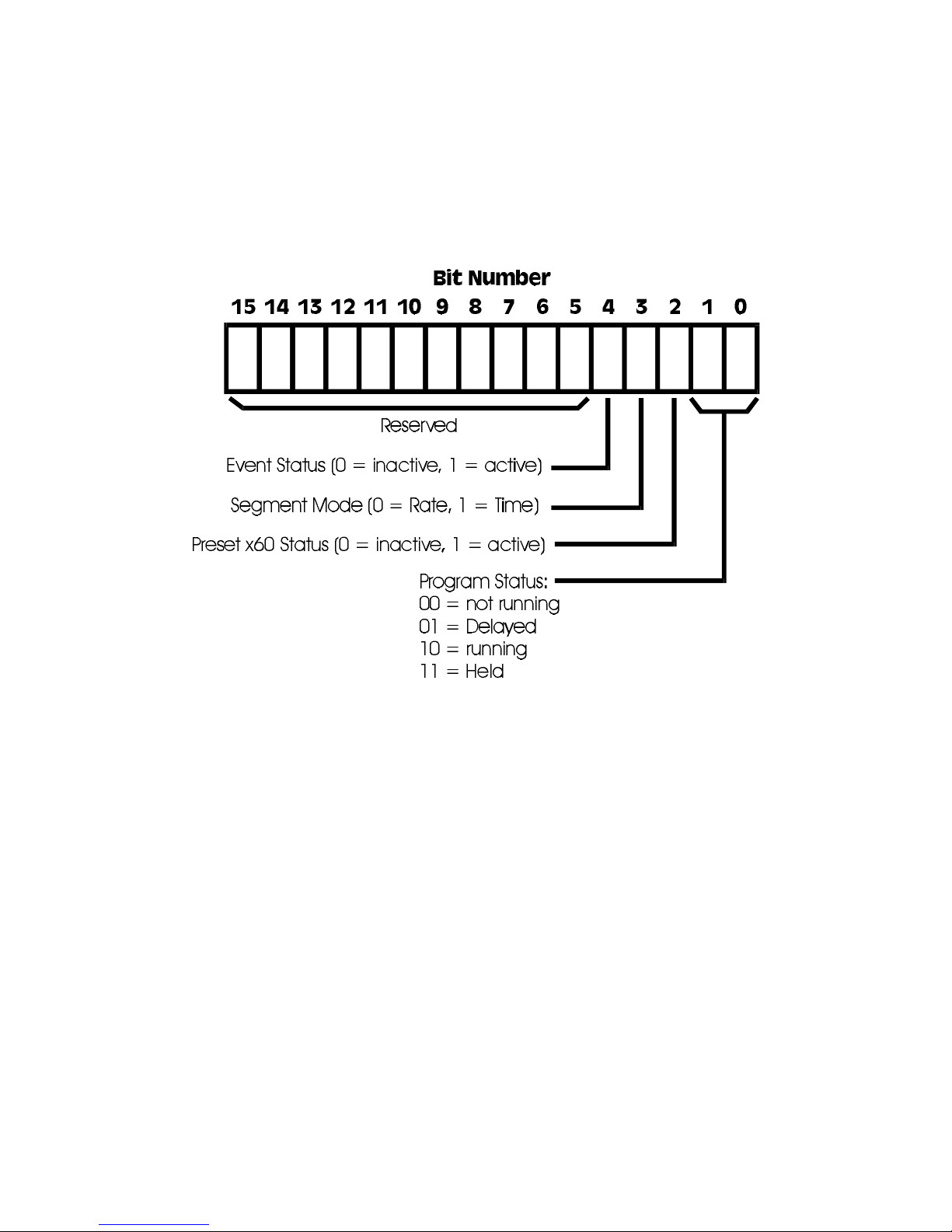
5.5 PROFILER STATUS BYTE
The Profiler Status byte has the following format:
5.6 PROFILER COMMANDS
The Profiler Commands are as follows:
0001 Manually hold currently-running program
0002 Release Manual Hold on current program
0003 Abort currently-running/held program
5-11
Page 50
6 CONFIGURATION MODE
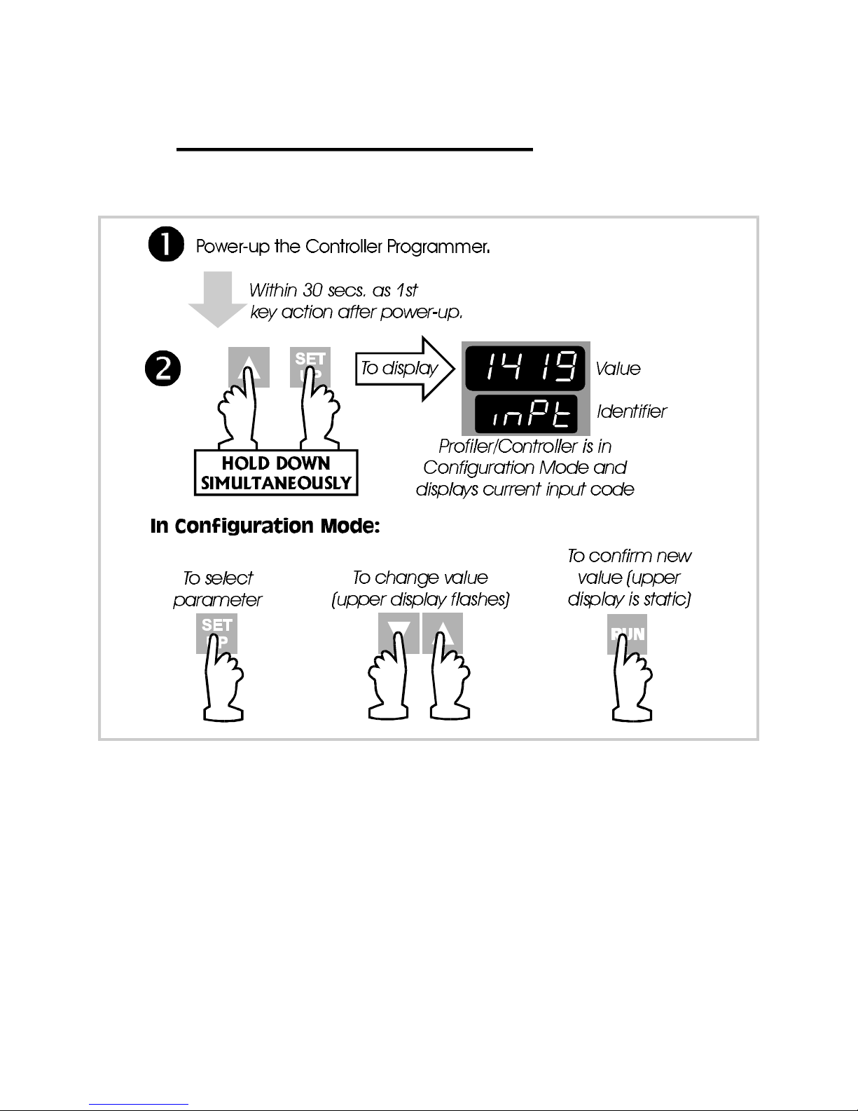
6.1 ENTRY INTO CONFIGURATION MODE
Figure 6 -1 Entry into Configuration Mode
NOTE: Changes to the value/setting of certain Configuration Mode
parameters (e.g. input range, output use and type) will cause the Set
Up Mode parameters to be automatically set to their default values the
next time Set Up Mode is entered (see also beginning of Section 4).
6.2 H ARDWARE DEFINITION CODE
This parameter is a special facility in Configuration Mode, which is used to represent
the hardware fitted (input type, Output 1 type, Output 2 type and Output 3 type); this
must be compatible with the hardware actually fitted. For access to, and adjustment
of, the Hardware Definition Code, see Figure 6-2 and Table 6 -1 .
6 -1
Page 51
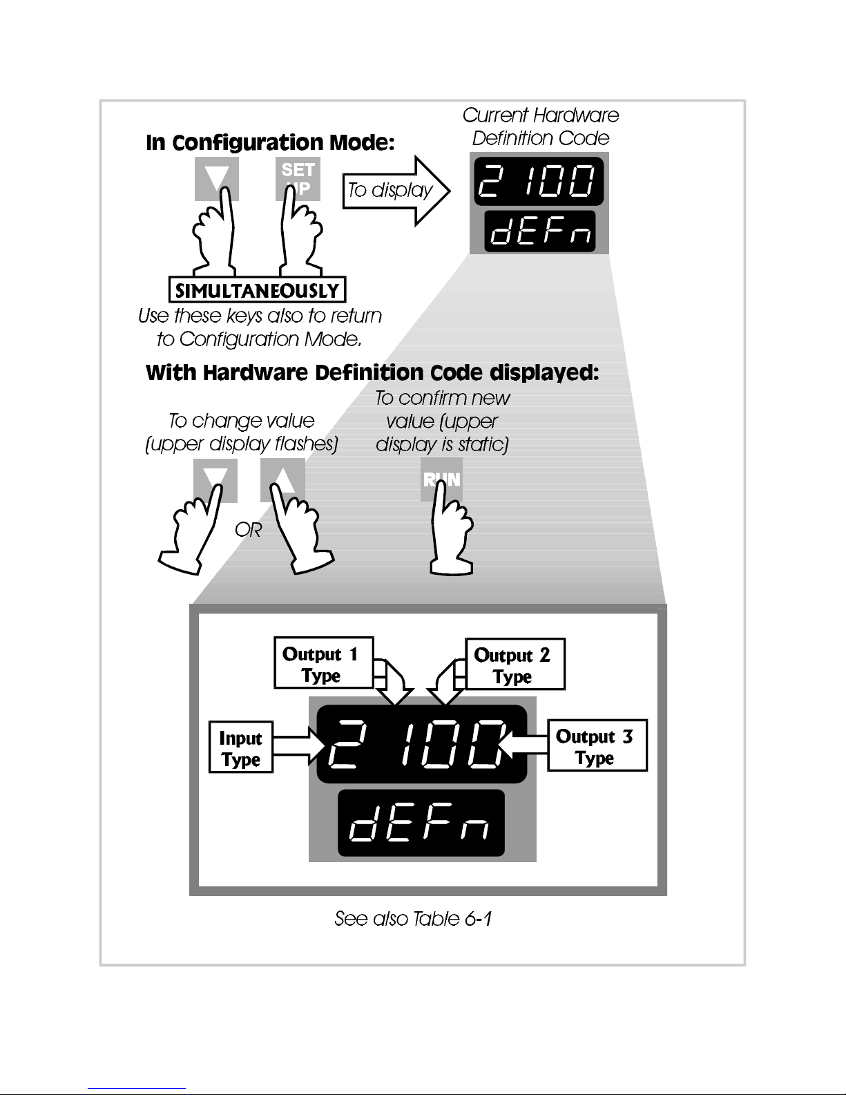
Figure 6-2 Hardware Definition Code - Access and Adjustment
6-2
Page 52
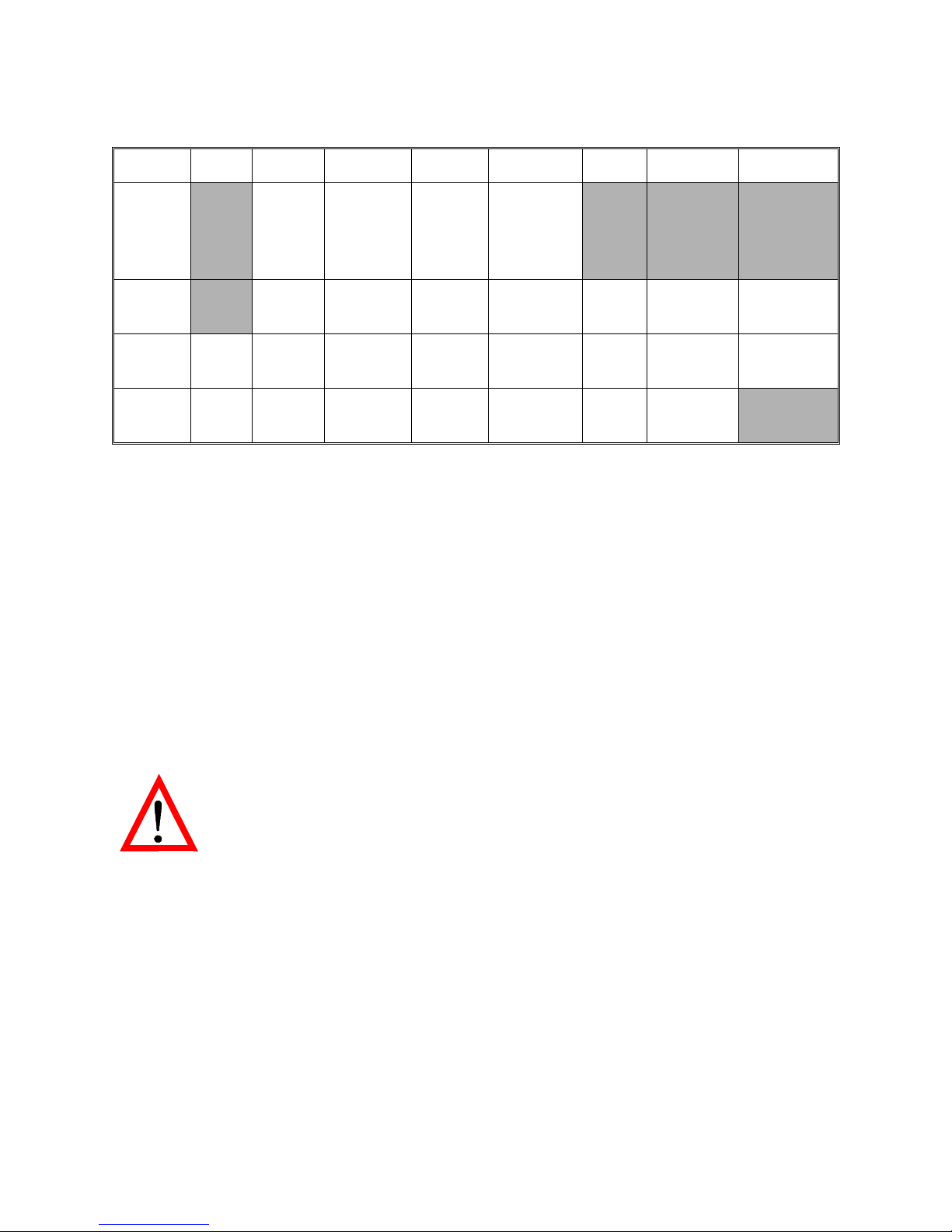
Table 6 -1 Hardware Definition Code - Input/Output Type Selection
Value 0 1 2 3 4 5 7 8
Input RTD/
Linear
Thermocouple
Linear
DC mA
Linear
DC V
DC
mV
Output
1
Output 2Not
fitted
Output 3Not
fitted
Relay SSR
Drive
Relay SSR
Drive
Relay SSR
Drive
DC
0 - 10VDC0 - 20mADC0 - 5VDC4 - 20mA
DC
0 - 10VDC0 - 20mADC0 - 5VDC4 - 20mA
DC
0 - 10VDC0 - 20mADC0 - 5VDC4 - 20mA
Solid
State
Solid
State
NOTES:
1. If Output 2 is a relay/Solid State/SSR Drive output, it may be a control output
(COOL), an event output or an alarm output; if it is set to be a DC output, it
can only be a control output (COOL).
2. If Output 3 is a relay/SSR Drive output (it cannot be an Solid State output), it
can only be an event output or an alarm output; if it is set to be a DC output, it
can only be a recorder (i.e. re-transmitted process variable or setpoint) output.
The maximum setting available for this code is 4887. For example, the code for a
thermocouple input, DC 4 - 20mA primary output (Output 1) and relay Output 3
would be 2701.
NOTE: It is essential that this code is changed promptly whenever
there is a change to the instrument’s hardware configuration
(change of input/output type, alarm/recorder output
added/removed etc.). The instrument software depends upon this
code to ensure that the instrument operates correctly.
This code may be viewed as a Read Only display in Base Mode (see Subsection
1.11 ).
6.3 OPTION SELECTION
This indicates the option fitted (Communications Option, Remote Run/Hold option or
no option at all). It is accessed whilst the Hardware Definition Code is displayed (see
Figure 6-3).
6 -3
Page 53
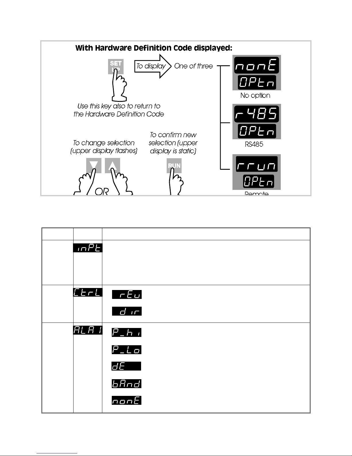
Figure 6-3 Option Selection
6.4 CONFIGURATION MODE PARAMETERS
Parameter Identifier Description
Input
Range
Output
1
Action
Alarm 1
Type
A four-digit code (see Appendix B). Default settings:
Thermocouple - 1419 (Type J, 0 - 761 °C)
RTD/Linear mV - 7220 (RTD Pt100 0 - 800°C)
Linear mA - 3414 (4 - 20mA)
Linear V - 4446 (0 - 10V)
Reverse-acting
Direct-acting
Process High Alarm
Process Low Alarm
Deviation Alarm
Band Alarm
No alarm
6-4
Page 54
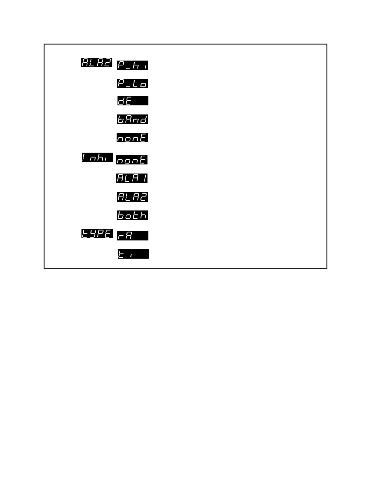
Parameter Identifier Description
Alarm 2
Type
Alarm
Inhibit
Program
Mode
Process High Alarm
Process Low Alarm (default)
Deviation Alarm
Band Alarm
No alarm
No alarms inhibited
Alarm 1 inhibited
Alarm 2 inhibited
Both Alarm 1 & Alarm 2 inhibited
Rate
Time
6-5
Page 55
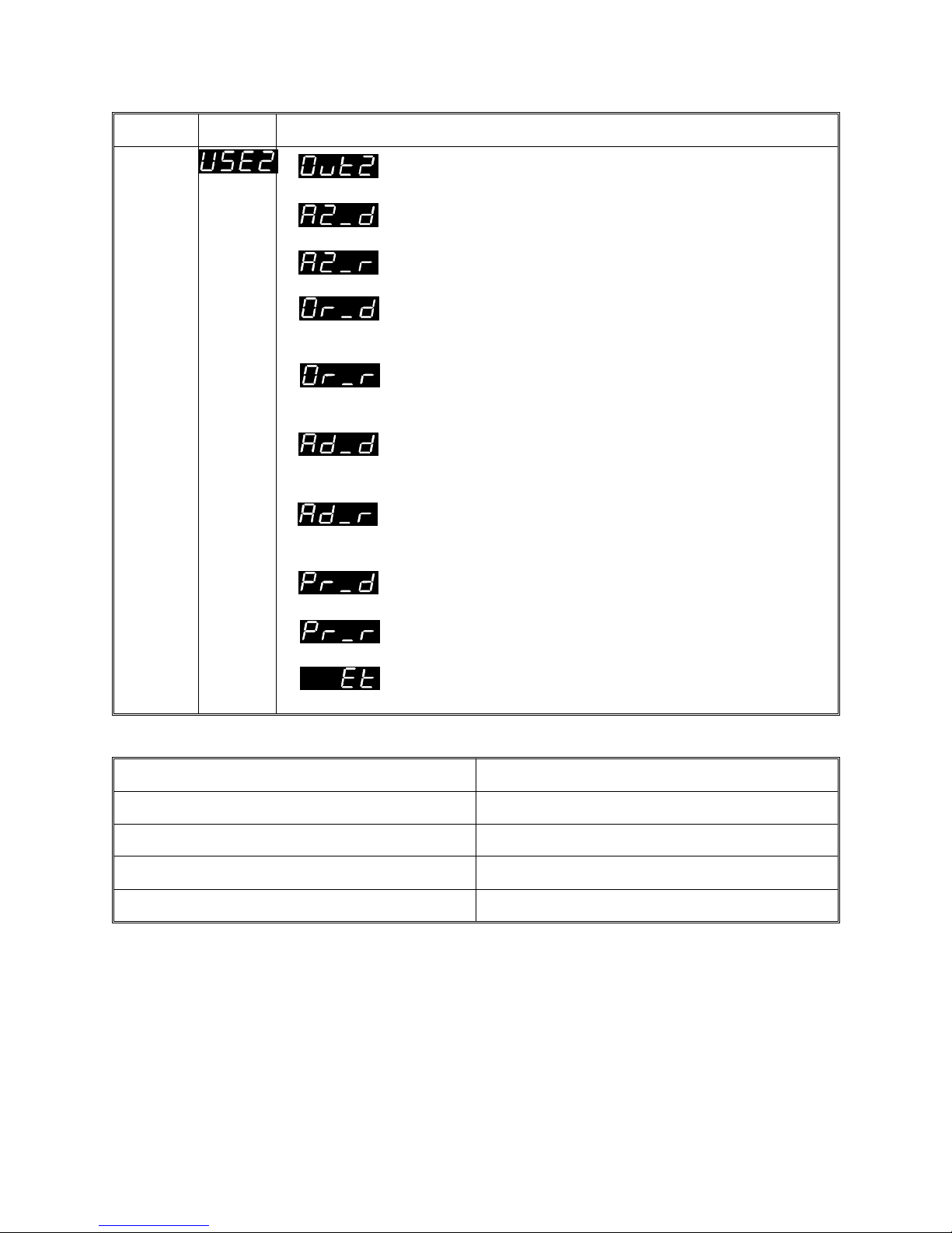
Parameter Identifier Description
Output
2
Usage
Output 2 secondary control (COOL) output
Alarm 2 hardware output, direct-acting. Available only if relay/DC Pulse/AC SSR output.
Alarm 2 hardware output, reverse-acting. Available only if relay, DC Pulse or AC SSR output.
Direct-acting output for Logical OR of Alarm 1
and Alarm 2. Available only if relay, DC Pulse,
or AC SSR output.
Reverse-acting output for Logical OR of Alarm 1
and Alarm 2. Available only if relay, DC Pulse,
or AC SSR output.
Direct-acting output for Logical AND of Alarm 1
and Alarm 2. Available only if relay, DC Pulse,
or AC SSR output.
Reverse-acting output for Logical AND of Alarm
1 and Alarm 2. Available only if relay, DC Pulse,
or AC SSR output.
Profile Active output, direct-acting. Available
only if relay, DC Pulse or AC SSR output.
Profile Active output, reverse-acting. Available
only if relay, DC Pulse or AC SSR output.
Event output, direct-acting. Available only if
relay, DC Pulse or AC SSR output.
Example of Logical Combination of Alarms - Logical OR of Alarm 1 & Alarm 2
Direct-acting Reverse-acting
AL1 OFF, AL2 OFF: Relay de-energised AL1 OFF, AL2 OFF: Relay energised
AL1 ON, AL2 OFF: Relay energised AL1 ON, AL2 OFF: Relay de-energised
AL1 OFF, AL2 ON: Relay energised AL1 OFF, AL2 ON: Relay de-energised
AL1 ON, AL2 ON: Relay energised AL1 ON, AL2 ON: Relay de-energised
6-6
Page 56
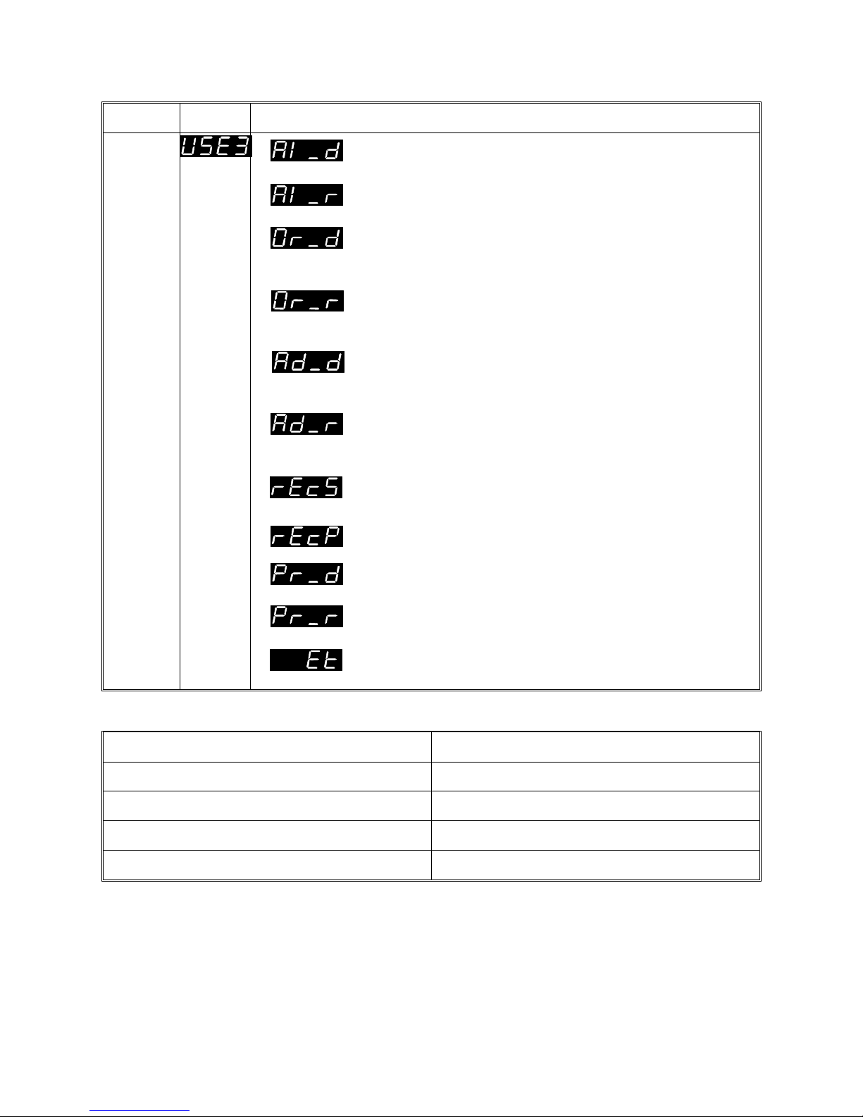
Parameter Identifier Description
Output
3
Usage
Alarm 1 hardware output, direct-acting. Available only if relay/DC Pulse/AC SSR output.
Alarm 1 hardware output, reverse-acting. Available only if relay, DC Pulse or AC SSR output.
Direct-acting output for Logical OR of Alarm 1
and Alarm 2. Available only if relay, DC Pulse,
or AC SSR output.
Reverse-acting output for Logical OR of Alarm 1
and Alarm 2. Available only if relay, DC Pulse,
or AC SSR output.
Direct-acting output for Logical AND of Alarm 1
and Alarm 2. Available only if relay, DC Pulse,
or AC SSR output.
Reverse-acting output for Logical AND of Alarm
1 and Alarm 2. Available only if relay, DC Pulse,
or AC SSR output.
Recorder Output - Setpoint (DC output only)
Recorder Output - Process Variable
(DC Output only)
Profile Active output, direct-acting. Available
only if relay or DC Pulse output.
Profile Active output, reverse-acting. Available
only if relay or DC Pulse output.
Event output, direct-acting. Available only if
relay or DC Pulse output.
Example of Logical Combination of Alarms - Logical AND of Alarm 1 & Alarm 2
Direct-acting Reverse-acting
AL1 OFF, AL2 OFF: Relay de-energised AL1 OFF, AL2 OFF: Relay energised
AL1 ON, AL2 OFF: Relay de-energised AL1 ON, AL2 OFF: Relay energised
AL1 OFF, AL2 ON: Relay de-energised AL1 OFF, AL2 ON: Relay energised
AL1 ON, AL2 ON: Relay energised AL1 ON, AL2 ON: Relay de-energised
6-7
Page 57
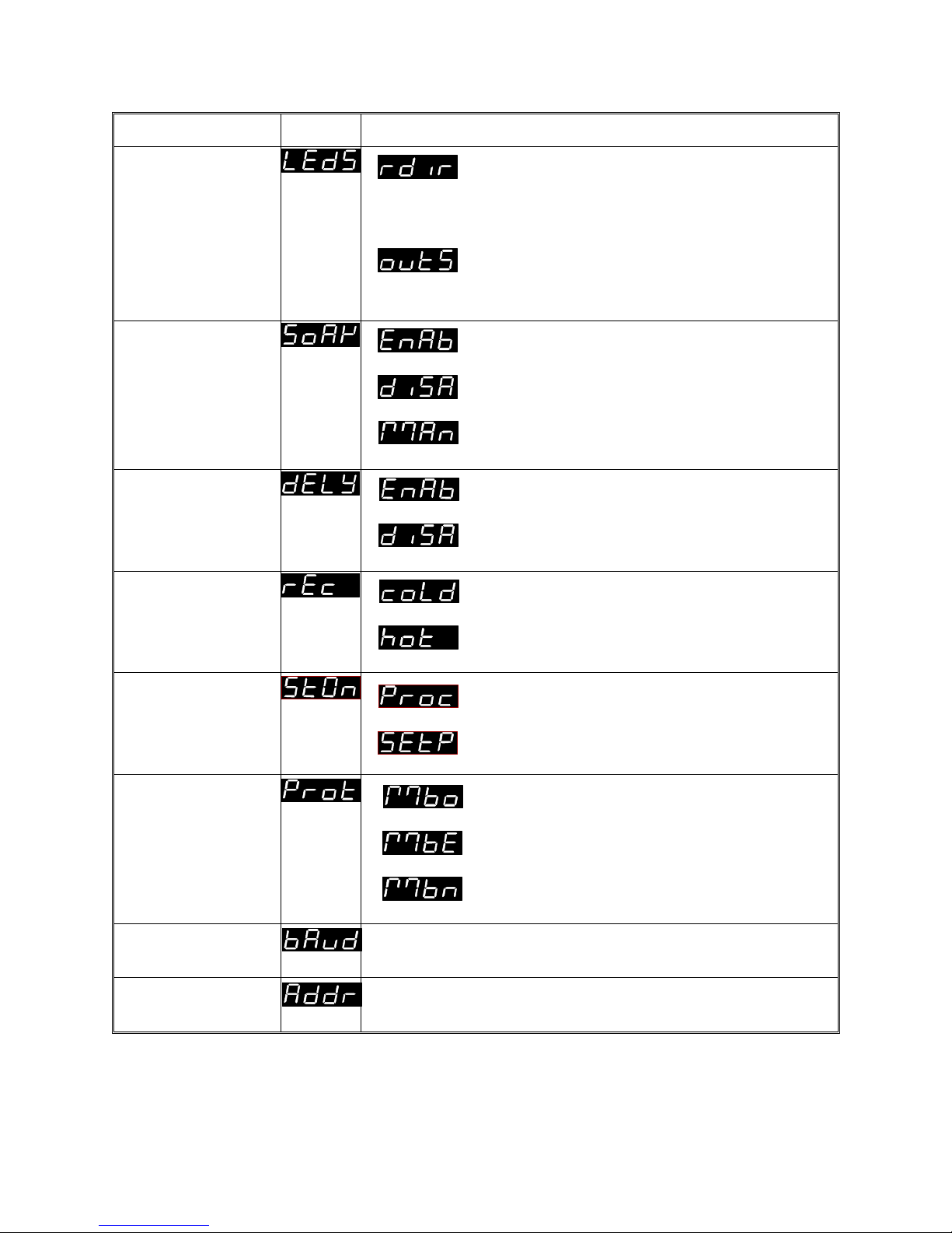
Parameter Identifier Description
∆ & ∇ LEDs Usage
(on Front Panel)
Guaranteed
Soak
Enable/Disable
(see Subsection
3.2.5)
Delayed Start
Enable/Disable
Power Loss
Recovery
Ramp direction:
∆ = positive ramp
∇ = negative ramp
both = dwell
Output state:
∆ = Output 1 ON
∇ = Output 2 ON
Enabled
Disabled
Manual
Enabled
Disabled
Cold Start (program re-started from
beginning)
Warm Start (program resumed from
point at which power failed)
Start On Start program with setpoint at
current process variable value
Start program with setpoint at
Controller Setpoint value
Communications
MODBUS with odd parity
Protocol
MODBUS with even parity
MODBUS with no parity
Communications
Selectable: 1200, 2400, 4800, 9600 Baud
Baud Rate
Communications
Address
Unique address assigned to the controller;
in the range 1 - 255.
Continued overleaf⇒⇒⇒⇒⇒⇒
6-8
Page 58
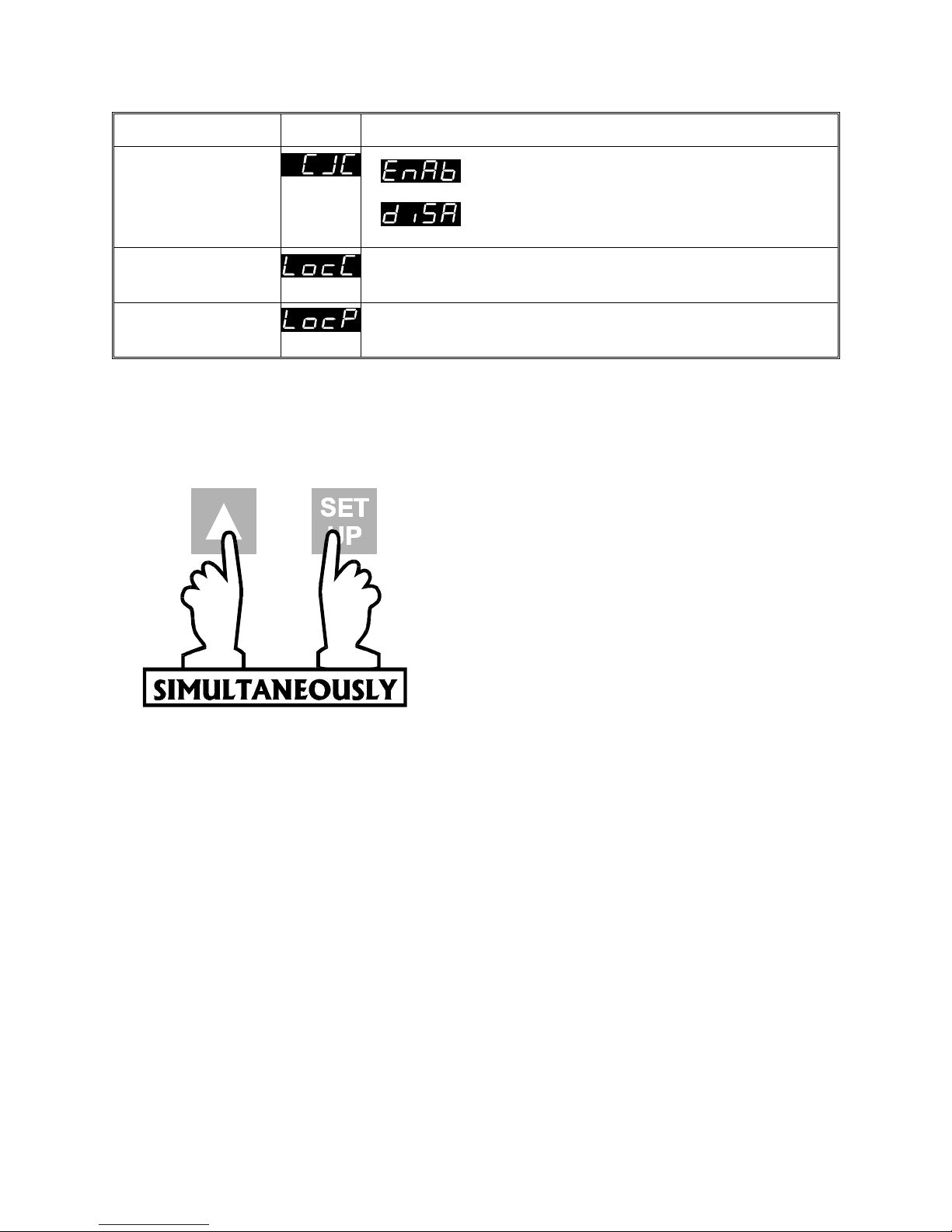
Parameter Identifier Description
Cold Junction
Enabled (default)
Compensation
Enable/Disable*
Controller Set-Up
Mode Lock Code
Program Define
Mode Lock Code
* Appears only if a thermocouple input is selected (see Hardware definition Code).
Read Only display of current four-digit Set Up Mode
Lock Code.
Read Only display of current four-digit Program
Define Mode Lock Code.
Disabled
6.5 EXIT FROM CONFIGURATION MODE
NOTE: An automatic exit to Operator
Mode will be made if, in Configuration
Mode, there is no front panel key activity
for two minutes.
The exit is made via the power-up self-test
routines which include a lamp test.
6 -9
Page 59
7 INTERNAL LINKS AND SWITCHES
7.1 REMOVING THE CONTROLLER PROGRAMMER FROM ITS
HOUSING
WARNING ! Before removing the instrument from its housing, ensure that
all power has been removed from the rear terminals. Disregard for
these instructions may cause injury or death!
To withdraw the instrument from its housing, simply grip the side edges of the front
panel (there is a finger grip on each edge) and pull the instrument forwards. This will
release the instrument from its rear connectors in the housing and will give access to
the instrument PCBs. Take note of the orientation of the instrument for subsequent
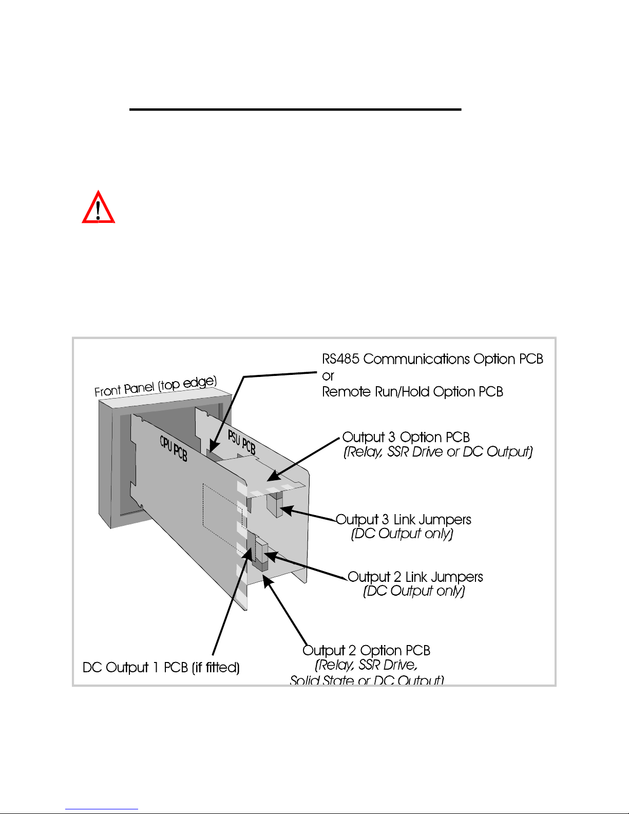
replacement into the housing.The positions of the PCBs in the instrument are shown in
Figure 7 -1.
Figure 7 -1 PCB Positions
7-1
Page 60
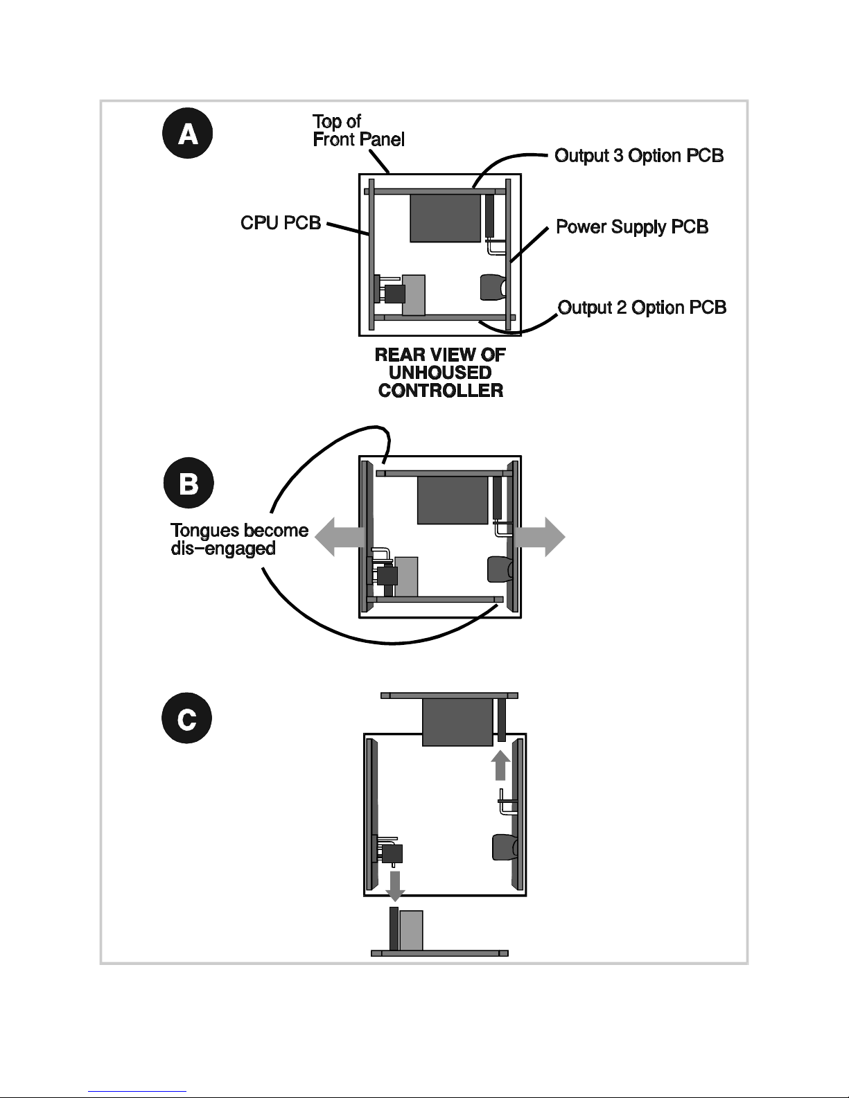
Figure 7 -2 Removing the Output 2/Output 3 Option PCBs
7-2
Page 61

7.2 REMOVING/ REPLACING THE OUTPUT 2/OUTPUT 3
OPTION PCBs
With the instrument removed from its housing:
1. Gently push the rear ends of the CPU PCB and Power Supply PCB apart
slightly, until the two tongues on each of the Output 2/Output 3 Option PCBs
become dis-engaged - see Figure 7-2B; The Output 2 Option PCB tongues
engage in holes in the Power Supply PCB and the Output 3 Option PCB
tongues engage in holes on the CPU PCB.
2. Carefully pull the required Option PCB (Output 2 or Output 3) from its
connector (Output 2 Option PCB is connected to the CPU PCB and Output 3
Option PCB is connected to the Power Supply PCB) - see Figure 7-2C. Note the
orientation of the PCB in preparation for its replacement.
Adjustments may now be made to the link jumpers on the CPU PCB, the Output
2/Output 3 Option PCBs (if DC output) and (if fitted) the DC Output 1 PCB. The
replacement procedure is a simple reversal of the removal procedure.
7.3 REMOVING/REPLACING THE RS485 COMMUNICATIONS
OPTION PCB OR REMOTE RUN/HOLD OPTION PCB
The RS485 Communications Option PCB or Remote Run/Hold Option PCB is mounted
on the inner surface of the Power Supply PCB and can be removed when the
instrument is removed from its housing (see Subsection 7.1 ) Figure 7 -3 illustrates the
removal/replacement procedure. It is not necessary to remove the Output 2/Output
3 Option PCBs to perform this procedure.
7.4 REPLACING THE INSTRUMENT IN ITS HOUSING
To replace the instrument, simply align the CPU PCB and Power Supply PCB with their
guides and connectors in the housing and slowly but firmly push the instrument into
position.
CAUTION: Ensure that the instrument is correctly orientated. A stop
will operate if an attempt is made to insert the instrument in the
wrong orientation (e.g. upside-down). This stop must not be
over-ridden.
7-3
Page 62
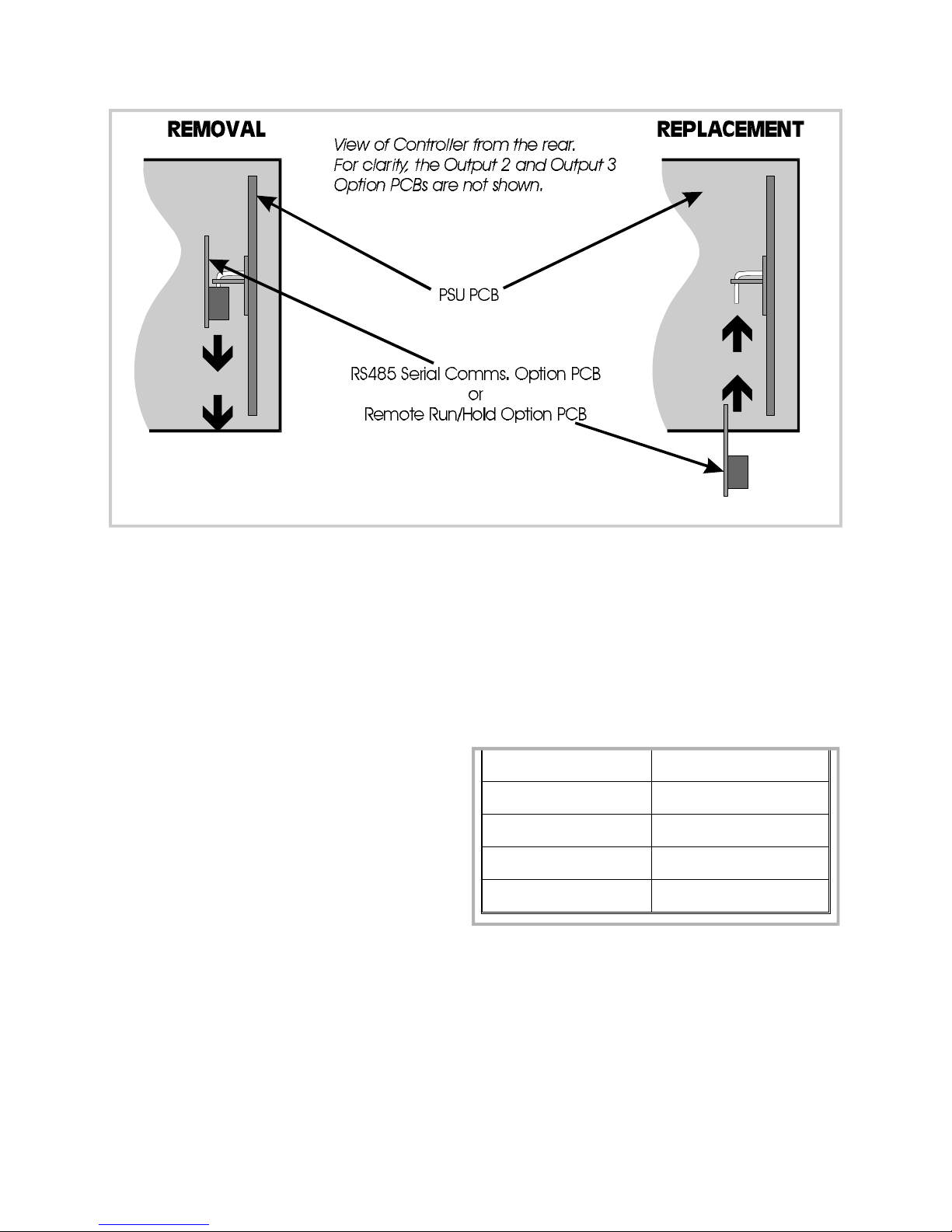
Figure 7 -3 Removing the RS485 Communications Option PCB
or the Remote Run/Hold Option PCB
7.5 SELECTION OF INPUT TYPE AND OUTPUT 1 TYPE
The selection of input type and Output 1 type is accomplished on link jumpers on the
CPU PCB. The CPU PCB may be either of two forms: (a) for a relay, solid state or SSR
drive Output 1 (see Figure 7-4) or for a DC Output 1 (see Figure 7 -5 ).
7.5.1 Input Type
The required input type is selected on
link jumpers LJ1/LJ2/LJ3 on the CPU PCB
(see Figure 7 -4 or 7 -5 , as appropriate,
and Table 7-1).
7 -4
Table 7 -1 Selection of Input Type
Input Type Link Jumpers Fitted
RTD or DC (mV) None (Parked)
Thermocouple LJ3
DC (mA) LJ2
DC (V) LJ1
Page 63
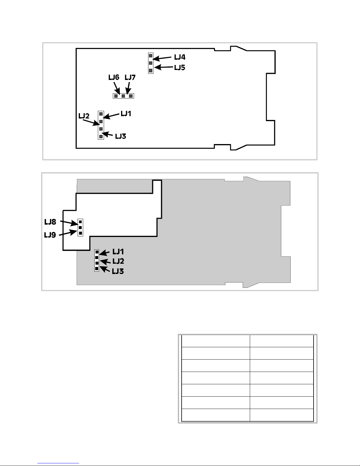
Figure 7-4 CPU PCB (Relay/SSR Drive/Solid State Output 1)
Figure 7 -5 CPU PCB (DC Output 1)
7.5.2 Primary Output (Output 1) Type
The required type of Output 1 is
selected by Link Jumpers LJ4, LJ5, LJ6
and LJ7 on the Relay/SSR Drive/Solid
State Output 1 CPU PCB (see Figure 7-4
and Table 7-2) or, on the DC Output 1
CPU PCB, Link Jumpers LJ8 and LJ9 (see
Figure 7-5 and Table 7 -2 ).
Table 7 -2 Selection of Output 1 Type
Output 1 Type Link Jumpers Fitted
Relay or Solid State LJ5 & LJ6
SSR Drive LJ4 & LJ7
DC (0 - 10V) LJ8
DC (0 - 20mA) LJ9
DC (0 - 5V) LJ8
DC (4 - 20mA) LJ9
7 -5
Page 64
7.6 OUTPUT 2 TYPE/ OUTPUT 3 TYPE
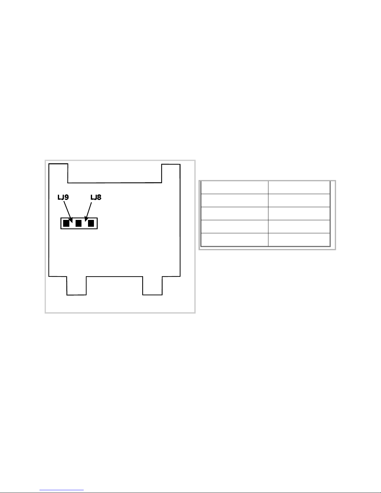
The type of output for Output 2 and Output 3 is determined by the Option PCB fitted
in the appropriate position (see Figure 7 - 1 ) and, in the case of the DC Output Option
PCB being fitted, the setting of Link Jumpers LJ8 and LJ9 on that Option PCB (see
Figure 7-6 and Table 7 -3 ). There are four types of option PCB which may be used for
Output 2 and Output 3:
1. Relay Output Option PCB (no link jumpers)
2. SSR Drive Output Option PCB (no link jumpers)
3. Solid State Output Option PCB (no link jumpers) - Output 2 only
4. Analog DC Output Option PCB (link jumpers as shown in Figure 7-6)
Table 7 -3 Selection of Output 2 &
Output 3 Type (DC)
DC Output Range Link Jumpers Fitted
DC (0 - 10V) LJ8
DC (0 - 20mA) LJ9
DC (0 - 5V) LJ8
Figure 7-6 DC Output Option PCB
(Output 2/Output 3)
DC (4 - 20mA) LJ9
7-6
Page 65

APPENDIX A PRODUCT CODES
INSTRUCTIONS
Select the desired key number. The arrow to the right marks the selections available.
Make one selection from each of Tables I through V using the column below the
appropriate arrow. An asterisk denotes unrestricted availability. A letter denotes
restricted availability.
Field Meaning Description Selection Availability
Key
Number
DCP50
Controller
Programmer
1
-DIN Controller Programmer DCP50
16
⇓
Table I Output 1
(Control 1)
Relay
SSR Drive
Linear (4 - 20mA factory-set)
Solid State
Table II Output 2
(Control 2 or
Alarm 2)
Not fitted
Relay
SSR Drive
Solid State
Output 2
Linear (4 - 20mA factory-set) 7 *
(Control 2 only
Table III Output 3 (Alarm
1 only)
Not fitted
Relay
SSR Drive
Output 3
Linear (4 - 20mA factory-set) 7 *
(Retransmission output
only)
Table IV Option 1 No option fitted
Remote Run/Hold (Digital) Input
RS485 MODBUS Communications
1
2
7
8
0
1
2
8
0
1
2
0
2
3
*
*
*
*
*
*
*
*
*
*
*
*
*
*
Table V Option 2 90 - 264V AC Power Supply
24 - 48V DC Power Supply
1
2
*
*
A-1
Page 66
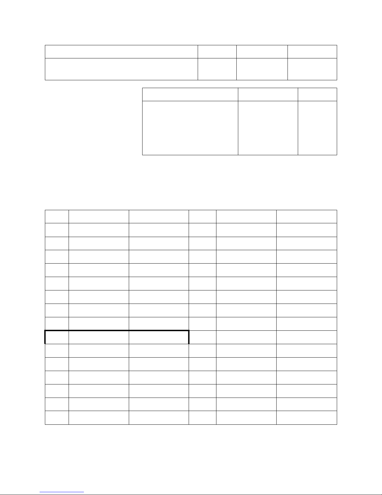
Additional Literature Description Ref. Availability
Product Manual for Digital Controller
English 57-77-25-17 *
Programmer
Upgrade Kits Ref. Availability
Relay Output PWA
SSR Output PWA
Linear Output PWA
RS485 Comms. PWA I
Remote Run/Hold PWA I
46189010-501
46189011-501
46189012-501
46189013-501
46189014-501
*
*
*
*
*
I Mutually exclusive
INPUT TYPE (User selectable) Input ranges available (selectable from front panel):
Thermocouple Inputs:
Type Input Range Dislayed Code Type Input Range Displayed Code
R
R
0 - 1650 °C
32 - 3002 °F
1127 J
1128 T
32 - 1401 °F
-200 - 262 °C
1420
1525
S
S
J
J
J
J
J
L
L
L
L
L
L
0 - 1649°C
32 - 3000°F
0.0 - 205.4°C
32.0 - 401.7 °F
0 - 450 °C
32 - 842°F
0 - 761 °C
0.0 - 205.7 °C
32.0 - 402.2 °F
0 - 450°C
32 - 841°F
0 - 762°C
32 - 1403°F
1227 T
1228 T
1415 T
1416 K
1417 K
1418 K
1419 * K
1815 B
1816 B
1817 N
1818 N
1819 C/W5
1820 C/W5
-328 - 503 °F
0.0 - 260.6°C
32.0 - 501.0 °F
-200 - 760°C
-328 - 1399 °F
-200 - 1373 °C
-328 - 2503 °F
211 - 3315 °F
100 - 1824°C
0 - 1399°C
32 - 2550°F
0 - 2316°C
32 - 4201°F
1526
1541
1542
6726
6727
6709 *
6710
1934
1938
5371
5324
1541
1542
A-2
* Default
Page 67
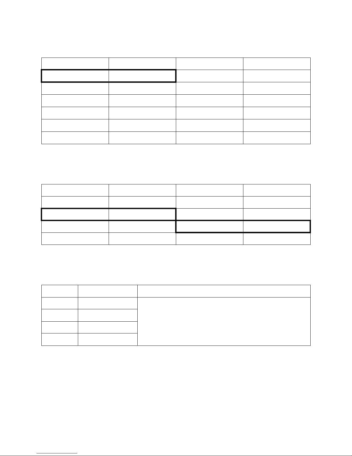
RTD Inputs:
Input Range Displayed Code Input Range Displayed Code
0 - 800 °C *
32 - 1471°F
32 - 571°F
-100.9 - 100.0 °C
-149.7 - 211.9 °F
0 - 300 °C
7220
7221
2229
2230
2231
2251
0.0 - 100.9°C
32.0 - 213.6 °F
-200 - 206°C
-328 - 402°F
-100.9 - 537.3 °C
-149.7 - 999.1 °F
* default
DC Inputs:
Input Range Displayed Code Input Range Displayed Code
0 - 20mA 3413 0 - 5V 4445
4 - 20mA * 3414 1 - 5V 4434
0 - 50mV 4443 0 - 10V * 4446
10 - 50mV 4499 2 - 10V 4450
2295
2296
2297
2298
7222
7223
* Default
OUTPUT 1 TYPE (CONTROL 1)
Code Description Notes
1 Relay Linear type factory-set to 4 - 20mA.
2 SSR Drive
7 Solid State
8 Linear (4 - 20mA)
A -3
Page 68
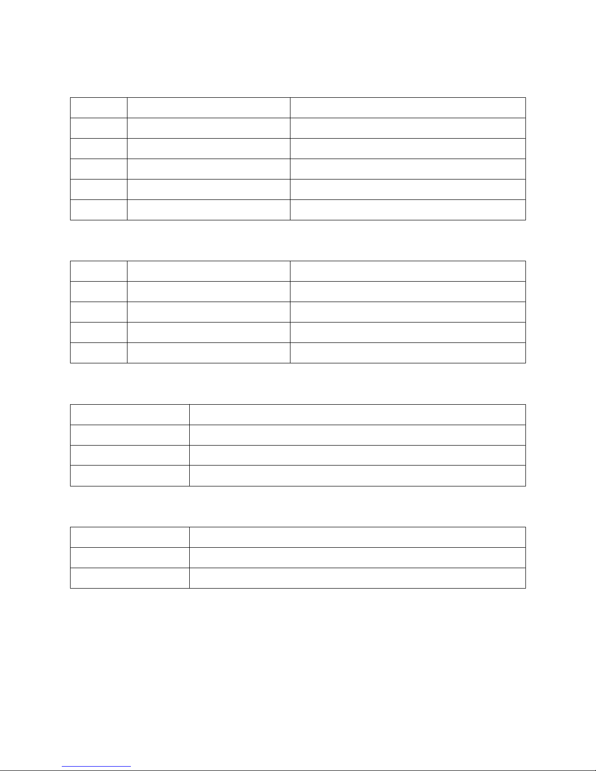
OUTPUT 2 TYPE (CONTROL 2 OR ALARM 2)
Code Description Notes
0 Not fitted
1 Relay Control 2 or Alarm 2
2 SSR Drive Control 2 or Alarm 2
7 Linear (4 - 20mA factory-set) Control 2 only
8 Solid state Control 2 or Alarm 2
OUTPUT 3 TYPE (ALARM 1 OR RE-TRANSMITTED OUTPUT)
Code Description Notes
0 Not fitted
1 Relay Alarm 1 only
2 SSR Drive Alarm 1 only
7 Linear (4 - 20mA factory-set) Re-transmission output only
OPTION 1
Code Description
OPTION 2
Code Description
0 No option fitted
2 Remote Run/Hold (Digital) Input
3 RS485 MODBUS Communications
1 90 - 264V AC Power Supply
2 24 -m 48V DC Power Supply
A-4
Page 69
APPENDIX B PRODUCT SPECIFICATION
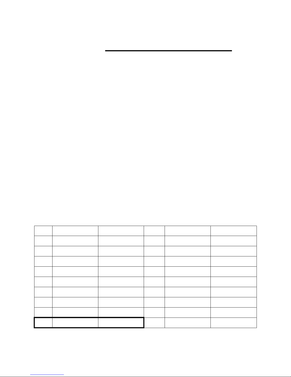
UNIVERSAL INPUT
General
Maximum per Controller: One
Input Sample Rate: Four samples/second
Digital Input Filter: Time constant selectable from front panel -
0.0 (i.e. OFF), 0.5 to 100.0 seconds in
0.5-second increments.
Input Resolution: 14 bits approximately; always four times better
than display resolution.
Input Impedance: Greater than 100M Ω resistive (except for DC
mA and V inputs).
Isolation: Universal input isolated from all outputs except
SSR at 240V AC.
Process Variable Offset:
Adjustable ±input span.
Thermocouple: Ranges selectable from front panel:
Type Input Range Dislayed Code Type Input Range Displayed Code
R
R
S
S
J
J
J
J
J
0 - 1650 °C
32 - 3002 °F
0 - 1649°C
32 - 3000°F
0.0 - 205.4°C
32.0 - 401.7 °F
0 - 450 °C
32 - 842°F
0 - 761 °C
1127 J
1128 T
1227 T
1228 T
1415 T
1416 K
1417 K
1418 K
1419 * K
32 - 1401 °F
-200 - 262 °C
-328 - 503 °F
0.0 - 260.6°C
32.0 - 501.0 °F
-200 - 760°C
-328 - 1399 °F
-200 - 1373 °C
-328 - 2503 °F
1420
1525
1526
1541
1542
6726
6727
6709 *
6710
* Default Continued overleaf....................
B -1
Page 70
Type Input Range Dislayed Code Type Input Range Displayed Code
L
L
L
L
L
L
0.0 - 205.7°C
32.0 - 402.2 °F
0 - 450°C
32 - 841°F
0 - 762°C
32 - 1403°F
1815 B
1816 B
1817 N
1818 N
1819 C/W5
1820 C/W5
211 - 3315 °F
100 - 1824°C
0 - 1399°C
32 - 2550°F
0 - 2316°C
32 - 4201°F
1934
1938
5371
5324
1541
1542
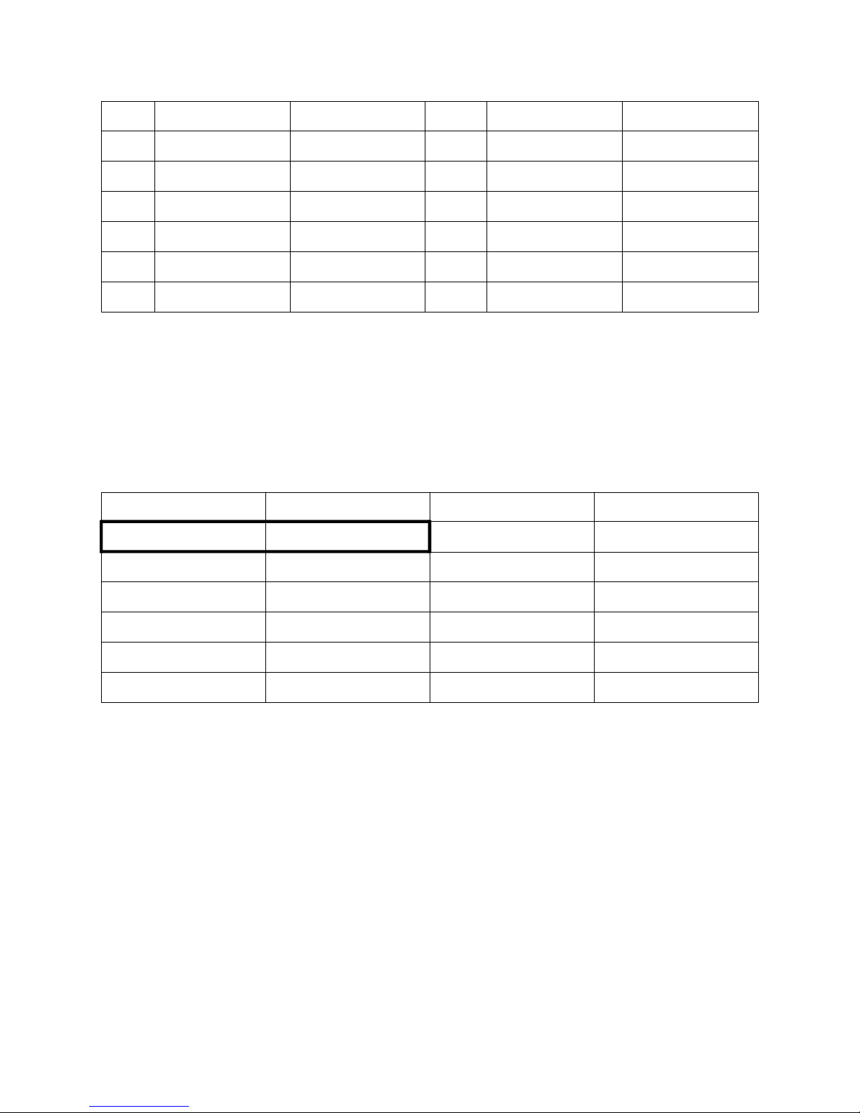
Calibration: Complies with BS4937, NBS125 and IEC584.
Sensor Break Protection: Break detected within two seconds. Control outputs
set to OFF (0% power); Alarms operate as if the
process variable has gone over-range.
Resistance Temperature Detector (RTD) and DC mV: Ranges selectable
from front panel:
Input Range Displayed Code Input Range Displayed Code
0 - 800 °C *
7220
0.0 - 100.9°C
2295
32 - 1471°F
32 - 571°F
-100.9 - 100.0°C
-149.7 - 211.9°F
0 - 300 °C
7221
2229
2230
2231
2251
32.0 - 213.6 °F
-200 - 206°C
-328 - 402°F
-100.9 - 537.3°C
-149.7 - 999.1°F
2296
2297
2298
7222
7223
* Default
Type and Connection: Three-wire Pt100
Calibration: Complies with BS1904 and DIN43760.
Lead Compensation: Automatic scheme.
RTD Sensor Current: 150µA (approximately)
Sensor Break Protection: Break detected within two seconds. Control outputs
set to OFF (0% power). For RTD input, alarms operate
as if the process variable has gone under-range. For
DC (mV) input, alarms operate as if the process
variable has gone over-range.
B-2
Page 71
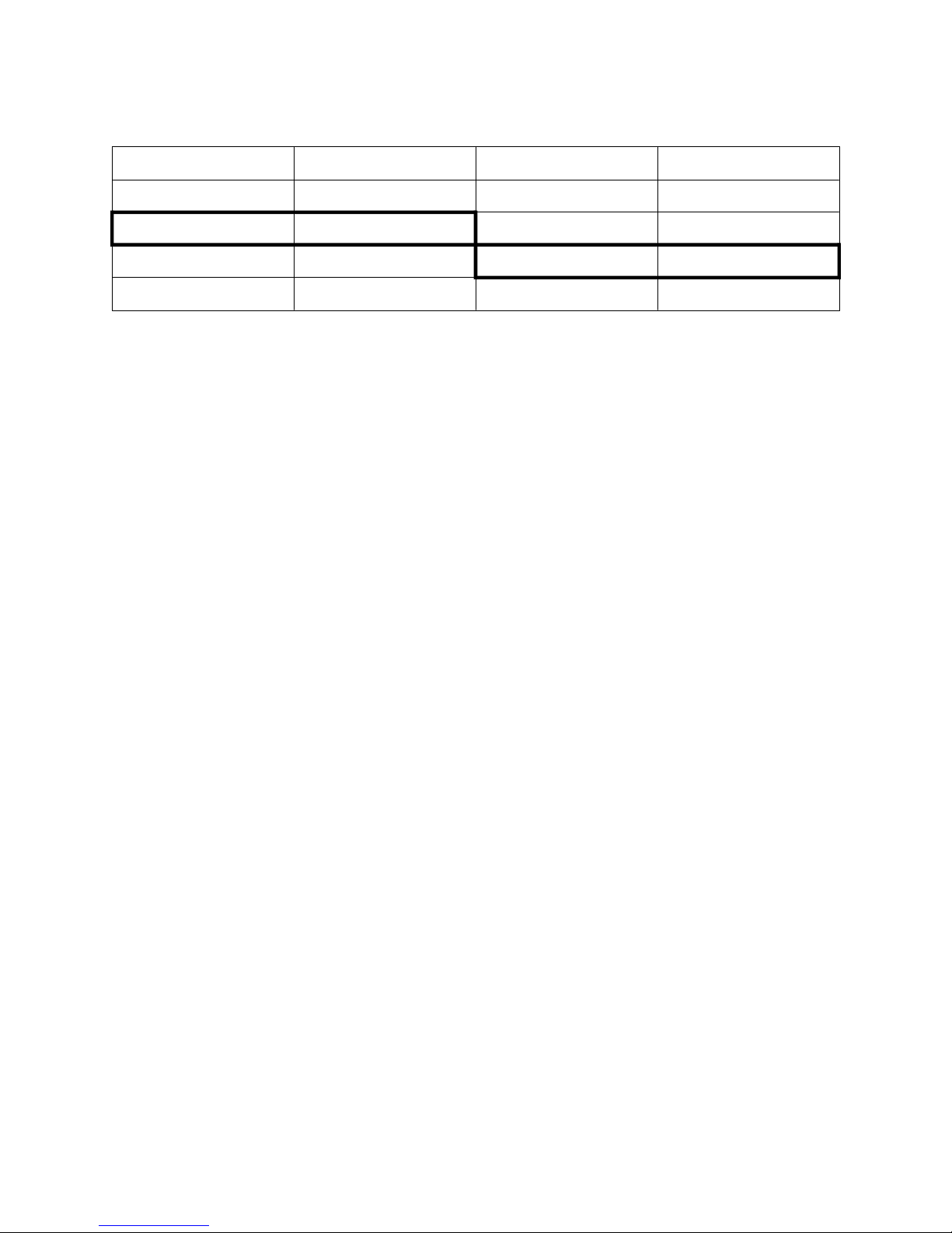
DC Linear: Ranges Selectable from Front Panel:
Input Range Displayed Code Input Range Displayed Code
0 - 20mA 3413 0 - 5V 4445
4 - 20mA * 3414 1 - 5V 4434
0 - 50mV 4443 0 - 10V * 4446
10 - 50mV 4499 2 - 10V 4450
* Default
(Changes may also be required to the CPU PCB link jumpers - see Subsection 7.5.1)
Scale Range Maximum: –1999 to 9999. Decimal point as required.
Scale Range Minimum: –1999 to 9999. Decimal point as for Scale
Range Maximum.
Minimum Span: 1 display LSD.
Sensor Break Protection: Applicable to 4 - 20mA, 1 - 5V and 2 - 10V
ranges only. Break detected within two
seconds. Control outputs set to OFF (0%
power); Alarms operate as if the process
variable has gone under-range.
REMOTE RUN/HOLD INPUT (OPTION)
Type: Voltage-free or TTL-compatible;
edge-sensitive.
OFF-ON transition - currently-selected program
will run or (if currently held) resume running.
ON-OFF transition - currently-running program
will be held.
Voltage-Free Operation: Connection to contacts of external switch or
relay; contacts open = OFF (minimum contact
resistance = 5000Ω ), contacts closed = ON
(maximum contact resistance = 50 Ω ).
TTL levels: OFF: –0.6V to 0.8V
ON: 2.0V to 24V
B-3
Page 72

Maximum Input Delay
(OFF-ON):
1 second
Minimum Input Delay
1 second
(ON-OFF):
OUTPUT 1
General
Types Available: Relay (as standard), DC Pulse, AC SSR and DC
as options.
Relay
Contact Type: Single pole double throw (SPDT).
Rating: 2A resistive at 120/240V AC.
Lifetime: >500,000 operations at rated voltage/current.
Isolation: Inherent.
DC Pulse/TTL
Drive Capability: SSR >4.2V DC into 1k Ω minimum.
Isolation: Not isolated from input or other SSR outputs.
AC SSR
Operating Voltage Range: 20 - 280Vrms (47 - 63Hz)
Current Rating:
Max. Non-repetitive Surge
Current (16.6ms):
Min. OFF-State
dv
@ Rated
dt
Voltage:
Max. OFF-State leakage @
Rated Voltage:
0.01 - 1A (full cycle rms on-state @ 25°C);
derates linearly above 40 °C to 0.5A @ 80 °C.
25A peak
500V/µs
1mA rms
B-4
Page 73

Max. ON-State Voltage Drop
@ Rated Current:
1.5V peak.
Repetitive Peak OFF-state
Voltage, Vdrm:
600V minimum
DC Analog
Resolution: Eight bits in 250mS (10 bits in 1 second typical,
>10 bits in >1 second typical).
Update Rate: Every control algorithm execution.
Ranges: 0 - 20mA
4 - 20mA
0 - 10V
0 - 5V
(Changes between V and mA ranges also require link jumper movement.)
Load Impedance: 0 - 20mA: 500Ω maximum
4 - 20mA: 500Ω maximum
0 - 10V: 500Ω minimum
0 - 5V: 500Ω minimum
Isolation: Isolated from all other inputs and outputs.
Range Selection Method: Link jumper or DIP switch and front panel
code.
OUTPUT 2
General
Types Available: Relay, DC Pulse, AC SSR and DC.
Relay
Contact Type: Single pole double throw (SPDT).
Rating: 2A resistive at 120/240V AC.
Lifetime: >500,000 operations at rated voltage/current.
Isolation: Inherent.
B -5
Page 74

DC Pulse/TTL
Drive Capability: SSR >4.2V DC into 1k Ω minimum.
Isolation: Not isolated from input or other SSR outputs.
AC SSR
Operating Voltage Range: 20 - 280Vrms (47 - 63Hz)
Current Rating:
0.01 - 1A (full cycle rms on-state @ 25°C);
derates linearly above 40 °C to 0.5A @ 80 °C.
Max. Non-repetitive Surge
25A peak
Current (16.6ms):
Min. OFF-State
dv
@ Rated
dt
500V/µs
Voltage:
Max. OFF-State leakage @
1mA rms
Rated Voltage:
Max. ON-State Voltage Drop
1.5V peak.
@ Rated Current:
Repetitive Peak OFF-state
600V minimum
Voltage, Vdrm:
DC Analog
Resolution: Eight bits in 250mS (10 bits in 1 second typical,
>10 bits in >1 second typical).
Update Rate: Every control algorithm execution.
Ranges: 0 - 20mA
(Changes between V and mA ranges also require link jumper movement.)
Load Impedance: 0 - 20mA: 500Ω maximum
B -6
4 - 20mA
0 - 10V
0 - 5V
4 - 20mA: 500Ω maximum
Page 75

0 - 10V: 500Ω minimum
0 - 5V: 500Ω minimum
Isolation: Isolated from all other inputs and outputs.
Range Selection Method: Link jumper or DIP switch and front panel
code.
OUTPUT 3
General
Types Available: Relay, DC Pulse, DC linear (Recorder Output
only)
Relay
Contact Type: Single pole double throw (SPDT).
Rating: 2A resistive at 120/240V AC.
Lifetime: >500,000 operations at rated voltage/current.
Isolation: Inherent.
DC Pulse/TTL
Drive Capability: SSR >4.2V DC into 1k Ω minimum.
Isolation: Not isolated from input or other SSR outputs.
DC Analog
Resolution: Eight bits in 250mS (10 bits in 1 second typical,
>10 bits in >1 second typical).
Update Rate: Every control algorithm execution.
Ranges: 0 - 20mA
4 - 20mA
0 - 10V
0 - 5V
(Changes between V and mA require link jumper movement.)
B -7
Page 76

Load Impedance: 0 - 20mA: 500Ω maximum
4 - 20mA: 500Ω maximum
0 - 10V: 500Ω minimum
0 - 5V: 500Ω minimum
Isolation: Isolated from all other inputs and outputs.
Range Selection Method: Link jumper or DIP.
LOOP CONTROL
Automatic Tuning Types: Pre-Tune
Proportional Bands: 0 (OFF), 0.5% - 999.9% of input span at 0.1%
increments.
Reset (Integral Time Constant): 1s - 99min 59s and OFF
Rate (Derivative Time
0 (OFF) - 99 min 59 s.
Constant):
Manual Reset (Bias): Added each control algorithm execution.
Adjustable in the range 0 - 100% of output
power (single output) or –100% to +100% of
output power (dual output).
Deadband/Overlap: –20% to +20% of Proportional Band 1 +
Proportional Band 2.
ON/OFF Differential: 0.1% to 10.0% of input span.
Auto/Manual Control: User-selectable with “bumpless” transfer into
and out of Manual Control.
Cycle Times: Selectable from
1
s to 512 secs in binary steps.
2
Setpoint Range: Limited by Range Maximum and Range
Minimum.
ALARM CONTROL
Maximum Number of Alarms: Two “soft” alarms.
Max. No. of Outputs Available: Up to two outputs can be utilised for alarm
B-8
purposes.
Page 77

Combinatorial Alarms: Logical OR or AND of alarms to an individual
hardware output is available.
PERFORMANCE
Reference Conditions
Generally as EN60546-1.
Ambient Temperature:
20°C ±2oC
Relative Humidity: 60 - 70%
Supply Voltage: 90 - 264V AC 50Hz 1%
Source Resistance: <10Ω for thermocouple input
Lead Resistance: <0.1Ω/lead balanced (Pt100)
Performance Under Reference Conditions
Common Mode Rejection: >120dB at 50/60Hz giving negligible effect at
up to 264V 50/60Hz.
Series Mode Rejection: >500% of span (at 50/60Hz) causes negligible
effect.
DC Linear Inputs
Measurement Accuracy:
±0.25% of span ±1LSD.
Thermocouple Inputs
Measurement Accuracy:
Linearisation Accuracy:
Cold Junction Compensation:
±0.25% of span ±1LSD. NOTE: Reduced
performance with Type “B” Thermocouple
between 100 - 600 °C (212 - 1112 °F).
Better than ±0.2 °C any point, any 0.1°C range
(±0.05°C typical). Better than ±0.5 °C any
point, any 1 °C range.
Better than ±0.7 °C.
B-9
Page 78

RTD Inputs
Measurement Accuracy:
Linearisation Accuracy:
DC Outputs - Accuracy
Output 1:
Output 2:
Output 3 (Recorder Output):
Operating Conditions
Ambient Temperature
(Operating):
±0.25% of span ±1LSD
Better than ±0.2 °C any point, any 0.1°C range
(±0.05°C typical). Better than ±0.5 °C any
point, any 1 °C range.
±0.5% (mA @ 250Ω, V @ 2kΩ ); 2% underdrive
(4 - 20mA) and overdrive applies.
±0.5% (mA @ 250Ω, V @ 2kΩ ); 2% underdrive
(4 - 20mA) and overdrive applies.
±0.25% (mA @ 250 Ω, V @ 2kΩ ); Degrades
linearly to ± 0.5% for increasing burden (to
specification limits).
0 °C to 55 °C
Ambient Temperature
–20 °C to 80°C
(Storage):
Relative Humidity: 20% - 95% non-condensing
Supply Voltage: 90 - 264V AC 50/60Hz (standard)
20 - 50V AC 50/60Hz or 22 - 65V DC (option)
Source Resistance: 1000 Ω maximum (thermocouple)
Lead Resistance: 50Ω per lead maximum balanced (Pt100)
Performance Under Operating Conditions
Temperature Stability:
0.01% of span/°C change in ambient
temperature.
Cold Junction Compensation
Better than ±1°C.
(thermocouple Only):
B-10
Page 79

Supply Voltage Influence: Negligible.
Relative Humidity Influence: Negligible
Sensor Resistance Influence: Thermocouple 100Ω : <0.1% of span error
Thermocouple 1000Ω : <0.5% of span error
RTD Pt100 50 Ω/lead: <0.5% of span error
ENVIRONMENTAL
Operating Conditions:
See PERFORMANCE.
Approvals: CE, UL, cUL
EMI Susceptibility: Certified to EN50082-1:1992 and
EN50082-2:1995.
NOTE: For line-conducted disturbances
induced by RF fields (10V 80% AM 1kHz), the
product is self-recoverable in the frequency
bands 17 - 47MHz and 68 - 80MHz.
EMI Emissions: Certified to EN50081-1:1992 and
EN50081-2:1994.
Safety Considerations: Complies with EN61010-1:1993.
Supply Voltage: 90 - 264V AC 50/60Hz (standard)
20 - 50V AC 50/60Hz or 22 - 65V DC (option)
Power Consumption: 4 watts approximately.
Front Panel Sealing: To IP66 (NEMA 4).
PHYSICAL
Dimensions: Depth - 110mm
Front Panel: Width - 48mm, Height - 48mm (1/16 DIN)
Mounting: Plug-in with panel mounting fixing strap. Panel
Terminals: Screw type (combination head).
Weight: 0.21kg maximum
cut-out 45mm x 45mm.
B-11
Page 80
APPENDIX C SUMMARY OF DISPLAYS
The lower display on the Controller Programmer front panel is used to identify the
parameter being displayed. The parameter identifiers are as follows:
Legend Meaning Section
Base Mode Parameters
Manual Power (xxx = power output value)
Setpoint
Delayed Start
Final (Target) Setpoint for Segment xx (01 - 16)
Time remaining
Cycles remaining
Automatic/Manual Control selection
Event/Alarm Status
Current Program (1 - 4)
Controller Set-Up Mode Parameters
Input Filter Time Constant
Process Variable Offset
Output 1 Power (0 - 100%)
Output 2 Power (0 - 100%)
1.12
1.1
1.2
1.6
1.6
1.6
1.6
1.6
1.6
4.1
4.1
4.1
4.1
Proportional Band 1
Proportional Band 2
Reset (Integral Time Constant)
Rate (Derivative Time Constant)
Deadband/Overlap
Bias (Manual Reset)
ON/OFF Differential (both outputs)
ON/OFF Differential (Output 1 only)
ON/OFF Differential (Output 2 only)
Setpoint Lock
C-1
4.1
4.1
4.1
4.1
4.1
4.1
4.1
4.1
4.1
4.1
Page 81
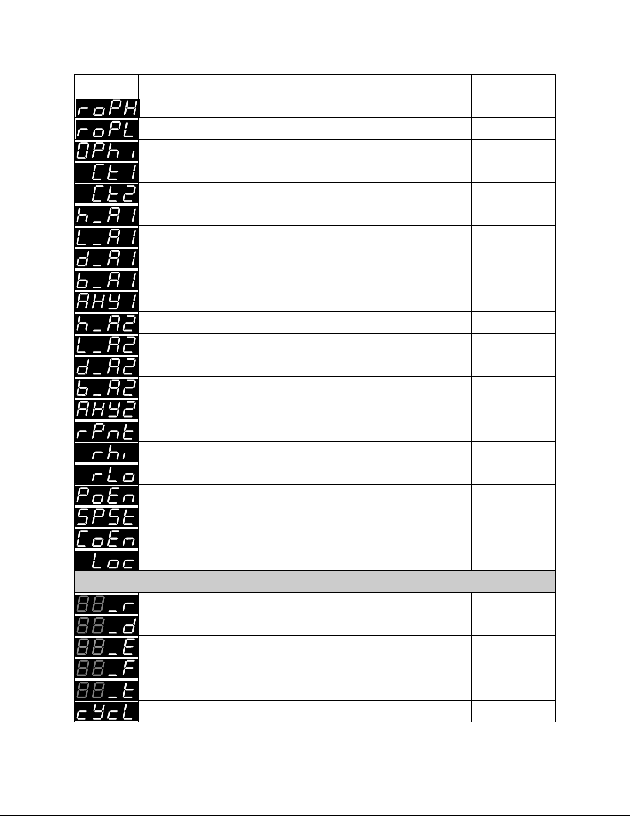
Legend Meaning Section
Recorder Output Scale Maximum
Recorder Output Scale Minimum
Output Power Maximum
Output 1 Cycle Time
Output 2 Cycle Time
Process High Alarm 1 value
Process Low Alarm 1 value
Deviation Alarm 1 value
Band Alarm 1 value
Alarm 1 Hysteresis value
Process High Alarm 2 value
Process Low Alarm 2 value
Deviation Alarm 2 value
Band Alarm 2 value
4.1
4.1
4.1
4.1
4.1
4.1
4.1
4.1
4.1
4.1
4.1
4.1
4.1
4.1
Alarm 2 Hysteresis value
Decimal Point Position (for linear input range)
Range Maximum (for linear input range)
Range Minimum (for linear input range)
Manual Power Selection enable/disable
Setpoint Strategy
Communications Write enable/disable
Lock Code
Program Define Mode Parameters
Ramp Rate for egment xx (xx in range 01 - 16)
Segment xx is currently set as a Dwell segment
Segment xx is currently set as an End segment
Final (Target) Setpoint value for Segment xx
Segment Time for Segment xx
4.1
4.1
4.1
4.1
4.1
4.1
4.1
4.1
3.2.2
3.2.2-3
3.2.2-3
3.2.2-3
3.2.2-3
Number of Cycles Programmed
3.2.4
C-2
Page 82
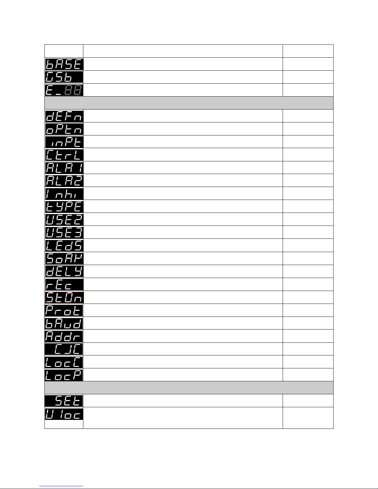
Legend Meaning Section
Timebase (hours/minutes or minutes/seconds)
Guaranteed Soak Band value
Event Marker setting for Segment xx
Configuration Mode Parameters
Hardware Definition Code
Hardware Option selection
Input Type selection
Control Action
Alarm 1 Type
Alarm 2 Type
Alarm Inhibit
Program Mode (Rate or Time)
Output 2 Usage
Output 3 Usage
3.2.4
3.2.4
3.2.4
6.2
6.3
6.4
6.4
6.4
6.4
6.4
6.4
6.4
6.4
LED Usage (∆ and ∇ )
Guaranteed Soak Action
Delayed Start enable/disable
Power Fail Recovery (Warm Start/Cold Start)
Program Start Setpoint (current PV/controller SP)
MODBUS parity selection
Communications Baud rate
Communications Address (Zone)
Cold Junction Compensation enable/disable
Controller Set-Up Mode Lock Code
Program Define Mode Lock Code
Miscellaneous
Entry to Controller Set-Up Mode or Program Define Mode
User to enter lock code to access either Controller Set-Up
Mode or Program Define Mode
6.4
6.4
6.4
6.4
6.4
6.4
6.4
6.4
6.4
6.4
4.1 & 3.1
4.1 & 3.1
C-3
Page 83

ALPHABETICAL INDEX
A
Aborting a Program 1-2
Active Program Setpoint
Display of 1-3
Alarm 1 Hysteresis 4-4
Alarm 1 Status
Display of 1-1, 1-3
Alarm 1 Type 6-4
Alarm 2 Hysteresis 4-5
Alarm 2 Status
Display of 1-1, 1-3
Alarm 2 Type 6-5
Alarm Hysteresis
Description of 4-8
Alarm Inhibit 6-5
Alarm Operation
Description of 4-7
Automatic Control
Selection of 1-7
Communications Baud Rate
Selection of 6-8
Communications Protocol
Selection of 6-8
Configuration Mode
Entry into 6-1
Exit from 6-9
Control Mode
Display of 1-1, 1-3
Controller Dimensions B-11
Controller Set-Up Mode
Entry into 4-1
Exit from 4-9
Controller Set-Up Mode Lock Code
Display of 6-9
Cycles Remaining
Display of 1-3
Cyclic Redundancy Checksum
Description of 5-5
B
Band Alarm 1 4-4
Band Alarm 2 4-5
Baud Rates Available 5-1
Bias 4-3
Bit Parameters 5-7
Broadcast Messages 5-2
C
Cold Junction Compensation
Enabling/disabling 6-9
Communications
Enabling/disabling 4-5
Communications Address
Selection of 6-8
D
Data Format 5-2
Deadband 4-3
Description of 4-6
Delay Time
Selection of 1-2
Delayed Start
Enabling/disabling 6-8
Derivative Time Constant 4-3
Deviation Alarm 1 4-4
Deviation Alarm 2 4-5
1
Page 84

E
I
Error Responses 5-5
Event Markers
Defining 3-5
Event Output Status
Display of 1-1, 1-3
Exception Codes 5-5
Exception Responses 5-5
F
Final Setpoint
Display of 1-3
Fuse Rating
24V AC/DC supply 2-4
Mains supply 2-4
G
Guaranteed Soak
Enabling/Disabling/Manual
6-8
Guaranteed Soak Band
Defining 3-5
Description of 3-6
H
Hardware Definition Code
Adjustment of 6-1
Display of 1-6, 6-1
Explanation of 1-6
Input/Output Type selection
6-3
Holding a Program 1-2
Input Connections
Linear input 2-5
Remote Run/Hold input 2-5
RTD 2-4
Thermocouple 2-4
Input Filter Time Constant 4-3
Input Range 6-4
Input Type
Selection of 7-4
Integral Time Constant 4-3
L
LEDs Usage 6-8
Lock Code (Controller Set-Up Mode)
4-5
Lock Code (Program Define Mode)
Defining 3-5
Logical Combination of Alarms
Example (AND) 6-7
Example (OR) 6-6
M
Making a Soak Segment
Rate Mode 3-3
Time Mode 3-4
Making a Ramp Segment
Rate Mode 3-3
Time Mode 3-4
Making an End Segment
Rate Mode 3-3
Time Mode 3-4
Manual Control
Selection of 1-7
Manual Control Selection
Enabling/disabling 4-5
2
Page 85

Manual Guaranteed Soak
Description of 3-6
Manual Reset 4-3
Message formats 5-2
Message termination 5-2
N
Number of Cycles
Defining 3-5
O
ON/OFF Differential 4-4
Description of 4-6
Option Selection 6-3
Output 1 Action 6-4
Output 1 Cycle Time 4-4
Output 1 Power Limit 4-4
Output 1 Type
Selection of 7-5
Output 2 Cycle Time 4-4
Output 2 Type
Selection of 7-6
Output 2 Usage 6-6
Output 2/Output 3 Option PCB
Removal/replacement 7-3
Output 3 Type
Selection of 7-6
Output 3 Usage 6-7
Output Connections
DC 2-6
Relay 2-5
Output Power 1 4-3
Output Power 2 4-3
Overlap 4-3
Description of 4-6
P
Panel-mounting
Procedure 2-2
Panel-Mounting
Cut-out dimensions
(multiple installation) 2-1
Cut-out dimensions
(single installation)2-1
Maximum panel thickness
2-1
Programmer/Controller dimensions
2-1
Panel-mounting the
Programmer/Controller 2-1
PCB Positions 7-1
Power Loss Recovery
Cold start/Hot start 6-8
Pre-Tune
Dis-engaging 1-4
Engaging 1-4
Pre-Tune Facility
Activation of 1-4
Pre-Tune Status
Indication of 1-5
Process High Alarm 1 4-4
Process High Alarm 2 4-5
Process Low Alarm 1 4-4
Process Low Alarm 2 4-5
Process Variable
Display of 1-1
Process Variable Offset 4-3
Program Definition Mode
Entry into 3-1
Exit from 3-9
Program Mode
Selection of 6-5
Program Number
Display of 1-1,1-3
Selection of1-1 - 1-2
Programmer Commands5-11
3
Page 86

Programmer Status Byte 5-11
Proportional Band
Description of 4-6
Proportional Band 1 4-3
Proportional Band 2 4-3
R
RaPID Control
Dis-engaging 1-4
RaPID Control Status
Indication of 1-5
Rate 4-3
Rear Terminal Connections 2-2
Recorder Output Scale Maximum
4-4
Recorder Output Scale Minimum
4-4
Releasing a Currently-Held Program
1-2
Remote Run/Hold Option PCB
Removal/replacement 7-3
Replacing the Instrument in its Housing
7-3
Reset 4-3
RS485 Communications Option PCB
Removal/replacement 7-3
Sensor Break
Effect on outputs
(DC linear inputs) B-3
Effect on outputs
(RTD inputs) B-2
Effect on outputs
(thermocouple inputs) B-2
Serial Communications Connections
2-6
Setpoint Adjustment (in Base Mode)
Enabling/disabling 4-4
Setpoint Lock 4-4
Setpoint Strategy 4-5
Supply Connections
24V AC/DC Option 2-4
Mains (Line) voltage 2-4
T
Time Remaining
Display of 1-3
Timebase
Selection of 3-5
U
Unpacking Procedure 2-1
Unpacking the Instrument 2-1
S
Scale Range Decimal Point Position
4-5
Scale Range Maximum 4-5
Scale Range Minimum 4-5
Segment Event Status
Description of 3-7
4
W
Word Parameters 5-8
Page 87
Page 88
Page 89
Page 90
Page 91
Page 92
Page 93
Page 94
Page 95
Page 96
Page 97

Page 98

Sensing and Contr ol
Honeywell
11 West Spring Street
Freeport, IL 61032
57-77-25-17 0300 Printed in USA www.honeywell.com/sensing
 Loading...