


Timer Thermostat
Fuel Saver
Heating-Only Thermostat and Wallplate or Heating/Cooling Thermostat and Subbase Models CT1500, CT1501, CT1502, CT1503
•Heat Only—CT1500
•Heat/Cool—CT1501
•Central Electric Heat/Cool or Single Stage Heat Pump without auxiliary heat—CT1502
•Millivolt Heat—CT1503
OWNER’S MANUAL
69-0333-6
Welcome to the world of energy savings with your new Honeywell Fuel Saver Thermostat. The Honeywell name is your assurance of accurate control and reliable operation for years to come.
Your new thermostat will automatically control the temperature in your home to provide a high level of comfort plus energy savings when programmed according to the instructions in this manual.
Recycling Notice
This control contains mercury in a sealed tube. Do not place control in the trash at the end of its useful life.
If this control is replacing a control that contains mercury in a sealed tube, do not place your old control in the trash.
Contact your local waste management authority for instructions regarding recycling and the proper disposal of the control, or of an old control containing mercury in a sealed tube.
2 |
69-0333—6 |
Table of Contents |
|
|
PAGE |
Features of Your Thermostat .............................................................................................. |
4 |
Reviewing Your Family Schedule ....................................................................................... |
7 |
Setting The Temperature .................................................................................................... |
8 |
Setting Subbase Switches .................................................................................................. |
9 |
Inserting Timer Batteries ................................................................................................... |
10 |
Setting The Timer.............................................................................................................. |
11 |
Programming ..................................................................................................................... |
12 |
Temporarily changing the program .............................................................................. |
15 |
Troubleshooting ................................................................................................................ |
17 |
Servicing The Thermostat ................................................................................................. |
21 |
System on-time adjustment .......................................................................................... |
21 |
Thermometer adjustment ............................................................................................. |
22 |
Limited One-Year Warranty .............................................................................................. |
27 |
3 |
69-0333—6 |
Features of Your Thermostat |
2 |
|
1 |
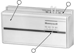
1 FLIP-UP COVER. Lift up cover to set timer for energy savings and normal temperature periods .
2 THERMOSTAT COVER. Lift up cover and remove to adjust heat anticipator or install batteries.
3THERMOMETER. Provides accurate room temperature reading.
4TIMER. Provides 24-hour slotted dial to hold the programming pins.
5TIMER SETTING KNOB. Turn clockwise
to match the correct a.m. or p.m. time to |
3 |
M8750
the time indicator.
6TIME INDICATOR. Arrowhead indicates time for 24-hour dial.
7PROGRAM INDEX WHEEL. Controls high and low temperature at specific time of day as set by program pins. Can be moved to temporarily override a schedule.
4 |
69-0333—6 |
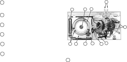
8TEMPERATURE SETTING LEVERS. Left (blue mark) controls the low temperature; right (red mark) controls the high temperature.
9PROGRAM PINS. Must be inserted into
24-hour timer dial slots to control program index wheel.
10PIN SLOTS. Located on 24-hour dial at ten minute intervals for program pin insertion.
11HEAT ANTICIPATOR SCALE PLATE. Calibrated to match the heating system current draw in amperes.
12ANTICIPATOR SETTING LEVER. Must be adjusted to match the heating system primary control current.
13BULB AND BIMETAL ELEMENT (2). Provides automatic temperature control by switching the heating or cooling system on and off.
8
14 |
5 |
4 |
13
9 |
10 |
7 |
6 |
11 |
12 |
M8749 |
14AAA ALKALINE BATTERIES (2). Included to provide power to the timer.
5 |
69-0333—6 |

15WALLPLATE Provides mounting base and wiring connections for heating-only thermostat.
16SUBBASE Provides mounting base, wiring connections and manual switching control for heating/cooling thermostat.
15 |
M2421 |
16
6
O
B
R
W
G
Y
FAN |
AUTO |
HEAT |
COOL |
ON |
OFF |
M2411
69-0333—6
Reviewing Your Family Schedule
Write the answers to the following questions in the spaces provided to determine the program that fits your family schedule.
|
SUMMER |
WINTER |
What comfort temperature would you like to maintain? |
___________ |
__________ |
What energy savings temperature would you like to maintain? |
___________ |
__________ |
What time does the first person get up in the morning? |
___________ |
__________ |
Is anyone home all day? |
___________ |
__________ |
What times does the last person leave in the morning? |
___________ |
__________ |
What times does the first person return home in the evening? |
___________ |
__________ |
What time does the last person go to bed? |
___________ |
__________ |
7 |
69-0333—6 |
Setting The Temperature
For Heating:
Set the left lever (blue mark) to the energy savings temperature you want when you are sleeping or your home is unoccupied. See Fig. 1.
Set the right lever (red mark) to the temperature you want for normal comfort periods.
NOTE: You may bypass the time program by setting both the red and blue levers to the same temperature setpoint.
For Cooling (Not Applicable on Heating-only Model):
Set the left lever (blue mark)to the temperature you want for normal comfort periods.
Set the right lever (red mark) to the energy savings temperature you want when you are sleeping or your home is unoccupied.
LOW TEMPERATURE |
|
|
HIGH |
|
|
TEMPERATURE |
|
SETTING LEVER |
|
|
|
|
|
SETTING |
|
(BLUE MARK) |
|
|
|
|
|
LEVER |
|
|
|
|
|
|
|
|
(RED MARK) |
50 |
60 |
70 |
80 |
50 |
60 |
70 |
80 |
M8751
Fig. 1—Setting high and low temperature setting levers.
8 |
69-0333—6 |
Setting Subbase Switches
(If Applicable)
The subbase system switch controls system operation as follows:
HEAT—Heating system is controlled by the thermostat. Cooling system is off.
COOL—Cooling system is controlled by the thermostat. Heating system is off.
OFF—Both the heating and cooling systems are off. If the fan switch is in the AUTO position, the fan is also off.
ON—In a cooling only application, only cooling operates. In a heating only application, only heating operates.
The subbase fan switch controls fan operation as follows:
ON—Fan operates continuously. AUTO—Fan operates with cooling equip-
ment as controlled by the thermostat or with the heating equipment as controlled by the plenium fan switch. In electric heat, heat pump, and fan coil systems, the fan is controlled by the thermostat in heating and cooling.
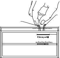
To switch positions, use thumb or index finger to slide lever to desired position. Stop switch lever in detent over the desired function indicator mark for proper circuit operation.
9 |
69-0333—6 |
 Loading...