

Honeywell CAMIR-N Installation Instructions Manual
- 1 -
LED
Status
Condition
Enabled
Activée
Disabled
Désactivée
Warm-up (~2.5 min.)
Chauffe (~2.5 min)
Slow blink
Flash lent
Slowb link
Flash lent
Detection
Détection
Short illumination
Allumage court
NO LED
AUCUN LED
Alarm
Alarme
Long illumination
Allumage long
NO LED
AUCUN LED
TAKING A PICTURE AFTER ENTERING TEST MODE PRISE DE PHOTO A L’ENTREE DU
MODE TEST
TIME TEMPS 12 sec 3 sec 1 sec 15 sec
LED
Slow blink
Flash lent
Fast blink
Flash rapide
LED ON LED
ILLUMINE
NO LED
AUCUN LED
MESSAGE
Preparing to take
a picture Préparation
à la prise de photo
Picture is going
to be taken
Photo va être
prise
Picture is
taken
Photo est
prise
Restart / no
test Relancer
/ aucun test
CT
WT
Lw = Lower 18-20
Lw = Faible portée18-20
IM = Intermediate 12-17
IM = Portée Intermediaire 12-17
L = Long 1-11
L = Longue portée 1-11
2,3m - 2,7m
(7,
5ft –9ft
)
CT = Corner Tamper / Autoprotection d'angle
WT = Wall Tamper / Autoprotection murale
Languette d'autoprotection à l'arrachement. Le montage
est plus fiable s'il est réalisé sur un montant, une pièce
de bois solide ou avec une fixation murale robuste /
Rear Tamper a robust wall anchor
7’
2 m
Lowe
r
18-20
13’
4 m
20
'
6 m
27’
8 m
L
ong
35'
11 m
I
nterme
diate
12-17
1-11
7'6"
(
2.3 m
)
CAMIR-N: Installation Instructions / Manuel d’installation (ENGLISH/FRANCAIS)

CAMIR-N: PIR Sensor with Night Vision Came ra–Installation Instructions (ENGLISH
)
1. Introduction
This volumetric sensor uses passive infra-red technology, and has a
built in night vision camera. The CAMIR-N sensor is part of the range of
radio peripherals used with the Domonial 800++ control panels.
Special Instructions for Installing with Pets
To take full advantage of the pet immunity in the CAMIR-N sensor,
follow the guidelines below:
• Set the sensor to the Low sensitivity setting as required by the
application.
• At Low sensitivity setting, the total combined weight of animals may
not exceed 36 kg (80 lb).
• Mount the sensor where pets cannot come within 1.80 m
(6 feet) of the sensor by climbing on furniture, boxes
or other objects.
• Do not aim the sensor at stairways or furniture/objects that can be
climbed on by animals.
• Environmental differences and the amount of heat radiated by an
animal will vary the animal immunity levels exhibited by the sensor.
Sensor must have a clear line-of-sight to protected area (see figure 1
for mounting location recommendations). Each installation should be
tested to determine the exact level of animal immunity attainable.
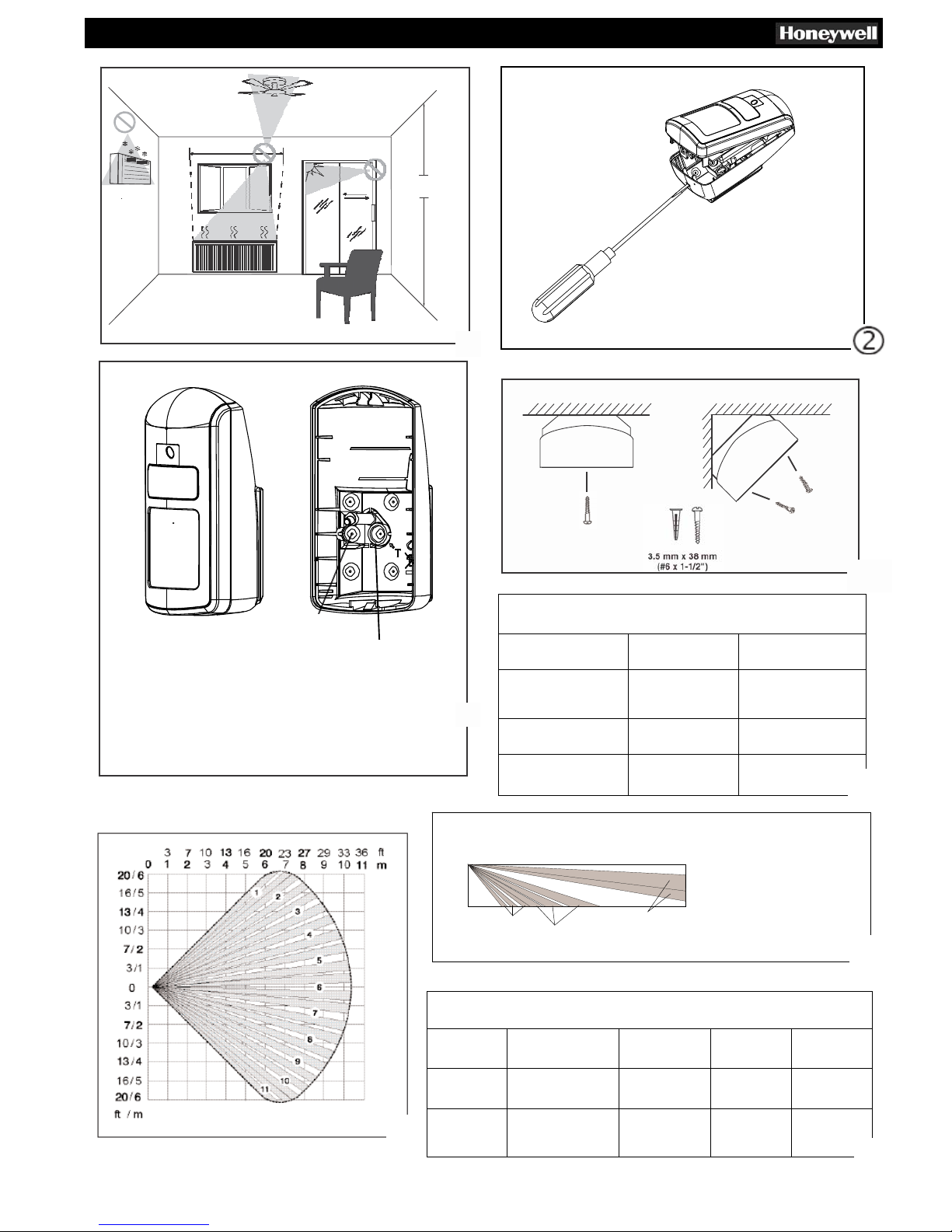
2. Mounting
Tamper Switches
The CAMIR-N sensor is equipped with a normally-closed cover tamper.
This tamper opens when the cover is opened.
Two wall tampers are provided:
• Operational when the sensor is fixed flat against a wall.
• On one angle, operational when the sensor is fixed at an angle (see
Figure 4).
Mounting Instructions
• Using a small screwdriver, push in the housing latch at the bottom
of the sensor and gently remove the front cover, lifting it from the
bottom.
• Hold the batteries in place, and pull out the battery tab to power up
the sensor. You can register the sensor immediately or at a later
time.
• Mount the rear housing flat against a wall or in a corner
using screws placed in the mouting holes (see Figure 4).
3. LED operation
Use the configuration tool to enable the alarm LED (see Figure 5).
4. Registration
Registration on a Domonial
panel
Registration is the procedure that associates the detector with the
control panel. This operation requires a programming tool based on
PDA or PC, or the TCU keypad. The complete procedure is described
in the user manuals of these tools.
• Connect the programming tool to the control panel and
enter programming mode.
• Select the item Add New Device.
• Remove the battery tab or activate the tamper by opening and
closing the cover of the sensor. A confirmation message appears
after several seconds, indicating the registration of the sensor
at the control panel, together with the radio signal level and the
serial number of the device.
• Choose the function mode, the label, etc.
Warning: The sensor must always be registered in its
final
position with a minimum radio signal level of 4/10
5. Configuration
The CAMIR-N sensor is configured using a programming tool (PC).
The following settings can be configured:
• LED
• PIR sensitivity
Setting Sensitivity and Testing the Sensor
Set the sensitivity appropriate for the application (see the options
below), and replace the cover. Begin the walk-test as soon as the
LED stops blinking. Walk through the detection zone(s), observing
the sensor’s LED. The LED indicates detection of movement and
transmission of an alarm.
The absolute range of a sensor unit is subject to variation due to
different clothing types, backgrounds and ambient temperature.
For this reason, you should ensure that the most likely intruder
routes are well within the sensor’s detection zones, and that walktesting is carried out along those routes.
Sensitivity Options
• Low Sensitivity: 3-5 steps. This is the recommended setting for
applications with pets up to 36 kg.
• Medium Sensitivity. 1-3 steps.
• High Sensitivity: 1-2 steps. This is the recommended setting for
any location where an intruder is expected to cross only a small
portion of the area covered. Recommended for High Security
applications (Conforms to EN50131).
Note: The distances in the detection pattern illustrations are only
given as a guide, and do not represent the
maximum
detection
distances
6. Walk-Test Mode
After the warm-up period (2 min 30 sec), when the cover is closed
(operation of the tamper switch) the product enters into test mode for
10 minutes. This test is mandatory to ensure proper detection. Each
detection results in an alarm signal being sent. To restart the 10minute test period, operate the tamper switch by opening and closing
the cover. Immediately after entering test mode, you can take photos
with the programming tool upon operation of the tamper (providing
there is no battery fault), see figure 7.
7. Battery Failure
The sensor signals a battery failure at the control panel when the
battery needs to be replaced. The sensor will continue to operate for
up to one month after this, but the photo functionality will be disabled.
Note: that if the batteries are weak, the photo function of the sensor
will not work.
Battery Removal & Handling Safety Warning: Risk of
fire, explosion and burns. Do not recharge, disassemble,
heat above 100° C, or incinerate the battery. Use care when
changing the battery to ensure that the battery is not damaged
and the terminals are not shorted during removal. If the battery
is damaged, use personal protective equipment to remove it
immediately, and dispose of it in a safe manner (refer to the
battery manufacturers specifications). Comply with applicable
national and local regulations to dispose of deplete d batteries.
For Switzerland, Annex 4.10 of SR 814.013 applies to the battery
included with this product.
For all enquiries, please visit your local Honeywell website.
- 2 -
 Loading...