

Page 1
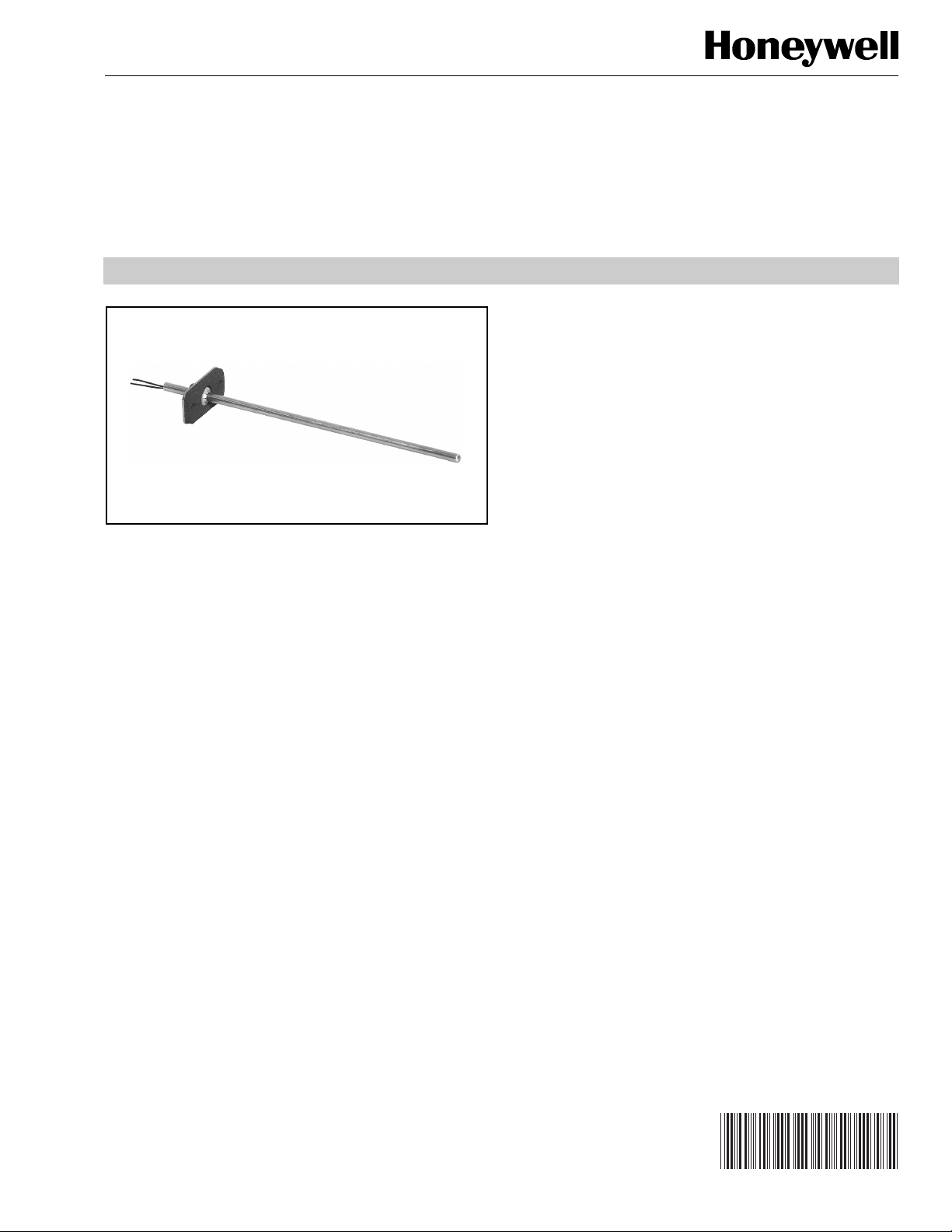
Air Temperature Sensors
APPLICATION
The C7046 series of Air Temperature Sensors function as
primary and/or secondary sensors in electronic control
systems.
C7046A,B,C,D
PRODUCT DATA
FEATURES
• C7046A,C Sensors have probe lengths of 8 in.
(203 mm) and nominal sensor resistance of 3000 ohms
at 77°F (25°C).
• C7046B Sensor has probe length of 6 in. (152 mm) and
nominal sensor resistance of 22,800 ohms at 77°F (25°C).
• C7046D Sensor has probe length of 8 in. (203 mm) and
nominal sensor resistance of 1097 ohms at 77°F (25°C).
• Carbon type, negative temperature coefficient
(NTC) thermistor sensing element in the C7046A,B,C
and platinum thin film, positive temperature coefficient
(PTC) element in C7046D precisely measures
temperature changes.
• No settings or calibration required.
• Solid state components not affected by dust or dirt.
• Fast reacting.
• Rugged stainless steel insertion probe.
• Mounts on duct or plenum surface with mounting
flange or in a 2 in. by 4 in. (51 by 102 mm) junction box.
• C7046B can be used as a replacement for C7100B
Averaging Temperature Sensor where duct or plenum
cross section is less than 13 in. (330 mm).
® U.S. Registered Trademark
© 2004 Honeywell International Inc.
All Rights Reserved
Contents
Application ........................................................................ 1
Features ........................................................................... 1
Specifications ................................................................... 2
Ordering Information ........................................................ 2
Installation ........................................................................ 3
Wiring ............................................................................... 4
Operation and Checkout .................................................. 5
60-2350—8
Page 2
C7046A,B,C,D AIR TEMPERATURE SENSORS
)
D
)
02
(25)
)
)
)
)
)
)8 (
)
GASKET
R
)
USH
)
C
BUS
G
SPECIFICATIONS
IMPORTANT
Specifications given in this publication do not include
normal manufacturing tolerances. Therefore, this unit
may not exactly match the listed specifications. Also,
this product is tested and calibrated under closely
controlled conditions and some minor differences in
performance can be expected if those conditions are
changed.
Models:
C7046A Air Temperature Sensor: Intended for use as a
discharge sensor with the W973 Single Zone Logic Panel.
C7046B Air Temperature Sensor: Intended for use as a zone
discharge, hot deck, cold deck, mixed air and/or return air
sensor in the W7080 Multizone Control System.
C7046C Air Temperature Sensor: Intended for use as a
discharge sensor in rooftop applications.
C7046D Air Temperature Sensor: Intended for use as a
discharge air sensor in the Excel 500 Control System.
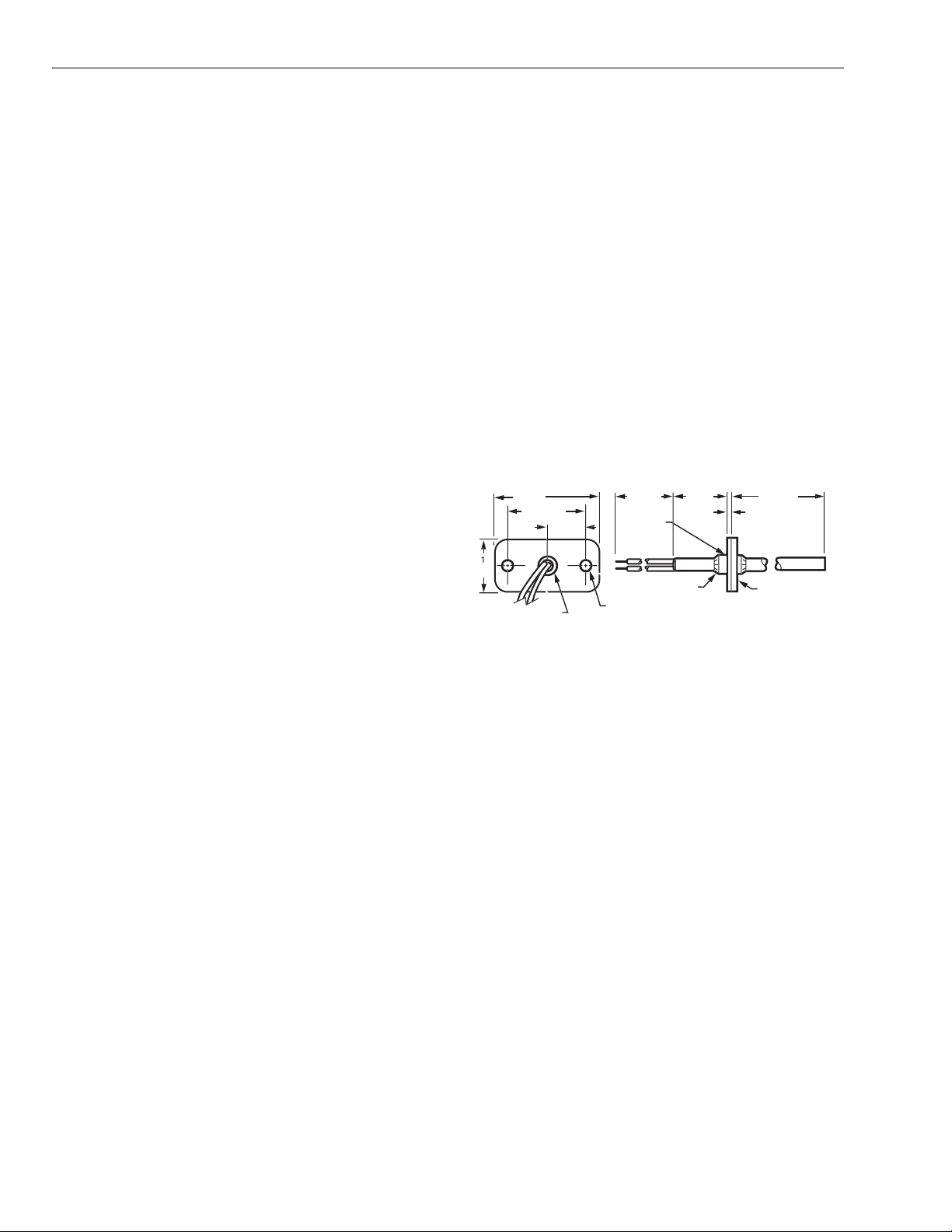
Dimensions: See Fig. 1.
Mounting: Integral mounting flange requiring two No. 8 screws.
Sensing Element:
C7046A,B,C: Carbon type, thermistor-resistor element.
C7046D: Platinum thin film element.
Maximum Ambient Temperature: 250°F (121°C).
Operating Temperature Range: 40 to 150°F (4 to 66°C).
Wiring Connections: 6 in. (152 mm) leadwires.
Performance Characteristics:
Reaction Time Constant with Air Approach Velocity of
500 ft/min (2 m/sec):
C7046A: 100 seconds.
C7046B: 165 seconds.
C7046C: 60 seconds.
C7046D: 130 seconds.
Resistance/Temperature (NTC):
C7046A,C:
Nominal Resistance: 3000 ohms at 77°F (25°C)
Nominal Sensitivity: 70 ohms per degree F (124 ohms
per degree C) at midrange.
C7046B:
Nominal Resistance: 22,800 ohms at 77°F (25°C).
Nominal Sensitivity: 675 ohms per degree F (1290 ohms
per degree C) at midrange.
C7046D:
Nominal Resistance: 1097 ohms at 77°F (25°C).
Nominal Sensitivity: 2.1 ohms per degree F (3.9 ohms
per degree C).
2 (51
1-1/2 (38
5/16 (9) DIAMETE
(BUSHING
3/4 (19
203
PLASTI
HIN
LOCKING P
1/4 (6
NUTS (2
IAMETER (2 HOLES
1 (25
6 (152
1/16 (2
NEOPRENE
Fig. 1. C7046A,B,C,D Air Temperature
Sensor dimensions in in. (mm).
M224
NOTE: Sensor probe diameter is 1/4 in. (6 mm).
ORDERING INFORMATION
When purchasing replacement and modernization products from your TRADELINE® wholesaler or distributor, refer to the
TRADELINE® Catalog or price sheets for complete ordering number.
If you have additional questions, need further information, or would like to comment on our products or services, please write or
phone:
1. Your local Honeywell Automation and Control Products Sales Office (check white pages of your phone directory).
2. Honeywell Customer Care
1885 Douglas Drive North
Minneapolis, Minnesota 55422-4386
In Canada—Honeywell Limited/Honeywell Limitée, Scarborough, Ontario M1V 4Z9.
International Sales and Service Offices in all principal cities of the world. Manufacturing in Australia, Canada, Finland, France,
Germany, Japan, Mexico, Netherlands, Spain, Taiwan, United Kingdom, U.S.A.
60-2350—8 2
Page 3
INSTALLATION
SENSO
OBE
GE
)
S
(
)
O
E
SYSTEM
COMPO
S
CO
W
O
W
S
(
)
03
SENSO
E
SYS
UM
GE
S
Y
CONDU
OX
CO
OR
CONDUIT
E
(
)
SYS
COMPO
S
CO
S
(
)
P
)
C7046A,B,C,D AIR TEMPERATURE SENSORS
When Installing this Product...
1. Read these instructions carefully. Failure to follow
them could damage the product or cause a hazardous
condition.
2. Check the ratings given in the instructions and on the
product to make sure the product is suitable for your
application.
3. Installer must be a trained, experienced service
technician.
4. After installation is complete, check out product
operation as provided in these instructions.
CAUTION
Electrical Shock or Equipment Damage Hazard.
Can shock individuals or short equipment
circuitry.
Disconnect power supply before installation.
The sensor assembly (see Fig. 1) consists of an aluminum
sensor probe (element housed internally) with attached flange
that can be mounted on a flat duct or plenum surface, or in
a 2 in. by 4 in. (51 by 102 mm) junction box using two No. 8
screws. Connections to the sensor are made through two 6 in.
(152 mm) leadwires.
Location
The sensor should be located in the air duct or plenum where
it will sample an average air temperature. Avoid locations
where air stratification can cause sensing errors.
Mounting
3. Using the flange as a template, mark and drill two holes
in the junction box and the duct or plenum surface for
No. 8 mounting screws.
4. Insert sensor probe through both the junction box
knockout and the 3/8 in. (9.5 mm) hole drilled in the duct
or plenum and fasten the junction box and sensor to the
duct or plenum surface.
SYSTEM DUCT
OR PLENUM
NO. 8 (4mm
MOUNTING SCREW
R
PR
T
APPROPRIAT
NENT
M224
NOT PROVIDED
FLAN
NNECT SENSOR
IRES WITH TW
IRENUT CONNECTOR
NOT PROVIDED
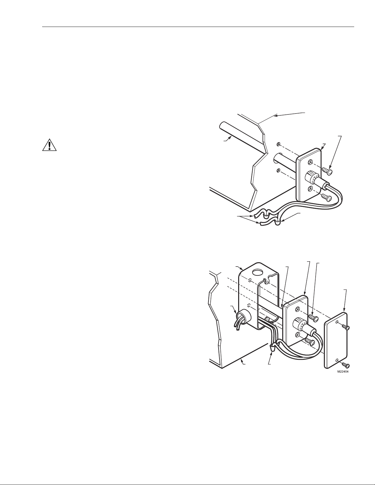
Fig. 2. Mounting C7046 Air Temperature
Sensor on a flat duct or plenum surface.
TANDARD UTILIT
IT B
PROB
FLAN
R
NO. 8 (4mm)
MOUNTING
SCREWS (NOT
ROVIDED
Mounting on a Flat Duct or Plenum Surface (Fig. 2)
1. Cut a 3/8 in. (9.5 mm) hole in the duct or plenum
surface at the desired location.
2. Insert sensor probe into the duct or plenum until the
flange rests against the duct or plenum wall.
3. If necessary, use the flange as a template to mark
and drill two holes for No. 8 mounting screws.
4. Fasten the sensor to the duct or plenum surface
with two No. 8 sheet metal screws (not provided).
Mounting in a Junction Box (Fig. 3)
1. Cut a 3/8 in. (9.5 mm) hole in the duct or plenum
surface at the desired location.
2. Remove the center rear knockout from the junction box
and insert the sensing probe through the knockout with
the flange flat against the outlet box.
NNECT
LOCKNUT
TO APPROPRIATE
TEM
NENT
TEM
DUCT OR
PLEN
NNECT SENSOR WIRE
WITH TWO WIRENUT
CONNECTORS
Fig. 3. Mounting C7046 Air Temperature
Sensor in a junction box.
FACEPLAT
OPTIONAL
NOT PROVIDED
3 60-2350—8
Page 4

C7046A,B,C,D AIR TEMPERATURE SENSORS
Wiring
CAUTION
Electrical Shock or Equipment Damage Hazard.
Can shock individuals or short equipment
circuitry.
Disconnect power supply before installation.
CAUTION
Erratic System Operation Hazard.
Failure to follow proper wiring practices can
introduce disruptive electrical interference (noise).
Keep wiring at least one foot away from large inductive
loads such as motors line starters, lighting ballasts,
and large power distribution panels.
Shielded cable is required in installations where these
guidelines cannot be met.
Ground shield only to grounded controller case.
IMPORTANT
1. All wiring must agree with applicable codes,
ordinances and regulations.
2. Do not mount sensor in incorrect environment.
3. Wire according to the applicable controller
instructions.
4. Erratic temperature readings from a sensor can be
caused by improper wiring practices. These must
be avoided to assure proper operation:
•Avoid poor wiring connections.
•Avoid intermittent or missing building earth ground.
•Do not mount sensor in incorrect environment.
W7081
LIMIT CONTROLLER
ECONOMIZER/MIXED AIR LOW LIMIT–A5
COLD DECK LOW LIMIT–A6
HOT DECK HIGH LIMIT–A7
12C7100B AVERAGING
TEMPERATURE SENSOR
MAY BE SUBSTITUTED IF
SPACE PERMITS.
REMOTE RETURN AIR SENSOR
USED WITH T7080B ONLY.
3456
21
21
3456
21
3456
(OR C7100B)
AIR SENSOR
50
55
60 NO JUMPER
45
55
55 NO JUMPER
90
110
130 NO JUMPER
24 Vdc
78
–+
+24 VDC
C7046B
REMOTE
RETURN
(IF USED)
2
T7080A,B
7
6
5
4
1
2
3
8
C7046B
(OR C7100B)
MIXED AIR
SENSOR
C7046B
(OR C7100B)
COLD DECK
SENSOR
C7046B
(OR C7100B)
HOT DECK
SENSOR
C7046B
(OR C7100B)
ZONE (N)
DISCHARGE
SENSOR
M17966
Connect low voltage wiring from the sensor to the appropriate
system component terminals using solderless connectors.
See Fig. 3.
NOTES:
1. For connections to the W973 Single Zone Logic
Panel, see Fig. 4.
2. For connections to the W7080 Multizone System,
see Fig. 5.
3. For connections to the Excel 500 Control System,
see Fig. 6.
4. For additional wiring information, refer to the
appropriate specification.
W973 LOGIC PANEL
SENSOR STAT 24 VAC ECONO
C7046A
1
POWER SUPPLY. PROVIDE DISCONNECT
MEANS AND OVERLOAD PROTECTION
AS REQUIRED.
C +20 H N
TT134251TRTRWBY
1
L1
L2
(HOT)
M17965
R
Fig. 4. Connecting C7046A Air Temperature
Sensor to a W973 Single Zone Logic Panel.
Fig. 5. Connecting C7046B Air Temperature Sensor
for mixed air, cold deck and hot deck sensing, zone
discharge and optional remote return air sensing
in W7080 Multizone System.
C7046D XF521A/XF526
1
1
2
2
AI 1
AI 2
AI 3
AI 4
AI 5
AI 6
AI 7
AI 8
1
2
3
4
5
6
7
8
9
10
11
12
13
14
15
16
17
18
M2825
Fig. 6. Connecting C7046D Air Temperature
Sensor to Excel 500 Control System.
60-2350—8 4
Page 5

OPERATION AND CHECKOUT
C7046A,B,C,D AIR TEMPERATURE SENSORS
Operation
The C7046A,B,C Air Temperature Sensors consist of a
thermistor sensing element mounted in a tubular probe. They
are applied at various locations throughout single zone and
multizone duct systems. The negative temperature coefficient
(NTC) characteristic of the thermistor element causes its
resistance to decrease as the sampled air temperature
increases. This resistance shift is balanced with other system
sensor signals by appropriate system logic panels to stabilize
system control.
The C7046D Air Temperature Sensor consists of a platinum
thin film sensor element mounted in a tubular probe. It can be
applied at various locations throughout single zone and
multizone duct systems. The positive temperature coefficient
(PTC) characteristics of the platinum thin film element causes
its resistance to increase as the sampled air temperature
increases. This resistance shift is balanced with other system
sensor signals by the Excel 500 Control System.
Checkout
Allow the C7046 Air Temperature Sensor to soak in the air
moving through the duct or plenum for a minimum of five
minutes before taking a resistance measurement.
1. Disconnect the sensor leadwires from the associated
system components.
2. Connect an ohmmeter across the leadwires.
3. Assure nominal resistance measurements are in
accordance with the resistance/temperature curves
shown in Figs. 7, 8 and 9.
4. Reconnect sensor leadwires to associated system
components.
5. Check operation of the complete control system.
120000
100000
80000
60000
40000
20000
0
RESISTANCE (OHMS)
20
30
-7 50 60
50 70 90
40
0 10 20 30 40
5 15 25
TEMPERATURE (DEGREES)
22,800 OHMS AT
77 F (25 C)
60 80 100
35
120
110
45 55
130
140
M17973
Fig. 8. C7046B Sensor resistance vs. temperature.
RESISTANCE
(OHMS)
1159
1141
1126
1111
1096
1081
1066
1051
60 65 70 75 80 85 90 95 100 105
55
1097 OHMS AT
77 F [25 C]
F
C
F
17000
16000
15000
14000
13000
12000
11000
10000
9000
8000
7000
6000
RESISTANCE (OHMS)
5000
4000
3000
2000
1000
605040 70
0-10
5
TEMPERATURE (DEGREES)
2010
15
3,000 OHMS
AT 77 F (25 C)
8010 20 30 90 100
30 35
25-5
F
C
M17969
Fig. 7. C7046A,C Sensor resistance vs. temperature.
13 15
20
25
TEMPERATURE (DEGREES)
30 35 38 41
M2826
Fig. 9. C7046D Sensor resistance vs. temperature.
C
5 60-2350—8
Page 6

60-2350—8 6
Page 7

7 60-2350—8
Page 8

By using this Honeywell literature, you agree that Honeywell will have no liability for any damages arising out of your use or modification to,
the literature. You will defend and indemnify Honeywell, its affiliates and subsidiaries, from and against any liability, cost, or damages,
including attorneys’ fees, arising out of, or resulting from, any modification to the literature by you.
Automation and Control Solutions
Honeywell International Inc. Honeywell Limited-Honeywell Limitée
Scarborough, Ontario
M1V 4Z9
60-2350—8 B.B. Rev. 7-04 www.honeywell.com
 Loading...