

Page 1
C7046A,B,C,D
)
D
)
A
(25)
3
)
)1 (25)
)
)
GASKET
R
)
USH
)
C
G
Air Temperature Sensors
INSTALLATION INSTRUCTIONS
APPLICATION
The C7046 series of Air Temperature Sensors function
as primary and/or secondary sensors in electronic control
systems.
INSTALLATION
When Installing this Product...
1. Read these instructions carefully. Failure to follow
them could damage the product or cause a hazardous condition.
2. Check the ratings given in the instructions and on
the product to make sure the product is suitable for
your application.
3. Installer must be a trained, experienced service
technician.
4. After installation is complete, check out product
operation as provided in these instructions.
CAUTION
Electrical Shock or Equipment Damage
Hazard.
Can shock individuals or short equipment
circuitry.
Disconnect power supply before installation.
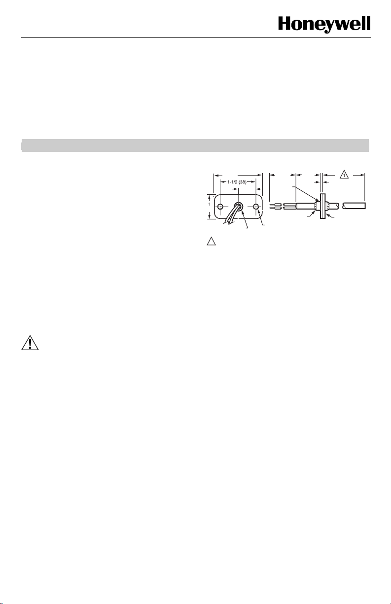
The sensor assembly (see Fig. 1) consists of an
aluminum sensor probe (element housed internally) with
attached flange that can be mounted on a flat duct or
plenum surface, or in a 2 in. by 4 in. (51 by 102 mm)
junction box using two No. 8 screws. Connections to the
sensor are made through two 6 in. (152 mm) leadwires.
2 (51
/4 (19
5/16 (9) DIAMETE
(BUSHING
INSERTION LENGTH DEPENDS UPON THE MODEL.
1
Fig. 1. C7046A,B,C,D Air Temperature
Sensor dimensions in in. (mm).
8 (203
PLASTI
BUSHIN
LOCKING P
NUTS (2
1/4 (6
IAMETER (2 HOLES
1/16 (2
NEOPRENE
M22402
NOTE: Sensor probe diameter is 1/4 in. (6 mm).
Location
The sensor should be located in the air duct or plenum
where it will sample an average air temperature. Avoid
locations where air stratification can cause sensing
errors.
Mounting
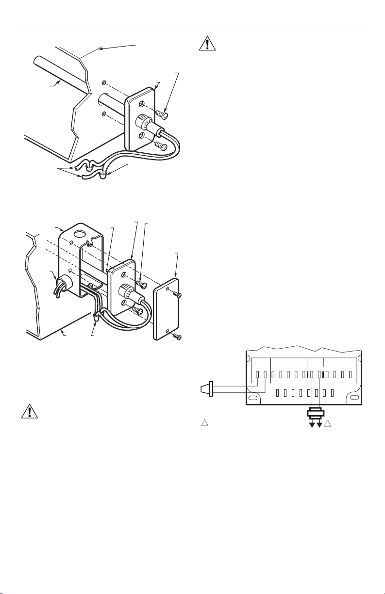
Mounting on Flat Duct or Plenum Surface (Fig. 2)
1. Cut a 3/8 in. (9.5 mm) hole in the duct or plenum
surface at the desired location.
2. Insert sensor probe into the duct or plenum until
the flange rests against the duct or plenum wall.
3. If necessary, use the flange as a template to mark
and drill two holes for No. 8 mounting screws.
4. Fasten the sensor to the duct or plenum surface
with two No. 8 sheet metal screws (not provided).
Mounting in a Junction Box (Fig. 3)
1. Cut a 3/8 in. (9.5 mm) hole in the duct or plenum
surface at the desired location.
2. Remove the center rear knockout from the junction
box and insert the sensing probe through the
knockout with the flange flat against the outlet box.
3. Using the flange as a template, mark and drill two
holes in the junction box and the duct or plenum
surface for No. 8 mounting screws.
4. Insert sensor probe through both the junction box
knockout and the 3/8 in. (9.5 mm) hole drilled in the
duct or plenum and fasten the junction box and
sensor to the duct or plenum surface.
® U.S. Registered Trademark
Copyright © 2004 Honeywell International Inc. • All Rights Reserved
62-0216
Page 2
C7046A,B,C,D AIR TEMPERATURE SENSORS
SENSO
OBE
GE
)
S
(
)
O
E
SYSTEM
COMPO
S
CO
O
S
(
)
A
SENSO
E
SYS
DUCT O
UM
GE
S
Y
CONDU
OX
CONNECTOR
CONDUIT
E
(
)
SYS
COMPO
S
CO
S
W
)
A
S
)
R
PR
T
APPROPRIAT
NENT
M22403
Fig. 2. Mounting C7046 Air Temperature
Sensor on a flat duct or plenum surface.
TANDARD UTILIT
IT B
LOCKNUT
TO APPROPRIATE
TEM
NENT
TEM
R
PLEN
Fig. 3. Mounting C7046 Air Temperature
Sensor in a junction box.
FLAN
R
PROB
NNECT SENSOR WIRE
ITH TWO WIRENUT
CONNECTORS (NOT PROVIDED
Wiring
CAUTION
Electrical Shock or Equipment Damage
Hazard.
Can shock individuals or short equipment
circuitry.
Disconnect power supply before installation.
SYSTEM DUCT
OR PLENUM
NO. 8 (4mm
MOUNTING SCREW
NOT PROVIDED
FLAN
NNECT SENSOR
WIRES WITH TW
WIRENUT CONNECTOR
NOT PROVIDED
NO. 8 (4 mm)
MOUNTING
CREWS (NOT
PROVIDED
FACEPLAT
OPTIONAL
M22404
CAUTION
Erratic System Operation Hazard.
Failure to follow proper wiring practices can
introduce disruptive electrical interference
(noise).
Keep wiring at least one foot away from large
inductive loads such as motors line starters,
lighting ballasts, and large power distribution
panels.
Shielded cable is required in installations where
these guidelines cannot be met.
Ground shield only to grounded controller case.
IMPORTANT
1. All wiring must agree with applicable codes,
ordinances and regulations.
2. Do not mount sensor in incorrect environment.
3. Wire according to the applicable controller
instructions.
4. Erratic temperature readings from a sensor can
be caused by improper wiring practices. These
must be avoided to assure proper operation:
•Avoid poor wiring connections.
•Avoid intermittent or missing building earth
ground.
•Do not mount sensor in incorrect environment.
Connect low voltage wiring from the sensor to the
appropriate system component terminals using
solderless connectors. See Fig. 3.
NOTES:
1. For connections to the W973 Single Zone
Logic Panel, see Fig. 4.
2. For connections to the W7080 Multizone
System, see Fig. 5.
3. For connections to the Excel 500 Control
System, see Fig. 6.
4. For additional wiring information, refer to the
appropriate specification.
W973 LOGIC PANEL
SENSOR STAT 24 VAC ECONO
C +20 H N
TT134251TRTRWBY
C7046A
1
POWER SUPPLY. PROVIDE DISCONNECT
MEANS AND OVERLOAD PROTECTION
AS REQUIRED.
Fig. 4. Connecting C7046A Air Temperature
Sensor to a W973 Single Zone Logic Panel.
1
L1
L2
(HOT)
R
M17965
62-0216 2
Page 3

A
W7081
LIMIT CONTROLLER
ECONOMIZER/MIXED AIR LOW LIMIT–A5
21
3456
50
55
COLD DECK LOW LIMIT–A6
21
HOT DECK HIGH LIMIT–A7
21
12C7100B AVERAGING
TEMPERATURE SENSOR
MAY BE SUBSTITUTED IF
SPACE PERMITS.
REMOTE RETURN AIR
SENSOR USED WITH T7080B ONLY.
Fig. 5. Connecting C7046B Air Temperature Sensor
for mixed air, cold deck and hot deck sensing, zone
discharge and optional remote return air sensing
in W7080 Multizone System.
C7046D XF521A/XF526
1
2
Fig. 6. Connecting C7046D Air Temperature
Sensor to Excel 500 Control System.
60 NO JUMPER
3456
45
55
55 NO JUMPER
3456
90
110
130 NO JUMPER
24 Vdc
78
–+
+24 VDC
C7046B
(OR C7100B)
REMOTE
RETURN
AIR SENSOR
(IF USED)
1
2
T7080A,B
7
6
5
4
2
1
AI 1
2
3
AI 2
4
5
AI 3
6
7
8
AI 4
9
10
AI 5
11
12
AI 6
13
14
AI 7
15
16
AI 8
17
18
1
2
3
8
(OR C7100B)
MIXED AIR
SENSOR
(OR C7100B)
COLD DECK
SENSOR
(OR C7100B)
HOT DECK
SENSOR
C7046B
(OR C7100B)
ZONE (N)
DISCHARGE
SENSOR
M2825
C7046B
C7046B
C7046B
M17966
C7046A,B,C,D AIR TEMPERATURE SENSORS
OPERATION AND CHECKOUT
Operation
The C7046A,B,C Air Temperature Sensors consist of a
thermistor sensing element mounted in a tubular probe.
They are applied at various locations throughout single
zone and multizone duct systems. The negative
temperature coefficient (NTC) characteristic of the
thermistor element causes its resistance to decrease as
the sampled air temperature increases. This resistance
shift is balanced with other system sensor signals by
appropriate system logic panels to stabilize system
control.
The C7046D Air Temperature Sensor consists of a
platinum thin film sensor element mounted in a tubular
probe. It can be applied at various locations throughout
single zone and multizone duct systems. The positive
temperature coefficient (PTC) characteristics of the
platinum thin film element causes its resistance to
increase as the sampled air temperature increases. This
resistance shift is balanced with other system sensor
signals by the Excel 500 Control System.
Checkout
Allow the C7046 Air Temperature Sensor to soak in the
air moving through the duct or plenum for a minimum of
five minutes before taking a resistance measurement.
1. Disconnect the sensor leadwires from the associated system components.
2. Connect an ohmmeter across the leadwires.
3. Assure nominal resistance measurements are in
accordance with the resistance/temperatu re curves
shown in Figs. 7, 8 and 9.
4. Reconnect sensor leadwires to associated system
components.
5. Check operation of the complete control system.
17000
16000
15000
14000
13000
12000
11000
10000
9000
8000
7000
6000
RESISTANCE (OHMS)
5000
4000
3000
2000
1000
0-10
TEMPERATURE (DEGREES)
605040 70
5
15
Fig. 7. C7046A,C Sensor resistance vs. temperature.
2010
3,000 OHMS
AT 77 F (25 C)
8010 20 30 90 100
30 35
25-5
M17969
F
C
3 62-0216
Page 4

C7046A,B,C,D AIR TEMPERATURE SENSORS
120000
100000
80000
60000
40000
20000
0
RESISTANCE (OHMS)
20
-7 50 60
50 70 90
30
40
0 10 20 30 40
5 15 25
22,800 OHMS AT
77 F (25 C)
60 80 100
TEMPERATURE (DEGREES)
35
110
120
45 55
130
M17973
Fig. 8. C7046B Sensor resistance vs. temperature.
RESISTANCE
(OHMS)
1159
1141
1126
F
140
C
1111
1096
1081
1066
1051
60 65 70 75 80 85 90 95 100 105
55
13 15
20
TEMPERATURE (DEGREES)
1097 OHMS AT
77 F [25 C]
25
30 35 38 41
M2826
F
C
Fig. 9. C7046D Sensor resistance vs. temperature.
Automation and Control Solutions
Honeywell International Inc. Honeywell Limited-Honeywell Limitée
1985 Douglas Drive North 35 Dynamic Drive
Golden Valley, MN 55422 Scarborough, Ontario
M1V 4Z9
62-0216 B.B. 11-04 www.honeywell.com
 Loading...