

Page 1
Introductory text may go here. Lorem ipsum dolor sit amet, consectetuer
70-2321-06
adipiscing elit, sed diam nonummy nibh euismod tincidunt ut laoreet dolore
magna aliquam erat volutpat. U adipiscing elit, sed diam nonummy nibh euismod
tincidunt ut laoreet dolore magna aliquam erat volutpat. Ut wisi enim ad minim
Zoning System Design Manual
veniam, quis nostrud exerci tation ullamcorper suscipit lobortis nisl ut aliquip ex
ea commodo consequat t wisi enim ad minim veniam, quis nostrud exerci tation
Zoning Made Effortless
ullamcorper suscipit lobortis nisl ut aliquip ex ea commodo consequat.
Page 2
Zoning System Design Manual
TYPICAL HOME
:
:
IDEAL HOME - WITH RESIDEO ZONING
INTRODUCTION
The Concept of Zoning
The basic principle of forced air zoning is to allow one HVAC system to be controlled by multiple thermostats, heating and cooling a building in zones rather than as a whole. This makes homes and businesses more comfortable.
When combined with setback thermostats, zone setback is possible, resulting in significant energy savings. Forced
air zoning makes a common HVAC system more efficient by concentrating the unit’s capacity where and when you
need it instead of pouring air throughout the building regardless of the temperature in the individual rooms.
According to a 2010 American Home Comfort Study, 68% of US homeowners are uncomfortable in their homes at
certain times of the year. Zoning solves this problem.
To accomplish this we utilize:
Zoning PanelReceives requests from thermostats and coordinates the HVAC system and damper positions.
ThermostatsRequests conditioned air only in zones where required.
Duct DampersDirects air to rooms (zones) only when called for by a room thermostat.
A Pressure Relief DamperEfficiently controls excess supply air as dampers open and close.
Discharge Air Temperature Sensor (DATS)Avoids freeze-up and tripping on high limit by sensing the supply
duct temperature. The zone panel cycles off the equipment when DATS limits are exceeded. The equipment is
turned back on automatically.
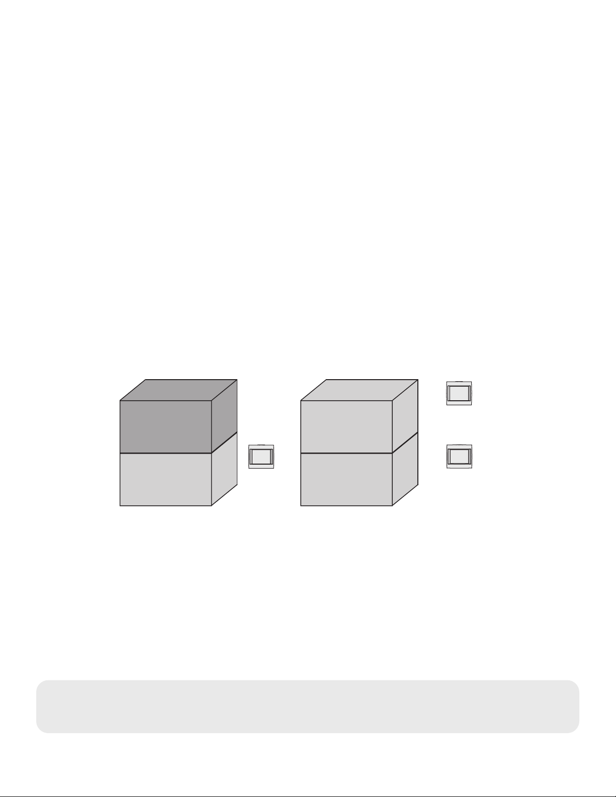
Fig. 1 depicts typical home temperatures compared to those of a home with Resideo zoning.
SECOND FLOOR
(SLEEPING AREA)
ROOM TEMPERATURE
76-80°F
25-27°C
FIRST FLOOR
(LIVING AREA)
ROOM TEMPERATURE
72°F
22°C
THERMOSTAT
SETPOINT:
72°F/22°C
ZONE 1
(SLEEPING AREA)
ROOM TEMPERATURE
72°F
22°C
ZONE 2
(LIVING AREA)
ROOM TEMPERATURE
72°F
22°C
THERMOSTAT SETPOINT
72°F/22°C
THERMOSTAT SETPOINT
72°F/22°C
M28112A
Fig. 1. Typical home (no zoning) compared to ideal home with Resideo zoning.
Need Help?
For assistance please visit customer.resideo.com
or call the Zoning Hotline toll-free at 18008288367
70-2321—06 2
Page 3

Zoning System Design Manual
INTRODUCTION
Fig. 2 depicts a typical residential layout with three zones. Zoning provides two key benefits:
• Customer Comfort: heating and cooling where you want it, when you want it.
• Energy Savings: heat and cool only zones that are occupied.
In the following pages you will learn how to apply the principles of forced air zoning in new and existing projects,
creating a more comfortable indoor environment.
FAMILY
ROOM
KITCHEN
ROUND ZONE DAMPER
DIFFUSER
LIVING
ROOM
DINING
ROOM
HVAC EQUIPMENTZONE THERMOSTAT
ENTRY BEDROOM
1
BATH
BATH
BEDROOM
2
MASTER
SUITE
M28051A
Fig. 2. Typical residential layout with multiple zones on one HVAC system.
3 70-2321—06
Page 4
Zoning System Design Manual
M28111
PLAN THE ZONES
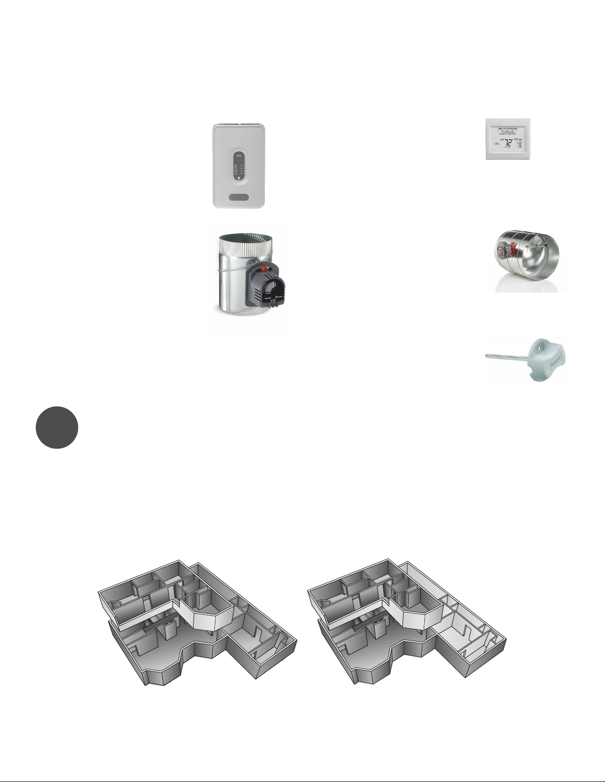
In planning a zone system, here's what you need:
Panel
• To Operate Dampers and
Equipment
• Transformer to power panel
Dampers
• Controls circulating air in
heating/cooling systems
• Round or rectangular
configuration
• Normally open/power closed
actuator included
Thermostats
• Programmable or
Non Programmable
Pressure Relief Dampers:
• Provides static pressure buildup
relief
• Actuator included
• No wiring necessary
Discharge Air Temperature Sensor
(DATS) :
• Sensor which protects HVAC
equipment
1
Divide the Home Into Zones
There are a number of ways to divide a house into zones: by floor, in groups of rooms adjacent to each
other, rooms grouped by compass orientation—here is a typical setup:
Zone 1: areas primarily used at night (bedrooms)
Zone 2: areas primarily used during the day (living room, kitchen)
Zone 3: a third space that would benefit from its own HVAC control, such as a master bedroom suite,
a basement, living space above a garage, a home office, etc.
A good rule of thumb is to make no zone smaller than about 25% of total system capacity, measured in
cubic feet/minute (CFM).
Zone 2: Night-time
Zone 2: Night-time
Zone 1: Daytime
Zone 1: Daytime
Zone 2: Night-time
Zone 2: Night-time
Zone 1: Daytime
Zone 1: Daytime
Zone 3:
Zone 3:
Home
Home
office
office
Fig. 3. Typical residential layout with multiple zones on one HVAC system.
70-2321—06 4
Page 5
2
Zoning System Design Manual
DUCTS AND DAMPERS
Size the Ductwork
In New Construction: ductwork is sized as usual for the size of the home; trunks are sized for the
amount of air going to the zone.
Ductwork should be designed normally, typically .10 or .08 in. w.c./100 ft.
Proper duct design of a zoned system will:
• Maintain proper airflow through the HVAC unit when only one zone is open.
• And maintain proper airflow to all zones when all are open.
In Retrofit Applications: zones are somewhat limited by how the ducts were originally constructed, but
any home can be zoned provided there is access to the ductwork. See page 10 for zoning information
specific to retrofit applications.
3
Select Dampers
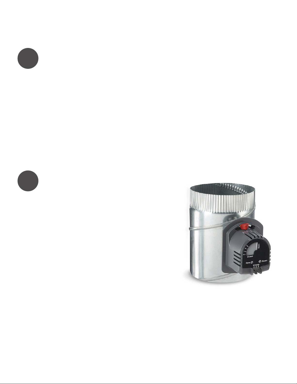
Use ZD dampers for rectangular ducts. Use ARD or RRD
dampers for round ducts in residential systems up to
2000 CFM.
For systems over 2000 CFM or commercial systems,
see page 11.
Install the Dampers
A supply air damper should not be placed closer than 6
ft. to a diffuser. The damper should also be at least 3 ft.
away from the plenum. (Less than 6 ft. between damper
and diffuser could create objectionable air noise in the
conditioned space and 3 ft. of duct off the plenum will
reduce turbulence.) These minimums are recommendations for optimal performance; however, each installation presents its own challenges, so each installation
will vary. For instance, in some installations the damper
may need to be mounted directly on the plenum.
Allow for Access
Dampers should be installed in a location that can be
accessed for service. If a damper needs to be "buried,"
place a decorative register over it to provide access.
Balancing Dampers
Balancing dampers should be included in the duct work, because a zoned home needs to be balanced
just as a non-zoned home does.
5 70-2321—06
Page 6
Zoning System Design Manual
PRESSURE RELIEF DAMPERS AND DATS
Size the Pressure Relief Damper
4
return duct.
Supply duct systems should be sized to handle the total airflow
when all zones are open, and use a CPRD bypass capable of
handling the excess air when only the smallest zone is calling.
Excess air should be bypassed into the return air duct.
Determine the size of the bypass as follows:
For example, on a 4-ton system ....................................... 1600 CFM System
with the smallest zone designed to handle ................ - 400 CFM Smallest Zone
the bypass must be able to handle ................................. = 1200 CFM of airflow in bypass
When few zones are calling, static pressure in the system increases, and air is bypassed from supply to return. This
ensures that the throw of air at the register is correct whether one zone is calling or all zones are calling.
This method of duct design is also a great way to control excess humidity in the home, especially in southern climates. Bypassing air from the supply duct into the return duct accelerates the dehumidification ability of the equipment, creating greater comfort for the homeowner.
Install between supply and return.
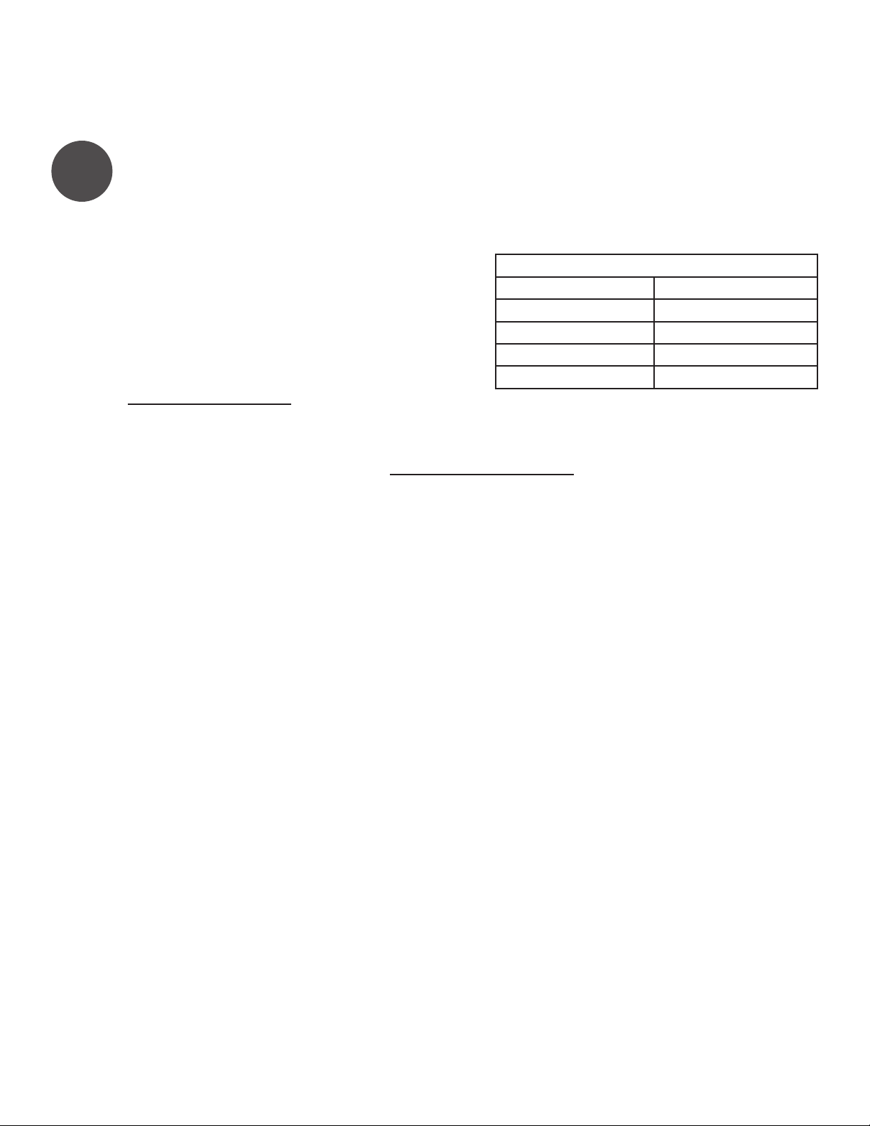
All zoning systems should be installed with a supply-to-return pressure relief damper. A Constant
Pressure Regulating Damper (CPRD) is used to bypass excess airflow from the supply duct into the
Table 1. CPRD Sizes.
Round CPRD
Model Number Bypass
CPRD8 600 CFM
CPRD10 1000 CFM
CPRD12 1400 CFM
CFM System
- CFM Smallest Zone
= CFM Bypass
CPRD14 1700 CFM
Use duct collars (not supplied) when connecting
a CPRD round bypass to rectangular ducting.
Alternative Pressure Relief Methods
If pressure relief dampers are not allowed in your state/region, or if the space is too confined to install a bypass
back to the return, use one of the below methods for reliving the pressure-
1 If the system has 23 zones that are similar in size, you may be able to get by without any pressure relief damper.
If the equipment has a high-speed/low-speed fan terminal (typically labeled DS, BK, ODD, DHUM, or DEHUM)
wire this to the DS/BK on the zone panel. This lowers fan speed when a single zone is calling for cooling (or heat
with heat pump systems). Then test each zone individually to verify pressure is not too high.
2 If there is no space for bypass ductwork, the zone dampers can be set to allow some air to leak. By setting the
larger zone dampers to a minimum position, excess air pressure can be relieved even when only one zone is calling. Minimal leakage to zones that are not calling for heat or cooling does not typically cause noticeable temperature swings, but the homeowner should be advised that air will be coming from these registers even when
that zone is not calling.
3 Instead of running the pressure relief damper from the supply to the return ducting, you might be able to run the
duct from supply to a “alternate pressure relief area” in some houses. This would be an area of the house in which
overheating or cooling o the space is not a concern; for example a hallway, false ceiling, or basement.
70-2321—06 6
Page 7
M36666
PRESSURE RELIEF DAMPERS AND DATS
M34210
Setting the Regulator
The CPRD is factory set to open at approximately .5"WC." This setting is
satisfactory for most installations. Some
systems have higher static pressure. Test this by:
1 Make all zones call fan, heat, or cool; whichever has the highest CFM.
2 Verify that the damper position indicator points to closed.
3 If it does not point to closed:
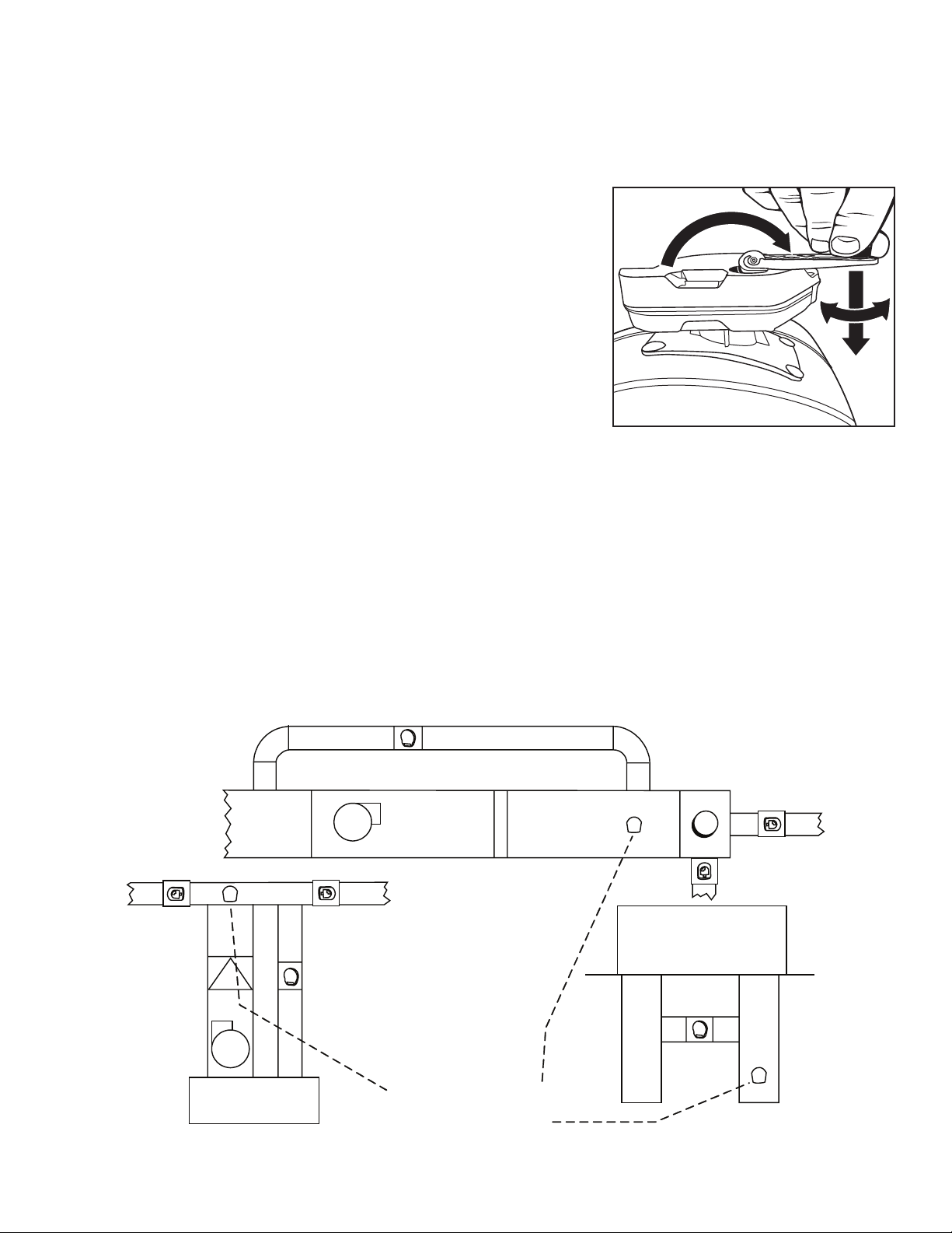
• Flip the adjustment crank out (see Fig. 4)
• Push down on the adjustment crank with gentle pressure. Caution:
Do not rotate the adjustment crank without first pushing it down
• Turn the adjustment crank clockwise until the indicator points to
closed
• When done, flip the adjustment crank back into the locked position
4 Make only the smallest zone call for fan, heat, or cool.
5 Verify that the airflow into that zone is not objectionable. If it is, then set
the regulator to a lower pressure.
Zoning System Design Manual
Fig. 4. Adjustment crank.
Discharge Air Temperature Sensor (DATS)
The DATS should be located in the supply trunk between the evaporator coil or heat exchanger and the first zone
damper. If this is not possible, it is permissible to mount the DATS in the bypass duct. It is recommended to set the
high limit approximately 15°F below the furnace high limit. Some modern furnaces have low high limit settings, so
make sure the correct zone panel is selected for the equipment.
The HZ221 zone panel is for heat pumps only and has a fixed high limit (120°F for heat pump and 160°F for aux
heat) and low limit (45°F).
The HZ311 has a fixed high limit (160°F) and low limit (45°F).
The HZ322 and HZ432 zone panels have adjustable high limit (110°F180°F ) and low limit (30°F60°F).
Note: It is often advisable to install the DATS in the bypass duct rather than supply duct for heat pumps with elec-
tric auxiliary heat.
HORIZONTAL
THE DATS MUST BE LOCATED SO THAT IT CAN
PROPERLY SENSE THE LEAVING AIR
TEMPERATURE.
NOTE: MOUNTING THE DATS TOO CLOSE TO THE
HEAT EXCHANGER OR EVAPORATOR COIL WILL
CAUSE EXCESSIVE CYCLING OF THE SYSTEM AND
RESULT IN DISCOMFORT FOR THE BUILDING
OCCUPANTS.
ROOF TOP EQUIPMENT
UP-FLOW
DISCHARGE AIR
TEMPERATURE SENSOR (DATS)
Fig. 5. DATS mounting locations.
7 70-2321—06
Page 8
Zoning System Design Manual
ZONE PANEL
Install the Panel
5
Mount on return, stud, wall, or roof truss.
Zone Panels should not be exposed to weather or installed in a location where they might get wet. Like a
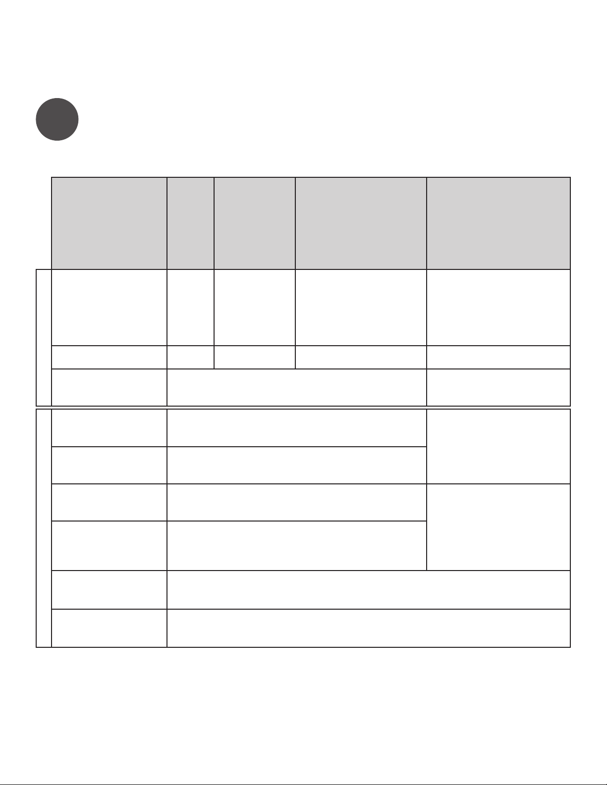
damper, they must be accessible for service, if required. Select a zone control panel kit using Table 2.
Table 2. Conventional Zone Panel Selection Guide.
APPLICATION CONVEN
TIONAL
1HEAT/
1COOL
2 ZONES. WIRED
HZ311K
THERMOSTATS
3 ZONES. WIRED
HZ311K HZ322K
THERMOSTATS.
432 ZONES
WIRED THERMOSTATS
23 zones WIRELESS ZONING
WITH TH6320R or TH5320R
RedLINK WIRELESS
THERMOSTATS
4 zones WIRELESS ZONING
WITH TH6320R or TH5320R
RedLINK WIRELESS
THERMOSTATS
23 zones WIRELESS ZONING
With TH8110R, TH8320R, or
TH8321R RedLINK WIRELESS
THERMOSTATS
4 zones WIRELESS ZONING
With TH8110R, TH8320R, or
TH8321R RedLINK WIRELESS
THERMOSTATS
WIRELESS THERMOSTATS
532 zones WIRELESS
ZONING WITH TH6320R or
TH5320R RedLINK WIRELESS
THERMOSTATS
532 zones WIRELESS ZONING
With TH8110R, TH8320R, or
TH8321R RedLINK WIRELESS
THERMOSTATS
HZ432K for the first 4 zones. Add a TAZ4 + separate transformer for each
additional 4 zones
HZ322K + THM4000R adaptor HZ432K + THM4000R adaptor
HZ432K + THM4000R adaptor
HZ322K + THM4000R* adaptor.
(Cannot do remote scheduling when THM4000R and THM6000R gateway are
used. TH8321R loses IAQ control when used with THM4000R)
HZ432K + THM4000R* adaptor.
(Cannot do remote scheduling when THM4000R and THM6000R gateway are
used. TH8321R loses IAQ control when used with THM4000R)
HZ432K for the first 4 zones. Add a TAZ4 + separate transformer for each additional 4 zones. THM4000 CANNOT be
used for
systems with over 5 zones. A separate THM5320R EIM is needed for each TH5320R or TH6320R wireless thermostat.
(C7089U1006 wired outdoor sensor needed for dual fuel)
HZ432K for the first 4 zones. Add a TAZ4 + separate transformer for each additional 4 zones. THM4000 CANNOT be
used for
systems with over 5 zones. A separate THM5421R1021 EIM is needed for each TH8110R, TH8320R, or TH8321R wireless
thermostat. EIMs should be spaced at least 2 feet apart. (C7089U1006 wired outdoor sensor needed for dual fuel)
* For full functionality of TH8110R , TH8320R, and TH8321R thermostats, use a separate THM5421R1021 EIM for each thermostat rather
than a single THM4 000R. The EIMs should be spaced a least 2 feet apart and wired to the zone connections of HZ322 or HZ432 that the
thermostat controls. With THM400 0R, the lost functionality is:
1 Cannot link to remote indoor sensor.
2 Cannot do remote scheduling or humidity control through app when THM6 000R gateway is used for Internet access.
3 Loss of IAQ control for TH8321R(humidifier, dehumidifier, or ventilator). TH8110R and TH8320R don't control IAQ either way.
HEAT PUMP WITH
SINGLE STAGE
COMPRESSOR
AND ELECTRIC
AUXILIARY HEAT
STAGE.
HZ221K (Heatpump
thermostats with
O wire only. For
conventional
thermostats
or heatpump
thermostats with
B changeover, use
HZ322K.
• GAS FURNACE WITH 2
HEAT STAGES AND 2 COOL
STAGES.
• HEATPUMP WITH 2
COMPRESSOR STAGES AND
NO AUXILIARY HEAT.
• HEATPUMP WITH 1
COMPRESSOR STAGE +
AUXILIARY HEAT.
• HYDROAIR HEAT.
HZ322K
• HEATPUMP WITH 2
COMPRESSOR STAGES +
AUXILIARY HEAT.
• DUAL FUEL HEATPUMP WITH
12 COMPRESSOR STAGES + 12
FURNACE STAGES.
• 3 CONVENTIONAL HEAT STAGES
+ 12 COOL STAGES
HZ432K (C7089U1006 wired outdoor
sensor needed for dual fuel)
HZ432K (C7089U1006 wired outdoor
sensor needed for dual fuel)
HZ432K for the first 4 zones. Add a
TAZ4 + separate transformer for each
additional 4 zones, (C7089U1006 wired
outdoor sensor needed for dual fuel)
(C7089R1013 wireless outdoor sensor
needed for dual fuel)
HZ432K + THM4000R adaptor.
(TH8110R, TH8320R, and TH8320R
models can do remote scheduling when
wired to the panel. These models cannot
do remote scheduling when THM4000R
and THM6000R gateway are used.
TH8321R loses IAQ control when used
with THM4000R).
(C7089R1013 wireless outdoor sensor
needed for dual fuel)
70-2321—06 8
Page 9
Zoning System Design Manual
COMPRESSO
M36667
TrueZONE PANEL MOUNTED
ON RETURN DUCT
RETURN DUCT
DAMPERS
ZONE PANEL
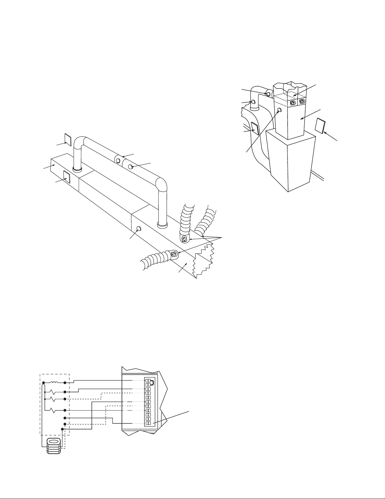
The zone panel is typically installed near the indoor unit, in a garage, crawl space, basement, or attic. Zone panels
are often installed on the return air duct. However, in some heat pump applications, the homeowner or building
occupant may require access to the panel to change
into the emergency heat mode. To meet these needs,
install the panel in a utility closet or other convenient
area where the panel is easily accessed.
TrueZONE PANEL
MOUNTED ON WALL
TrueZONE PANEL
MOUNTED ON
RETURN DUCT
CPRD PRESSURE
RELIEF DAMPER
DATS
(ALTERNATE LOCATION)
CPRD PRESSURE
RELIEF DAMPER
(ALTERNATE LOCATION)
DATS (AT LEAST 3 FT)
DATS
FROM PLENUM
FURNACE OR AIR HANDLER
ZD SERIES
ZONE DAMPERS
SUPPLY DUCT
TrueZONE PANEL
MOUNTED ON WALL
Fig. 7. Typical horizontal
Transformer
Mount and wire a dedicated transformer to the zone panel. The AT140A1042 is rated to 130°F (54°C). If it is to be
mounted in an attic that may get much hotter, install the AT175A1008, which is rated to provide 50 VA at 165°F
(74°C). Connect power to the zone control panel after all other wires are attached.
Variable Speed Fan
A variable speed fan or ECM blower changes blower speed to deliver a constant CFM regardless of static pressure.
To use zoning with a variable speed fan, plan and install zoning normally, and use a CPRD or MARD (round) damper
with static pressure control (SPC) for bypass.
24 VOLT TRANS.
C
FAN RELAY
HVAC system.
HVAC
R
W
W2
G
BK
Y2
Y
Fig. 8. Wiring variable speed
R
RELAY
DATS (AT LEAST 3 FEET
FROM PLENUM)
RH
RC
W1/E
W2
W3
Y1
Y2
G
EQUIPMENT
O
B
K
DS/B
M28169
fan to TrueZONE panel.
SUPPLY
DUCT
Fig. 6. Typical upflow HVAC system.
ARD
Thermostats
Install thermostats using instructions
provided with thermostat. Wireless
thermostats can be used to speed
M36668
installation.
If using a Resideo TrueZONE panel, the panel's DS/
BK terminal is intended for use with a variable-speed
fan. When one zone is calling (or less than 25% of
capacity on systems with more than 4 zones), this
terminal will be de-energized of 24 VAC. This reduces blower speed on most variable speed blowers.
9 70-2321—06
Page 10
Zoning System Design Manual
M28119
RETROFIT APPLICATIONS
For retrofit applications, first you have to ensure that the duct system is adequate for room/zone loads, and that the
existing HVAC system is properly sized to deliver heat/cool. After that, planning the zone system is very similar to
new construction.
Rigid Duct, Rectangular Sheet Metal Duct, Knockdown (KD) Duct
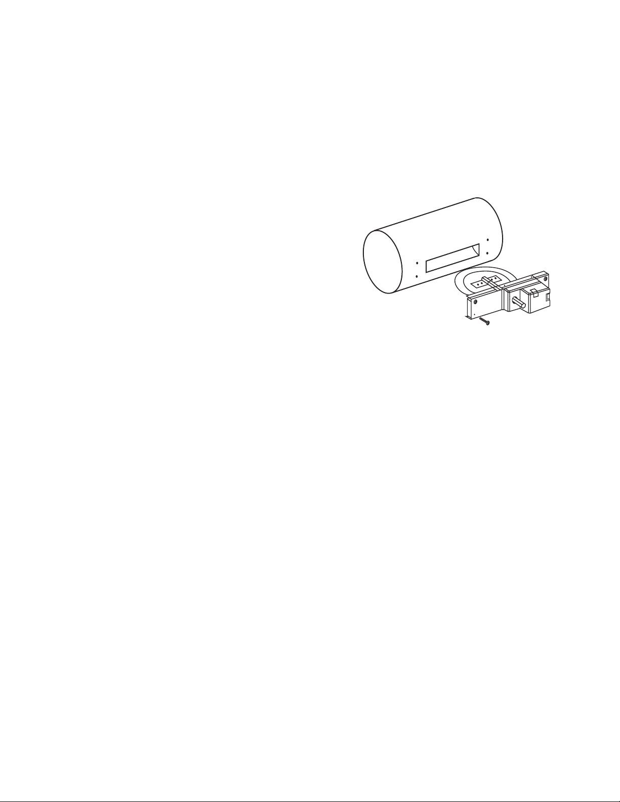
Using a retrofit round damper (RRD) significantly reduces labor—
it installs in a fraction of the time—and overall system installation cost. A retrofit damper slides into rigid round pipe for quick
installation.
The RRD dampers are available in 5, 6, 7, and 8-in. diameters.
Multiple RRD dampers may be wired in parallel.
Fig. 9. Installing retrofit round damper.
Flex Duct
For retrofit applications in flex duct, use round ARD dampers. The round ARD is a galvanized steel single blade
damper with a low-leakage gasket, and comes in a range of sizes from 520 in. Up to 4 ARD dampers can be wired
in parallel to a zone as long as the transformer has sufficient VA. Use an SDCR isolation relay for zones with more
than 4 ARD dampers.
Thermostats
The existing thermostat can often be used for one zone, but as it might be difficult to run wires to the other zones,
RedLink wireless thermostats can be used.
70-2321—06 10
Page 11

Zoning System Design Manual
COMMERCIAL ZONING
Zoning for commercial buildings makes just as much sense as zoning for residential buildings: in a large office
building, each office suite could have its own zone, giving each occupant the ability to set the heat/cool to his or
her comfort.
Zone Design
While a typical residential building might have a system of 5 tons or less, commercial buildings typically have much
larger (up to 20 ton) HVAC units. A commercial zoning system will likely have more zones, and the ducts might be
bigger, but the basic principles of design and the devices used to implement zoning remain the same.
Pressure Relief Damper
The pressure relief damper may be a motorized damper such as the MARD, controlled by a static pressure control.
The MARD is then wired to a static pressure control (SPC) to modulate the bypass air.
Zone Damper
Zone dampers must be able to handle the higher airflow and static pressure of a larger HVAC system. Use a MARD
or RRD for round ducts. Honey well Home doesn’t offer commercial-rated rectangular dampers. Commercial dampers made by other companies can be used if they are powered by 24 volts AC. These could be either spring-open/
power-closed, or power-open/power-closed models. The zone panel sends a constant voltage to either open or
closed, so verify the damper used is compatible with constant voltage.
11 70-2321—06
Page 12
CHECK EQUIPMENT FOR CORRECT OPERATION
M28194
HZ221 or HZ311 panels
Call for heat or cool from each zone individually. Verify the equipment comes on and dampers go to correct position. Verify CPRD relief damper is adjusted correctly (see "Setting the Regulator" on page 7).
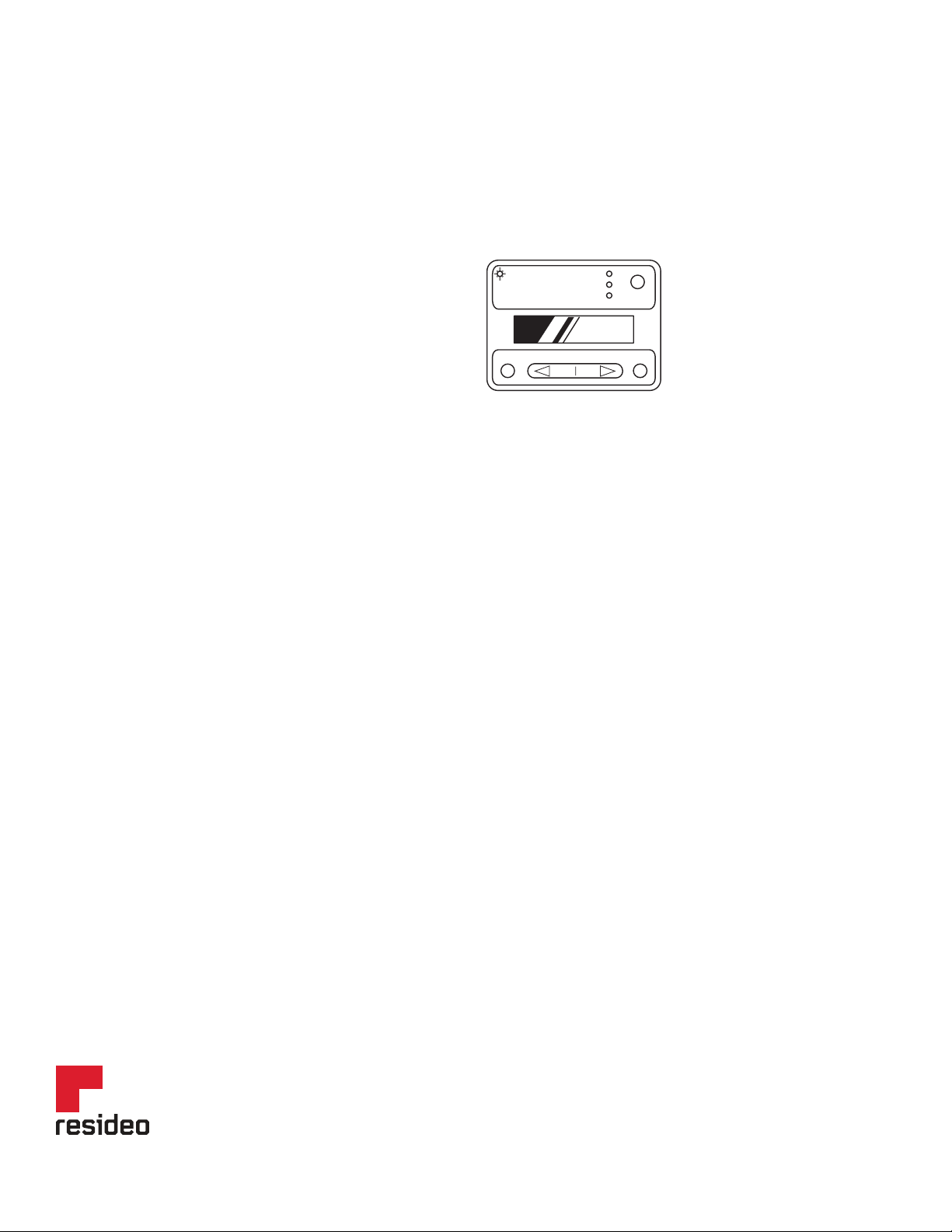
HZ322 or HZ432 panels
From the home mode, press mode button twice to enter
checkout mode on zone panel. In checkout mode you
WIRELESS
can:
1 Test every heat stage.
2 Test every cool stage.
3 Test emergency heat operation (if zone panel is con-
BACK NEXT
figured for a heat pump with aux heat).
4 Open and close each zone damper.
After checkout mode you should make a call for heat or cool from each thermostat to verify correct communication
to the zone panel. Also, verify CPRD relief damper is adjusted correctly (see "Setting the Regulator" on page 7).
HOME
CONFIG
CHECK OUT
ADJUST SETTING
MODE
Resideo Technologies, Inc.
1985 Douglas Drive North, Golden Valley, MN 55422
www.resideo.com
© 2020 Resideo Technologies, Inc. All rights reserved.
The Honeywell Home trademark is used under license from Honeywell International, Inc. This product is manufactured by Resideo Technologies, Inc. and its affiliates.
1-800-633-3991
70-2321—06 M.S. Rev. 03-20 | Printed in United States
 Loading...