

Page 1

Voice Evacuation Control Panels
AUDIO•COMMAND•CENTER•25/50
AUDIO•COMMAND•CENTER•25/50ZS
AUDIO•COMMAND•CENTER•25/50ZST
Instruction Manual
Document 51889
6/8/2010 Rev:
P/N 51889:E1 ECN 10-278
E1
Page 2

Fire Alarm System Limitations
While a fire alarm system may lower insurance rates, it is not a substitute for fire insurance!
An automatic fire alarm system—typically made up of
smoke detectors, heat detectors, manual pull stations, audible
warning devices, and a fire alarm control panel with remote
notification capability—can provide early warning of a developing fire. Such a system, however, does not assure protection
against property damage or loss of life resulting from a fire.
The Manufacturer recommends that smoke and/or heat detectors be located throughout a protected premise following the
recommendations of the National Fire Protection Association
Standard 72 (NFPA 72), manufacturer's recommendations,
State and local codes, and the recommendations contained in
the Guides for Proper Use of System Smoke Detectors, which
are made available at no charge to all installing dealers.
These documents can be found at http://www.systemsensor.com/html/applicat.html. A study by the Federal Emergency Management Agency (an agency of the United States
government) indicated that smoke detectors may not go off in
as many as 35% of all fires. While fire alarm systems are
designed to provide early warning against fire, they do not
guarantee warning or protection against fire. A fire alarm system may not provide timely or adequate warning, or simply
may not function, for a variety of reasons:
Smoke detectors may not sense fire where smoke cannot
reach the detectors such as in chimneys, in or behind walls, on
roofs, or on the other side of closed doors. Smoke detectors
also may not sense a fire on another level or floor of a building.
A second-floor detector, for example, may not sense a firstfloor or basement fire.
Particles of combustion or “smoke” from a developing fire
may not reach the sensing chambers of smoke detectors
because:
• Barriers such as closed or partially closed doors, walls, or
chimneys may inhibit particle or smoke flow.
• Smoke particles may become “cold,” stratify, and not reach
the ceiling or upper walls where detectors are located.
• Smoke particles may be blown away from detectors by air
outlets.
• Smoke particles may be drawn into air returns before
reaching the detector.
The amount of “smoke” present may be insufficient to alarm
smoke detectors. Smoke detectors are designed to alarm at
various levels of smoke density. If such density levels are not
created by a developing fire at the location of detectors, the
detectors will not go into alarm.
Smoke detectors, even when working properly, have sensing
limitations. Detectors that have photoelectronic sensing
chambers tend to detect smoldering fires better than flaming
fires, which have little visible smoke. Detectors that have ionizing-type sensing chambers tend to detect fast-flaming fires
better than smoldering fires. Because fires develop in different
ways and are often unpredictable in their growth, neither type
of detector is necessarily best and a given type of detector
may not provide adequate warning of a fire.
Smoke detectors cannot be expected to provide adequate
warning of fires caused by arson, children playing with
matches (especially in bedrooms), smoking in bed, and violent
explosions (caused by escaping gas, improper storage of
flammable materials, etc.).
Heat detectors do not sense particles of combustion and
alarm only when heat on their sensors increases at a predetermined rate or reaches a predetermined level. Rate-of-rise
heat detectors may be subject to reduced sensitivity over time.
For this reason, the rate-of-rise feature of each detector
should be tested at least once per year by a qualified fire protection specialist. Heat detectors are designed to protect
property, not life.
IMPORTANT! Smoke detectors must be installed in the
same room as the control panel and in rooms used by the system for the connection of alarm transmission wiring, communications, signaling, and/or power. If detectors are not so
located, a developing fire may damage the alarm system, crippling its ability to report a fire.
Audible warning devices such as bells may not alert people
if these devices are located on the other side of closed or
partly open doors or are located on another floor of a building.
Any warning device may fail to alert people with a disability or
those who have recently consumed drugs, alcohol or medication. Please note that:
• Strobes can, under certain circumstances, cause seizures
in people with conditions such as epilepsy.
• Studies have shown that certain people, even when they
hear a fire alarm signal, do not respond or comprehend the
meaning of the signal. It is the property owner's responsibility to conduct fire drills and other training exercise to
make people aware of fire alarm signals and instruct them
on the proper reaction to alarm signals.
• In rare instances, the sounding of a warning device can
cause temporary or permanent hearing loss.
A fire alarm system will not operate without any electrical
power. If AC power fails, the system will operate from standby
batteries only for a specified time and only if the batteries have
been properly maintained and replaced regularly.
Equipment used in the system may not be technically compatible with the control panel. It is essential to use only equipment listed for service with your control panel.
Telephone lines needed to transmit alarm signals from a
premise to a central monitoring station may be out of service
or temporarily disabled. For added protection against telephone line failure, backup radio transmission systems are recommended.
The most common cause of fire alarm malfunction is inadequate maintenance. To keep the entire fire alarm system in
excellent working order, ongoing maintenance is required per
the manufacturer's recommendations, and UL and NFPA standards. At a minimum, the requirements of NFPA 72 shall be
followed. Environments with large amounts of dust, dirt or
high air velocity require more frequent maintenance. A maintenance agreement should be arranged through the local manufacturer's representative. Maintenance should be scheduled
monthly or as required by National and/or local fire codes and
should be performed by authorized professional fire alarm
installers only. Adequate written records of all inspections
should be kept.
Limit-C1-2-2007
2 Audio Command Center Series Manual — P/N 51889:E1 6/8/2010
Page 3

Installation Precautions
Adherence to the following will aid in problem-free installation with long-term reliability:
WARNING - Several different sources of power can be
connected to the fire alarm control panel. Disconnect all
sources of power before servicing. Control unit and associated equipment may be damaged by removing and/or inserting cards, modules, or interconnecting cables while the unit is
energized. Do not attempt to install, service, or operate this
unit until manuals are read and understood.
CAUTION - System Re-acceptance Test after Software
Changes: To ensure proper system operation, this product
must be tested in accordance with NFPA 72 after any programming operation or change in site-specific software. Reacceptance testing is required after any change, addition or
deletion of system components, or after any modification,
repair or adjustment to system hardware or wiring. All components, circuits, system operations, or software functions known
to be affected by a change must be 100% tested. In addition,
to ensure that other operations are not inadvertently affected,
at least 10% of initiating devices that are not directly affected
by the change, up to a maximum of 50 devices, must also be
tested and proper system operation verified.
This system meets NFPA requirements for operation at 0-49º
C/32-120º F and at a relative humidity 93% ± 2% RH (noncondensing) at 32°C ± 2°C (90°F ± 3°F). However, the useful
life of the system's standby batteries and the electronic components may be adversely affected by extreme temperature
ranges and humidity. Therefore, it is recommended that this
system and its peripherals be installed in an environment with
a normal room temperature of 15-27º C/60-80º F.
Verify that wire sizes are adequate for all initiating and indicating device loops. Most devices cannot tolerate more than a
10% I.R. drop from the specified device voltage.
Like all solid state electronic devices, this system may
operate erratically or can be damaged when subjected to lightning induced transients. Although no system is completely
immune from lightning transients and interference, proper
grounding will reduce susceptibility. Overhead or outside aerial
wiring is not recommended, due to an increased susceptibility
to nearby lightning strikes. Consult with the Technical Services Department if any problems are anticipated or encountered.
Disconnect AC power and batteries prior to removing or
inserting circuit boards. Failure to do so can damage circuits.
Remove all electronic assemblies prior to any drilling, filing,
reaming, or punching of the enclosure. When possible, make
all cable entries from the sides or rear. Before making modifications, verify that they will not interfere with battery, transformer, or printed circuit board location.
Do not tighten screw terminals more than 9 in-lbs. Overtightening may damage threads, resulting in reduced terminal
contact pressure and difficulty with screw terminal removal.
This system contains static-sensitive components.
Always ground yourself with a proper wrist strap before handling any circuits so that static charges are removed from the
body. Use static suppressive packaging to protect electronic
assemblies removed from the unit.
Follow the instructions in the installation, operating, and programming manuals. These instructions must be followed to
avoid damage to the control panel and associated equipment.
FACP operation and reliability depend upon proper installation.
Precau-D1-9-2005
FCC Warning
WARNING: This equipment generates, uses, and can
radiate radio frequency energy and if not installed and
used in accordance with the instruction manual may
cause interference to radio communications. It has been
tested and found to comply with the limits for class A
computing devices pursuant to Subpart B of Part 15 of
FCC Rules, which is designed to provide reasonable
protection against such interference when devices are
operated in a commercial environment. Operation of this
equipment in a residential area is likely to cause interference, in which case the user will be required to correct
the interference at his or her own expense.
Canadian Requirements
This digital apparatus does not exceed the Class A limits
for radiation noise emissions from digital apparatus set
out in the Radio Interference Regulations of the Canadian Department of Communications.
Le present appareil numerique n'emet pas de bruits
radioelectriques depassant les limites applicables aux
appareils numeriques de la classe A prescrites dans le
Reglement sur le brouillage radioelectrique edicte par le
ministere des Communications du Canada.
LiteSpeed™ is a trademark; and FireLite® Alarms is a registered trademark of Honeywell International Inc. Microsoft® and Windows® are registered
trademarks of the Microsoft Corporation.
©Tuesday, August 14, 2012 9:40 am by Honeywell International Inc. All rights reserved. Unauthorized use of this document is strictly prohibited.
Audio Command Center Series Manual — P/N 51889:E1 6/8/2010 3
Page 4

Software Downloads
In order to supply the latest features and functionality in fire alarm and life safety technology to our customers, we make
frequent upgrades to the embedded software in our products. To ensure that you are installing and programming the latest
features, we strongly recommend that you download the most current version of software for each product prior to
commissioning any system. Contact Technical Support with any questions about software and the appropriate version for
a specific application.
Documentation Feedback
Your feedback helps us keep our documentation up-to-date and accurate. If you have any comments or suggestions about
our online Help or printed manuals, you can email us.
Please include the following information:
•Product name and version number (if applicable)
•Printed manual or online Help
•Topic Title (for online Help)
•Page number (for printed manual)
•Brief description of content you think should be improved or corrected
•Your suggestion for how to correct/improve documentation
Send email messages to:
FireSystems.TechPubs@honeywell.com
Please note this email address is for documentation feedback only. If you have any technical issues, please contact
Technical Services.
4 Audio Command Center Series Manual — P/N 51889:E1 6/8/2010
Page 5

Table of Contents
Section 1: Product Description ............................................................................................. 13
1.1: Product Features ..........................................................................................................................................14
1.2: Specifications...............................................................................................................................................19
1.3: Controls and Indicators................................................................................................................................23
1.3.1: Single Zone Operation (ACC-25/50, ACC-25/50ZS, ACC-25/50ZST) ...........................................23
1.3.2: Dual Zone Operation (ACC-25/50 Only) ..........................................................................................23
1.3.3: RECORD/PLAYBACK ....................................................................................................................24
1.3.4: TROUBLE SILENCE .......................................................................................................................24
1.3.5: LEDs (visible with panel door closed): .............................................................................................24
1.3.6: ACC-ZPMK Zone Page Module (ACC-25/50ZS and ACC-25/50ZST Panels only) .......................24
1.3.7: ACC-FFT Fire Fighter Telephone Module (ACC-25/50ZST only) ...................................................25
1.3.8: ACC-EPM External Page Module.....................................................................................................25
1.3.9: Other System LEDs (located on main circuit board and modules) ...................................................25
1.4: Circuits.........................................................................................................................................................26
1.5: Components .................................................................................................................................................27
1.6: Optional Modules .......................................................................................................................................29
1.7: Getting Started .............................................................................................................................................30
1.7.1: ACC-25/50, Requiring up to 50 Watts of Audio Power....................................................................30
1.7.2: ACC-25/50 With ACC-25/50DA(s), Requiring Greater Than 50 Watts of Audio Power................30
1.7.3: ACC-25/50ZS & ACC-25/50ZST, Requiring up to 50 Watts of Audio Power................................30
1.7.4: ACC-25/50ZS & ACC-25/50ZST, Requiring Greater Than 50 Watts But Less Than 150 Watts....31
Section 2: Field Programming............................................................................................... 32
2.1: S1 DIP Switch Settings on ACC-25/50 Series Motherboard (ACC-MCB) ................................................36
2.2: S5 DIP Switch Settings on ACC-25/50 Series Motherboard (ACC-MCB) ................................................37
2.3: S3 DIP Switch Settings on ACC-25/50 Motherboard (ACC-MCB) ...........................................................37
2.4: S2 - Record Bypass Switch on ACC-25/50 Series Motherboard (ACC-MCB) ..........................................38
2.5: S4 - Battery Charger Switch on ACC-25/50 Series Motherboard...............................................................39
2.6: SW1 - Remote Microphone Installed Switch on ACC-FFT........................................................................39
2.7: SW2 - 2 Wire/4 Wire Connection on Telephone Loop................................................................................39
2.8: ACC-ZPMK Zone Page Module (ACC-25/50ZS & ACC-25/50ZST) .......................................................39
2.8.1: S1 DIP Switch Settings on ACC-ZPMK...........................................................................................40
2.8.2: S2 and S3 Addressing Rotary Switches ............................................................................................41
2.9: ACC-ZSM Zone Splitter Module (ACC-25/50ZS & ACC-25/50ZST) ......................................................41
Section 3: Installation.............................................................................................................42
3.1: Mounting Options........................................................................................................................................42
3.2: Backbox Installation ....................................................................................................................................42
3.2.1: Transformer Installation ....................................................................................................................45
3.3: Operating Power ..........................................................................................................................................46
3.4: Auxiliary DC Power Output Connections ...................................................................................................48
3.5: Input/Initiating Circuits ...............................................................................................................................48
3.6: Output Circuits.............................................................................................................................................49
3.6.1: Master Command Bus Output ...........................................................................................................49
3.6.2: Trouble Relay - TB1..........................................................................................................................51
3.6.3: AC Power Loss Relay - TB7 .............................................................................................................51
3.6.4: Notification Appliance Circuit (Speakers) ........................................................................................51
3.6.5: ACC-ZPMK Zone Page Module - ACS Link (ACC-25/50ZS & ACC-25/50ZST) .........................52
3.6.6: ACC-ZSM Zone Splitter Module (ACC-25/50ZS & ACC-25/50ZST) ............................................54
3.6.7: ACC-FFT Fire Fighter Telephone Module (ACC-25/50ZST Only) ..................................................55
3.7: UL Power-limited Wiring Requirements.....................................................................................................56
3.8: Installation of Option Modules ....................................................................................................................57
3.8.1: Audio Amplifier Module (ACC-AAM25) ........................................................................................57
3.8.2: 70.7 V
3.8.3: Local Playback Speaker Module (FC-LPS) ......................................................................................59
Audio Command Center Series Manual — P/N 51889:E1 6/8/2010 5
Transformer Module (FC-XRM70) ................................................................................58
RMS
Page 6

Table of Contents
3.8.4: ACC-EPM External Page Module.....................................................................................................60
Section 4: Operating Instructions ......................................................................................... 63
4.1: Switch Functions..........................................................................................................................................63
4.1.1: Single Zone Operation (ACC-25/50, ACC-25/50ZS, ACC-25/50ZST) ...........................................63
4.1.2: Dual Zone Operation (ACC-25/50 Only) ..........................................................................................63
4.1.3: RECORD/PLAYBACK ....................................................................................................................64
4.1.4: TROUBLE SILENCE .......................................................................................................................64
4.1.5: Record/Playback Button - Record Customized Messages.................................................................64
Recording Instructions..........................................................................................................................64
4.1.6: Record/Playback Button - Review Stored Message(s) ......................................................................65
4.1.7: Main Control Panel Keypad Labels...................................................................................................66
4.2: ACC-ZPMK Switch Functions (ACC-25/50ZS & ACC-25/50ZST) ..........................................................66
4.3: ACC-FFT Answer Call Push-Button (ACC-25/50ZST)..............................................................................67
4.4: LED Indicators.............................................................................................................................................67
4.4.1: LEDs Visible with Backbox Door Closed (Figure 4.1 on page 63) ..................................................67
4.4.2: ACC-ZMPK LEDs Visible with Backbox Door Closed (Figure 4.4 on page 66) ............................68
4.4.3: ACC-FFT LEDs Visible with Backbox Door Closed (Figure 3.15 on page 55)...............................69
4.4.4: LEDs Visible with Door Open and Optional Dress Panel Removed (Figure 1.1 & Figure 1.2).......69
4.5: Operation......................................................................................................................................................70
4.5.1: Fire Alarm..........................................................................................................................................70
4.5.2: Fire Alarm Restoral ...........................................................................................................................70
4.5.3: Manual Evacuation/Alert...................................................................................................................70
4.5.4: Manual Evacuation/Alert Restoral ....................................................................................................71
4.5.5: Audio On/Off: ACC-25/50 Single Zone and ACC-25/50ZS/T .........................................................71
4.5.6: All Call: ACC-25/50, Single Zone Configuration .............................................................................71
All-Call General Page Using Local Microphone..................................................................................72
All-Call General Page Using Optional Remote Microphone ...............................................................72
All-Call Emergency Page Using Local Microphone ............................................................................72
All-Call Emergency Page Using Optional Remote Microphone..........................................................72
All-Call During FACP Activated Alarm ..............................................................................................72
All-Call During Manual Evacuation/Alert ...........................................................................................72
All-Call With Distributed Audio Panels...............................................................................................72
4.5.7: All-Call: ACC-25/50ZS & ACC-25/50ZST......................................................................................72
All-Call General Page Using Local/Integral Microphone ....................................................................72
All-Call General Page Using Optional Remote Microphone ...............................................................73
All-Call General Page Using Optional RPJ-F Remote Keyswitch via the Optional Fire Fighter Tele-
phone Module:......................................................................................................................................73
All-Call Emergency Page Using Local/Integral Microphone ..............................................................73
All-Call Emergency Page Using Optional Remote Microphone..........................................................73
All-Call Emergency Page Using Optional RPJ-F Remote Keyswitch via the Fire Fighter Telephone
Module..................................................................................................................................................73
All-Call During FACP Activated Alarm ..............................................................................................73
All-Call During Manual Evacuation/Alert ...........................................................................................73
4.5.8: Paging: ACC-25/50 Single Zone .......................................................................................................73
General Page Using Local/Integral Microphone ..................................................................................73
General Page Using Optional Remote Microphone .............................................................................73
Emergency Page Using Local/Integral Microphone.............................................................................74
Emergency Page Using Optional Remote Microphone........................................................................74
4.5.9: Paging: ACC-25/50 Dual Zone .........................................................................................................74
General Page Using Local/Integral Microphone ..................................................................................74
General Page Using Optional Remote Microphone .............................................................................74
Emergency Page Using Local/Integral Microphone.............................................................................74
Emergency Page Using Optional Remote Microphone........................................................................74
4.5.10: Paging: ACC-25/50ZS & ACC-25/50ZST ......................................................................................74
General Page Using Local/Integral Microphone ..................................................................................74
General Page Using Optional Remote Microphone .............................................................................75
6 Audio Command Center Series Manual — P/N 51889:E1 6/8/2010
Page 7

Table of Contents
General Page Using the Optional RPJ-F Remote Keyswitch via the Optional Fire Fighter Telephone
Module..................................................................................................................................................75
Emergency Page Using Local/Integral Microphone ............................................................................75
Emergency Page Using Optional Remote Microphone........................................................................75
Emergency Page Using Optional RPJ-F Remote Keyswitch via the Optional Fire Fighter Telephone
Module..................................................................................................................................................75
4.5.11: Fire Fighter Telephone: ACC-25/50ZST Only ...............................................................................75
Communication on the Telephone Loop ..............................................................................................75
Annunciation of Remote Telephone Locations (MS-9600 or MS-9200UDLS only) ..........................76
4.5.12: Trouble Condition Response ...........................................................................................................76
4.5.13: Trouble Condition Restoral .............................................................................................................78
Section 5: Application Examples .......................................................................................... 80
5.1: One Speaker Circuit on ACC-25/50 ............................................................................................................80
5.2: One Speaker Circuit With Backup on ACC-25/50......................................................................................81
5.3: Two Speaker Circuits on ACC-25/50 ..........................................................................................................83
5.4: Two Speaker Circuits on ACC-25/50 ..........................................................................................................85
5.5: ACC-25/50ZS & ACC-25/50ZST Zone Splitting Applications..................................................................87
5.5.1: 25 Watt Zone Splitting - Eight Speaker Circuits, Style Y (Class B).................................................87
5.5.2: 25 Watt Zone Splitting - Four Speaker Circuits, Style Z (Class A) ..................................................89
5.5.3: 50 Watt Zone Splitting - Eight Speaker Circuits...............................................................................91
5.6: ACC-25/50 and ACC-25/50DA Installation ..............................................................................................93
5.7: 16 Theater Cineplex Utilizing ACC-25/50ZS With ACC-25/50DAZS ......................................................95
5.8: Audio Command Center 24 Zone System ...................................................................................................96
Section 6: Power Supply Calculations..................................................................................98
6.1: Overview......................................................................................................................................................98
6.2: Calculating the AC Branch Circuit..............................................................................................................98
6.3: Calculating the System Current Draw .........................................................................................................98
6.3.1: Overview ...........................................................................................................................................98
6.3.2: How to use Table 6.2 to calculate system current draws..................................................................99
6.4: Calculating the Battery Size ......................................................................................................................100
6.4.1: NFPA Battery Requirements ...........................................................................................................100
6.4.2: Selecting and Locating Batteries .....................................................................................................100
Appendix A: Digital Voice Messages.................................................................................. 102
Appendix B: Addressable Module Connections................................................................ 103
Appendix C: Wiring Requirements......................................................................................104
Appendix D: Programmed Activation by FACP ................................................................. 105
D.1: MS-9600, MS-9200UDLS and MS-9200UD ...........................................................................................106
D.1.1: Overview.........................................................................................................................................106
D.1.2: Basic MS-9600/MS-9200UD/MS-9200UDLS & ACC-25/50ZS/T Step-By-Step Install/Setup ...106
D.1.3: Wiring From ACC-25/50ZS or ACC-25/50ZST to FACP.............................................................107
D.1.4: ACC-25/50ZS and ACC-25/50ZST Switch Settings .....................................................................108
D.1.5: FACP Programming .......................................................................................................................109
Programming Tips for MS-9600, MS-9600LD, MS-9200UDLS, and MS-9200UD.........................110
Message Assignment - Speaker Specific............................................................................................110
Message Assignment - Zone Specific ................................................................................................112
Fire Fighter Telephone SLC Point Assignment .................................................................................115
D.2: MS-5210UD..............................................................................................................................................118
D.2.1: Overview.........................................................................................................................................118
D.2.2: MS-5210UD Individual Zone Control With One or Two Messages..............................................118
ACC-25/50ZS/T DIP Switch Settings................................................................................................119
MS-5210UD Programming ................................................................................................................120
D.2.3: MS-5210UD All Zone Activation With One to Five Messages.....................................................120
ACC-25/50ZS and ACC-25/50ZST Switch Settings .........................................................................121
Audio Command Center Series Manual — P/N 51889:E1 6/8/2010 7
Page 8

Table of Contents
ACM-8RF Programming....................................................................................................................121
MS-5210UD Programming ................................................................................................................121
D.3: MS-9200(E) ..............................................................................................................................................122
D.3.1: Overview.........................................................................................................................................122
D.3.2: Basic MS-9200 & ACC-25/50ZS/T Step-By-Step Install/Setup....................................................122
D.3.3: Wiring From ACC-25/50ZS or ACC-25/50ZST to MS-9200(E)...................................................124
ACC-25/50ZS & ACC-25/50ZST Switch Settings ............................................................................125
D.3.4: FACP Programming .......................................................................................................................125
D.4: MS-5UD-3/7 and MS-10UD-3/7 ..............................................................................................................127
D.4.1: Overview.........................................................................................................................................127
D.4.2: Basic ANN-BUS Step-By-Step Install/Setup .................................................................................127
D.4.3: ACC-ZPMK DIP Switch 1 Settings on ACC-25/50ZS and ACC-25/50ZST ................................128
D.4.4: Wiring From ACC-25/50ZS or ACC-25/50ZST to FACP.............................................................129
D.4.5: FACP Programming .......................................................................................................................130
Index ...................................................................................................................................... 138
8 Audio Command Center Series Manual — P/N 51889:E1 6/8/2010
Page 9

This control panel has been designed to comply with standards set forth by the following regulatory agencies:
• Underwriters Laboratories Standard UL 864
• NFPA 72 National Fire Alarm Code
Before proceeding, the installer should be familiar with the following documents.
NFPA Standards
This Fire Alarm Control Panel complies with the following NFPA Standards:
NFPA 72 National Fire Alarm Code
Note: Audible signal appliances used in public mode applications, are required to have
minimum sound levels of 75 dBA at 10 feet (3 meters) and a maximum level of 120 dBA
at the minimum hearing distance from the audible appliance.
To ensure that the appliance is clearly heard, the audible appliance sound level must be at
least 15 dBA above the average ambient sound level or 5 dBA above the maximum sound
level with a duration of at least 60 seconds, depending on which level is greater, with the
sound level being measured 5 feet (1.5 meters) above the floor.
Underwriters Laboratories Documents:
UL 38 Manually Actuated Signaling Boxes
UL 217 Smoke Detectors, Single and Multiple Station
UL 228 Door Closers–Holders for Fire Protective Signaling Systems
UL 268 Smoke Detectors for Fire Protective Signaling Systems
UL 268A Smoke Detectors for Duct Applications
UL 346 Waterflow Indicators for Fire Protective Signaling Systems
UL 464 Audible Signaling Appliances
UL 521 Heat Detectors for Fire Protective Signaling Systems
UL 864 Standard for Control Units for Fire Protective Signaling Systems
UL 1481 Power Supplies for Fire Protective Signaling Systems
UL 1638 Visual Signaling Appliances
UL 1711 Amplifiers for Fire Protective Signaling Systems
UL 1971 Signaling Devices for Hearing Impaired
Other:
NEC Article 250 Grounding
NEC Article 300 Wiring Methods
NEC Article 760 Fire Protective Signaling Systems
Applicable Local and State Building Codes
Requirements of the Local Authority Having Jurisdiction (LAHJ)
Fire•Lite Documents
Fire•Lite Device Compatibility Document Document #15384
MS-5UD/10UD Series Technical Manual Document #52626
FCPS-24F(E) Field Charger/Power Supply Document #50079
FCPS-2404 Field Charger/Power Supply Document #51486
FCPS-24FS6/8 Field Charger/Power Supply Document #51883
MS-9200(C/E) Technical Manual Document #51003
MS-9200UD Technical Manual Document #51906
MS-9200UDLS Technical Manual Document #52750
MS-9600 Technical Manual Document #51335
MS-5210UD Technical Manual Document #50193
ACC-25/50DA Technical Manual Document #52265
SLC Wiring Manual Document #51309
This product has been certified to comply with the requirements in the Standard for Control Units and Accessories for Fire
Alarm Systems, UL 864, 9th Edition. Operation of this product with products not tested for UL 864, 9th Edition has not
been evaluated. Such operation requires the approval of the local Authority Having Jurisdiction (AHJ).
Audio Command Center Series Manual — P/N 51889:E1 6/8/2010 9
Page 10
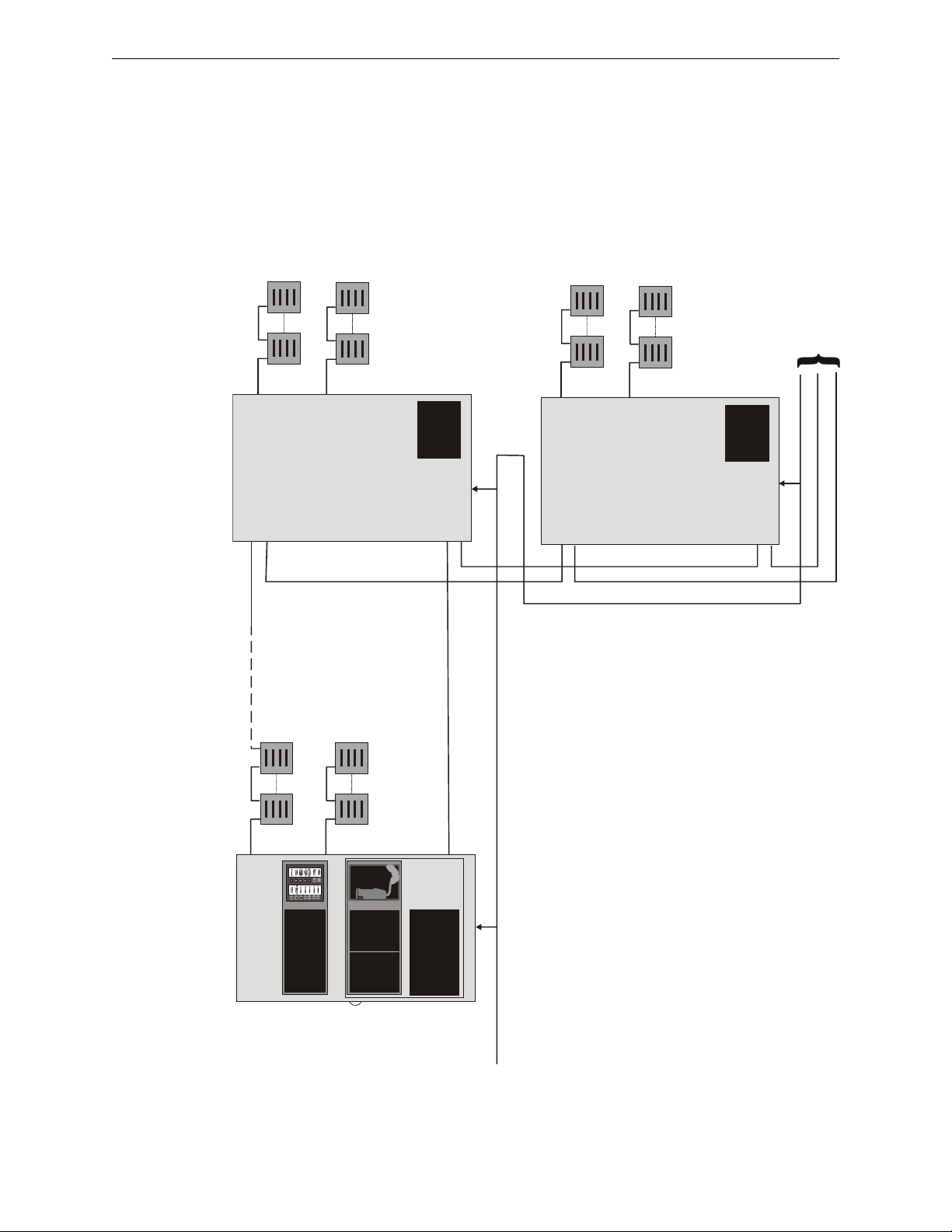
Audio Riser
25W Speaker Circuit
25W Speaker Circuit
Master Command Bus
FACP Control
ACC-25/50
FACP Control
Master Command Bus
Audio Riser
To Additional ACC-25/50DA Panels
25W Speaker Circuit
25W Speaker Circuit
25W Speaker Circuit
25W Speaker Circuit
ACC-25/50DA
ACC-25/50DA
ACC-25/50 System
Audio Command Center System Diagram
The FireVoice (ACC-25/50) can be used for systems
requiring up to 50 watts of audio power. Compatible
FACPs can be used for automatic control.
The Distributed Audio Panel (ACC-25/50DA) can
be used to increase audio power above 50 watts.
1. The FACP contorls the audio system via the CMD
inputs on the ACC-25/50 and ACC-25/50DA.
2. The Audio Riser connects the audio output of the
ACC-25/50 to each of the ACC-25/50DA(s).
3. The Master Command Bus provides an All-Call trigger
from the ACC-25/50 to the ACC-25/50DA(s).
accdadistsys.wmf
10 Audio Command Center Series Manual — P/N 51889:E1 6/8/2010
Page 11
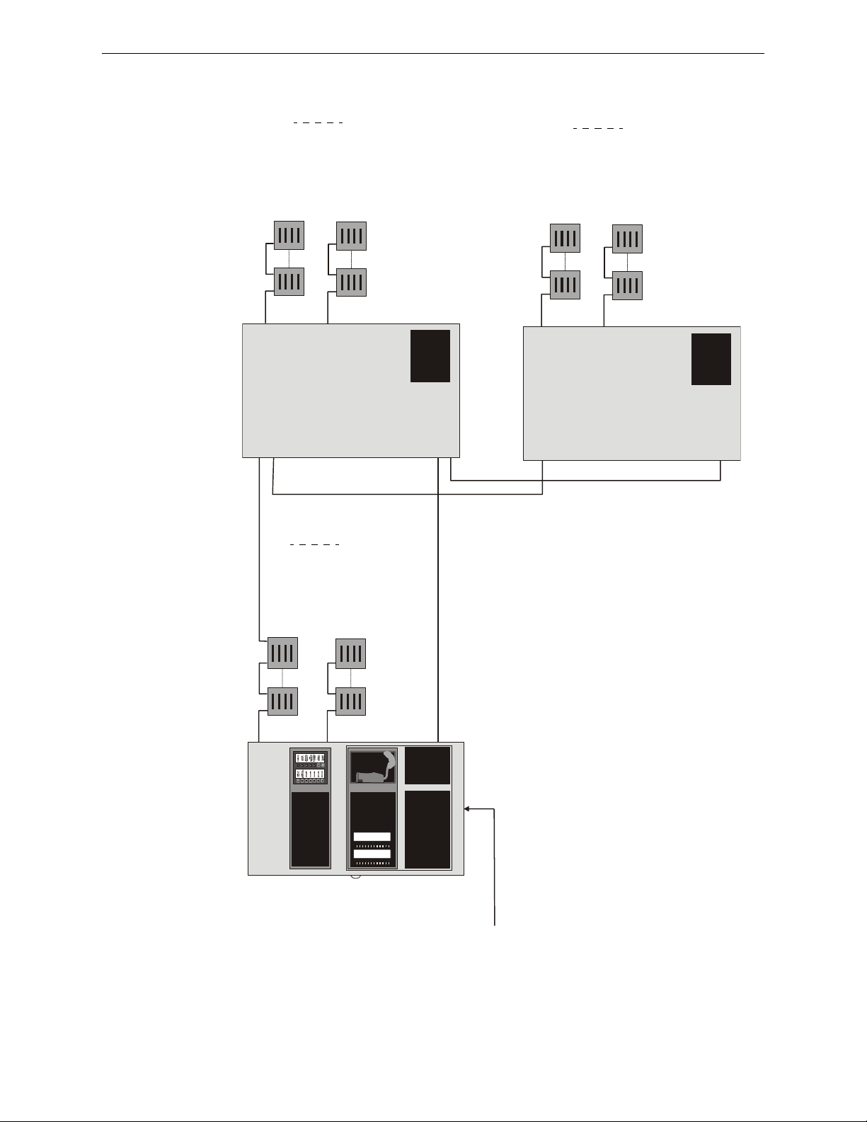
Audio Command Center Zone System
Up to 24 Zones @ 150W (max.)
Speaker Circuit #16
1. The FACP controls the audio system via the ACS Link or CMD
inputs on the ACC-25/50ZS
2. The Audio Riser connects the audio output of the ACC-25/50ZS to
each of the ACC-25/50DAZS(s) to distribute alarm or paging
audio.
3. The ACC-25/50ZS uses the Control Serial Link to control the
routing of the alarm or paging audio.
4. Riser conductors must be installed in accordance with the
survivability from attack by fire requirements in National Fire
Alarm Code, NFPA 72.
Speaker Circuit #9
Speaker Circuit #17
Speaker Circuit #24
ACC Control Serial Link (RS-485)
Audio Riser
Speaker Circuit #1
Speaker Circuit #8
ACC Control Serial Link (RS-485)
Automatic Control via the
ACS Link or CMD Input
ACC-25/50DAZS
ACC-25/50ZS
ACC-25/50DAZS
ACCDAZSDISTSYS2.wmf
Audio Riser
Audio Command Center Series Manual — P/N 51889:E1 6/8/2010 11
Page 12
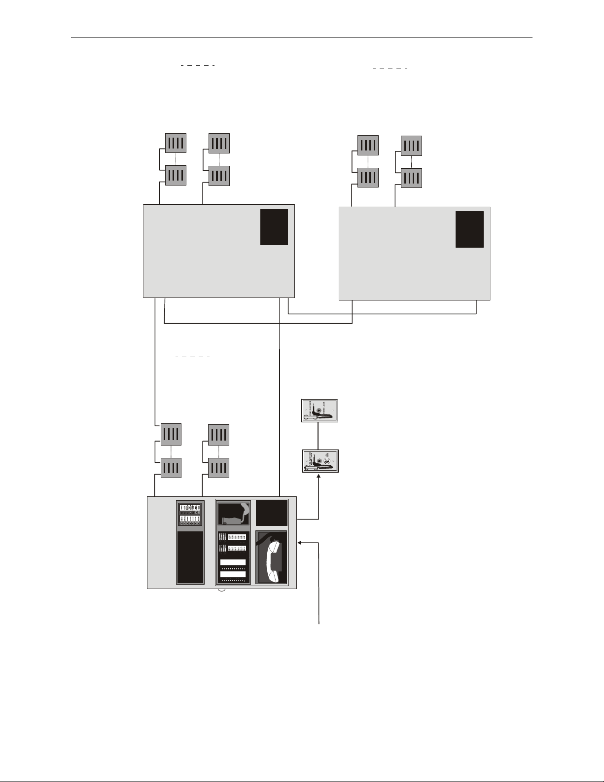
Speaker Circuit #16
1. The FACP controls the audio system via the ACS Link or CMD
inputs on the ACC-25/50ZST.
2. The Audio Riser connects the audio output of the ACC-25/50ZST to
each of the ACC-25/50DAZS(s) to distribute alarm or paging audio.
3. The ACC-25/50ZST uses the Control Serial Link to control the
routing of the alarm or paging audio.
4. Riser conductors must be installed in accordance with the
survivability from attack by fire requirements in National Fire Alarm
Code, NFPA 72.
Speaker Circuit #9
Speaker Circuit #17
Speaker Circuit #24
ACC Control Serial Link (RS-485)
Audio Riser
Speaker Circuit #1
Speaker Circuit #8
ACC Control Serial Link (RS-485)
Automatic Control via the
ACS Link or CMD Input
ACC-25/50DAZS
ACC-25/50ZST
ACC-25/50DAZS
Audio Riser
RPJ-F
FPJ-F
up to 24 remote
FireFighter
Telephones
Audio Command Center Zone System With FireFighter Telephone
Up to 24 Zones @ 150W (max.)
ACCDAZSDISTSYS3.wmf
12 Audio Command Center Series Manual — P/N 51889:E1 6/8/2010
Page 13

Section 1: Product Description
The ACC-25/50 Series consists of the AUDIO•COMMAND•CENTER•25/50 (ACC-25/50), the
AUDIO•COMMAND•CENTER•25/50 Zone System (ACC-25/50ZS), and the AUDIO•COMMAND•CENTER•25/50 Zone System with Telephone (ACC-25/50ZST) which are single channel,
25 watt, 25 VRMS, emergency voice evacuation panels. The ACC-25/50 provides up to two
speaker circuits while the ACC-25/50ZS and ACC-25/50ZST support up to eight speaker circuits.
Each panel provides the ability to record five field programmable messages (up to 60 seconds total
message duration) with an integral microphone or from an external audio source. An integral
power supply with battery charger supplies operational power. An ACC-AAM25 audio amplifier is
provided standard with each base unit. An optional second ACC-AAM25 amplifier is also available for backup purposes or to provide an additional channel of 25 watts. Optional 70 VRMS conversion modules are also available for installations where 70 VRMS speakers are to be installed or
already exist. An optional External Page Module (ACC-EPM) is available for interfacing to nonfire
paging systems. The modular design allows for ease-of-serviceability.
Automatic activation of the ACC-25/50 by an FACP is possible via the five Command Input Circuits (CMD). The ACC-25/50ZS and ACC-25/50ZST can be automatically activated by the CMD
inputs or via the ACS serial communications link from the MS-9600, MS-9200UDLS, MS9200UD, MS-9200(E) and MS-5210UD FACPs.
Two Command Input Circuits can be independently field programmed for activation by an FACP
Notification Appliance Circuit reverse polarity or by closure of a supervised normally open contact
and three Command Input Circuits activate on contact closure. CMD 1 and CMD 2 provide terminals for NAC input and output to allow installation of the audio panel anywhere along the NAC circuit being used to activate it. Options via the Command Inputs allow one 60 second message, two
30 second messages, three 20 second messages, four 15 second messages or five 12 second messages.
The ACC-25/50ZS and ACC-25/50ZST include an ACC-ZPMK Zone Page Module with keypad
and an ACC-ZSM Zone Splitter Module. These modules provide up to eight speaker circuits that
may be manually or automatically activated.
The ACC-25/50ZST includes an ACC-FFT Fire Fighter Telephone Module with keypad which
provides indications of phone activation, remote page activation, remote microphone activation and
corresponding trouble conditions. Additionally, up to 24 telephone circuits can be annunciated at
the ACC-FFT by connecting addressable monitor modules to the optional FPJ-F or RPJ-F Remote
Page Jacks.
Significant technological enhancements set the ACC-25/50 Series apart from other voice panels.
These enhancements include full supervision in both active (alarm or music) and standby conditions. Supervision is provided for:
amplifier outputs
field wiring (shorts and opens)
message generator
all tone generators
microphone
telephones (optional)
If the message generator fails, the system automatically reverts to the primary tone generator. If the
primary tone generator fails, one of three backups become enabled.
Power is fed independently
to each amplifier so that a short circuit in one amplifier will not shut
down the other. Full output power of 25 watts per amplifier is generated while in a low battery condition. Power is not diminished when the optional 70 V
transformer module is installed. Audio
RMS
is amplified utilizing modern integrated circuits as opposed to transformer technology. This provides for very low signal distortion for crystal clear audio.
Audio Command Center Series Manual — P/N 51889:E1 6/8/2010 13
Page 14

Product Description Product Features
Primary applications for the audio panels include structures such as restaurants, schools, auditoriums, places of worship, buildings with occupancies over 50, etc. The ACC-25/50 Series is
designed to interface directly to addressable or conventional fire alarm control panels or can be
used with the Audio Command Center Distributed Audio (ACC-25/50DA) panel to distribute audio
in systems that require more than 50 watts.
1.1 Product Features
• 25 watts of 25 V
• Optional 70.7 V
audio power (expandable to 50 watts) per panel
RMS
conversion module available for each amplifier (note that speaker wiring
RMS
continues to be supervised in standby, alarm and when background music is playing with this
option module installed)
• Modular design for maximum system flexibility
• Unobstructed module access and removable terminal blocks for ease of servicing and module
replacement
• Designed to allow easy system expansion
• Five Command Input Circuits:
CMD1 and CMD2 are field selectable to be activated from 12 or 24 VDC Notification
Appliance Circuits (reverse polarity) or contact closures
CMD3, CMD4, and CMD5 are activated by contact closures
• Speaker Circuits
single Style Y or Z speaker circuit (one ACC-AAM25 Audio Amplifier provided with base
unit)
two Style Y or Style Z speaker circuits (with optional second ACC-AAM25 Audio
Amplifier installed)
eight Style Y or four Style Z speaker circuits (only on ACC-25/50ZS or ACC-25/50ZST
Panel with ACC-ZSM Zone Splitter Module)
• ACC-25/50ZS and ACC-25/50ZST can be controlled by an FACP via the ACS (EIA-485) link
to the ACC-ZPMK. ACS compatible FACPs include the MS-9600, MS-9200(E), MS9200UD, MS-9200UDLS and MS-5210UD.
• Integral supervised microphone
• Microphone time-out feature which reverts back to prerecorded message if emergency page
exceeds three minutes
• Standard, prerecorded message:
“May I have your attention please. May I have your attention please. The signal you
have just heard indicates a report of a fire in this building. Please proceed to the nearest
exit and leave the building. Do not re-enter the building unless directed to do so by the
proper authorities.”
• Field-selectable message and custom message field recording capability using local
microphone or two compatible audio input jacks
• Two External Audio Inputs for recording custom message from compatible source or playing
music over the system with prior approval of the local Authority Having Jurisdiction (AHJ)
• Multiple duration message capability: one 60 second, two 30 second, three 20 second, four 15
second or five 12 second custom messages
• Integral tone generators field selectable for steady, slow-whoop, high-low or chime tones
• Higher wattage capability available by using the Audio Command Center Distributed Audio
(ACC-25/50DA) panel
• Powered by integral AC power supply or batteries during AC fail
• Programmable delay of immediate, 2 hours or 6 hours reporting of AC Loss
• Piezo sounder for local trouble
14 Audio Command Center Series Manual — P/N 51889:E1 6/8/2010
Page 15

Product Features Product Description
• Two Form-C trouble relays:
System Trouble Relay - TB1
AC Power Loss Relay - TB7
• 35 mA Special Application (auxiliary power) output for addressable modules when interfaced
with the Fire•Lite MS-9200(E) or MS-9600 FACP or equivalent and End-of-Line power
supervision relays
• Integral Dress Panel
• Optional ACC-TR semi-flush trim ring
• ACC-FFT Fire Fighter Telephone module for control and annunciation of up to 24 remote
telephone jacks (installation in ACC-25/50ZST only)
• Fire Fighter Handset (FHS-F) used to communicate over the telephone circuit connected to the
ACC-FFT (ACC-25/50ZST only)
• Fire Fighter Phone Jack FPJ-F provides plug-in location for the FHS-F (ACC-25/50ZST only)
• Remote Page Jack RPJ-F provides plug-in location for the FHS-F and All-Call paging
capability (ACC-25/50ZST only)
• Fire Fighter Handset Cabinet FHSC-RF (recess mount) or FHSC-SF (surface mount) is used to
store five Fire Fighter Handsets (FHS-F) (ACC-25/50ZST only)
• Optional FC-RM Remote Microphone (includes cabinet and FC-MIM Microphone Interface
Module). Refer to the FC-RM Product Installation Document #51247 for additional
information
• Optional ACC-EPM External Page Module for interfacing to non-fire paging systems
• Optional local playback speaker (FC-LPS)
• System Status LEDs (refer to “Controls and Indicators” on page 23)
• Master Command Bus output for All-Call paging control of Distributed Audio panels in non-
zone split systems
Audio Command Center Series Manual — P/N 51889:E1 6/8/2010 15
Page 16
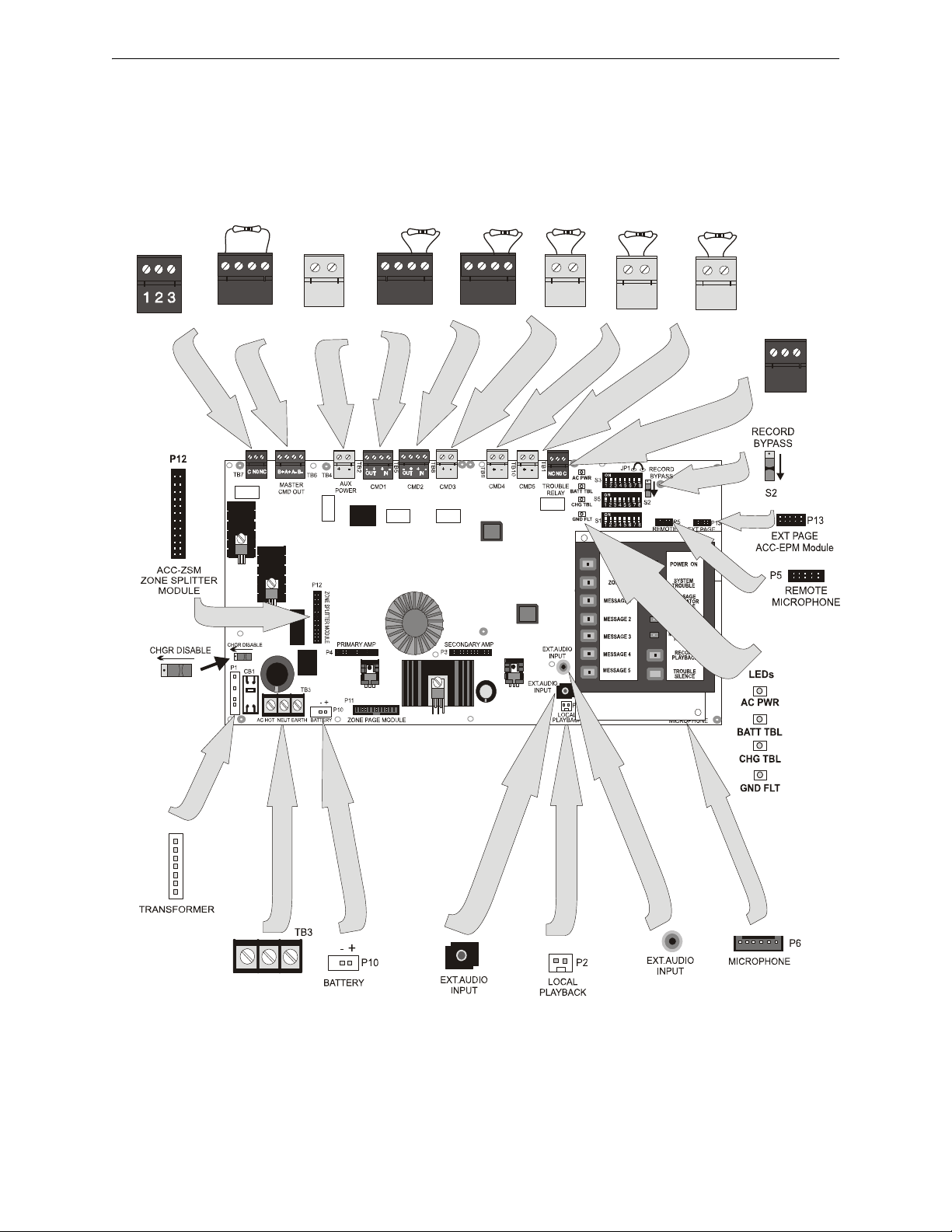
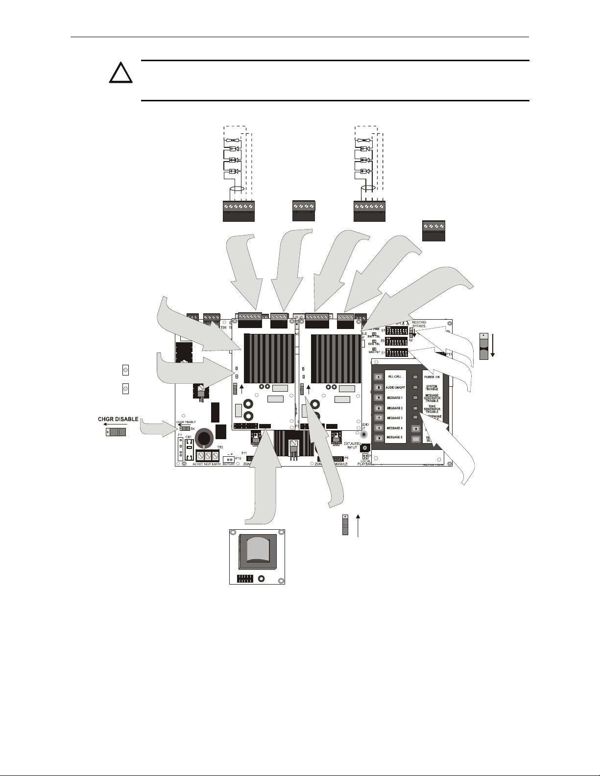
AUX
POWER
CMD1
CMD2
CMD3
CMD4
CMD5
MASTER
CMD OUT
AC LO SS
TB4
TB2 TB5
TB8
TB9
TB10
TB6
TB7
P1
TB1
NC NO C
C NO NC
1 2
1 2 3
1 2 3 4 1 2 3 4 1 2 3 4
Form-C AC
Loss Relay
nonsupervised
Programmable
Output Trigger -
(supervised, power-
limited) activation by
Emergency and
Nonemergency
paging - active
polarity shown
4.7K ELR ½ watt
P/N: 27072
+ + - -
+ -
Special
Application
Power 35 mA
(nonsupervised,
power-limited)
- + + -
CMD1 Input
Trigger by contact
closure or NAC
reverse polarity
(ELR required) -
alarm polarity
shown
OUT IN
CMD2 Input
Trigger by contact
closure or NAC
reverse polarity
(ELR required) -
alarm polarity
shown
OUT IN
Form-C Trouble
Relay
(nonsupervised)
Connector P5
FC-MIM or
ACC-FFT
Local Speaker
Connector
RCA Jack
Local Microphone
Connector
HOT
NEUTRAL
EARTH
Connector for
Transformer
ac25mnt1.wmfR
AC Power Only (supervised,
nonpower-limited)
Refer to AC Power in Section
“Specifications” on page 19
Personal
Computer
Source
- + + -
+ -
+ -
+ -
CMD3, CMD4 & CMD5 Input
Trigger by contact closure
alarm polarity shown (inputs only)
ACC-ZSM
All CMD inputs are supervised, power-limited. When contact closure is
employed, a 4.7K ELR, P/N: 27072 is required.
(supervised,
nonpower-limited)
Figure 1.1 Audio Command Center Board
Product Description Product Features
16 Audio Command Center Series Manual — P/N 51889:E1 6/8/2010
Page 17
Product Features Product Description
!
J1
T1
TB1 TB2
P1
SW1
BACK-UP ON
CKT TBL
AMP SUPV
J1
TB1 TB2
P1
SW1
BACK-UP ON
CKT TBL
AMP SUPV
J1
TB2
TB2
TB1 TB1
1 2 3 4 5 6
1 2 3 4 5 6
1 2 3 4
1 2 3 4
S2
S1
BACK-UP ON
+ - + -
+ - + -
S4
AC25MNT2.wmf
+ - + -
+ - + -
Speaker Circuits are supervised
and power-limited
ELR Resistor required only for
Style Y (Class B) circuits.
4.75 K, 1 watt P/N: 75470
Figure 1.2 Command Board With Amplifiers
Backup Audio
In Out
Backup Audio
In Out
Optional 2nd or
Backup Amplifier
ACC-AAM25
Field
Programmable
Option Switches
S3, S5, and S1
Controls and
System Status
Indicators
(Switch S1 of 2nd amplifier
shown in Backup ‘OFF’ condition
FC-XRM70
Optional 70.7 VRMS Plug-in
Conversion Module
(available for each amplifier)
Battery Charger
Disable Switch
(switch shown for
charger enabled)
LEDs on each amplifer
Amp
Supervision
Circuit
Trouble
Standard
Main Amplifier #1
ACC-AAM25
CAUTION: OBSERVE PROPER POLARITY
MATCH PROPER POLARITY CONNECTIONS TO FIELD WIRING AND SPEAKERS. POLARITY
SHOWN IS IN THE STANDBY AND ALARM CONDITIONS.
Audio Command Center Series Manual — P/N 51889:E1 6/8/2010 17
Page 18
Product Description Product Features
TB1 TB2
P1
SW1
BACK-UP ON
CKT TBL
AMP SUPV
J1
TB1 TB2
P1
SW1
BACK-UP ON
CKT TBL
AMP SUPV
J1
TB1
J1
1 2 3 4 5 6 7 8
ON
S1
ON
S3
0
5
4
3
2
1
9
8
7
6
0
5
4
3
2
1
9
8
7
6
S2
TENS
ONES
AAM
1 & 2
AAM1
JP1
TB1
TB9
TB4
SW2
SW1
TB5
TB6
CLASS A
CLASS B
1 2 3 4 5 6 7 8
ON
S1
S3
0
5
4
3
2
1
9
8
7
6
0
5
4
3
2
1
9
8
7
6
S2
AAM
1 & 2
AAM1
SW2
SW1
TB1
TB9
TB4
TB5
TB6
+ -
+ -
+
-
+
-
+
-
+
-
+
-
+
-
+
-
+
-
TB1
TB2
TB1
TB4
TB5
TB6
+
-
+
-
+
-
+
-
+
-
+
-
+
-
+
-
+
+
-
-
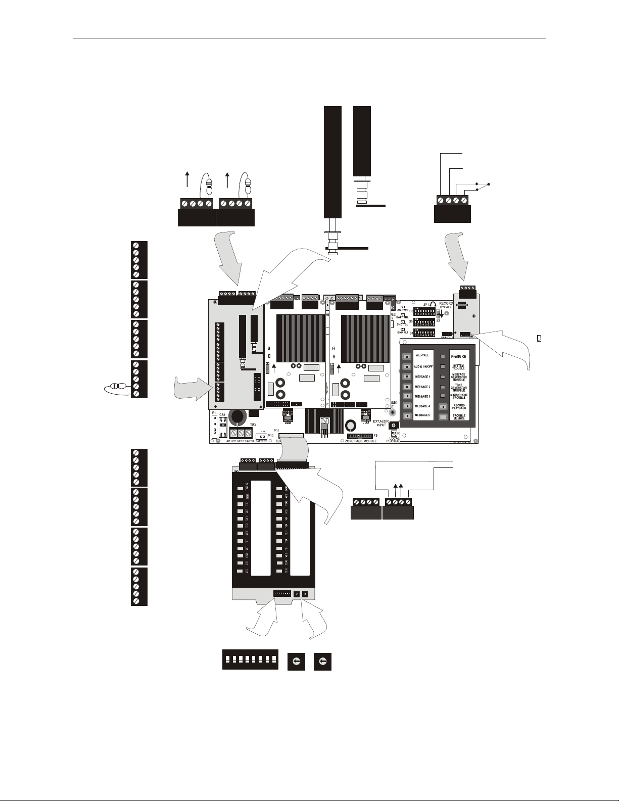
Figure 1.3 ACC-25/50ZS Main Board With Modules
AC25ZSMNTa.wmf
1 2 3 4 1 2 3 4
Circuits are power-limited and
supervised and require ELRs
4.75K P/N: 27589
1 2 3 4
1 2 3 4
1 2 3 4
5
4
3
2
1
5
4
3
2
1
5
4
3
2
1
5
4
3
2
1
5
4
3
2
1
5
4
3
2
1
5
4
3
2
1
5
4
3
2
1
Speaker Circuits are
supervised, power-limited
supervised
(nonsupervised)
Style Y (Class B)
To Speakers
To Speakers
To Speakers
To Speakers
To Speakers
To Speakers
To Speakers
shield
shield
shield
shield
Dummy Load all
unused circuits with
4.75 K resistor
Style Z (Class A)
To Speakers
shield
Speaker Return
Page
Active
LED
To Speakers
shield
Speaker Return
To Speakers
shield
Speaker Return
To Speakers
shield
Speaker Return
Jumper all unused circuits:
+ to + and - to -
Field Programmable
Option Switches for
Speaker Circuits
ACS Addressing
Switches for EIA-485
Communications with
FACP
ON
TENS ONES
ACC-ZPMK
Zone Page Module
ACS (EIA-485)
Link to FACP
to ACS devices down-stream
ACC-EPM
External Page Module
Class A
Class B
from external page
system audio
(600, 700 mV
RMS
)
contact closure
from external
page system
Select 4 Class
A or 8 Class B
Speaker
Circuits
(shown for 8
Class B
Speaker
Circuits)
To Amplifier #1
To Amplifier #2
Select Single
or Split
Amplifier
Configuration
(shown set for
Split Amplifier
configuration)
ACC-ZSM
Zone Splitter
Module
Zone 1
Zone 2
Zone 3
Zone 4
Zone 5
Zone 6
Zone 7
Zone 8
Zone 1
Zone 2
Zone 3
Zone 4
ACC-25/50ZS Modules
18 Audio Command Center Series Manual — P/N 51889:E1 6/8/2010
Page 19
Specifications Product Description
TB1 TB2
P1
SW1
BACK-UP ON
CKT TBL
AMP SUPV
J1
TB1 TB2
P1
SW1
BACK-UP ON
CKT TBL
AMP SUPV
J1
1 2 3 4 5 6 7 8
ON
S1
ON
S3
0
5
4
3
2
1
9
8
7
6
0
5
4
3
2
1
9
8
7
6
S2
TENS
ONES
AAM
1 & 2
AAM1
JP1
TB1
TB9
TB4
SW2
SW1
TB5
TB6
CLASS A
CLASS B
SW1
J1
TB1
TB2
TB3
FFT 1
FFT 2
FFT 3
FFT 4
FFT 5
FFT 6
FFT 7
FFT 8
FFT 9
FFT 10
FFT 11
FFT 12
FFT 13
FFT 14
FFT 15
FFT 16
FFT 17
FFT 18
FFT 19
FFT 20
FFT 21
FFT 22
FFT 23
FFT 24
SW1
TB1
TB2
TB3
J3J2J1
1 2 3 4 5 6
1 2 3 4 5 6
1 2
SW2
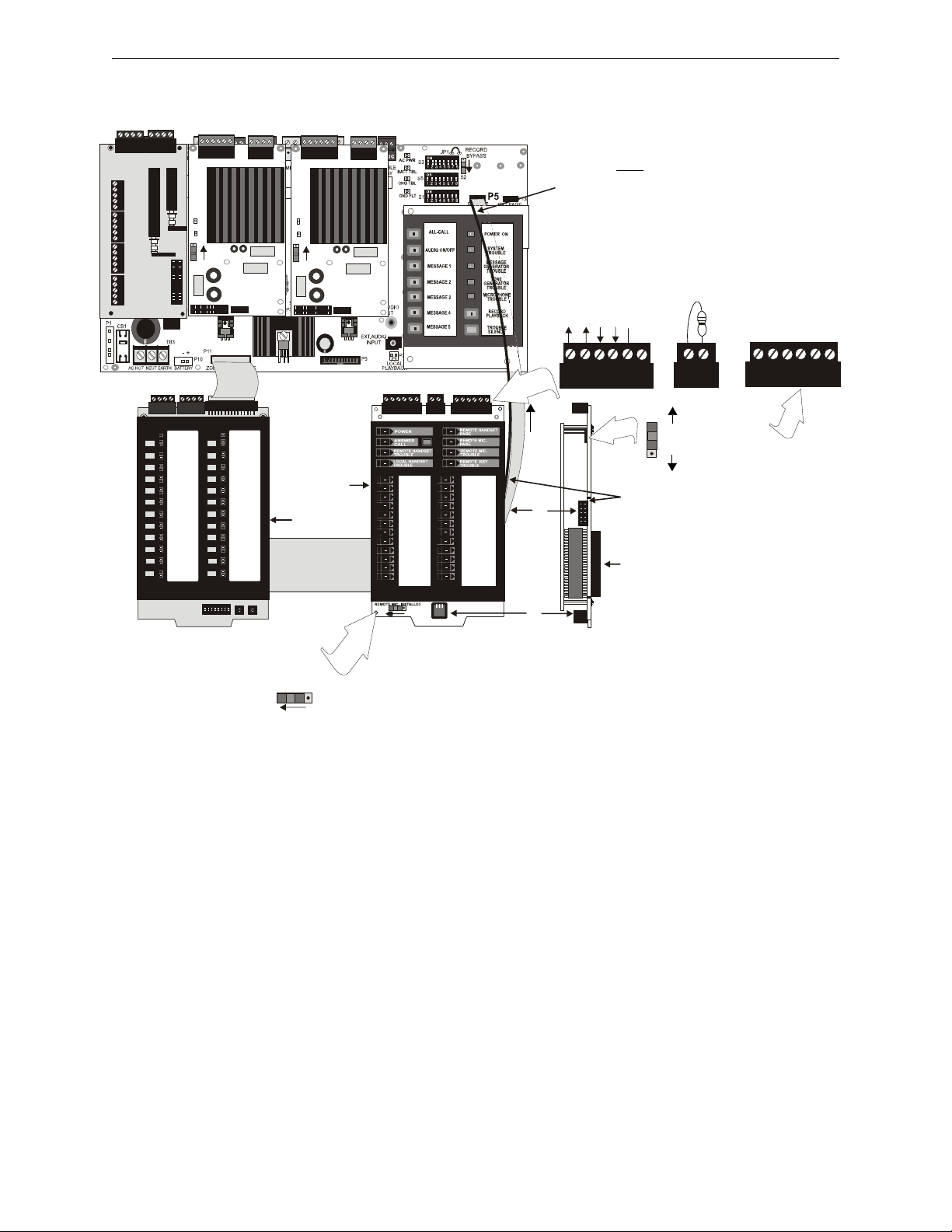
Figure 1.4 ACC-25/50ZST Main Board with ACC-FFT Module
AC25ZSTMNTa.wmf
Dark stripe on
ribbon cable must
be positioned to
left as shown!!
Remote
Microphone
Wiring
Power
Grnd
+ Audio
- Audio
Earth
Remote Page
Jack Keyswitch
used for All-Call
Phone Paging
(4.7K ELR
required after
last RPJ
Keyswitch or at
TB2 if
Keyswitch is
not used)
Class A Class B
Return Out
+ shld - + shld -
Audio Wiring to
Remote Page
Jack (4.7K ELR
required after last
RPJ for Class B
wiring only)
switch position
shown for
2-wire Class B
telephone
connection
2-wire
4-wire
(ribbon cable is required when
annunciating remote Fire Fighter
Telephone locations)
to P5
on
main
board
Panel FFT
Handset
Connector
(side view)
Fire Fighter
Telephone Module
REMOTE MIC INSTALLED
switch position shown
for remote
microphone installed
Zone Page Module
Ribbon
Cable from
J3 on back
of
to P4 on
back of
ACC-25/50ZST with ACC-FFT Module
1.2 Specifications
AC Power - TB3
ACC-25/50, ACC-25/50ZS, ACC-25/50ZST: 120 VAC, 60 Hz, 1.5 amp.
Wire size: minimum #14 AWGb with 600 V insulation.
AC Loss Relay - TB7
Operation: normally energized fail-safe relay transfers on AC power loss for independent monitoring by DACT. AC Loss Relay can be programmed to be the only indication of an AC loss condition (see Table 2.3 on page 34).
AC Loss relay contact rating: 2.0 amps @ 30 VDC (resistive), 0.6 amps @ 30 VAC (resistive)
Audio Command Center Series Manual — P/N 51889:E1 6/8/2010 19
Page 20

Product Description Specifications
Battery (lead acid only) - P10
Maximum Charging Circuit: Normal Flat Charge - 27.6V @ 0.800 amp
Maximum Charger Capacity: 18 Amp Hour battery. (Audio Command Center Series cabinet holds
max. 18 Amp Hour Battery.
Command Input Circuits (alarm polarities shown)
• CMD1 - TB2 Terminals 3(+) & 4(-) are input terminals and Terminals 1(-) and 2(+) are output
terminals which provide feed through of the NAC circuits to NAC devices down stream
• CMD2 - TB5 Terminals 3(+) & 4(-) are input terminals and Terminals 1(-) and 2(+) are output
terminals which provide feed through of the NAC circuits to NAC devices down stream
• CMD3 - TB8 Terminals 1(+) & 2(-) are input terminals for contact closure only
• CMD4 - TB9 Terminals 1(+) & 2(-) are input terminals for contact closure only
• CMD5 - TB10 Terminals 1(+) & 2(-) are input terminals for contact closure only
Operation: CMD1 & CMD2 circuits are independently field programmable to activate amplifiers
on NAC polarity reversal or contact-closure. IMPORTANT! When CMD1 and CMD2 are config-
ured for reverse polarity, the NAC cannot
be Coded.
CMD3, CMD4 and CMD5 are fixed to activate on contact closure only. End-of-Line resistors must
be connected in all configurations.
Power-limited and supervised circuitry
Normal Operating Voltage Range: 10.5 VDC - 29 VDC; Maximum Voltage: 29 VDC
NAC Reverse Polarity Current (requires End-of-Line Resistor from NAC): 1.6 mA maximum.
Contact Closure Operation Current (requires 4.7K, ½ watt End-of-Line Resistor P/N 27072): 6.6
mA maximum
Maximum Wiring Impedance CMD1 - CMD5 (Contact Closure Operation): 200
Maximum Input Impedance:
• CMD1 & CMD2 (Reverse Polarity Operation): 20K
• CMD1 - CMD5 (Contact Closure Operation): 3.4K
Audio Amplifier Module
Standard ACC-AAM25 Amplifier plugs into P4 of main circuit board, optional ACC-AAM25
Amplifier plugs into P3 of main circuit board
Backup Audio - TB2 [In Terminals 1(+) & 2(-), Out Terminals 3(+) & 4(-)] on Amplifier Module
Operation: When TB2 is wired between the two amplifiers of a panel, the optional amplifier provides backup to the standard amplifier. Switch S1 on the backup amplifier must be 'ON' and jumpers placed from backup amplifier TB2 Terminal 3 to standard amplifier TB2 Terminal 1 and from
backup amplifier TB2 Terminal 4 to standard amplifier TB2 Terminal 2. Refer to Section “One
Speaker Circuit With Backup on ACC-25/50” on page 81, for additional information.
Speaker Circuit - TB1 Terminals 3(+) & 4(-) Style Y, 5(+) & 6(-) Style Z, 1 & 2 Shield (Standby
and Alarm Polarity Shown) on Amplifier Module
Power-limited circuitry
Operation: Circuit can be wired Style Y or Style Z
Normal Operating Voltage: 25 V
(70.7 V
@ 350 mA max. with maximum Load Impedance of 200operation possible by plug-
RMS
@ 1 amp max. and maximum Load Impedance of 25
RMS
ging optional FC-XRM70 conversion module into P1 of audio amplifier).
Circuit wiring is supervised during standby, alarm and when background music is playing
Output Power: 25 watts (20 watts when background music is employed);
Frequency Range: 800Hz - 2,800Hz
Maximum total capacitance for each speaker circuit: 250 µF.
End-of-Line Resistor required for Style Y circuit: 4.75 K, 1 watt (P/N: 75470)
20 Audio Command Center Series Manual — P/N 51889:E1 6/8/2010
Page 21

Specifications Product Description
ACC-ZSM Zone Splitter Module and ACC-ZPMK Zone Page Module (ACC-25/50ZS/T
Only)
Power-limited circuitry
Operation: Circuits on ACC-ZSM can be wired as eight Style Y or four Style Z
Normal Operating Voltage for Speaker Circuits: 25 V
@ 1 amp max. and maximum Load
RMS
Impedance of 25
(70.0 V
@ 350 mA max. with maximum Load Impedance of 200operation possible by
RMS
plugging optional FC-XRM70 conversion module into P1 of audio amplifier).
Speaker circuit wiring is supervised during standby and alarm. (Note that background music is not
permitted in Zone Splitter configuration since open-circuit fault detection is not possible)
Output Power: 25 watts total; Frequency Range: 800Hz - 2,800Hz
Maximum total capacitance for ACC-AAM25: 250 µF. (Note that the total
capacitance for the
ACC-ZSM speaker outputs must not exceed the maximum of 250 µF).
End-of-Line Resistor required for Style Y (Class B) speaker circuit: 4.75 K, 1 watt (P/N: 75470)
TB1 on ACC-ZPMK: ACS (EIA-485) electrically isolated link to FACP provides programmed
speaker control
ACC-FFT Fire Fighter Telephone Module (ACC-25/50ZST Only)
Power-limited circuitry
TB1 Remote Phone Circuit Operation: Circuit can be wired Style Y (Class B) or Style Z (Class A)
Wiring connects Remote Page Jacks (FPJ-F or RPJ-F) to control panel for phone communication
Normal Operating Voltage (V
): Standby = n/a, Active = 0.2 V
RMS
RMS
Normal Operating Voltage (VDC): Standby = 12 VDC, Active = 4 VDC to 0.9 VDC
Normal Operating Current (mA): Standby = 1.3 mA, Active = 5 mA
Circuit wiring is supervised.
Maximum wiring impedance = 54
End-of-Line Resistor required for Style Y circuit: 4.7K, ½ watt
TB2 Remote Page Jack Keyswitch Operation: Circuit wired Class B
Keyswitch enables All-Call Paging by FHS-F Remote Phone
Requires RPJ-F
Circuit wiring is supervised.
Maximum wiring impedance = 54
End-of-Line Resistor required: 4.7K, ½ watt
TB3 Remote Microphone Operation:
Provide connection for the optional FC-RM Remote Microphone Module which is used for remote
paging capabilities.
NOTE: For installations that require both the Fire Fighter Telephone and Remote Microphone,
the Remote Microphone Module wiring connections are made to the ACC-FFT Fire Fighter
Telephone Module.
Master CMD Out - TB6 Terminals 1(+), 2(+), 3(-) & 4(-) (active polarity shown)
Provides All-Call Paging trigger for Distributed Audio units (ACC-25/50 ONLY). Will drive MR101C or MR-201C relays (manufactured by Air Products and Controls) to provide relay contacts.
Supervised and power-limited circuitry
Programmed Operation: Output reverses polarity on activation of All-Call switch, Remote Microphone or External Page Module input.
Normal Operating Voltage: 24 VDC regulated, filtered; Maximum Voltage: 25.4 VDC
Reverse Polarity Current: 125 mA maximum.
Standby Voltage: -5 VDC. Short Circuit Current: 0.5 mA. Maximum Load Resistance: 200 ohms.
Wiring connections to Master CMD Output Circuit:
Audio Command Center Series Manual — P/N 51889:E1 6/8/2010 21
Page 22

Product Description Specifications
End-of-Line Resistor required for Class B using Terminals 1(+) & 4(-): 4.7 K, ½ watt
(P/N: 27072)
Class A (no End-of-Line Resistor) requires the wiring of Terminal 1(+) to 2(+) and Terminal
3(-) to 4(-)
Up to 25 Distributed Audio Panels may be connected to this output (ACC-25/50 Only)
Special Application Power (Aux. Power) - TB4 Terminals 1(+) & 2(-)
Up to 35 mA @ 24 VDC of special application power is available for powering addressable modules and associated End-of-Line power supervision relays.
Power-limited circuitry. Refer to the Device Compatibility Document for a list of compatible
devices.
Form-C Trouble Relay - TB1
Normally energized fail-safe relay can be programmed to transfer its contacts on any panel trouble
condition or on any trouble condition except AC Loss (see Table 2.3 on page 34).
TB1 Form-C relay contact rating: 2.0 amps @ 30 VDC (resistive), 0.6 amps @ 30 VAC (resistive).
External Audio Input
• RCA Audio Jack Input (female connector)
nput Impedance: 30K maximum
Input Voltage: 700 mV
maximum
RMS
Input Current: 1 mA maximum @ 700 mV
Requires preamplifier output. Mates to an RCA phono 'plug' - 3mm diameter, 10mm
length, 9mm shell diameter.
• 3.5 mm PC Audio Jack Input (female connector)
Requires preamplifier output
Interfaces to personal computer line output
NOTE: Some laptop personal computers only provide an audio output for headphones. It may
be necessary to adjust the headphone output level for proper recording of voice messages.
FC-MIM Microphone Interface Module (Optional) - P5 Connector
Connector P5 provides a connection for:
• the optional FC-MIM Microphone Interface Module which is used to connect the FC-RM
Remote Microphone Module to provide remote microphone paging capabilities.
• the ACC-FFT Fire Fighter Telephone module which is used for emergency telephone appli-
cations.
NOTE: For systems that require both the Remote Microphone and Fire Fighter Telephone, the
ACC-FFT is connected to the P5 connector on the main circuit board and the Remote Microphone
connections are made on the ACC-FFT. The FC-MIM is incorporated into the ACC-FFT Fire
Fighter Telephone Module as part of the ACC-25/50ZST. A separate FC-MIM is therefore not
required for this system.
Microphone connector for Fire•Lite standard microphone P/N:45025 - P6 Connector
ACC-EPM External Page Module (Optional)
Audio Input Impedance: 600 maximum
Audio Input Voltage: 700 mV
maximum
RMS
Audio Input Current: 1 mA maximum @ 700 mV
Contact Closure Operation Current: 2.3 mA maximum
External paging equipment is electrically isolated from ACC-25/50, ACC-25/50ZS and ACC25/50ZST
22 Audio Command Center Series Manual — P/N 51889:E1 6/8/2010
Page 23

Controls and Indicators Product Description
Figure 1.5 Controls and Indicators
Single Zone Operation
acc25kyblnk.wmf
ALL-CALL
AUDIO ON/OFF
MESSAGE 1
MESSAGE 2
MESSAGE 3
MESSAGE 4
MESSAGE 5
POWER ON
SYSTEM
TROUBLE
MESSAGE
TROUBLE
GENERATOR
TONE
GENERATOR
TROUBLE
RECORD
PLAYBACK
TROUBLE
SILENCE
MICROPHONE
TROUBLE
Figure 1.6 Controls and Indicators
Dual Zone Operation
acc25kyblnk.wmf
ZONE 1
ZONE 2
MESSAGE 1
POWER ON
SYSTEM
TROUBLE
MESSAGE
TROUBLE
GENERATOR
TONE
GENERATOR
TROUBLE
RECORD
PLAYBACK
TROUBLE
SILENCE
MICROPHONE
TROUBLE
1.3 Controls and Indicators
1.3.1 Single Zone Operation (ACC-25/50, ACC-25/50ZS, ACC25/50ZST)
Figure 1.5 depicts Single Zone operation with the
maximum capacity of five messages. Single Zone
may be configured for two to five message control
(refer to Section 2, ”Field Programming” on page 32).
• ALL-CALL:
used to select All Call function when ACC-
25/50 Series is programmed for Single Zone
operation. Selecting this button also activates
the Master Command Bus, which is used to
trigger Distributed Audio Panels. Single Zone
operation directs the same message to both
amplifier circuits (S3 DIP switches 1, 2 and 3
set to one of the valid options other than all
OFF)
• AUDIO ON/OFF:
used to indicate that speaker circuits are activated when ACC-25/50 Series is programmed
for Single Zone operation (S3 DIP switches 1, 2 and 3 set to one of the valid options other
than all OFF). Push-button switch can be used to deactivate the audio amplifiers that were
activated by the FACP
• MESSAGE 1 - used to manually transmit Message 1 over speaker circuit
• MESSAGE 2 - used to manually transmit Message 2 over speaker circuit
• MESSAGE 3 - used to manually transmit Message 3 over speaker circuit
• MESSAGE 4 - used to manually transmit Message 4 over speaker circuit
• MESSAGE 5 - used to manually transmit Message 5 over speaker circuit
1.3.2 Dual Zone Operation (ACC-25/50 Only)
Figure 1.6 depicts Dual Zone operation which supports the generation of one message only (refer to Section 2, ”Field Programming” on page 32).
• ZONE 1:
• ZONE 2:
Audio Command Center Series Manual — P/N 51889:E1 6/8/2010 23
used to select Zone 1 when ACC-25/50 is
programmed for Dual Zone operation. Dual
Zone operation directs a single message to
either or both amplifier circuits (S3 DIP
switches 1, 2 and 3 set to OFF).
used to select Zone 2 when ACC-25/50 is
programmed for Dual Zone operation (S3 DIP
switches 1, 2 and 3 set to OFF)
Page 24

Product Description Controls and Indicators
FACP
ACC
Zone 1
Zone 2
Zone 3
Zone 4
Zone 5
Zone 6
Zone 7
Zone 8
Zone 24
Zone 9
Zone 10
Zone 11
Zone 12
Zone 13
Zone 14
Zone 15
Zone 16
Zone 17
Zone 18
Zone 19
Zone 20
Zone 21
Zone 22
Zone 23
1.3.3 RECORD/PLAYBACK
for recording messages when Record/Bypass switch is in the up Record position (refer to
Section “S2 - Record Bypass Switch on ACC-25/50 Series Motherboard (ACC-MCB)” on
page 38, Section 2.1, ”S1 DIP Switch Settings on ACC-25/50 Series Motherboard (ACCMCB)” on page 36 and Section 2.2, ”S5 DIP Switch Settings on ACC-25/50 Series
Motherboard (ACC-MCB)” on page 37 for additional information on recording messages.)
for reviewing recorded message when Record Bypass Switch is in the down Bypass position
(requires optional FC-LPS module).
1.3.4 TROUBLE SILENCE
momentary depression silences the local piezo when system is in trouble condition.
1.3.5 LEDs (visible with panel door closed):
• Power ON (green)
• System Trouble (yellow)
• Message Generator Trouble (yellow)
• Tone Generator Trouble (yellow)
• Microphone Trouble (yellow)
• Record/Playback (green)
•Dual Zone
Zone 1 (green = active, yellow = manual deactivation)
Zone 2 (green = active, yellow = manual deactivation)
• Message 1 (green = activation)
• Message 2 (green = activation)
• Message 3 (green = activation)
• Message 4 (green = activation)
• Message 5 (green = activation)
• Single Zone
All Call (green = active)
Audio On/Off (green = active, yellow = manual deactivation)
1.3.6 ACC-ZPMK Zone Page Module (ACC-25/50ZS and ACC25/50ZST Panels only)
Push button Switches
24 tactile push-button switches used to manually activate the corresponding speaker zone. If speaker zone has been activated by the
FACP programming, pressing the switch will deactivate the speaker
zone and illuminate the corresponding yellow zone LED and the System Trouble LED.
LEDs
• FACP Communication (green = active, extinguished = no
24 Audio Command Center Series Manual — P/N 51889:E1 6/8/2010
communication)
The (top left LED) communication should only be active if the
ACC-25/50ZS/T is connected to an FACP and communication
via the ACS link is established.
Page 25

Controls and Indicators Product Description
FFT 1
FFT 2
FFT 3
FFT 4
FFT 5
FFT 6
FFT 7
FFT 8
FFT 9
FFT 10
FFT 11
FFT 12
FFT 13
FFT 14
FFT 15
FFT 16
FFT 17
FFT 18
FFT 19
FFT 20
FFT 21
FFT 22
FFT 23
FFT 24
• ACC Communication (green = active, extinguished = no communication)
This (top right LED) indicates communication between the ACC-ZPMK and the ACC25/50ZS/T main circuit board via the connecting ribbon cable.
• Speaker Circuit Zones 1 through 24 (green = active, yellow = trouble/disabled
Only the LEDs for Zones 1 through 8 will be functional if the ACC-ZSM is configured for Style
Y (Class B) operation or only the LEDs for Zones 1 through 4 will be functional if the ACCZSM is configured for Style Z (Class A) and no ACC-25/25DAZS Distributed Audio panels are
connected.
1.3.7 ACC-FFT Fire Fighter Telephone Module (ACC-25/50ZST only)
Pushbutton Switches
• Answer Call - tactile pushbutton switch used to connect or
disconnect Remote Telephone FHS-F plugged into the FPJ-F or
RPJ-F from the ACC-FFT.
LEDs
• Power (green) - indicates that power is applied to the ACC-FFT
Fire Fighter Telephone module
• Answer Call (green LED) - flashes to indicate that a remote
phone (FHS-F) has been plugged into the FPJ-F or RPJ-F on the
telephone circuit. LED turns on steady when Answer/Call
pushbutton is pressed to answer the remote phone call
• Remote Handset Page (green LED) - turns on steady to indicate
that a remote phone (FHS-F) has been connected to the telephone circuit and the Remote Page
Jack Keyswitch on the RPJ-F has been activated for remote paging
• Remote Microphone Page (green LED) -turns on steady to indicate active paging from Remote
Microphone
• Remote Handset Trouble (yellow LED) - turns on steady to indicate that a fault exists on the
telephone circuit connected to TB1 of the ACC-FFT
• Local Handset Trouble (yellow LED) - turns on steady to indicate that the local handset has a
connection fault
• Remote Key Trouble (yellow LED) - turns on steady to indicate a remote keyswitch wiring
fault (TB2)
• Remote Microphone Trouble (yellow LED) - turns on steady to indicate a fault on the Remote
Microphone wiring or electronics (TB3)
• FFT 1 through FFT 24 (green LEDs) - LED for each of 24 possible remote phone circuits will
turn on if an addressable monitor module has been connected and programmed for activation
when a remote phone (FHS-F) is plugged into the corresponding Remote Page Jack (FPJ-F or
RPJ-F)
1.3.8 ACC-EPM External Page Module
• Page Active (green=active)
1.3.9 Other System LEDs (located on main circuit board and modules)
• AC Power (green) - main circuit board
• Battery Trouble (yellow) - main circuit board
• Charger Trouble (yellow) - main circuit board
• Ground Fault (yellow) - main circuit board
• Circuit Trouble (yellow) - Amplifier module
Audio Command Center Series Manual — P/N 51889:E1 6/8/2010 25
Page 26

Product Description Circuits
• Amplifier Supervision (green) - Amplifier module
1.4 Circuits
Input Circuits - CMD1, CMD2, CMD3, CMD4 & CMD5
• Input circuits CMD1 and CMD2 are independently field programmable to accept Notification
Appliance Circuits or normally open contacts. (IMPORTANT! When CMD1 and CMD2 are
configured for reverse polarity, the NAC cannot
feed-through of the NACs, allowing placement of the ACC-25/50 Series anywhere along a
Notification Appliance Circuit. A trouble on the ACC-25/50 Series will cause relay contacts at
the out terminals of CMD1 to open, causing an NAC circuit trouble at the FACP.
NOTE: The ACC-25/50 Series will not open the out terminals while in alarm or during AC loss if
the Trouble Relay is programmed not to transfer on AC Loss conditions (refer to Switch 8 in Table
2.3 on page 34). Monitoring ACC-25/50 Series troubles while in alarm requires use of
independent trouble relay at TB1.
• Programming CMD1 and/or CMD2 for activation on contact closure will allow activation of
the amplifiers on a normally open contact transfer to the closed condition. Contact wiring is
supervised for open conditions. A short will cause amplifier activation (contact closure).
• Input circuits CMD3, CMD4 and CMD5 will only activate on contact closure which will allow
activation of the amplifiers on a normally open contact transfer to the closed condition.
Contact wiring is supervised for open conditions.
Audio Input Jacks
• RCA Jack provides convenient connection to an audio source such as a tape player for
recording a new digital message. It may also be used for background music if approved by
local AHJ. Background music is prohibited during AC loss conditions to preserve battery
power.
• PC Jack provides convenient connection to an audio source such as a personal computer for
recording a new digital message. The jack allows vertical plug-in of a standard mini-jack
cable. It may also be used for background music if approved by local AHJ. Background music
is prohibited during AC loss conditions to preserve battery power.
Output Circuits
• Specific Application Power Output, 35 mA @ 24 VDC.
• Main circuit provides a 24 Volt Battery Charger (up to 18 AH batteries) @ 800 mA maximum.
Master Command Output Bus
• Normal Operating Voltage: 24 VDC regulated, filtered. Reverse Polarity Current 120 mA
maximum
• Output reverses polarity on activation
• All-Call Paging control bus for the Audio Command Center Distributed Audio panel (ACC25/50DA) or other Fire•Lite UL-listed audio products
Notification Appliance Circuit
• One NAC Speaker Circuit Style Y or Style Z with each ACC-AAM25 amplifier module.
• Four NAC Speaker Circuits Style Z or eight Style Y with ACC-ZSM (ACC-25/50ZS/T only)
Relays
• One Form-C Trouble Relay. Contacts are rated 2.0 amps @ 30 VDC (resistive) and 0.6 amps
@ 30 VAC (resistive)
be Coded). Terminals are provided to allow
26 Audio Command Center Series Manual — P/N 51889:E1 6/8/2010
Page 27
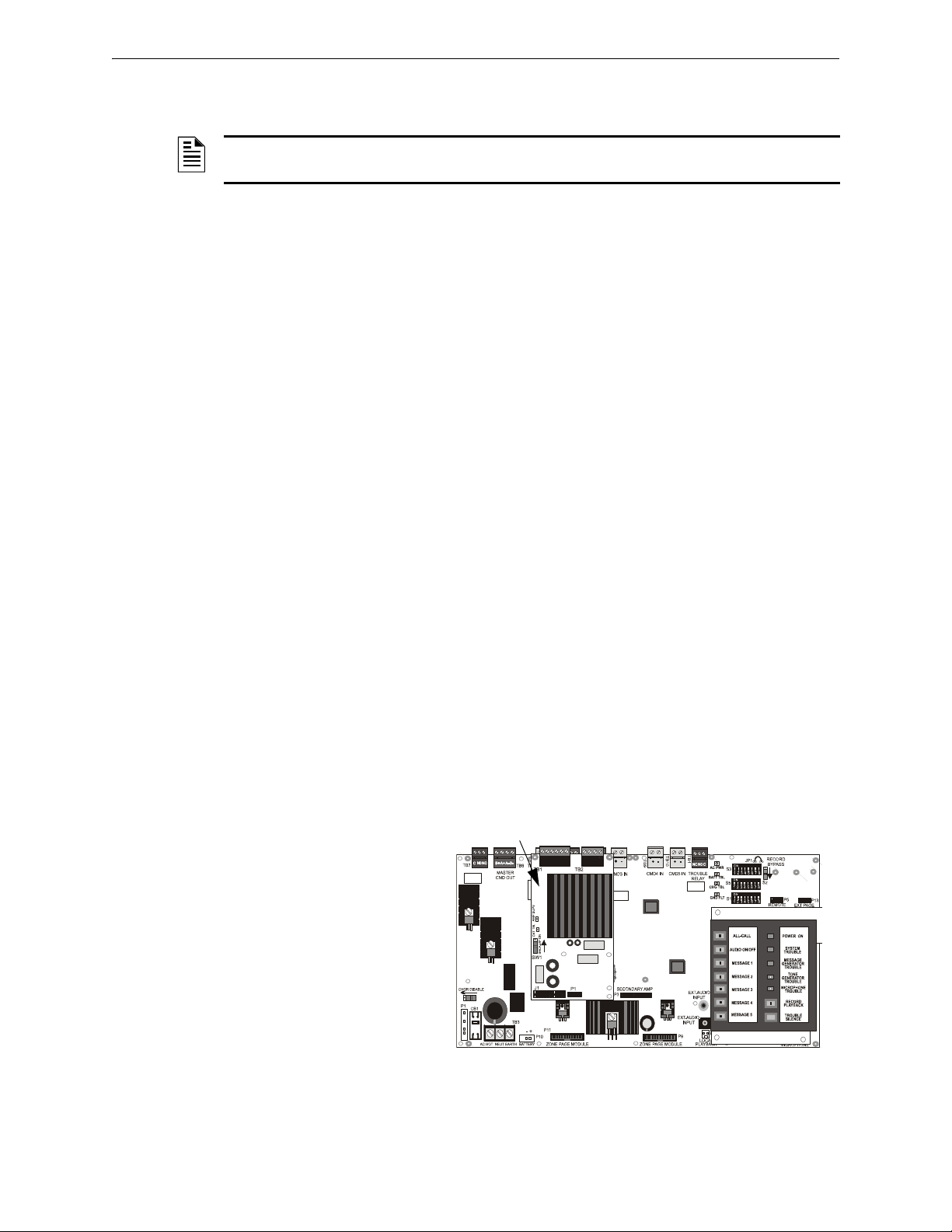
Components Product Description
Figure 1.7 Main Circuit Board
Audio Amplifier
AC25MAST2.wmf
• One Form-C AC Loss Relay. Contacts are rated 2.0 amps @ 30 VDC (resistive) and 0.6 amps
30 VAC (resistive).
NOTE: The Trouble Relay can be programmed to transfer on any trouble condition including AC
Loss or on any trouble condition except AC Loss (see Switch 8 in Table 2.3 on page 34).
FC-MIM Microphone Interface Module or ACC-FFT Fire Fighter Telephone Module
• Connector P5 provides a connection for the optional FC-MIM Microphone Interface Module
which is used to connect the FC-RM Remote Microphone to provide remote microphone
paging capabilities for the ACC-25/50 and ACC-25/50ZS (refer to Remote Microphone
Installation document #51247).
• Connector P5 provides a cable connection to the optional ACC-FFT Fire Fighter Telephone
Module connector J2 for the ACC-25/50ZST Zone System with Telephone. The FC-MIM
module function is incorporated into the ACC-FFT module eliminating the need for the FCMIM (refer to Section “ACC-FFT Fire Fighter Telephone Module (ACC-25/50ZST Only)” on
page 55.
ACC-EPM External Page Module
• Connector P13 provides a connection for the optional ACC-EPM External Page Module which
is used to connect external non-emergency page equipment. The electrically isolated signal
from the external equipment is not supervised by the ACC-25/50 Series panels. Alarm
condition and paging from the ACC-25/50 Series panels have priority and will override all
external page functions. To preserve battery power, non-emergency paging is prohibited
during AC loss conditions.
ACC-ZPMK Zone Page Module (ACC-25/50ZS & ACC-25/50ZST only)
• Connector P11 provides a connection for the ACC-ZPMK Zone Page Module which is used to
annunciate and control the selection of speaker circuits. Refer to Section “ACC-ZPMK Zone
Page Module - ACS Link (ACC-25/50ZS & ACC-25/50ZST)” on page 52.
Local Speaker
• Connector P2 provides a connection for an optional, removable local speaker P/N: FC-LPS, to
be used for reviewing the digital message without broadcasting over the system speakers.
Figure 3.19, “Installation of Speaker Module” on page 60. This option module must be
installed to take advantage of the Playback feature. Note that The FC-LPS must be removed
after use.
1.5 Components
Main Circuit Board
The ACC-25/50 Series main circuit board contains the system's
CPU, tone generators, special
application auxiliary 35 mA
power output, DIP switches for
field programmable features, digital message recorder/generator,
integral microphone input and preamplifier, other primary components and wiring interface
components. One amplifier module is supplied mounted to the
main circuit board. The ACC25/50ZS and ACC-25/50ZST also include one ACC-ZPMK Zone Page Module and one AC-ZSM
Zone Splitter Module (refer to Figure 1.3 on page 18). The ACC-25/50ZST also includes one
Audio Command Center Series Manual — P/N 51889:E1 6/8/2010 27
Page 28
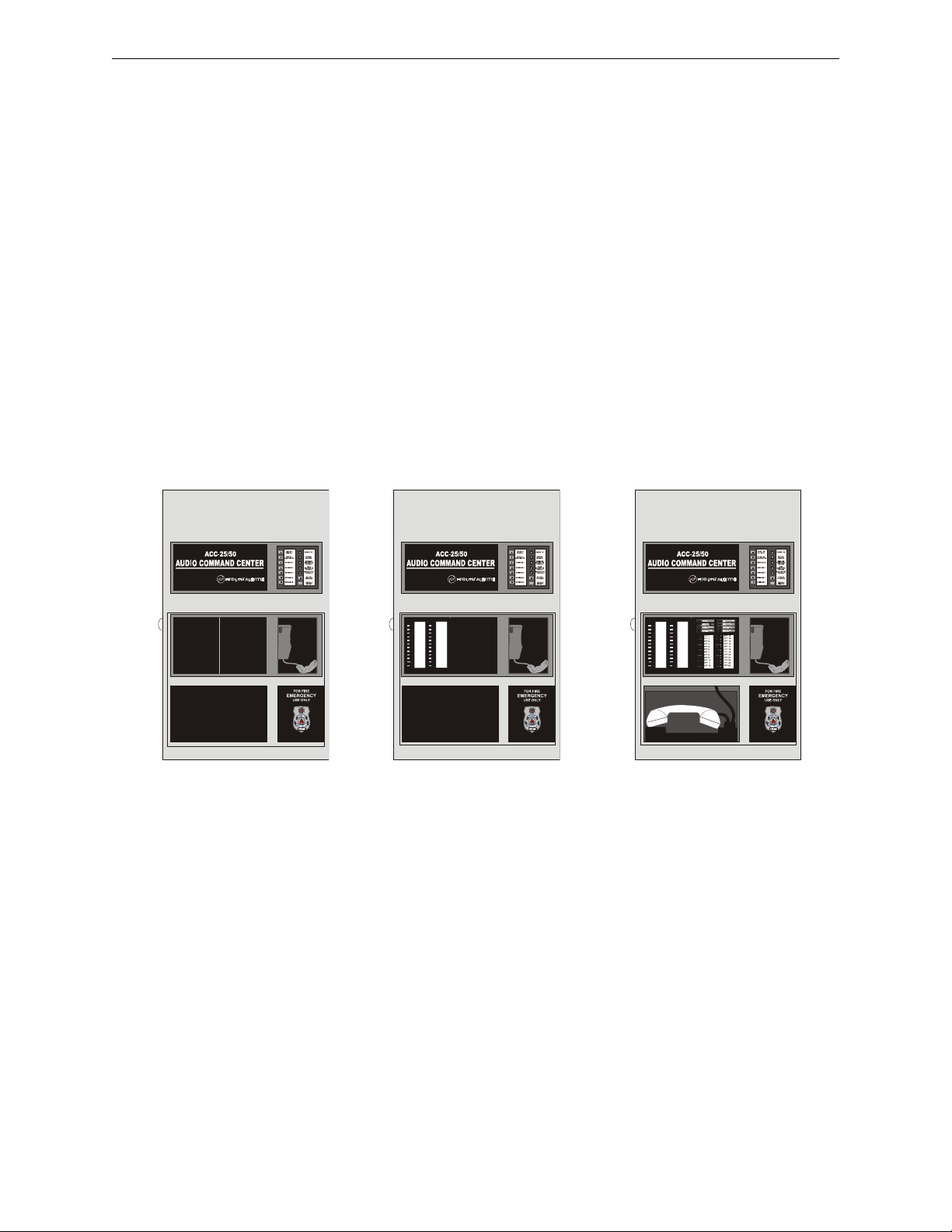
Product Description Components
Figure 1.8 Cabinets
ACC-2550.wmf
ACC-25/50
ACC-25/50ZS
ACC-2550ZS.wmf
ACC-
ACC-25/50ZST
ACC-2550ZST.wmf
ACC-FFT Fire Fighter Telephone Module (refer to Figure 1.4 on page 19). Optional modules can
be plugged in and mounted to the main circuit board. The main circuit board is delivered premounted in the cabinet.
Audio Amplifier Module [ACC-AAM25]
A single Audio Amplifier Module is installed in the ACC-25/50 Series. The amplifier provides 25
watts of power at 25 V
70.7 V
. One fully supervised and power-limited speaker circuit is provided on the amplifier
RMS
. An optional module, P/N: FC-XRM70, converts the 25 V
RMS
output to
RMS
module. The circuit can be wired for Style Y (Class B) or Style Z (Class A) operation.
LEDs are provided to indicate Amplifier Supervision (green indicates amplifier is functional) and
Circuit Trouble (yellow indicates field wiring fault or amplifier fault). The LEDs are only visible
with the panel door open.
Cabinet
The cabinet is red with an attractive navy blue front overlay. A clear window allows viewing of
status LEDs and location of microphone. The backbox measures 26.0" x 15.5" x 4.75" and provides space for two batteries (up to 18 Amp Hours). The ACC-25/50ZS and ACC-25/50ZST cabinets provide a clear window to view the ACC-ZPMK module which is mounted in the center left
portion of the cabinet and the ACC-FFT module which is mounted in the center right portion of the
cabinet.
Batteries
The cabinet provides space for 18 Amp Hour batteries (charged by integral Power Supply/Battery
Charger module).
28 Audio Command Center Series Manual — P/N 51889:E1 6/8/2010
Page 29
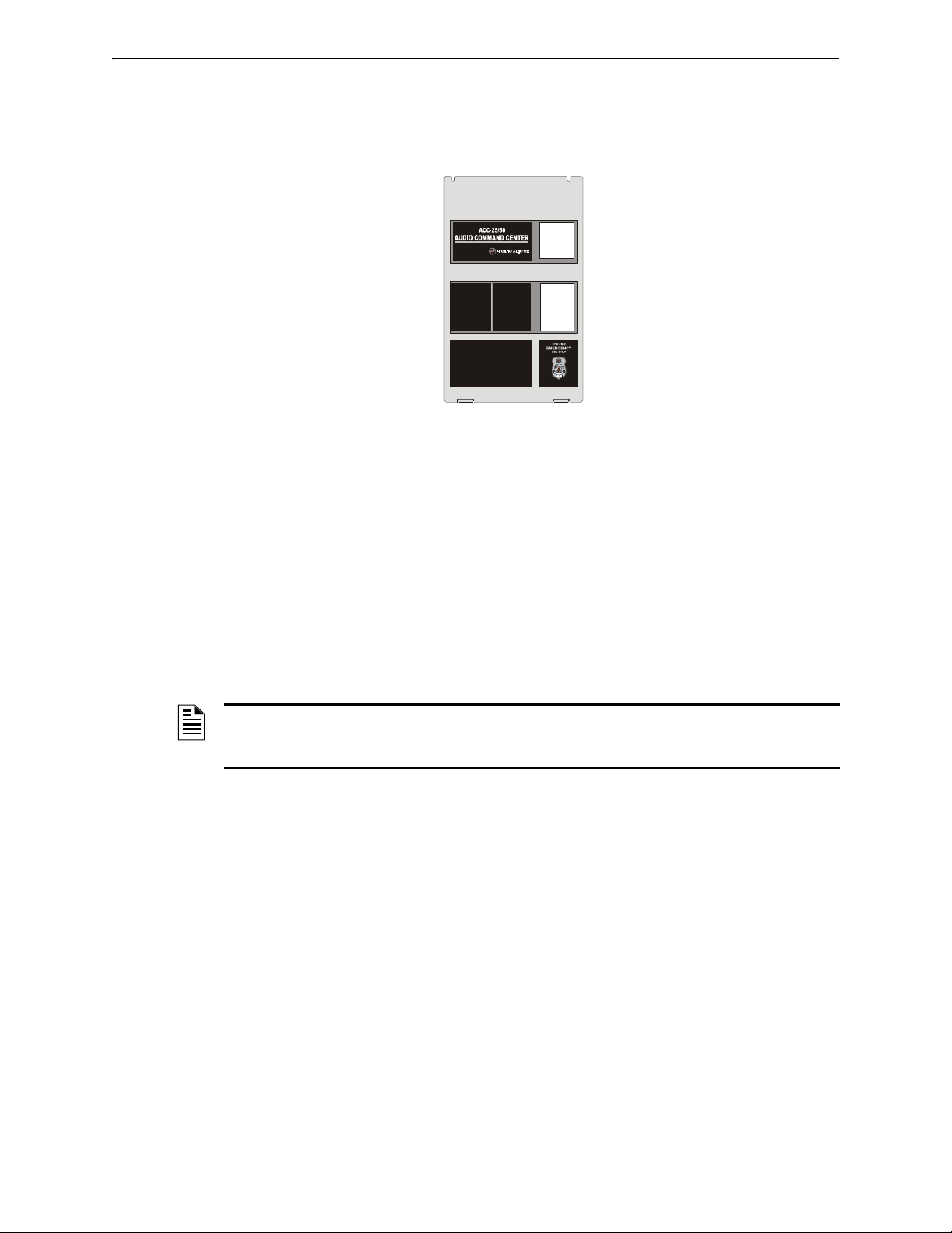
Optional Modules Product Description
Figure 1.9 Dress Panel
ACC-25ZSDP.wmf
Dress Panel
The Dress Panel is supplied standard with the system. It mounts to the cabinet with two supplied
screws. The Dress Panel protects the user from high voltages and circuit boards from accidental
damage. All system LEDs are visible with the Dress Panel installed.
Trim Ring
An optional ACC-TR trim ring is available for semi-flush mounting of the audio panel.
1.6 Optional Modules
ACC-AAM25 Audio Amplifier Module
An optional second identical audio amplifier can be plugged into connector P3 located in the lower
center of the main circuit board in the ACC-25/50 Series. This amplifier also provides 25 watts of
power at 25 V
watt speaker circuits) or it can be used as a backup amplifier. An option module can also be used to
convert the 25 V
NOTE: For ease of access, all wiring should be connected to the terminals on the main circuit
board terminal blocks TB5, TB6, TB9 and TB10 prior to installing the secondary Audio Amplifier
Module.
FC-XRM70 Transformer Module 70.7 V
This optional module plugs into connector P1 of the Audio Amplifier Module and provides conversion from 25 V
FC-LPS Local Playback Speaker
This optional speaker module plugs into connector P2 located in the lower right section of the
ACC-25/50 Series main circuit board. This unit allows reviewing of the digital messages locally
without broadcasting over the system speakers. The optional module must be installed in order to
take advantage of the Playback feature. It may be temporarily used to test recorded messages. A
mounting kit is included for this purpose. The FC-LPS cannot be permanently mounted in the
enclosure and must be removed after use.
and can therefore be used to expand system power to 50 watts (providing dual 25
RMS
output to 70.7 V
RMS
to 70.7 V
RMS
RMS.
RMS
at full rated 25 watts output power.
RMS
FC-RM Remote Microphone
The optional microphone module FC-RM, provides general paging capabilities through the remote
microphone for an audio system. Announcements can be broadcast over the speaker circuits by
depressing the Remote Microphone keyswitch. The FC-MIM Microphone Interface Module must
be installed in the ACC-25/50 or ACC-25/50ZS audio panel for connection to the FC-RM (refer to
the FC-RM Product Installation Document #51247 for installation information).
Audio Command Center Series Manual — P/N 51889:E1 6/8/2010 29
Page 30

Product Description Getting Started
An ACC-25/50ZST does not require an FC-MIM since the function of this module is incorporated
in the ACC-FFT Fire Fighter Telephone module which is included with the ACC-25/50ZST. The
Remote Microphone Module is connected directly to the ACC-FFT Fire Fighter Telephone module
(refer to Section “ACC-FFT Fire Fighter Telephone Module (ACC-25/50ZST Only)” on page 55.
NOTE: Paging operations initiated from within the ACC-25/50 Series main panel will override the
remote microphone.
ACC-EPM External Page Module
This optional module provides an interface to external non-emergency paging equipment. When
activated, a contact closure will switch the external paging equipment into the ACC-25/50 Series
speaker circuits if the circuits have not been activated by the ACC-25/50 Series panels for emergency use. Any emergency/fire activation or local paging will override the ACC-EPM input. Paging from non-emergency equipment is prohibited during AC loss condition to preserve battery
power.
1.7 Getting Started
This section describes the basic guidelines for setting up the various ACC-25/50 Series systems,
assuming that the speaker and FACP cabling has been installed.
1.7.1 ACC-25/50, Requiring up to 50 Watts of Audio Power
• Install backboxes and circuit boards as described in Section 3, ”Installation” on page 42.
• Configure the ACC-25/50 for Single Zone operation, if individual speaker circuit control is not
required, by setting DIP switch S3 switches 1, 2 and 3 on the ACC-MCB mother board. The
factory default setting is Dual Zone output control. Refer to Section 2, ”Field Programming”
on page 32.
• Record any new voice messages as described in Section 4, ”Operating Instructions” on page
63.
1.7.2 ACC-25/50 With ACC-25/50DA(s), Requiring Greater Than 50 Watts of Audio Power
• Connect the Audio Riser and Master Command Bus (for All-Call) cabling between the ACC25/50 and ACC-25/50DA panels. Refer to Section 5, ”Application Examples” on page 80.
• Install backboxes and circuit boards as described in Section 3, ”Installation” on page 42.
• Configure the ACC-25/50 for Single Zone operation using DIP switch S3 switches 1, 2 and 3
on the ACC-MCB motherboard. Refer to Section 2, ”Field Programming” on page 32. The
ACC-25/50DA DIP switches can be left at the default settings.
• Record any new voice messages as described in Section 4, ”Operating Instructions” on page
63.
1.7.3 ACC-25/50ZS & ACC-25/50ZST, Requiring up to 50 Watts of Audio Power
• Install backboxes and circuit boards as described in Section 3, ”Installation” on page 42.
• Configure the ACC-25/50ZS/T for Single Zone operation using DIP switch S3 switches 1, 2
and 3 on the ACC-MCB motherboard. Refer to Section 2, ”Field Programming” on page 32.
• Configure the ACC-ZPM Zone Page Module DIP switch S1 switches 1, 2 and 3 for operation
with the FACP. Refer to Section 2, ”Field Programming” on page 32 and Section 5,
”Application Examples” on page 80.
30 Audio Command Center Series Manual — P/N 51889:E1 6/8/2010
Page 31

Getting Started Product Description
• Record any new voice messages as described in Section 4, ”Operating Instructions” on page
63.
• Program the FACP to operate with the ACC-25/50ZS/T
Enable the ACS serial link or ANN-BUS serial link.
Assign audio zones where applicable (see Section D, ”Programmed Activation by FACP”
on page 105.)
Assign message numbers (1 - 5) where applicable (see Section D, ”Programmed Activation
by FACP” on page 105).
1.7.4 ACC-25/50ZS & ACC-25/50ZST, Requiring Greater Than 50 Watts But Less Than 150 Watts
• Install backboxes and circuit boards as described in Section 3, ”Installation” on page 42.
• Configure the ACC-25/50ZS/T for Single Zone operation using DIP switch S3 switches 1, 2
and 3 on the ACC-MCB motherboard. Refer to Section 2, ”Field Programming” on page 32.
• Configure the ACC-ZPM Zone Page Module DIP switch S1 switches 1, 2 and 3 for operation
with the FACP. Refer to Section 2, ”Field Programming” on page 32 and Section 5,
”Application Examples” on page 80.
• Record any new voice messages as described in Section 4, ”Operating Instructions” on page
63.
• Program the FACP to operate with the ACC-25/50ZS/T
Enable the ACS serial link or ANN-BUS serial link.
Assign audio zones where applicable (see Section D, ”Programmed Activation by FACP”
on page 105).
Assign message numbers (1 - 5) where applicable (refer to Section D, ”Programmed
Activation by FACP” on page 105).
If Remote FFT annunciation is required, assign ACC address as described in Section D,
”Programmed Activation by FACP” on page 105.
• Connect Audio Riser and ACC Control Serial Link cabling between the ACC-25/50ZS(T) and
the ACC-25/50DAZS.
Audio Command Center Series Manual — P/N 51889:E1 6/8/2010 31
Page 32

Section 2: Field Programming
!
Figure 2.1 Field Programming DIP Switches for ACC-25/50, ACC-25/50ZS, & ACC-25/50ZST
AC25switch.wmf
Switches 1 through 7
shown in OFF position
Switch 8 shown
in ON position
The AUDIO•COMMAND•CENTER•25/50, AUDIO•COMMAND•CENTER•25/50ZS, and
AUDIO•COMMAND•CENTER•25/50ZST can be field programmed using option DIP switches
S1, S3 and S5 located in the upper right side of the main circuit board. It is recommended that tone
selection, message repeat cycles and background music options be reviewed and approved by the
local AHJ. The ACC-25/50ZS and ACC-25/50ZST also have a programming DIP switch located
on the ACC-ZPMK Zone Page Module. A Remote Microphone Installed slide switch SW1 is also
located on the ACC-FFT module. Refer to the following illustrations for details on DIP switch
placement in the ON and OFF positions.
CAUTION: STATIC SENSITIVE DEVICES
IN ORDER TO MINIMIZE RISK OF DAMAGE TO ANY CIRCUITS, DO NOT USE CONDUCTIVE TOOLS
WHEN CONFIGURING DIP SWITCHES.
32 Audio Command Center Series Manual — P/N 51889:E1 6/8/2010
Page 33

Field Programming
Figure 2.2 Field Programming DIP Switch for ACC-25/50ZS & ACC-25/50ZST Only
Switch 8 shown
in ON position
Switches 1 through 7
shown in OFF position
ACC-ZPMK
EIA-485 Addressing Switches
ACC-25/50ZS
ac25zswitch.wmf
ACC-FFT
SW1 shown in position when a
Remote Microphone is installed
SW2 shown in position when
a 2-wire connection is made
to the telephone loop.
acc-fftswitch.wmf
The following tables list the ACC-25/50 Series programmable features and the DIP switch settings
required to select a parrticular feature. A detailed description of each feature is presented in the following pages.
S1 DIP Switch ON OFF
1
1
1
2
1
3
1
4
1
5
6 This switch works in conjunction with switches 7 & 8 to determine number of times message will repeat
7 This switch works in conjunction with switches 6 & 8 to determine number of times message will repeat
8 Number of times voice message will repeat:
Enable Temporal Pattern Tone
(switches 2 & 3 must be OFF)
This switch works in conjunction with switch 3 to determine tone to be generated over speakers
Tone transmitted before and after message transmission and as backup tone if message fails:
2 OFF, 3 OFF = Steady Tone
2 OFF, 3 ON -= Slow Whoop Tone (factory default)
2 ON, 3 OFF = Hi-Lo Tone
2 ON, 3 ON = Chime
Enable Tone Transmission Before Message
(factory default)
Enable Tone Transmission After Message Disable Tone Transmission After Message
6 OFF, 7 OFF, 8 OFF = Tone Only, No Voice
6 ON, 7 OFF, 8 OFF = 3
6 OFF, 7 ON, 8 OFF = 4
6 ON, 7 ON, 8 OFF = 6 (factory default)
6 OFF, 7 OFF, 8 ON = 8
6 ON, 7 ON, 8 ON = Infinite (until FACP NAC is reset)
All other settings for switches 6, 7 and 8 are invalid and will default to a message repeat of 3 times
Disable Temporal Pattern Tone (factory default)
(tone generated as selected by switches 2 & 3)
Disable Tone Transmission Before Message
(factory default)
Table 2.1 S1 DIP Switch Settings on ACC-25/50 Series Motherboard (ACC-MCB)
1 Tone selection applies only to Message 1 (Fire Evac). Message 2, Message 3, Message 4, and
Message 5 will output only the message.
Audio Command Center Series Manual — P/N 51889:E1 6/8/2010 33
Page 34

Field Programming
S5 DIP Switch ON OFF
1 not used
2 not used
3 Enable Background Music
4 not used
5 Command Input 1
Activation on Contact Closure
6 Command Input 2
Activation on Contact Closure
7 Record from External Audio Input Source Record from Microphone (factory default)
1, 2
Disable Background Music (factory default)
Command Input 1
Activation on NAC polarity reversal (factory default)
Command Input 2
Activation on NAC polarity reversal (factory default)
3
3
8 Enable Recording of Messages
Record/Playback Key Used for Recording
Disable Recording of Messages
Record/Playback Key Used for Playback (factory default)
Table 2.2 S5 DIP Switch Settings on ACC-25/50 Series Motherboard (ACC-MCB)
1 NFPA 72 requires that speakers used as alarm notification appliances on fire alarm systems not be used
for nonemergency purposes. Consult with the Local AHJ for authorization to use background music.
Only 20 watts of power can be supplied per amplifier if background music is enabled.
2 Background music is not permitted for the ACC-25/50ZS or ACC-25/50ZST, and is prohibited during AC
loss conditions to preserve battery power.
3 When CMD1 and CMD2 are configured for reverse polarity, the NAC cannot be Coded.
S3 DIP Switch ON OFF
1 This switch works in conjunction with switches 2 & 3 to determine Message Control Selection
2 This switch works in conjunction with switches 1 & 3 to determine Message Control Selection
Message Control Selections (DIP switch settings configure message length and CMD to Amplifier control):
1 OFF, 2 OFF, 3 OFF - DUAL ZONE
• 60 second message
3
•CMD1
= message 1 to AAM1
• CMD2 = message 1 to AAM2
1 ON, 2 OFF, 3 OFF - SINGLE ZONE
• 30 second message
• CMD1 = message 1 to AAM1 & AAM2
• CMD2 = message 2 to AAM1 & AAM2
1 OFF, 2 ON, 3 OFF - SINGLE ZONE
3
• 20 second message
• CMD1 = message 1 to AAM1 & AAM2
• CMD2 = message 2 to AAM1 & AAM2
1 ON, 2 ON, 3 OFF - SINGLE ZONE
• 15 second message
• CMD1 = message 1 to AAM1 & AAM2
• CMD2 = message 2 to AAM1 & AAM2
1 ON, 2 OFF, 3 ON - SINGLE ZONE
• 12 second message
• CMD1 = message 1 to AAM1 & AAM2
• CMD2 = message 2 to AAM1 & AAM2
4 This switch works in conjunction with switch 5 to set the AC Loss Delay time
1, 2
4
5, 6, 7
5, 8
5, 8
5, 8
• CMD3 = not used
• CMD4 = not used
• CMD5 = not used
• CMD3 = not used
• CMD4 = not used
• CMD5 = not used
• CMD3 = message 3 to AAM1 & AAM2
• CMD4 = not used
• CMD5 = not used
• CMD3 = message 3 to AAM1 & AAM2
• CMD4 = message 4 to AAM1 & AAM2
• CMD5 = not used
• CMD3 = message 3 to AAM1 & AAM2
• CMD4 = message 4 to AAM1 & AAM2
• CMD5 = message 5 to AAM1 & AAM2
Table 2.3 S3 DIP Switch Settings on ACC-25/50 Series Motherboard (ACC-MCB)
34 Audio Command Center Series Manual — P/N 51889:E1 6/8/2010
Page 35

Field Programming
S3 DIP Switch ON OFF
5 4 OFF and 5 OFF = No AC Loss Delay
4 OFF and 5 ON = 6 Hour Delay
4 ON and 5 OFF = 2 Hour Delay
4 ON and 5 ON = not used (Invalid Setting)
6 Enable All-Call during Remote Mic. Page
7 Enable ACC-25/50ZST operation Enable ACC-25/50 orACC-25/50ZS operation
8 Only AC Loss Relay will transfer upon an AC
loss condition.
8
Disable All-Call during Remote Mic. Page8 - factory default
The CMD1 & Form-C Trouble Relays will track the AC Loss
Relay and transfer upon an AC loss condition.
Table 2.3 S3 DIP Switch Settings on ACC-25/50 Series Motherboard (ACC-MCB)
1 Dual Zone operation directs a single message to either or both amplifier circuits (factory default setting).
2 Dual Zone is not permitted for ACC-25/50ZS or ACC-25/50ZST.
3 CMD1 has the highest priority, CMD5 has the lowest priority.
4 AAM1 refers to the first ACC-AAM25 amplifier circuit and AAM2 refers to the second ACC-AAM25
amplifier circuit.
5 Single Zone operation directs the same message to both amplifier circuits.
6 CMD inputs are not used for activation when ACC-ZPMK is installed with the MS-9200UD, MS-9200UDLS
and MS-9600 Version 2.0 or later. 4.7 K End-of-Line resistors must still be connected across CMD3,
CMD4 and CMD5.
7 When using Distributed Audio Panels, the ACC-25/50 must be configured as single zone.
8 This option defaults to ON for the ACC-25/50ZS and ACC-25/50ZST system.
S1 DIP Switch ON OFF
1 This switch works in conjunction with switches 2 & 3 to configure for operation with specific FACP
2 This switch works in conjunction with switches 1 & 3 to configure for operation with specific FACP
3 1 OFF, 2 OFF, 3 OFF = No FACP, MS-9200UD version 1 or non-ACS FACP connected to ACC-25/50ZS/T-
4 not used (future)
5 not used (must be set to OFF)
6 This switch works in conjunction with switches 7 & 8 to set the number of ACC-25/50DAZS panels connected
7 This switch works in conjunction with switches 6 & 8 to set the number of ACC-25/50DAZS panels connected
8 6 OFF, 7 OFF, 8 OFF = No ACC-25/50DAZS Distributed Audio Panels connected to ACC-25/50ZS/T
(factory default setting)
1 OFF, 2 OFF, 3 ON = MS-5210UD connected to ACC-25/50ZS/T
1 OFF, 2 ON, 3 OFF = MS-9200 connected to ACC-25/50ZS/T
1 OFF, 2 ON, 3 ON = MS-9600 version 1 connected to ACC-25/50ZS/T
1 ON, 2 OFF, 3 OFF = MS-9600 version 2 or higher connected to ACC-25/50ZS/T
1 ON, 2 OFF, 3 ON = MS-9200UDLS and MS-9200UD version 2 or 3 connected to ACC-25/50ZS/T
1 ON, 2 ON, 3 OFF = ANN-BUS Protocol, MS-9600LS, or MS-9200UDLS version 4 or higher, MS-5UD-3, MS-5UD7, MS-10UD-3, and MS-10UD-7 version 2 or higher connected to ACC-25/50ZS/T
1 ON, 2 ON, 3 ON = future use
6 OFF, 7 OFF, 8 ON = 1 ACC-25/50DAZS Distributed Audio Panel connected to ACC-25/50ZS/T
6 OFF, 7 ON, 8 OFF = 2 ACC-25/50DAZS Distributed Audio Panels connected to ACC-25/50ZS/T
6 OFF, 7 ON, 8 ON = 3 ACC-25/50DAZS Distributed Audio Panels connected to ACC-25/50ZS/T
6 ON, 7 OFF, 8 OFF = 4 ACC-25/50DAZS Distributed Audio Panels connected to ACC-25/50ZS/T
6 ON, 7 OFF, 8 ON = 5 ACC-25/50DAZS Distributed Audio Panels connected to ACC-25/50ZS/T
Table 2.4 S1 DIP Switch Settings on ACC-ZPMK (ACC-25/50ZS & ACC-25/50ZST)
Audio Command Center Series Manual — P/N 51889:E1 6/8/2010 35
Page 36

Field Programming S1 DIP Switch Settings on ACC-25/50 Series Motherboard (ACC-MCB)
2.1 S1 DIP Switch Settings on ACC-25/50 Series Motherboard (ACC-MCB)
• Switch 1 - Temporal pattern generated per ANSI S3.41 when Switch 1 is ON and Switches 2
and 3 are OFF
OFF = No temporal pattern - tone generated as selected by Switches 2 and 3 (factory
default setting).
ON = 3 Cycles of Temporal pattern generated on steady tone. Switches 2 and 3 must be in
the OFF position.
• Switches 2 and 3 - used to determine what tone will be transmitted over the speakers before
and after the message is transmitted as well as the backup tone to be transmitted if the digital
voice generator fails.
SWITCH
2
OFF OFF STEADY
OFF ON SLOW WHOOP (factory default)
ON OFF Hi-Lo
ON ON CHIME
SWITCH3TONE TRANSMITTED BEFORE AND AFTER
DIGITAL VOICE MESSAGE
Table 2.5 Switch Settings for Tones
• Switch 4 - used to determine if the tone selected by S1 switches 2 and 3 will be generated
before the message is transmitted:
OFF = No tone before message
ON = Tone before message (factory default setting)
• Switch 5 - used to determine if the tone selected by S1 switches 2 and 3 will be generated after
the message is transmitted:
OFF = No tone after message (factory default setting)
ON = Tone after message
NOTES: Tone Before/After only applies to Message 1 (Fire Evac). Messages 2 through 5 do not
generate a tone before or after the message.
• Switches 6, 7 and 8 - used to determine the number of times the voice message will repeat.
SWITCH
6
OFF OFF OFF Tone Only, No Voice
ON OFF OFF 3
OFF ON OFF 4
ON ON OFF 6 (factory default)
OFF OFF ON 8
ON ON ON INFINITE (until FACP trigger is reset)
All other settings for switches 6, 7 and 8 are invalid and will default to a message repeat of 3 times.
SWITCH
7
SWITCH8NUMBER OF TIMES TO REPEAT DIGITAL VOICE
MESSAGE
1
Table 2.6 Switch Settings for Message Repeat
1 Some jurisdictions require tone evacuate only. This option prevents voice
messages from being generated. Verify with local AHJ if voice message is
allowed and the number of time the message may be repeated.
36 Audio Command Center Series Manual — P/N 51889:E1 6/8/2010
Page 37

S5 DIP Switch Settings on ACC-25/50 Series Motherboard (ACC-MCB) Field Programming
2.2 S5 DIP Switch Settings on ACC-25/50 Series Motherboard (ACC-MCB)
• Switch 1 - not used
• Switch 2 - not used
• Switch 3 - controls whether background music can be played over the speakers from the RCA
Jack Input.
OFF = Background music disabled (factory default setting)
ON = Background music enabled
NOTES:
1. NFPA 72 requires that speakers used as alarm notification appliances on fire alarm systems not
be used for nonemergency purposes. Consult with the Local AHJ for authorization to use
background music with the AUDIO•COMMAND•CENTER•25/50. Only 20 watts of power can be
supplied per amplifier if background music is enabled.
2. The AUDIO•COMMAND•CENTER•25/50ZS and AUDIO•COMMAND•CENTER•25/50ZST do not
support background music.
3. Background music is prohibited during AC loss conditions to preserve battery power.
• Switch 4 - not used
• Switch 5 - used to determine what will activate the Command Input #1.
OFF = Activation on NAC polarity reversal (factory default setting)
ON = Activation on contact closure
• Switch 6 - used to determine what will activate the Command Input #2.
OFF = Activation on NAC polarity reversal (factory default setting)
ON = Activation on contact closure
• Switch 7 - used to determine the source being used to record the digital voice message.
OFF = Record from Microphone (factory default setting)
ON = Record from External Audio Input (RCA Jack or mini PC Jack)
• Switch 8 - used to enable recording of digital voice message.
OFF = Recording not permitted, Record/Playback key used for message playback (factory
default) setting)
ON = Recording permitted, Record/Playback key used to record voice message. Switch
must be restored to default setting upon completion of recording.
2.3 S3 DIP Switch Settings on ACC-25/50 Motherboard (ACCMCB)
• Switches 1, 2 and 3 - used to choose the Message Control Selections which determine how the
CMD inputs will direct the tones/messages to the ACC-AAM25 audio amplifier circuits. The
selections also determine the length of each available message.
Maximum
Switch1Switch2Switch
3
OFF OFF OFF Dual
ON OFF OFF Single
Mode
Zone
Zone
Length of
Each
Message
2
60 sec. Message 1 to
4
30 sec. Message 1 to
1
CMD1
3
AAM1
AAM1 & 2
Message 1 to
Message 2 to
AAM1 & 2
Table 2.7 Switch Settings for Message Control
Audio Command Center Series Manual — P/N 51889:E1 6/8/2010 37
Audio Signal Control
CMD2 CMD3 CMD4 CMD5
not used not used not used
AAM2
not used not used not used
Page 38

Field Programming S2 - Record Bypass Switch on ACC-25/50 Series Motherboard (ACC-MCB)
RECORD
BYPASS
RECORD
BYPASS
2
5
5
0
b
y
p
s
.
w
m
f
Audio Signal Control
CMD2 CMD3 CMD4 CMD5
Message 3 to
AAM1 & 2
Message 3 to
AAM1 & 2
Message 3 to
AAM1 & 2
not used not used
Message 4 to
AAM1 & 2
Message 4 to
AAM1 & 2
Message 5 to
Switch1Switch2Switch
OFF ON OFF Single
ON ON OFF Single
ON OFF ON Single
Mode
3
Zone
Zone
Zone
Maximum
Length of
Each
Message
20 sec. Message 1 to
15 sec.
12 sec.
AAM1 & 2
5
Message 1 to
AAM1 & 2
5
Message 1 to
AAM1 & 2
CMD1
1
Message 2 to
AAM1 & 2
Message 2 to
AAM1 & 2
Message 2 to
AAM1 & 2
Table 2.7 Switch Settings for Message Control
1 CMD1 has the highest priority, CMD5 has the lowest priority.
2 Dual Zone operation directs a single message to either or both amplifier circuits (factory default setting)
3 AAM1 refers to the first ACC-AAM25 amplifier circuit and AAM2 refers to the second ACC-AAM25 amplifier
circuit.
4 Single Zone operation directs the same message to both amplifier circuits.
5 The factory default evacuation message (length = 17 seconds) must be re-recorded to fit into this time slot.
• Switch 4 - used in conjunction with Switch 5 to select AC Loss Delay time.
• Switch 5 - used in conjunction with Switch 4 to select AC Loss Delay time:
4 OFF and 5 OFF = No AC Loss Delay - immediate reporting (factory default)
4 OFF and 5 ON = 6 hour delay
4 ON and 5 OFF = 2 hour delay
4 ON and 5 ON = not used (invalid setting)
• Switch 6 - used for All-Call Paging from Remote Microphone
OFF = disable All-Call paging during page from Remote Microphone (factory default
setting)
ON = enable All-Call paging during page from Remote Microphone
• Switch 7 - used to select audio panel configuration
OFF = ACC-25/50 or ACC-25/50ZS
ON = ACC-25/50ZST
• Switch 8 - used to enable/disable transferring of Trouble Relay/CMD1 trouble contacts during
AC loss
OFF = CMD1 & Trouble Relay contacts track the AC Loss Relay and transfer upon AC
loss condition
ON = Only the AC Loss Relay contacts will transfer upon AC loss condition
not used
AAM1 & 2
2.4 S2 - Record Bypass Switch on ACC-25/50 Series Motherboard (ACC-MCB)
This switch, when placed in the down position, prevents accidental erasure of stored voice messages. See “Record/Playback Button - Record Customized Messages” on page 64 for additional
information.
UP Position = The stored digital voice message may be overwritten with
a new one.
Down Position = The stored digital voice message can not be
overwritten (factory default setting).
38 Audio Command Center Series Manual — P/N 51889:E1 6/8/2010
Page 39

S4 - Battery Charger Switch on ACC-25/50 Series Motherboard Field Programming
a
c
2
5
z
s
s
w
4
.
w
m
f
SW1
REMOTE MIC. INSTALLED
SW2
2 WIRE
4 WIRE
CONNECTION
2.5 S4 - Battery Charger Switch on ACC-25/50 Series Motherboard
This switch controls whether the ACC-25/50 Series will charge the system batteries or if an external battery charger will be used.
Right Position (as shown) = ACC-25/50 Series charges batteries.
Left Position = External battery charger is being used to charge
batteries.
NOTES: The ACC-25/50 Series still indicates battery fault conditions even when internal battery
charger is not used.
2.6 SW1 - Remote Microphone Installed Switch on ACC-FFT
This switch is used to indicate if the remote microphone is connected to the ACC-FFT module.
Right Position = Remote Microphone is not connected
Left Position (as illustrated) = Remote Microphone is connected to ACCFFT (TB1)
NOTES: If SW1 is set to the left position and the Remote Microphone is not installed, a fault
condition will be indicated.
2.7 SW2 - 2 Wire/4 Wire Connection on Telephone Loop
This switch is used to configure 2 Wire (Class B) or 4 Wire (Class A) connections to the telephone
loop.
Up Position (as illustrated) = 2 Wire (Class B) connection to phone loop which
will requires a 4.7K End-of-Line Resistor.
Down Position - 4 Wire (Class A) connection.
2.8 ACC-ZPMK Zone Page Module (ACC-25/50ZS & ACC25/50ZST)
The ACC-ZPMK Zone Page Module has a DIP switch S1 for field programming the ACC-25/50ZS
and ACC-25/50ZST and two rotary address switches S2 and S3 which are used to set the EIA-485
address of the module for communication with an FACP over the ACS link.
Audio Command Center Series Manual — P/N 51889:E1 6/8/2010 39
Page 40

Field Programming ACC-ZPMK Zone Page Module (ACC-25/50ZS & ACC-25/50ZST)
2.8.1 S1 DIP Switch Settings on ACC-ZPMK
• Switches 1, 2 and 3 are used to configure the ACC-25/50ZS/T for operation with a specific
FACP as shown in the following table:
SWITCH1SWITCH2SWITCH
3
OFF OFF OFF MS-9200UD version 1 or non-ACS/ANN-BUS FACP connected
OFF OFF ON ACS Protocol: MS-5210UD
OFF ON OFF ACS Protocol: MS-9200
OFF ON ON ACS Protocol: MS-9600 version 1
ON OFF OFF ACS Protocol: MS-9600 version 2
ON OFF ON ACS Protocol: MS-9200UDLS or MS-9200UD version 2 or 3
ON ON OFF ANN-BUS Protocol:
ON ON ON future use
CONFIGURED FOR OPERATION WITH FOLLOWING FIRE ALARM
CONTROL PANEL
(factory default setting)
MS-9600LS Version 4 or higher
MS-9200UDLS Version 4 or higher
MS-5UD-3, MS-5UD-7, MS-10UD-3 & MS-10UD-7 Version 2 or higher
Table 2.8 FACP Configuration
• Switch 4 - not used (future)
• Switch 5 - not used (must be set to OFF)
• Switches 6, 7 and 8 - used to set the number of ACC-25/50DAZS Distributed Audio Panels
connected to the ACC-25/50ZS or 25/50ZST as shown in the following table:
SWITCH
6
OFF OFF OFF No ACC-25/50DAZS panel connected
OFF OFF ON 1 ACC-25/50DAZS panel connected
OFF ON OFF 2 ACC-25/50DAZS panels connected
OFF ON ON 3 ACC-25/50DAZS panels connected
ON OFF OFF 4 ACC-25/50DAZS panels connected
ON OFF ON 5 ACC-25/50DAZS panels connected
ON ON OFF invalid
ON ON ON invalid
SWITCH
7
SWITCH
8
NUMBER OF ACC-25/50DAZS DISTRIBUTED AUDIO PANELS
CONNECTED TO ACC-25/50ZS or 25/50ZST
Table 2.9 Quantity of ACC-25/50DAZS Panels Connected
40 Audio Command Center Series Manual — P/N 51889:E1 6/8/2010
Page 41

ACC-ZSM Zone Splitter Module (ACC-25/50ZS & ACC-25/50ZST) Field Programming
Figure 2.3 ACC-ZPMK Addressing Switches
a
c
c
z
p
m
a
d
d
.
w
m
f
SW1, which is shown in the AAM 1 & AAM 2
position is set for split amplifier operation.
Note that the factory default setting is AAM1
only for single amplifier operation.
SW2, which is shown in the Class B position,
configures all circuits for Class B (Style Y)
wiring. This is the factory default setting.
a
c
c
z
s
m
s
w
1
.
w
m
f
2.8.2 S2 and S3 Addressing Rotary Switches
Two addressing switches are located at the bottom right of the ACC-ZPMK Zone Page Module.
The switches are used to set the ACS (EIA-485) address of the ACC-ZPMK to allow communication between it and the FACP. This communication link allows the FACP to control speaker zones
under program control.
The ACC-ZPMK must
be set to address 01 to communicate with the FACP. To set the address, use
a small nononductive flat-blade screw driver to turn the switch dial so the arrow points to the correct address number. The factory default setting is S3 = 0 and S2 = 0. The following illustration
shows the switches set for address 01 with S3 (Tens) set to 0 and S2 (Ones) set to 1.
2.9 ACC-ZSM Zone Splitter Module (ACC-25/50ZS & ACC25/50ZST)
Two switches on the ACC-ZSM Zone Splitter Module are used to configure the speaker circuits
connected to it.
• SW1 - used to configure the circuits for split amplifier application. Setting the switch to the
AAM 1 & 2 position directs the audio from Amplifier 1 to the first two Class A circuits or first
four Class B circuits, and the audio from Amplifier 2 to the next two Class A circuits or next
four Class B circuits. Setting the switch to the AAM1 position sends the audio from Amplifier
1 to all circuits.
• SW2 - used to configure all circuits for Class A (Style Z) or Class B (Style Y) operation.
Audio Command Center Series Manual — P/N 51889:E1 6/8/2010 41
Page 42

Section 3: Installation
Figure 3.1 ACC-25/50ZS Cabinet
acc-2550zs.wmf
!
3.1 Mounting Options
All wiring should be in accordance with the National and/or Local codes for fire alarm systems.
The cabinet may be surface mounted. The door is
removable during the installation period by opening and
lifting it off the hinges. The cabinet mounts using two
key slots at the top of the backbox and two additional
0.250" diameter holes located at the bottom.
Carefully unpack the system and check for shipping
damage. Mount the cabinet in a clean, dry, vibration-free
area where extreme temperatures are not encountered.
The area should be readily accessible with sufficient
room to easily install and maintain the panel. Locate the
top of the cabinet approximately five feet above the floor
with the hinge mounting on the right. Determine the
number of conductors required for the devices to be
installed. Sufficient knockouts are provided for wiring
convenience. Select the appropriate knockout(s) and
pull the required conductors into the box. Note that
knockouts are also located on the back of the cabinet.
3.2 Backbox Installation
Surface Mounting
CAUTION: STATIC SENSITIVE COMPONENTS
THE CIRCUIT BOARD CONTAINS STATIC-SENSITIVE COMPONENTS. ALWAYS GROUND
YOURSELF WITH A PROPER WRIST STRAP BEFORE HANDLING ANY BOARDS SO THAT
STATIC CHARGES ARE REMOVED FROM THE BODY. USE STATIC SUPPRESSIVE PACKAGING TO PROTECT ELECTRONIC ASSEMBLIES.
1. Open the door and lift the door off the pin hinges.
2. Remove the main circuit board and transformer from the backbox before installation. Set the
board and transformers aside in a safe, clean place. Avoid static discharge which may damage
static sensitive components on the board.
3. Mark and predrill holes for the top two backbox keyhole mounting bolts using the dimensions
shown.
4. Install two upper fasteners in the wall with the screw heads protruding.
5. Using the upper 'keyholes', mount the backbox over the two screws.
6. Mark and drill the lower two holes.
7. Install the remaining fasteners and tighten all fasteners to complete backbox mounting.
8. Carefully reinstall the main circuit board and transformer, using appropriate precautions to
prevent damage to components due to static discharge.
42 Audio Command Center Series Manual — P/N 51889:E1 6/8/2010
Page 43

Backbox Installation Installation
Top
Right Side
Left Side
Figure 3.2 Cabinet Dimensions & Knockout Locations
Bottom
a
c
c
2
5
e
n
c
.
w
m
f
Hinge
Hinge
Back
of
Box
Back
of
Box
Back
of
Box
Draw wires through the respective knockout locations.
Audio Command Center Series Manual — P/N 51889:E1 6/8/2010 43
Page 44

Installation Backbox Installation
Figure 3.3 ACC-25/50 Series Backbox and Battery Box
a
c
c
2
5
c
a
b
.
w
m
f
Backbox = 4.75” (12.07 cm)
with Door = 4.8” (12.19 cm)
Backbox = 15.5” (39.37 cm)
with Door = 15.78” (40.08 cm)
Backbox = 4.22”
(10.71 cm)
with Door = 4.8”
(12.19 cm)
Backbox = 26.0” (66.04 cm)
with Door = 26.17” (66.48 cm)
44 Audio Command Center Series Manual — P/N 51889:E1 6/8/2010
Page 45

Backbox Installation Installation
!
3.2.1 Transformer Installation
CAUTION: DISCONNECT POWER
BEFORE INSTALLING ANY MODULES OR CABLES, MAKE CERTAIN ALL POWER (AC AND DC)
HAS BEEN REMOVED.
1. Locate two threaded mounting studs and two mounting slots in the bottom left corner of the
backbox (refer to backbox illustration below).
2. Position the Transformer Assembly with the bottom mounting brackets in the mounting slots
and the top brackets on mounting studs, with cable assembly oriented to the top as illustrated
below.
3. Secure the Transformer to the studs with the two supplied nuts. Do not tighten one of the nuts
until the next step.
4. Connect a wire from a solid earth ground to one of the Transformer mounting studs and tighten
the nut. This connection is necessary in order to provide proper lightning and transient
protection for the panel.
5. Plug Transformer cable assembly into connector P1 which is located in the lower left side of
the main circuit board. Note that the Transformer cable connector is keyed to prevent incorrect
connection.
6. Complete the installation by connecting the AC power wires to Hot, Neutral and Earth
terminals of TB3 on the main circuit board.
7. If batteries are being used, connect the batteries (18 AH maximum) to connector P10 located to
the bottom left of the main circuit board.
8. Apply power to the panel.
Audio Command Center Series Manual — P/N 51889:E1 6/8/2010 45
Page 46

Installation Operating Power
!
Backbox
Transformer Mounting Studs
acc25bkb.wmf
Transformer Mounting Slots
Main Circuit Board
Mounting Studs
P1 Connector Transformer
a
c
2
5
x
m
n
t
.
w
m
f
AC Terminal TB3
P10 Connector - Battery
Transformer Assembly
Figure 3.4 Installation of Power Supply Transformer
3.3 Operating Power
46 Audio Command Center Series Manual — P/N 51889:E1 6/8/2010
WARNING: RISK OF EQUIPMENT DAMAGE AND PERSONAL INJURY
SEVERAL DIFFERENT SOURCES OF POWER CAN BE CONNECTED TO THIS PANEL. DISCONNECT ALL SOURCES OF POWER BEFORE SERVICING. THE PANEL AND ASSOCIATED
EQUIPMENT MAY BE DAMAGED BY REMOVING AND/OR INSERTING CARDS, MODULES OR
INTERCONNECTING CABLES WHILE THIS UNIT IS ENERGIZED. BE SURE TO OBSERVE
PROPER GROUNDING AND HANDLING PROCEDURES.
AC Power and Earth Ground Connection
Primary power source for the ACC-25/50, ACC-25/50ZS, and ACC-25/50ZST is 120 VAC, 60 Hz,
1.5 amps. Overcurrent protection for this circuit must comply with Article 760 of the National
Electrical Code (NEC) and/or local codes. Make certain that the AC mains circuit breaker is off
before making any wiring connections between the mains and the panel. Run a pair of wires (with
ground conductor) from the protected premises main breaker box to TB3 of the main circuit board.
Page 47

Operating Power Installation
!
Figure 3.5 Operating Power Connections
a
c
2
5
p
o
w
r
.
w
m
f
ACC-ZSM Mounting Bracket
VAC
Hot (black)
Neutral (white)
Ground (green)
Connect Earth Ground
wire to ground stud
black red
two 12 VDC
batteries
Use 14 AWG (1.6 mm O.D.) or heavier gauge wire with 600V insulation. No other equipment may
be connected to this circuit and it may not contain any power disconnect devices. A separate Earth
Ground connection must be made to ensure proper panel operation and lightning and transient protection. Connect the Earth Ground wire (minimum 14 AWG) to one of the transformer mounting
studs. Do not use conduit for the Earth Ground connection since this does not provide reliable protection.
Secondary Power Source (Batteries)
WARNING: RISK OF PERSONAL INJURY
BATTERY CONTAINS SULFURIC ACID WHICH CAN CAUSE SEVERE BURNS TO THE SKIN
AND EYES AND CAN DESTROY FABRICS. IF CONTACT IS MADE WITH SULFURIC ACID,
IMMEDIATELY FLUSH THE SKIN OR EYES WITH WATER FOR 15 MINUTES AND SEEK IMMEDIATE MEDICAL ATTENTION.
Observe polarity when connecting the batteries. Connect the battery cable to P10 on the main circuit board, using the plug-in connector and cable provided. The battery charger is current-limited
and capable of recharging sealed lead acid type batteries (See Figure 3.5 for battery orientation).
The charger shuts off when the system is in alarm. page 98 for calculation of the correct battery rating.
Audio Command Center Series Manual — P/N 51889:E1 6/8/2010 47
Page 48

Installation Auxiliary DC Power Output Connections
Special Application Power (35 mA @ 24 VDC) is nonresettable power suitable for
powering control modules and End-of Line Power supervision relays. See Device
Compatibility Document for compatible devices.
Figure 3.6 Auxiliary Power Connection
2
5
5
0
t
b
4
.
w
m
f
3.4 Auxiliary DC Power Output Connections
The Special Application Auxiliary DC power output is power-limited.
3.5 Input/Initiating Circuits
The ACC-25/50 Series has five Command Input circuits, which are used to activate the panel
amplifiers which, in turn, transmit an audio signal over the system speakers. All field wiring for
the circuits is power-limited and supervised for opens and ground faults. Note that zero impedance
to ground will cause a ground fault.
CMD1 and CMD2 Command Input circuits can be independently field programmed to be triggered
by a contact closure or by the reverse polarity of a Notification Appliance Circuit.
IMPORTANT! When CMD1 and CMD2 are configured for reverse polarity, the NAC cannot
be
Coded.
Input and output terminals are provided for CMD1 and CMD2 to allow placement of the ACC25/50 Series anywhere along a Notification Appliance Circuit allowing nondedicated use of host
FACP NAC for triggering. CMD1 has relay contacts (maximum current 2.0 amps) before the out
terminals which will open the outgoing NAC circuit during a ACC-25/50 trouble condition (AC
loss is programmable as described for switch 8 in Table 2.3 on page 34). This causes a NAC trou-
48 Audio Command Center Series Manual — P/N 51889:E1 6/8/2010
Page 49

Output Circuits Installation
Figure 3.7 Command Input Circuits
Style Z (Class A)
FACP EOL Resistor
(for Style Y - Class B only)
Polarized Strobe
Polarized Strobe
Polarized Strobe
Polarized Strobe
Polarized Strobe
Polarized Strobe
NAC reverse polarity trigger
(alarm polarity shown)
Class B (Style B) Contact Closure trigger input. (4.7K,
1/4 watt EOL Resistors P/N: 27072)
AUDIO•COMMAND•CENTER•25/50 Series Voice Evacuation
Control Panel
a
c
2
5
t
b
5
.
w
m
f
alarm polarities shown
Host FACP
NAC
ble at the host FACP. Note that CMD1 and CMD2 configurations can be independently set so that
both circuits are triggered by the same type of input or by different types of inputs (see Figure 3.7
on page 49).
3.6 Output Circuits
CMD3, CMD4 and CMD5 Command Input circuits are triggered by a contact closure only. Each
Command input will activate various messages and amplifiers depending on the Message Control
selection configured by S3 DIP switches 1, 2 and 3 (see Table 2.7 on page 37).
3.6.1 Master Command Bus Output
The Master Command Output is a 24 VDC reverse polarity output (TB6) which can be used as an
All-Call trigger for the Audio Command Center Distributed Audio panel. Refer to the ACC-
25/50DA manual, Document #52265 for additional information. The Master Command Output
may activate during emergency or nonemergency paging. See “S3 DIP Switch Settings on ACC25/50 Motherboard (ACC-MCB)” on page 37.
When connecting the Master Command Output of the main panel to the Master Command Inputs of
other devices, the wiring must be supervised by a 4.7K EOL resistor connected across the out terminals of Master Command Input #1 on the last panel for Style Y (Class B) installations. For Style
Z (Class A) installations, connect the return wires to the A+ and A- terminals on TB6.
Audio Command Center Series Manual — P/N 51889:E1 6/8/2010 49
Page 50

Installation Output Circuits
Figure 3.8 Example 1 - Activating Multiple ACC-25/50DAs with Master CMD Output Bus
4.7K
P/N: 27072
(Alarm polarities shown)
Activated when the AllCall button, remote
microphone key or
External Page Module
is pressed (single zone
configuration only)
ACC-25/50DA
ACC-25/50 Series
ac25out.wmf
Master CMD
Output Bus
ACC-25/50DA
Master CMD
Bus In/Out
Master CMD
Bus In/Out
Style Z (Class A)
Figure 3.9 Example 2 - Activating MR-101C (or MR-201C) with Master CMD Output Bus
Relays may be used to activate an FACP initiating circuit.
CAUTION! All wiring to relay must be in same room within
20 feet of FACP and in conduit.
Relay Energized LED
SPDT Contacts
10 amps @ 115 VAC
a
c
2
5
m
r
1
0
.
w
m
f
Master ACC-25/50 Series
Activated when the All-Call button,
remote microphone key or External
Page Module is pressed (single
zone configuration only)
In Example 1 illustrated below, the ACC-25/50 Series panel will trigger the ACC-25/50DA(s)
when All-Call is activated for emergency or general paging.
The maximum line resistance from the main ACC-25/50 Series to the last ACC-25/50DA is 200
ohms (100 ohms per conductor).
The MR-101C (one Form-C relay) and MR-201C (two Form-C relays), which are manufactured by
Air Products and Controls, include an enclosure.
50 Audio Command Center Series Manual — P/N 51889:E1 6/8/2010
Page 51

Output Circuits Installation
Figure 3.10 Trouble Relay
TB1
2
5
5
0
a
c
r
l
.
w
m
f
Shown in energized,
nontrouble condition
Note: Relay connections may be power-limited or
nonpower-limited, provided that 0.25” spacing is
maintained between conductors of power-limited
and nonpower-limited circuits. Refer to Section “UL
Power-limited Wiring Requirements” on page 56.
Figure 3.11 AC Power Loss Relay
TB7
2550acrl.wmf
Shown in energized,
normal AC Power condition
Note: Relay connections may be power-limited
or nonpower-limited, provided that 0.25”
spacing is maintained between conductors of
power-limited and nonpower-limited circuits.
Refer to Section “UL Power-limited Wiring
Requirements” on page 56.
!
3.6.2 Trouble Relay - TB1
The main circuit board provides a Form-C Trouble relay, for independent monitoring, rated for 2.0
amps @ 30 VDC (resistive) and 0.6 amp @ 30 VAC (resistive). This relay is ‘fail safe’, meaning
that it is normally energized. Should system power shut off, this relay will deenergize, transferring
its contacts. The Trouble Relay can be programmed to track the AC Loss Relay and transfer on AC
loss conditions or ignore AC loss conditions (refer to switch 8 in Table 2.3 on page 34).
3.6.3 AC Power Loss Relay - TB7
The main circuit board provides a Form-C AC Power Loss relay rated for 2.0 amps @ 30 VDC
(resistive) and 0.6 amps @ 30 VAC (resistive).
3.6.4 Notification Appliance Circuit (Speakers)
Each Amplifier Module provides one Notification Appliance Circuit for speakers. The circuit can
be wired Style Y (Class B) or Style Z (Class A). Each supervised and power-limited circuit is capable of 25 watts of power. The maximum total capacitance for each speaker circuit cannot exceed
250 uF. Refer to the Fire•Lite Device Compatibility Document for a listing of compatible speakers.
CAUTION: OBSERVE POLARITY
MATCH PROPER POLARITY CONNECTIONS TO FIELD WIRING AND SPEAKERS. POLARITY
SHOWN IS IN THE STANDBY AND ALARM CONDITIONS.
Audio Command Center Series Manual — P/N 51889:E1 6/8/2010 51
Page 52

Installation Output Circuits
Figure 3.12 Speaker Circuit Connections
Style Z (Class A) Circuit
ELR Resistor required for
Style Y - Class B only
4.75K, 1 watt, P/N:75470
Shield
2
5
5
0
c
k
t
1
.
w
m
f
Shielded cable is not required, however, shielded cable will reduce RFI/EMI emissions and susceptibility. For additional information, refer to “Wiring Requirements” on page 104.
3.6.5 ACC-ZPMK Zone Page Module - ACS Link (ACC-25/50ZS & ACC-25/50ZST)
The ACC-ZPMK Zone Page Module provides push button control and annunciation of the speaker
circuits connected to the ACC-ZSM Zone Splitter Module. The LEDs associated with each speaker
circuit will display the circuit status, indicating when the circuit has been manually activated or disabled as well as circuit troubles. In addition, they will indicate speaker activation under FACP program control. In order to provide program control, an ACS (EIA-485) link must be established
between the ACC-ZPMK and FACP. This is accomplished by wiring TB1 on the Zone Page Mod-
52 Audio Command Center Series Manual — P/N 51889:E1 6/8/2010
Page 53

Output Circuits Installation
ACC-ZPMK
TB1
TB2
To FACP
ACS Terminal
Address 01
Set S2 = 1
Set S3 = 0
To Other
ACS
Devices
Located
Down
Stream
+
+
--
1 2 3 4
Figure 3.13 Zone Page Module
Ferrite Bead
Ferrite Bead in open position
Ferrite Bead in closed position
Large gauge wire should be looped
through bead at least once as
illustrated. Smaller gauge wire can
be looped more often
+
+
-
-
Style Z (Class A) return from last
ACC-25/50DAZS, if installed.
To ACC-25/50DAZS
panel(s) if installed
DIP Switches 6, 7 and 8 are used to
set the number of ACC-25/50DAZS
panels installed [see Section 2.8,
”ACC-ZPMK Zone Page Module
(ACC-25/50ZS & ACC-25/50ZST)” on
page 39]
FACP
Zone 1
Zone 2
Zone 3
Zone 4
Zone 5
Zone 6
Zone 7
Zone 8
Zone 9
Zone 10
Zone 11
Zone 12
ACC
Zone 13
Zone 14
Zone 15
Zone 16
Zone 17
Zone 18
Zone 19
Zone 20
Zone 21
Zone 22
Zone 23
Zone 24
a
c
c
z
p
m
b
r
d
.
w
m
f
a
c
c
z
p
m
k
y
p
.
w
m
f
2
5
5
0
f
e
r
r
.
w
m
f
ule to the ACS terminal on the FACP. Circuit wiring requires a ferrite bead as illustrated in Figure
3.13.
Note that the ACC-ZPMK must be set to address 01 in order to communicate with the FACP.
Audio Command Center Series Manual — P/N 51889:E1 6/8/2010 53
Page 54

Installation Output Circuits
Class A (Style Z) Wiring
Jumper all unused circuits (+ to + and - to -)
when configured for Class A wiring.
Class B (Style Y) Wiring
ELR Resistor required for
Style Y (Class B) only
4.75K, 1 watt, P/N:75470
To TB1 pins 3 & 4 on
ACC-AAM25 #1
To TB1 pins 3 & 4
on ACC-AAM25 #2
Dummy load all unused
circuits with 4.75K, 1
watt resistor, P/N: 27589
when configured for
Class B wiring.
SW1 shown set for
Split Amplifier
operation, where TB1
& TB2 are driven by
ACC-AAM25 #1 and
TB5 & TB6 are driven
by ACC-AAM25 #2.
SW2 shown set
for Class B wiring
4.75K, 1 watt resistor,
P/N: 27589 required
when ACC-AAM25 is
connected to terminals.
a
c
c
z
s
m
w
i
r
e
.
w
m
f
Figure 3.14 Zone Splitter Module
CAUTION! For correct supervision in the split amplifier configuration, ACC-ZSM TB2 pins 1 & 2
must connect to ACC-AAM25 #1 and ACC-ZSM TB9 pins 1 & 2 must connect to ACC-AAM25 #2
a
c
c
z
s
m
w
i
r
e
.
w
m
f
3.6.6 ACC-ZSM Zone Splitter Module (ACC-25/50ZS & ACC25/50ZST)
The ACC-ZSM Zone Splitter Module provides connections for four Style Z (Class A) or eight
Style Y (Class B) speaker circuits. Circuits are configured by setting switch SW2 on the ACCZSM to the Class A or Class B position (refer to Section “ACC-ZSM Zone Splitter Module
(ACC-25/50ZS & ACC-25/50ZST)” on page 41).
54 Audio Command Center Series Manual — P/N 51889:E1 6/8/2010
Page 55

Output Circuits Installation
SW1
J1
TB1TB2TB3
FFT 1
FFT 2
FFT 3
FFT 4
FFT 5
FFT 6
FFT 7
FFT 8
FFT 9
FFT 10
FFT 11
FFT 12
FFT 13
FFT 14
FFT 15
FFT 16
FFT 17
FFT 18
FFT 19
FFT 20
FFT 21
FFT 22
FFT 23
FFT 24
1 2 3 4 5 6
1 2 3 4 5 6 1 2
LED 2
LED 1
P1
TB1
TB2
3
2
1
3
2
1
TB1
TB2321123
TB1
TB2
3
2
1
1
2
3
J2
RPJ-F
4.7K, ½ watt ELR
P/N 27072 (install on
last device for Style Y
[Class B] circuit only)
Style Z (Class A) return
FC-RM
ACC-FFT
FPJ-F
Figure 3.15 ACC-FFT Fire Fighter Telephone Module
a
c
c
-
f
f
t
w
i
r
e
.
w
m
f
minimonitor
module
minimonitor
module
to SLC
to SLC
4.7K, ½ watt ELR
P/N 27072 (install on
last device)
FHS-F
+ Keyswitch
- Keyswitch
+ Audio
- Audio
PWR
GRND
+ Audio
- Audio
earth
violet
yellow
red black
violet
yellow
black
red
shield
3.6.7 ACC-FFT Fire Fighter Telephone Module (ACC-25/50ZST Only)
The ACC-FFT provides connection for a single Style Y (Class B) or Style Z (Class A) telephone
audio circuit. In addition, a terminal block is provided for connection to an FC-RM Remote Microphone module. A terminal block is also provided for connection to the Keyswitch on an RPJ-F
Remote Page Jack which allows remote paging by a Remote Telephone (FHS-F). If an addressable
FACP is installed, a monitor module can be used to monitor the connection of Fire-Fighter Telephones (FHS-F) into the FPJ-F or RPJ-F, which is then displayed on the ACC-FFT keypad.
Audio Command Center Series Manual — P/N 51889:E1 6/8/2010 55
Page 56

Installation UL Power-limited Wiring Requirements
Figure 3.16 Typical Wiring Diagram for UL Power-limited Requirements
Nonpower-limited Circuit
Power-limited Circuit
Nonpower-limited Circuit
AC Power
Nonpower-limited
a
c
2
5
u
l
p
w
.
w
m
f
3.7 UL Power-limited Wiring Requirements
Power-limited and nonpower-limited circuit wiring must remain separated in the cabinet. All
power-limited circuit wiring must remain at least 0.25" away from any nonpower-limited circuit
wiring. Furthermore, all power-limited and nonpower-limited circuit wiring must enter and exit the
cabinet through different knockouts and/or conduits. A typical wiring diagram for the
AUDIO•COMMAND•CENTER•25/50 with two speaker circuits is shown below.
56 Audio Command Center Series Manual — P/N 51889:E1 6/8/2010
Page 57

Installation of Option Modules Installation
!
3.8 Installation of Option Modules
3.8.1 Audio Amplifier Module (ACC-AAM25)
The optional audio amplifier module is identical to the module provided with the factory standard
panel configuration. It can be used to provide a second 25 watt speaker circuit, increasing the total
ACC-25/50 power to 50 watts, or it can be used as a backup amplifier. LEDs on the amplifier module are for Amp Supervision (green - indicates amp functional) and Circuit Trouble (yellow - indicates wiring fault or amplifier fail). Connector J1 of the audio amplifier module plugs into
connector P3 located at the bottom center of the main circuit board.
CAUTION: DISCONNECT POWER
BEFORE INSTALLING ANY MODULES OR CABLES, MAKE CERTAIN ALL POWER (AC AND DC)
HAS BEEN REMOVED AND BE SURE TO OBSERVE PROPER GROUNDING AND HANDLING
PROCEDURES.
1. For ease of access, all wiring should be connected to the terminals on the main circuit board
terminal blocks TB1, TB9 and TB10 prior to installing the secondary Audio Amplifier
Module.
2. Remove mounting screw shown, from the main circuit board, and save (refer to illustration
below).
3. Install one supplied metal standoff in location from which mounting screw was removed in
Step 2.
4. Install the Audio Amplifier Module by carefully aligning the amplifier's J1 connector with the
P3 connector on the main circuit board. Press the Module securely into place making certain
not to bend or break any connector pins.
5. Secure the Audio Amplifier Module with the supplied screws plus the screw removed in Step
2. It is important to secure the module with the metal screws in order to help protect against
electrical transients.
6. Configure the Audio Amplifier for primary or backup amplifier operation by setting switch S1
on the amplifier:
(1) Position switch S1 in the DOWN position for primary operation which adds the new
amplifier's 25 watts to total system power (50 watts total).
(2) Position switch S1 in the UP 'Backup On' position to configure the amplifier as a
backup in the event the primary amplifier fails. Also for ACC-25/50ZS & ACC25/50ZST: position switch SW1 on the ACC-ZSM board to the AAM1 position for single
amplifier circuit operation.
7. Check to make certain the factory installed jumpers are in place on P1 of the Audio Amplifier
Module(s). Do not remove unless installing the FC-XRM70 Transformer Module. See
Figure 3.18 on page 59 for more information.
Audio Command Center Series Manual — P/N 51889:E1 6/8/2010 57
Page 58

Installation Installation of Option Modules
Figure 3.17 Installation of Optional Audio Amplifier
ACC-AAM25 Audio Amplifier
Module - to connector P3 of
the main circuit board
(Steps 4 & 5)
Remove mounting screw and
install supplied Metal Standoff
(Steps 2, 3, & 5)
ACC-AAM25 Audio
Amplifier Module factory supplied on
connector P4 of the
main circuit board
Factory installed
metal standoff
(Steps 2 & 5)
Switch S1 Backup select
(Step 6)
Factory installed metal standoff (Steps 2 & 5)
Amplifier J1 to main circuit board P3 (Step 4)
Circuit
Trouble
Amp
Supervision
Do not remove jumpers
unless installing FCXRM70 Module (Step 7)
a
c
c
2
5
m
t
3
.
w
m
f
!
8. Connect field wiring to newly installed amplifier. Refer to Figure 3.12 on page 52 for
illustration of speaker connections if amplifier is being used to expand system power to 50
watts (i.e. providing dual 25 watt speaker circuits). Figure 5.2 on page 82 for illustration of
connections if amplifier is being used as a backup.
3.8.2 70.7 V
The 70.7 V
where 70.7 V
supervised during standby, alarm and while background music is playing when transformer is
installed. Transformer connector J1 connects to amplifier connector P1.
CAUTION: DISCONNECT POWER
BEFORE INSTALLING ANY MODULES, MAKE CERTAIN ALL POWER (AC AND DC) HAS BEEN
REMOVED.
1. Carefully remove the ACC-AAM25 Audio Amplifier Module(s) from the main circuit board.
Figure 3.17 on page 58 for installation procedures and reverse the steps.
2. Install the three standoffs supplied with the FC-XRM70 Module by inserting each supplied
screw into the three holes on the solder side of the ACC-AAM25 Audio Amplifier Module(s).
Secure each standoff in place with the screws. Refer to Figure 3.18 for the location of the
mounting holes.
3. Reinstall the Audio Amplifier Module(s) following the procedure accompanying Figure 3.17.
4. Remove the two factory installed jumpers from connector P1 of the Audio Amplifier
Module(s). Refer to the illustration in Figure 3.18.
5. Carefully align the J1 connector on the FC-XRM70 Transformer Module(s) with the P1
connector on the Audio Amplifier Module and press securely into place. Make certain the pins
are properly aligned to prevent bending or breaking of pins.
Transformer Module (FC-XRM70)
RMS
Transformer Module can be used to convert the 25 V
RMS
speakers already exist or are to be installed. Speaker wiring continues to be
RMS
amplifiers for installations
RMS
58 Audio Command Center Series Manual — P/N 51889:E1 6/8/2010
Page 59

Installation of Option Modules Installation
Figure 3.18 70.7 V
RMS
Transformer Module Installation
Position standoff
(Step 2)
Install standoff
(Step 2)
Solder side
Secure with
screw (Step 2)
ACC-AAM25
Audio Amplifier
Module
Two Factory Installed Jumpers on P1 of Each
Amplifier Module Must be Removed to Install
the 70.7 V
RMS
Transformer (Step 4)
Install Standoff in
Mounting hole
(Step 2)
Install Standoffs in
Mounting holes (Step 2)
FC-XRM70
Transformer Module
a
c
2
5
x
f
m
n
.
w
m
f
ACC-AAM25 Audio
Amplifier Module
2
5
5
0
s
n
t
3
.
w
m
f
6. Secure the FC-XRM70 Transformer Module(s) to the Audio Amplifier Module(s) with the
supplied screws.
3.8.3 Local Playback Speaker Module (FC-LPS)
The Local Playback Speaker Module can be used to monitor the recorded digital message without
transmitting the message over the system speakers. The speaker module plugs into P2 of the main
circuit board. This optional module is necessary to take advantage of the Playback feature.
Audio Command Center Series Manual — P/N 51889:E1 6/8/2010 59
The Speaker Module is connected by simply plugging the module connector into P2 of the main
circuit board. The Speaker Module may be temporarily
supplied mounting hardware.
1. Remove the main circuit board mounting screw located on the bottom center of the board.
2. Install the supplied metal standoff in the mounting hole just vacated in Step 1 and screw
3. Position the FC-LPS mounting bracket hole over the standoff and secure with screw removed
4. Plug the FC-LPS Local Playback Speaker Module's polarized connector into connector P2 on
installed during the test period by using the
Refer to the illustration below.
standoff into place.
in Step 1.
the main circuit board. P2 is located on the bottom right of the main circuit board near the
Control/Indicator panel.
Page 60

Installation Installation of Option Modules
Plug Speaker Module Cable
into connector P2 (Step 4)
Remove mounting screw from main
circuit board and install metal
standoff (Steps 1 and 2)
Install FC-LPS Speaker
Module on metal
standoff (Step 3)
a
c
2
5
s
p
k
r
2
.
w
m
f
(Step 2) Install one metal
standoff by screwing into place
Main Circuit Board Main Circuit Board Main Circuit Board
Speaker
Module
2
5
5
0
s
p
k
s
.
w
m
f
(Step 1) Remove the mounting screw
from bottom center of main circuit board
(Step 3) Install Speaker Module
and secure with screw
Figure 3.19 Installation of Speaker Module
!
5. When testing is completed, remove the FC-LPS and standoff and reinstall the screw. The
FC-LPS is not approved for permanent connection.
3.8.4 ACC-EPM External Page Module
The ACC-EPM External Page Module can be used to interface an existing nonemergency page system with the ACC-25/50 Series panels. The connection is not supervised and the external page system will have the lowest priority which allows the ACC-25/50 Series to override all non-fire
paging. Paging from non-emergency equipment is prohibited during AC loss conditions to preserve battery power.
The External Page Module is installed by plugging the module into connector P13 which is located
60 Audio Command Center Series Manual — P/N 51889:E1 6/8/2010
in the top right corner of the main circuit board.
CAUTION: DISCONNECT POWER
BEFORE INSTALLING ANY MODULES, MAKE CERTAIN ALL POWER (AC AND DC) HAS BEEN
REMOVED.
1. Carefully align the J1 connector on the ACC-EPM module with the P13 connector on the main
circuit board and press securely into place. Make certain the pins are properly aligned to
prevent bending or breaking of pins.
2. Secure the ACC-EPM module to the main circuit board standoff with the supplied screw.
3. Wire the external paging system to Terminal TB1 on the ACC-EPM. Refer to the
documentation supplied with the external paging system to ensure proper connection.
Page 61

Installation of Option Modules Installation
Figure 3.20 ACC-EPM External Page Module Installation
P13 Connector on
main circuit board
J1 connector
on ACC-EPM
ACC-25/50 Series Main Circuit Board
From external page system audio (600, 700 mV
RMS
)
Contact closure from external page system
1 2 3 4
a
c
c
e
p
m
i
n
s
t
.
w
m
f
4. Test the system to ensure proper operation.
Audio Command Center Series Manual — P/N 51889:E1 6/8/2010 61
Page 62

Notes
62 Audio Command Center Series Manual — P/N 51889:E1 6/8/2010
Page 63

Section 4: Operating Instructions
Figure 4.1 Controls and Indicators
Single Zone Operation
a
c
c
2
5
k
y
b
l
n
k
.
w
m
f
ALL-CALL
AUDIO ON/OFF
MESSAGE 1
MESSAGE 2
MESSAGE 3
MESSAGE 4
MESSAGE 5
POWER ON
SYSTEM
TROUBLE
MESSAGE
TROUBLE
GENERATOR
TONE
GENERATOR
TROUBLE
RECORD
PLAYBACK
TROUBLE
SILENCE
MICROPHONE
TROUBLE
Figure 4.2 Controls and Indicators
Dual Zone Operation
a
c
c
2
5
k
y
b
l
n
k
.
w
m
f
ZONE 1
ZONE 2
MESSAGE 1
POWER ON
SYSTEM
TROUBLE
MESSAGE
TROUBLE
GENERATOR
TONE
GENERATOR
TROUBLE
RECORD
PLAYBACK
TROUBLE
SILENCE
MICROPHONE
TROUBLE
4.1 Switch Functions
4.1.1 Single Zone Operation (ACC-25/50, ACC-25/50ZS, ACC-25/50ZST)
Figure 4.1 depicts Single Zone operation with the
maximum capacity of five messages. Single Zone
may be configured for two to five message control
(refer to Section 2, ”Field Programming” on page
32).
• ALL-CALL:
– used to select All Call function when ACC-
25/50 Series is programmed for Single Zone
operation. Selecting this button also activates
the Master Command Bus, which is used to
trigger Distributed Audio Panels. Single Zone
operation directs the same message to all
speaker circuits (S3 DIP switches 1, 2 and 3
set to one of the valid options other than all
OFF)
• AUDIO ON/OFF:
– used to indicate that audio is on when ACC-25/50 Series is programmed for Single Zone
operation (S3 DIP switches 1, 2 and 3 set to one of the valid options other than all OFF).
• MESSAGE 1 - used to manually transmit Message 1 over speaker circuit(s)
• MESSAGE 2 - used to manually transmit Message 2 over speaker circuit(s)
• MESSAGE 3 - used to manually transmit Message 3 over speaker circuit(s)
• MESSAGE 4 - used to manually transmit Message 4 over speaker circuit(s)
• MESSAGE 5 - used to manually transmit Message 5 over speaker circuit(s)
4.1.2 Dual Zone Operation (ACC-25/50 Only)
Figure 4.2 depicts Dual Zone Operation which supports the generation of one message only (refer to Section 2, ”Field Programming” on page 32.
• ZONE 1:
Audio Command Center Series Manual — P/N 51889:E1 6/8/2010 63
• ZONE 2:
– used to select Zone 1 when ACC-25/50 Series
is programmed for Dual Zone operation. Dual
Zone operation directs a single message to
either or both amplifier circuits (S3 DIP
switches 1, 2, and 3 set to OFF)
– used to select Zone 2 when ACC-25/50 Series
is programmed for Dual Zone operation (S3
DIP switches 1, 2, and 3 set to OFF)
Page 64

Operating Instructions Switch Functions
4.1.3 RECORD/PLAYBACK
– for recording messages when Record/Bypass switch is in the up Record position (refer to
Sections “S2 - Record Bypass Switch on ACC-25/50 Series Motherboard (ACC-MCB)” on
page 38, Section “S1 DIP Switch Settings on ACC-25/50 Series Motherboard (ACCMCB)” on page 36 and Section “S5 DIP Switch Settings on ACC-25/50 Series Motherboard
(ACC-MCB)” on page 37 for additional information on recording messages).
– for reviewing recorded message when Record Bypass Switch is in the down Bypass position
(requires optional FC-LPS module).
4.1.4 TROUBLE SILENCE
– momentary depression silences the local piezo when system is in trouble condition.
4.1.5 Record/Playback Button - Record Customized Messages
The key labeled Record/Playback is used for recording customized messages.
Recording Instructions
Recording a custom message or messages into the ACC-25/50 Series requires that the voice message(s) be input via the internal microphone or via the RCA or mini PC Jack. After recording a
new voice message, wait approximately one minute for internal supervision to take place before
broadcasting the new message over the building speakers. Refer to Figure 2.1 and Figure 2.2 on
page 33 for switch locations.
NOTE: For proper system operation, the voice message length must be at least 8 seconds long.
1. Confirm the Message Control settings on S3 DIP switches 1, 2, and 3. These settings will
determine the number of messages that can be recorded and duration of each (refer to Table 2.7
on page 37).
2. The background music feature, which is selected by S5 DIP switch 3, must be disabled
to record a new voice message.
3. Enable recording by setting S5 DIP switch 8 to the ON position. The Record/Playback pushbutton is now ready to be used in record operation.
4. Select the record input source by setting S5 DIP switch 7 to the OFF position if recording via
the microphone, or to the ON position if recording via one of the External Audio Input Jacks.
page 19.
5. Slide the Record Bypass switch S2 to the UP position to enable the message storage device.
6. Note the following while recording:
To alert the user that there is only two seconds of record time remaining, the LED on the
Record/Playback push-button will change from steady-on to flashing.
The system Trouble LED and Trouble Relay will be on while recording but the Trouble
Sounder will remain off. The system will not respond to the CMD inputs or Zone activation
buttons while recording
It is not necessary to fill the entire record time. The time limits represent the maximum time
allotted.
Factory default messages are replaced with the custom messages recorded from the External
Audio Input jacks or internal microphone.
7. Press and release the Record/Playback push-button. This will cause the Record/Playback LED
and Message push-button LEDs, as configured by S3 DIP switches 1, 2, and 3 (see Table 2.7
on page 37), to flash on and off. In addition, the panel will indicate a trouble condition since it
cannot be alarm activated.
in order
64 Audio Command Center Series Manual — P/N 51889:E1 6/8/2010
Page 65

Switch Functions Operating Instructions
!
8. Press and release the push-button on the keypad (Message 1 to Message 5) associated with the
voice message that will be changed. The selected Message push-button will illuminate steady
and all others will extinguish.
9. The green LED on the Record/Playback push-button will continue flashing. If recording
doesn’t begin within 10 seconds, the record operation will be terminated.
10. Begin recording a message by using one of the following methods, depending on the setting of
S5 DIP switch 7 in step 3:
• press the microphone key switch and speak into the microphone
OR
• press and release the selected message push-button a second time to record from either of
the External Audio Input jack sources
11. The selected message push-button and Record/Playback LEDs will turn on steady during
recording process
12. Upon completion of the message, to terminate recording of the current message:
• release the microphone key switch
OR
• press and release the selected message push-button
13. To record additional messages, repeat steps 7 through 11
14. To terminate the recording process, press and release the Record/Playback push-button. The
Record/Playback LED will extinguish and the panel will return to normal.
15. Disable the record function by setting S5 DIP switch 8 to the OFF position. The Record/Playback push-button is now ready to be used for local playback.
16. Slide the Record Bypass switch S2 to the DOWN position to disable the message storage
device.
CAUTION: REPLACE SWITCHES
BE CERTAIN TO SLIDE THE RECORD BYPASS SWITCH S2 TO THE DOWN POSITION WHEN
RECORDING IS COMPLETED. THIS WILL PREVENT ACCIDENTAL RERECORDING OR DELETION OF THE STORED MESSAGE(S). IT IS NOT POSSIBLE TO RECORD WITH THE S2
RECORD BYPASS SWITCH IN THE DOWN POSITION. ALSO PLACE S5 DIP SWITCH 8 IN THE
OFF POSITION TO ALLOW THE RECORD/PLAYBACK PUSH-BUTTON TO BE USED FOR MESSAGE PLAYBACK.
4.1.6 Record/Playback Button - Review Stored Message(s)
The Playback push-button can be used to review the stored voice message(s). By connecting the
optional Local Playback Speaker Module, the message can be heard without transmitting it over the
system speakers. The system must be in standby with not activity in order to begin playback operation. Refer to Figure 2.1 and Figure 2.2 on page 33 for switch locations.
To playback a message over the local speaker:
1. Make certain that S5 DIP switch 8 is in the OFF position to allow the Record/Playback pushbutton to be used for message playback.
2. Press and release the Record/Playback button.
3. Record/Playback LED will turn on steady and the Message push-button that contain messages
will flash at a ½ second rate. Playback operation is terminated if step 3 does not occur within
10 seconds or if the system is alarm activated.
4. Press and release one of the flashing Message push-buttons to hear one cycle of the selected
message. The selected push-button LED will illuminate steady during playback while the
other Message LEDs will continue to flash.
5. Repeat step 3 to listen to any of the other stored messages.
Audio Command Center Series Manual — P/N 51889:E1 6/8/2010 65
Page 66

Operating Instructions ACC-ZPMK Switch Functions (ACC-25/50ZS & ACC-25/50ZST)
Figure 4.3 Keypad Labels
a
c
c
2
5
k
y
9
.
w
m
f
Supplied Blank Labels
Remove Labels
- slide up
Install Labels
- slide down
Figure 4.4 ACC-ZPMK Keypad/Annunciator
ZONE 1
ZONE 2
ZONE 3
ZONE 4
ZONE 5
ZONE 6
ZONE 7
ZONE 8
ZONE 9
ZONE 10
ZONE 11
ZONE 12
FACP Comm
ZONE 13
ZONE 14
ZONE 15
ZONE 16
ZONE 17
ZONE 18
ZONE 19
ZONE 20
ZONE 21
ZONE 22
ZONE 23
ZONE 24
ACC Comm
6. To end the playback function, press and release the Record/Playback push-button. The
Record/Playback LED will extinguish and the Message push-button will stop flashing.
4.1.7 Main Control Panel Keypad Labels
The ACC-25/50 Series is shipped with a standard label installed in the keypad as illustrated in the
following figure. A blank label is also provided to allow the user to customize the zone and message label. The installed labels can be easily removed by sliding them up through the slots in the
top of the keypad. The customized labels can be installed by inserting them into the slot in the top
of the keypad and sliding them down into position.
4.2 ACC-ZPMK Switch Functions (ACC-25/50ZS & ACC-
66 Audio Command Center Series Manual — P/N 51889:E1 6/8/2010
25/50ZST)
The ACC-ZPMK Zone Page Module consists of 24 tactile push-button keys. Pressing one or more
of the keys while the panel is not
in alarm will select the corresponding circuit for paging or to generate a manually activated evacuation or drill signal. If the panel is in alarm, pressing a key corresponding to an activated speaker circuit will turn off the circuit and turn on the Trouble LED.
• If the ACC-ZPMK and ACC-ZSM are
configured for Class A (Style Z) speaker
circuit wiring, the first four switches are
used to control the four Class A speaker
circuits wired to the ACC-ZSM which is
installed in the ACC-25/50ZS & ACC25/50ZST audio panel.
• If the ACC-ZPMK and ACC-ZSM are
configured for Class B (Style Y)
speaker circuit wiring, the first eight
switches are used to control the eight
Class B speaker circuits wired to the
ACC-ZSM which is installed in the
ACC-25/5ZS & ACC-25/50ZST audio
panel.
• The remaining switches correspond to
speaker circuits on ACC-25/50DA
panels.
Labels
The ACC-ZPMK keypad labels are installed in a similar fashion as the main control panel keypad
labels. Refer to Section “Main Control Panel Keypad Labels” on page 66.
Page 67

ACC-FFT Answer Call Push-Button (ACC-25/50ZST) Operating Instructions
4.3 ACC-FFT Answer Call Push-Button (ACC-25/50ZST)
When a Fire Fighter inserts the FFT Handset (FHS-F) into a remote FFT jack (FPJ-F or RPJ-F), the
Answer Call LED will flash and the piezo will beep. Pressing the Answer Call push-button in this
mode will connect the local FFT Handset with the remote FHS-F. Conversations between the two
locations can be performed by pressing the Push-to-Talk switch on each FFT Handset. To terminate the conversation, unplug the remote FFT Handset (FHS-F) and press the Answer Call pushbutton again. Figure 3.15, “ACC-FFT Fire Fighter Telephone Module” on page 55, for additional
information.
4.4 LED Indicators
4.4.1 LEDs Visible with Backbox Door Closed (Figure 4.1 on page 63)
Power On
A green LED that remains on while power is within correct limits. If this indicator fails to light
under normal conditions, check for AC and battery power and service the system immediately.
System Trouble
This yellow LED turns on steady to indicate that a fault or abnormal condition exists and that the
ACC-25/50 may be inoperative. Do not allow trouble conditions to remain on the system. Service
the system immediately.
Message Generator Trouble
This yellow LED turns on steady when the supervised digital message generator fails or falls below
acceptable levels.
Tone Generator Trouble
This yellow LED turns on steady when one of the supervised tone generators fail or fall below
acceptable levels.
Microphone Trouble
This yellow LED turns on steady when the supervised microphone connection is open.
Record/Playback
This green LED turns on steady, when the Record/Playback push-button is pressed, to indicate that
the recording process is ready to begin. The LED remains on during recording and turns off when
the Record/Playback push-button is pressed to terminate the recording process
Zone 1/All-Call
• Dual Zone Operation - this two color LED turns green when Zone 1 speaker circuit is activated
by an alarm condition or manually and turns yellow when the push-button is pressed during an
alarm condition to turn off the Zone 1 speaker circuit
• Single Zone Operation - this LED turns green when the push-button is pressed to initiate an
All-Call operation
Zone 2/Audio On/Off
• Dual Zone Operation - this two color LED turns green when Zone 2 speaker circuit is activated
by an alarm condition or manually and turns yellow when the push-button is pressed during an
alarm condition to turn off the Zone 2 speaker circuit
• Single Zone Operation - this two color LED turns green to indicate that audio has been
activated by an alarm condition or manually and turns yellow when the push-button is pressed
during an alarm condition to turn off the audio
Audio Command Center Series Manual — P/N 51889:E1 6/8/2010 67
Page 68

Operating Instructions LED Indicators
Message 1
This green LED turns on steady to indicate that Message 1 has been activated by an alarm or manually. Note that during the recording process, when the push-button is pressed, the LED will flash
at a ½ second rate to indicate that Message 1 is ready to be recorded. When recording begins, the
LED will turn on steady.
Message 2
This green LED turns on steady to indicate that Message 2 has been activated by an alarm or manually. Note that during the recording process, when the push-button is pressed, the LED will flash
at a ½ second rate to indicate that Message 2 is ready to be recorded. When recording begins, the
LED will turn on steady.
Message 3
This green LED turns on steady to indicate that Message 3 has been activated by an alarm or manually. Note that during the recording process, when the push-button is pressed, the LED will flash
at a ½ second rate to indicate that Message 3 is ready to be recorded. When recording begins, the
LED will turn on steady.
Message 4
This green LED turns on steady to indicate that Message 4 has been activated by an alarm or manually. Note that during the recording process, when the push-button is pressed, the LED will flash
at a ½ second rate to indicate that Message 4 is ready to be recorded. When recording begins, the
LED will turn on steady.
Message 5
This green LED turns on steady to indicate that Message 5 has been activated by an alarm or manually. Note that during the recording process, when the push-button is pressed, the LED will flash
at a ½ second rate to indicate that Message 5 is ready to be recorded. When recording begins, the
LED will turn on steady.
4.4.2 ACC-ZMPK LEDs Visible with Backbox Door Closed (Figure
4.4 on page 66)
FACP Communication
A green LED that remains on when an FACP is connected to the ACC-25/50ZS & ACC-25/50ZST
via the ACS (EIA-485) link from TB1 of the ACC-ZPMK to the ACS terminal on the FACP. If the
LED fails to light, an FACP is not connected or the ACS wiring is faulty. The LED is located in the
top left of the keypad (refer to Figure 4.4 on page 66 for location).
ACC Communication
A green LED that remains on when the ACC-ZPMK is properly communicating with the ACC25/50ZS & ACC-25/50ZST main circuit board via the connecting cable. If the LED fails to light,
communication has been lost between the ACC-ZPMK and audio panel. The LED is located in the
top right of the keypad (refer to Figure 4.4 on page 66 for location).
Zone/Circuit Active
A green LED corresponding to each of the 24 circuits on the ACC-ZPMK Zone Page Module. The
LED turns on when the circuit is manually activated by pressing the corresponding key or during an
alarm condition under FACP program control. Pressing the key while the circuit is active will turn
off the circuit and its corresponding LED.
68 Audio Command Center Series Manual — P/N 51889:E1 6/8/2010
Page 69

LED Indicators Operating Instructions
Zone/Circuit Trouble
A yellow LED corresponding to each of the 24 circuits on the ACC-ZPMK Zone Page Module.
The LED turns on when the circuit, which has been activated under program control during an
alarm, is turned off by pressing the corresponding key. The LED will also turn on if a short or open
is detected on the speaker circuit.
4.4.3 ACC-FFT LEDs Visible with Backbox Door Closed (Figure
3.15 on page 55)
Power
A green LED that remains on while DC power is within correct limits.
Answer Call
This green LED flashes at a ½ second rate to indicate that a Fire Fighter Telephone handset
(FHS-F) has been plugged into a remote jack (FPJ-F or RPJ-F). The LED turns on steady when the
corresponding pushbutton is pressed in response to the remote FFT jack activation.
Remote Handset Page
This green LED turns on steady when the Keyswitch on the RPJ-F is activated.
Remote Microphone Page
This green LED turns on steady when the Remote Microphone push-to-talk switch is activated.
Remote Handset Trouble
This yellow LED turns on steady when a fault occurs on the telephone audio circuit.
Local Handset Trouble
This yellow LED turns on steady when the supervised local handset connection is open.
Remote Key Trouble
This yellow LED turns on steady when a fault occurs in the Remote Keyswitch circuit.
Remote Fire Fighter Telephone Status
This green LED turns on steady when a Fire Fighter Telephone handset (FHS-F) is plugged into an
FPJ-F or RPJ-F (requires ACS hookup to addressable FACP using monitor modules).
Remote Microphone Trouble
This yellow LED turns on steady to indicate that a fault exists on the Remote Microphone electronics or wiring.
4.4.4 LEDs Visible with Door Open and Optional Dress Panel Removed (Figure 1.1 & Figure 1.2)
AC Power (main circuit board)
A green LED that remains on while AC power is within correct limits. If this indicator fails to light
under normal conditions, check for AC power and service the system immediately!
Battery Trouble (main circuit board)
This yellow LED turns on steady when the battery is disconnected or battery voltage drops below
an acceptable level.
Charger Trouble (main circuit board)
This yellow LED turns on steady when the battery charger voltage falls below an acceptable level.
Audio Command Center Series Manual — P/N 51889:E1 6/8/2010 69
Page 70

Operating Instructions Operation
Ground Fault (main circuit board)
This yellow LED turns on steady when a ground fault condition (zero impedance to ground) is
detected on the system.
Amp Supv - Supervision (Audio Amplifier Module)
This green LED (one on each amplifier), when on steady, indicates that the amplifier is fully functional. The ACC-25/50 Series panels constantly test the amplifier to verify proper operation.
Circuit Trouble (Audio Amplifier Module)
This yellow LED (one on each amplifier) turns on steady when a trouble is detected in the amplifier
or to indicate an open or short circuit on the field wiring attached to the amplifier output terminals.
Remote Microphone Trouble (Optional FC-MIM Microphone Interface Module)
This yellow LED turns on steady when a remote microphone trouble is detected from the FC-RM
or wiring
4.5 Operation
The ACC-25/50 Series continuously monitors system status. When no system alarm or local trouble conditions exist, all LEDs are off except the Power On LED located on the front panel keypad,
the amplifier supervision LED(s) and the AC Power LED located on the main circuit board. The
Notification Appliance Circuits (speakers) are off and all relays are in their normal state. Zone activations and local troubles are annunciated by the ACC-25/50’s LEDs.
4.5.1 Fire Alarm
The ACC-25/50 Series will, upon detection of an alarm condition (CMD1, CMD2 CMD3, CMD4
or CMD5 Inputs active or via the ACS):
Turn on the appropriate Zone LED steady
Turn on the appropriate Notification Appliance Circuit speakers (depending on CMD input
source)
Turn on the appropriate Audio Amplifier(s)
Transmit the tone before message if programmed (repeating tone number of times
programmed)
Transmit the appropriate digital voice message (repeating message number of times
programmed)
Transmit the tone after message if programmed (repeating tone number of times
programmed)
Transmit a primary evacuation tone only (if programmed)
4.5.2 Fire Alarm Restoral
Turn off the Zone LED located on the front panel
Turn off the Notification Appliance Circuits
Turn off the Audio Amplifiers
Turn off the digital voice message or tone at its present point in transmission
4.5.3 Manual Evacuation/Alert
Dual Zone Operation
The ACC-25/50 Series will, upon pressing of the Zone 1 and/or Zone 2 push-button (if programmed to do so) followed by the Message 1 push-button:
70 Audio Command Center Series Manual — P/N 51889:E1 6/8/2010
Page 71

Operation Operating Instructions
Turn on the appropriate Zone and Message 1 LED steady
Turn on selected Notification Appliance Circuit speaker(s)
Turn on selected Audio Amplifier(s)
Transmit the tone before message if programmed
Transmit the appropriate digital voice message (repeating message the number of times
programmed)
Transmit the tone after message if programmed (repeating tone the number of times
programmed)
Transmit a primary evacuation tone only (if programmed)
Single Zone Operation
Manual Evacuation for Single Zone Operation is the same as Dual Zone except it is not necessary
to press the Zone1/Zone 2 push-button(s).
4.5.4 Manual Evacuation/Alert Restoral
Dual Zone Operation (ACC-25/50 Only)
The ACC-25/50 Series will, upon pressing of the Zone 1 and/or Zone 2 push-button and the
selected message push-button a second time:
Turn off the appropriate Zone and Message LED
Turn off selected Notification Appliance Circuit speakers
Turn off selected Audio Amplifiers
Turn off the digital voice message or tone at its present point in transmission
Single Zone Operation
Manual Evacuation Restoral for Single Zone Operation is the same as Dual Zone except it is not
necessary to press the Zone1/Zone 2 push-button(s).
4.5.5 Audio On/Off: ACC-25/50 Single Zone and ACC-25/50ZS/T
When the ACC-25/50 is programmed for Single Zone operation, the Zone 2 push-button is configured for Audio On/Off indication and control. The LED in the Audio On/Off push-button will illuminate green when the ACC-25/50 Series has been activated manually (microphone, message
button, etc.) or automatically by an FACP.
Pressing the Audio On/Off button while the system is active (LED=green) will disconnect audio to
the output of the Audio Amplifier Module(s) and:
• illuminate the Audio On/Off push-button LED yellow and generate a system trouble to
indicate manual deactivation if the ACC-25/50 Series was activated by an FACP
OR
• extinguish the Audio On/Off LED if the system was manually activated (no system trouble is
generated)
Pressing this button when the system is deactivated will restore audio back to the Audio Amplifier
Module output(s) and cause the Audio On/Off LED to illuminate green.
4.5.6 All Call: ACC-25/50, Single Zone Configuration
When the ACC-25/50 is configured for Single Zone operation, All-Call functionality is assigned to
the Zone 1 Push-button. All-Call activates all non-manually deactivated speaker circuits. Pressing the All-Call push-button activates the ACC-25/50 speaker circuit(s) and energizes the Master
Command Bus to trigger the speaker circuits on all ACC-25/50DA(s). Note that All-Call paging
Audio Command Center Series Manual — P/N 51889:E1 6/8/2010 71
Page 72

Operating Instructions Operation
from the local/integral microphone will override paging operations from the optional Remote
Microphone. Refer to Section “S3 DIP Switch Settings on ACC-25/50 Motherboard (ACC-MCB)”
on page 37 and the ACC-25/50DA Manual, Document #52265, for additional information.
All-Call General Page Using Local Microphone
Selecting the All-Call push-button and pressing the local microphone push-to-talk switch will
direct paging audio to all speaker circuits.
All-Call General Page Using Optional Remote Microphone
Pressing the remote microphone push-to-talk switch will direct paging audio to all speaker circuits,
and illuminate the All-Call and Audio On/Off buttons on the keypad. Note that Remote Micro-
phone All-Call functionality is DIP switch programmable for the ACC-25/50. Set the DIP switch to
ON. Refer to Section “S3 DIP Switch Settings on ACC-25/50 Motherboard (ACC-MCB)” on
page 37.
All-Call Emergency Page Using Local Microphone
Selecting the All-Call push-button and pressing the local microphone push-to-talk switch will
interrupt
revert back to the tone/voice message if the microphone key is held for more than 3 minutes.
the tone/voice message and direct paging audio to all speaker circuits. The system will
All-Call Emergency Page Using Optional Remote Microphone
Pressing the remote microphone push-to-talk switch will interrupt the tone/voice message and
direct paging audio to all speaker circuits, and illuminate the All-Call and Audio On/Off buttons on
the keypad. The system will revert back to the tone/voice message if the remote microphone key is
held for more than 3 minutes. Note that Remote Microphone All-Call functionality is DIP switch
programmable for the ACC-25/50. Set the DIP switch to ON. Refer to Section “S3 DIP Switch Settings on ACC-25/50 Motherboard (ACC-MCB)” on page 37.
All-Call During FACP Activated Alarm
Selecting the All-Call push-button will direct the FACP activated tone/voice message audio to all
speaker circuits.
All-Call During Manual Evacuation/Alert
Selecting the All-Call push-button and pressing one of the Message push-buttons will direct the
tone/voice message audio to all speaker circuits.
All-Call With Distributed Audio Panels
Selecting the All-Call pushbutton activates the Master Command Bus (ACC-25/50 ONLY), which
triggers all Distributed Audio Panels. All-Call Paging or Messaging is generated over all speaker
circuits.
4.5.7 All-Call: ACC-25/50ZS & ACC-25/50ZST
The ACC-25/50ZS & ACC-25/50ZST uses the Zone Page Module (ACC-ZPM) for control of
audio zones. Pressing the All-Call push-button will activate all non manually deactivated speaker
circuits on the Zone Page Module, activate the Audio Amplifier Module (ACC-AAM25) output(s).
The S3 DIP switches on the ACC-25/50ZS & ACC-25/50ZST motherboard must be set for single
zone operation. Note the All-Call paging from the local/integral microphone will override paging
from the RPJ-F and Remote Microphone. Paging from the RPJ-F will override paging operations
from the Remote Microphone. Refer to Section “S3 DIP Switch Settings on ACC-25/50 Motherboard (ACC-MCB)” on page 37.
All-Call General Page Using Local/Integral Microphone
Selecting the All-Call push-button and pressing the local microphone push-to-talk switch will
direct paging audio to all Zone Page Module speaker circuits.
72 Audio Command Center Series Manual — P/N 51889:E1 6/8/2010
Page 73

Operation Operating Instructions
All-Call General Page Using Optional Remote Microphone
Pressing the remote microphone push-to-talk switch will direct paging audio to all Zone Page Module speaker circuits, and illuminate the All-Call and Audio On/Off buttons on the keypad. Note
that Remote Microphone All-Call functionality is standard for the ACC-25/50ZS & ACC-25/50ZST.
Refer to Section “S3 DIP Switch Settings on ACC-25/50 Motherboard (ACC-MCB)” on page 37.
All-Call General Page Using Optional RPJ-F Remote Keyswitch via the Optional Fire Fighter Telephone Module:
Engaging the keyswitch on the remote RPJ-F will direct paging audio to all Zone Page Module
speaker circuits. This is available with the ACC-25/50ZST only.
All-Call Emergency Page Using Local/Integral Microphone
Selecting the All-Call push-button and pressing the local microphone push-to-talk switch will
interrupt
The system will revert back to the tone/voice message if the microphone key is held for more than
3 minutes.
the tone/voice message and direct paging audio to all Zone Page Module speaker circuits.
All-Call Emergency Page Using Optional Remote Microphone
Pressing the remote microphone push-to-talk switch will interrupt the tone/voice message, direct
paging audio to all Zone Page Module speaker circuits and illuminate the All-Call and Audio
On/Off buttons on the keypad. The system will revert back to the tone/voice message if the remote
microphone key is held for more than 3 minutes. Note that Remote Microphone All-Call function-
ality is standard for the ACC-25/50ZS & ACC-25/50ZST. Refer to Section “S3 DIP Switch Settings
on ACC-25/50 Motherboard (ACC-MCB)” on page 37.
All-Call Emergency Page Using Optional RPJ-F Remote Keyswitch via the Fire Fighter Telephone Module
Engaging the keyswitch on the remote RPJ-F will interrupt the tone/voice message and direct paging audio to all non-manually deactivated Zone Page Module speaker circuits. This is available
with the ACC-25/50ZST only.
All-Call During FACP Activated Alarm
Selecting the All-Call push-button will direct the FACP activated tone/voice message audio to all
Zone Page Module speaker circuits.
All-Call During Manual Evacuation/Alert
Selecting the All-Call push-button and pressing one of the Message push-buttons will direct the
tone/voice message audio to all Zone Page Module speaker circuits.
4.5.8 Paging: ACC-25/50 Single Zone
Refer also to Section “All Call: ACC-25/50, Single Zone Configuration” on page 71 for All-Call
type paging operation. Note that paging from the local/integral microphone will override paging
operations from the Remote Microphone.
General Page Using Local/Integral Microphone
Pressing the local microphone push-to-talk switch will direct paging audio to the Audio Amplifier
Module (ACC-AAM25) speaker circuit(s).
General Page Using Optional Remote Microphone
Pressing the remote microphone push-to-talk switch will direct paging audio to the Audio Amplifier Module (ACC-AAM25) speaker circuit(s). Note that Remote Microphone All-Call functional-
ity is DIP switch programmable for the ACC-25/50. Set the DIP switch to OFF if only activating
ACC-25/50 speaker circuits is desired. Refer to Section “S3 DIP Switch Settings on ACC-25/50
Motherboard (ACC-MCB)” on page 37.
Audio Command Center Series Manual — P/N 51889:E1 6/8/2010 73
Page 74

Operating Instructions Operation
Emergency Page Using Local/Integral Microphone
Pressing the local microphone push-to-talk switch will interrupt the tone/voice message and direct
paging audio to the Audio Amplifier Module (ACC-AAM25) speaker circuit(s). The system will
revert back to the tone/voice message if the microphone key is held for more than 3 minutes.
Emergency Page Using Optional Remote Microphone
Pressing the remote microphone push-to-talk switch will interrupt the tone/voice message and
direct paging audio to the Audio Amplifier Module (ACC-AAM25) speaker circuit(s). The system
will revert back to the tone/voice message if the remote microphone key is held for more than 3
minutes. Note that Remote Microphone All-Call functionality is DIP switch programmable for the
ACC-25/50. Set the DIP switch to OFF if only activating ACC-25/50 speaker circuits is desired.
Refer to Section “S3 DIP Switch Settings on ACC-25/50 Motherboard (ACC-MCB)” on page 37.
4.5.9 Paging: ACC-25/50 Dual Zone
When the ACC-25/50 is configured for Dual Zone operation, the speaker circuits connected to each
Audio Amplifier Module (ACC-AAM25) are controlled individually by the Zone 1 and Zone 2
push-buttons. Paging is performed on a select by zone basis. Note that paging from the local/inte-
gral microphone will override paging operations from the optional Remote Microphone.
General Page Using Local/Integral Microphone
Selecting the Zone 1 and/or Zone 2 push-buttons(s) and pressing the local microphone push-to-talk
switch will direct paging audio to the speaker zone(s).
General Page Using Optional Remote Microphone
Pressing the remote microphone push-to-talk switch will direct paging audio to the Audio Amplifier Module (ACC-AAM25) speaker zone(s). Note that Remote Microphone All-Call functionality
is DIP switch programmable for the ACC-25/50. Set the DIP switch to OFF for Dual Zone configuration. Refer to Section “S3 DIP Switch Settings on ACC-25/50 Motherboard (ACC-MCB)” on
page 37.
Emergency Page Using Local/Integral Microphone
Pressing the local microphone push-to-talk switch during an FACP activated alarm will interrupt
the tone/voice message and direct paging audio to non manually deactivated speaker zones. Emergency paging to non-FACP activated speaker zones may be performed by selecting the speaker
zones (Zone 1 and/or Zone2) and pressing the microphone push-to-talk switch. The system will
revert back to the tone/voice message if the microphone key is held for more than 3 minutes.
Emergency Page Using Optional Remote Microphone
Pressing the remote microphone push-to-talk switch during an FACP activated alarm will interrupt
the tone/voice message and direct paging audio to non manually deactivated speaker zones. The
system will revert back to the tone/voice message if the remote microphone key is held for more
than 3 minutes. Note that Remote Microphone All-Call functionality is DIP switch programmable
for the ACC-25/50. Set the DIP switch to OFF for Dual Zone configuration. Refer to Section “S3
DIP Switch Settings on ACC-25/50 Motherboard (ACC-MCB)” on page 37.
4.5.10 Paging: ACC-25/50ZS & ACC-25/50ZST
Refer also to Section “All-Call: ACC-25/50ZS & ACC-25/50ZST” on page 72 for All-Call type
paging operation. In this system configuration, the Zone Page Module (ACC-ZPM) permits paging
by zone.
General Page Using Local/Integral Microphone
Selecting any of the Zone push-buttons(s) on the Zone Page Module (ACC-ZPM) and pressing the
local microphone push-to-talk switch will direct paging audio to the speaker circuit(s).
74 Audio Command Center Series Manual — P/N 51889:E1 6/8/2010
Page 75

Operation Operating Instructions
General Page Using Optional Remote Microphone
Pressing the remote microphone push-to-talk switch will direct paging audio to all speaker circuits
on the Zone Page Module. Refer to Section “All-Call General Page Using Optional Remote Microphone” on page 73 for additional information.
General Page Using the Optional RPJ-F Remote Keyswitch via the Optional Fire Fighter Telephone Module
Engaging the keyswitch on the remote RPJ-F will direct paging audio to all Zone Page Module
speaker circuits. This is available with the ACC-25/50ZST only.
Emergency Page Using Local/Integral Microphone
Pressing the local microphone push-to-talk switch during an FACP activated alarm will interrupt
the tone/voice message and direct paging audio to non manually deactivated speaker circuits on the
Zone Page Module (ACC-ZPM). Emergency paging to non-FACP activated speaker circuits may
be performed by selecting the zone push-button and pressing the microphone push-to-talk switch.
The system will revert back to the tone/voice message if the microphone key is held for more than
3 minutes.
Emergency Page Using Optional Remote Microphone
Pressing the remote microphone push-to-talk switch during an FACP activated alarm will interrupt
the tone/voice message and direct paging audio to non manually deactivated speaker circuits. The
system will revert back to the tone/voice message if the remote microphone key is held for more
than 3 minutes. Refer to Section “All-Call General Page Using Optional Remote Microphone” on
page 73 for additional information.
Emergency Page Using Optional RPJ-F Remote Keyswitch via the Optional Fire Fighter Telephone Module
Engaging the keyswitch on the remote RPJ-F will interrupt the tone/voice message and direct paging audio to all non-manually deactivated Zone Page Module speaker circuits. This is available
with the ACC-25/50ZST only.
4.5.11 Fire Fighter Telephone: ACC-25/50ZST Only
The ACC-25/50ZST provides a telephone interface for up to 24 remote FFT jack locations and permits up to six (local phone handset plus five FHS-F remote phone handsets) simultaneous connections. Two available styles of remote FFT jacks are the FPJ-F and the RPJ-F, both providing a
standard audio plug interface for the FHS-F handsets. The RPJ-F also houses a keyswitch for
remote paging operations. S3 switch 7 on the ACC-25/50ZST motherboard (ACC-MCB) must be
set to ON.
Communication on the Telephone Loop
When a Fire Fighter plugs the handset into one of the remote FFT locations, a ring-back tone will
be heard at the remote location, the Answer Call LED will flash and the piezo will sound on the
ACC-FFT module located in the ACC-25/50ZST main panel. The user at the main panel can
answer the remote call by picking up the local handset and pressing the Answer Call pushbutton,
which turns the Answer Call LED on steady and terminates the ringback tone. Both parties can
now converse by depressing the respective push-to-talk switch on the handsets.
Additional handsets (up to 4 more) can plug-in and converse in a party-line format. Proper termination of communication requires that all remote jacks be unplugged and that the Answer Call
pushbutton be pressed. If this procedure is not followed, a system fault condition will occur.
Audio Command Center Series Manual — P/N 51889:E1 6/8/2010 75
Page 76

Operating Instructions Operation
Annunciation of Remote Telephone Locations (MS-9600 or MS-9200UDLS only)
In addition to the operation described in Section , ”Communication on the Telephone Loop”, one
of the 24 corresponding FFT LEDs on the ACC-FFT keypad will illuminate to indicate which
remote FFT location in the building has the handset installed.
4.5.12 Trouble Condition Response
All trouble conditions are fully supervised in standby and alarm unless otherwise noted and will
cause the following to occur (note that response to AC loss will depend on the setting of S3 switch
8 as shown in Table 2.3 on page 34):
Deenergize the trouble relay causing the contacts to transfer
Turn on local piezo
Turn on the system Trouble LED
Open CMD1 input - ONLY if CMD1 is not in the alarm state
In addition to the above trouble responses, the following troubles will cause the specific responses
noted:
AC Loss
• Turn off the AC PWR LED on the main circuit board
• Deenergize AC Loss Relay on the main circuit board (immediate, 2 hour or 6 hour delay
depending on S3 DIP switch 4 & 5 position)
• Deenergize Form-C Trouble and CMD1 contacts if S3 switch 8 is OFF (refer to Table 2.3 on
page 34)
Battery Trouble (low or no battery)
• Turn on the Battery Trouble LED on the main circuit board
Charger Trouble
• Turn on the Charger Trouble LED on the main circuit board
Ground Fault
• Turn on the Ground Fault LED on the main circuit board when zero impedance to ground is
detected
Microphone Fault
• Turn on the Microphone Trouble LED on the keypad
Tone Generator Fault
• Turn on the Tone Generator Trouble LED on the keypad
Message Generator Trouble
• Turn on the Message Generator Trouble LED on the keypad
CMD1 or CMD2 (Indicated by the System Trouble LED)
• Both inputs are supervised for open circuit condition when unit is programmed for Normally
Open contacts, otherwise supervision is provided by the host Fire Alarm Control Panel NAC
output
CMD3, CMD4, and CMD5 (Indicated by the System Trouble LED)
• All inputs are supervised for open circuit condition
Master Command (Indicated by the System Trouble LED)
• Polarity reversal circuit supervised for open and short circuits while in standby only.
76 Audio Command Center Series Manual — P/N 51889:E1 6/8/2010
Page 77

Operation Operating Instructions
Background Music
• When background music option is enabled via S5 DIP switch 3, the ACC-25/50 will constantly
monitor the external audio input RCA Jack. Both amplifiers and speaker wiring continue to be
fully supervised when background
*
music is output from the ACC-25/50. Amplifier faults are
reported after 75 seconds. Note that when AC power is lost, the ACC-25/50 will shut off
background music to conserve batteries.
*
Note that the Local Authority Having Jurisdiction must approve the use of background music.
*
Background music is not available with the ACC-25/50ZS or ACC-25/50ZST
Amplifier Fault
• Both amplifiers are constantly monitored for proper functionality. Should either amplifier fail,
the AMP SUPV LED will turn off and the Circuit Trouble LED will turn on. When the system
is configured for backup, failure of the primary amplifier will cause the backup amplifier to be
switched in.
NAC (Speaker) Output
• The wiring to each amplifier is supervised for opens and shorts at all times in standby and
while in alarm or when background music
*
is enabled. A wiring fault will cause the circuit
Trouble LED located on each amplifier module to turn on. It should be noted that the green
AMP SUPV LED may remain on for wiring faults.
• The ACC-ZSM wiring to each speaker circuit is supervised for opens and shorts in standby and
for shorts while in alarm. A wiring fault will cause the zone/circuit Trouble LED on the ACCZPMK corresponding to the affected circuit to turn on.
*
Note that the Local Authority Having Jurisdiction must approve the use of background music.
*
Background music is not available with the ACC-25/50ZS or ACC-25/50ZST
ACC-ZPMK Zone Page Module
• The ACS wiring between the ACC-ZPMK and FACP is supervised. A loss of communication
on the ACS (EIA-485) link will cause the FACP Trouble LED to light on the ACC-ZPMK
module.
• The ribbon cable between the ACC-ZPMK and audio panel is supervised. A loss of
communication will cause the ACC Trouble LED to light on the ACC-ZPMK module.
Remote Microphone
• The FC-RM Remote Microphone and associated wiring are supervised for faults by the panel.
• ACC-25/50 & ACC-25/50ZS: The Trouble LED located on the FC-MIM Microphone
Interface Module, which is mounted in the panel, will illuminate on a trouble condition.
• ACC-25/50ZST: The Remote Microphone Trouble LED located on the ACC-FFT keypad will
illuminate on a trouble condition. Refer to the FC-RM Product Installation Document #51247
for a description of possible fault conditions
Power ON LED
• The loss of primary (AC) and secondary (battery) power will extinguish the Power ON LED.
Internal Power Supplies
• Power fed to the amplifiers from the main circuit board is fully supervised. Should standby or
alarm power feeds to either amplifier fail, the unit will go into trouble. Note that a power
trouble on one amplifier will not affect the power to the other amplifier.
Audio Command Center Series Manual — P/N 51889:E1 6/8/2010 77
Page 78

Operating Instructions Operation
4.5.13 Trouble Condition Restoral
All trouble condition restorals will cause the following to occur (note that response to AC loss
restoral will depend on the setting of S3 switch 8 as shown in Table 2.3 on page 34):
Reenergize the trouble relay returning contacts to normal position
Turn off local piezo
Turn off the system Trouble LED
Close CMD1 input
In addition to the previous trouble condition restorals, the following specific restorals will occur:
AC restoral
• Turn on the AC PWR LED on the main circuit board
• Reenergize the AC Loss Relay on the main circuit board returning contacts to normal position
• Reenergize Form-C Trouble and CMD1 contacts if S3 switch 8 is OFF (refer to Table 2.3 on
page 34)
Battery restoral
• Turn off the Battery Trouble LED on the main circuit board
Ground Fault cleared
• Turn off the Ground Fault LED on the main circuit board
Microphone restoral
• Turn off the Microphone Trouble LED on the front panel keypad
Tone Generator restoral
• Turn off the Tone Generator Trouble LED on the front panel keypad
Message Generator restoral
• Turn off the Message Generator Trouble LED on the front panel keypad
Amplifier restoral
• The AMP SUPV LED will turn on and the Circuit Trouble LED will turn off. When the
system is configured for backup, restoral of the primary amplifier will cause the backup
amplifier to be switched out
NAC (Speaker) Output restoral
• The wiring to each amplifier is supervised for opens and shorts at all times in standby and
while in alarm or when background music
the circuit Trouble LED located on each amplifier module to turn off. It should be noted that
the green AMP SUPV LED is on
• The ACC-ZSM wiring to each speaker circuit is supervised for opens and shorts in standby and
for shorts while in alarm. Restoral of a wiring fault will cause the zone/circuit Trouble LED on
the ACC-ZPMK corresponding to the affected circuit to turn off.
*
Note that the Local Authority Having Jurisdiction must approve the use of background music.
*
Background music is not available with the ACC-25/50ZS or ACC-25/50ZST
*
is enabled. A restoral of a wiring fault will cause
ACC-ZPMK Zone Page Module restoral
• The ACS wiring between the ACC-ZPMK and FACP is supervised. Restoral of
communication on the ACS (EIA-485) link will cause the FACP Trouble LED to turn off on
the ACC-ZPMK module.
• The ribbon cable between the ACC-ZPMK and audio panel is supervised. Restoral of
communication will cause the ACC Trouble LED to turn off on the ACC-ZPMK module.
78 Audio Command Center Series Manual — P/N 51889:E1 6/8/2010
Page 79

Operation Operating Instructions
Remote Microphone restoral
• Turn off the Remote Microphone Trouble LED located on the FC-MIM module for the ACC25/50 or ACC-25/50ZS
• Turn off the Remote Key/Microphone Trouble LED located on the ACC-25/50ZST ACC-FFT
module
Power ON LED - power restoral
• A restoral of AC power at TB3 will turn on the Power On LED
Internal Power Supplies restoral
• Power fed to the amplifiers from the main circuit board is fully supervised. Restoral of
standby or alarm power feeds to either amplifier will cause the unit to clear the trouble
indications
Audio Command Center Series Manual — P/N 51889:E1 6/8/2010 79
Page 80

Section 5: Application Examples
The AUDIO•COMMAND•CENTER•25/50, AUDIO•COMMAND•CENTER•25/50ZS, and
AUDIO•COMMAND•CENTER•25/50ZST are voice evacuation control panels which can be used,
with a variety of Fire Alarm Control Panels, to provide emergency audio messages. This chapter
contains a few application examples and is not meant to provide a comprehensive list of all possible
ACC-25/50 Series applications.
5.1 One Speaker Circuit on ACC-25/50
Single Output Zone (Table 2.7 on page 37 for Message Control switch settings)
A very basic application consists of one ACC-25/50 Series with one amplifier and a single speaker
circuit. This configuration is suitable for small facilities requiring no more than 25 watts of output
power. A single fire evacuation message will be generated during an alarm condition from the host
FACP or manually by a message push-button.
In this application, the NAC from the host FACP is connected to CMD1. The CMD1 out terminals
are then terminated with an EOL resistor for the FACP's Style Y NAC or the terminals are wired
back to the host FACP for a Style Z NAC. S3 DIP switches 1, 2 and 3 are set to OFF which causes
a 60 second message to be sent to the speaker circuit when CMD1 input is activated. S5 DIP
switch 5 is set to OFF which causes CMD1 input to be activated by a reverse polarity condition.
CMD3, CMD4, and CMD5 inputs require End-of-Line resistors and CMD2 cannot be used to trigger the ACC-25/50.
IMPORTANT! When CMD1 is configured for reverse polarity, the NAC cannot
be Coded.
80 Audio Command Center Series Manual — P/N 51889:E1 6/8/2010
Page 81

One Speaker Circuit With Backup on ACC-25/50 Application Examples
Figure 5.1 One 25 Watt Speaker Circuit
FACP ELR resistor
(for Style Y only)
Style Z
ACC-25/50 Series
Main Circuit Board
Style Z
a
c
2
5
a
p
p
5
.
w
m
f
Note: Typical illustration of a Fire•Lite
control panel. Refer to the Command
Input Specification in Section 1.2,
”Specifications” on page 19, for the
voltage range.
ELR Resistor required only
for Style Y - Class B
4.75K, 1 watt P/N:75470
4.7K ELR resistors (P/N: 27072)
First Amplifier
Mounted on Main Circuit Board
Keypad Example
Make no connections to CMD2
(S5 DIP switch 6 is OFF)
4.7K ELR
Alarm Polarities Shown
Host FACP
NAC
Alarm Polarities Shown
Speaker Backup
a
c
c
2
5
k
y
b
l
n
k
.
w
m
f
BUILDING
SPEAKERS
FIRE
MESSAGE
POWER ON
SYSTEM
TROUBLE
MESSAGE
TROUBLE
GENERATOR
TONE
GENERATOR
TROUBLE
RECORD
PLAYBACK
TROUBLE
SILENCE
MICROPHONE
TROUBLE
In this application, the system may also be manually activated via the keypad by selecting the
Building Speakers zone push-button followed by the selection of the Fire Message push-button, or
by using the microphone to make an announcement. Refer to the Keypad example in Figure 5.1.
5.2 One Speaker Circuit With Backup on ACC-25/50
Single Output Zone, Single Input Channel (see Table 2.7 on page 37 for Message Control switch
settings)
Another application consists of one ACC-25/50 Series with one amplifier and a single speaker circuit. A second amplifier can be installed as a backup if desired. This configuration is suitable for
small facilities requiring no more than 25 watts of output power. A single 60 second fire evacuation message will be generated during an alarm condition from the host FACP or manually by a
message push-button.
In this application, the NAC from the host FACP is connected to CMD1. The CMD1 out terminals
are then terminated with an EOL resistor for the FACP's Style Y NAC or the terminals are wired
back to the host FACP for a Style Z NAC. S3 DIP switches 1, 2 and 3 are set to OFF which causes
a 60 second message to be sent to the speaker circuit when CMD1 input is activated. S5 DIP
switch 5 is set to OFF which causes CMD1 input to be activated by a reverse polarity condition.
CMD3, CMD4, and CMD5 inputs require End-of-Line resistors and CMD2 cannot be used to trigger the ACC-25/50.
IMPORTANT! When CMD1 is configured for reverse polarity, the NAC cannot
be Coded.
Audio Command Center Series Manual — P/N 51889:E1 6/8/2010 81
Page 82

Application Examples One Speaker Circuit With Backup on ACC-25/50
Figure 5.2 One 25 Watt Speaker Circuit With Backup
Style Z
FACP ELR Resistor
(for Style Y only)
ACC-25/50 Series
Main Circuit Board
Style Z
Backup
Audio In
Backup
Audio Out
Supervisory
Polarity Shown
a
c
2
5
a
p
p
4
.
w
m
f
Note: Typical illustration of a
Fire•Lite control panel. Refer to the
Command Input Specification in
Section 1.2, ”Specifications” on
page 19, for the voltage range.
ELR Resistor required for
Style Y - Class B only
4.75K, 1 watt P/N:75470
First Amplifier
Mounted on Main Circuit Board
Optional Backup Amplifier
Keypad Example
4.7K ELRs PN: 27072
Make no connections to CMD2
(S5 DIP switch 6 is OFF)
4.7K ELR
Alarm Polarities Shown
Host FACP
NAC
Alarm Polarities Shown
Speaker Backup Speaker Backup
Backup ON
a
c
c
2
5
k
y
b
l
n
k
.
w
m
f
BUILDING
SPEAKERS
FIRE
MESSAGE
POWER ON
SYSTEM
TROUBLE
MESSAGE
TROUBLE
GENERATOR
TONE
GENERATOR
TROUBLE
RECORD
PLAYBACK
TROUBLE
SILENCE
MICROPHONE
TROUBLE
Backup Amplifier switch S1 is set to the ‘Backup ON’ position. 18 AWG or larger jumpers connect the Backup Amplifier TB2 Terminal 3 and Main Amplifier TB2 Terminal 1 as well as Backup
Amplifier TB2 Terminal 4 and Main Amplifier TB2 Terminal 2. Upon failure of the first or main
amplifier, the audio from the backup amplifier will be switched out to the speakers.
In this application, the system may also be manually activated via the keypad by selecting the
Building Speakers zone push-button followed by the selection of the Fire Message push-button, or
by using the microphone to make an announcement. Refer to the Keypad example in Figure 5.2
In the optional 70.7 V
configuration, only the amplifier is backed-up; the FC-XRM70 coupling
RMS
transformer is not. For this reason, it is not necessary to install an FC-XRM70 transformer module
on the backup amplifier.
82 Audio Command Center Series Manual — P/N 51889:E1 6/8/2010
Page 83

Two Speaker Circuits on ACC-25/50 Application Examples
5.3 Two Speaker Circuits on ACC-25/50
Dual Output Zone, Single Input Channel - tone/voice message (see Table 2.7 on page 37 for Message Control switch settings).
This application consists of one ACC-25/50 Series with two speaker circuits which requires installation of the optional second amplifier. This configuration is suitable for small facilities requiring
no more than 50 watts of output power and a 60 second fire evacuation message.
In this application, the addressable FACP directs tone or voice messages to either of the speaker circuits via the control modules which are connected to the CMD1 and CMD2 inputs. S3 DIP
switches 1, 2 and 3 are set to OFF which configures CMD1/CMD2 to direct the Fire Message to the
Auditorium/Classroom speakers respectively. S5 DIP switch 5 is set to ON which causes CMD1
input to be activated by a contact closure and S5 DIP switch 6 is set to ON which also causes
CMD2 input to be activated by a contact closure.
The system can also be manually activated via the keypad by selecting the Auditorium and/or
Classroom Speakers zone push-button followed by the selection of the Fire Message push-button
or by using the microphone to make an announcement. Manually deactivating a speaker circuit is
accomplished by pressing the activated (illuminated) output zone push-button. Refer to the keypad
example in Figure 5.3.
Audio Command Center Series Manual — P/N 51889:E1 6/8/2010 83
Page 84

Application Examples Two Speaker Circuits on ACC-25/50
Figure 5.3 Two Speaker Circuits - Dual Output Zone, Dual Input Channel
4.7K End-of-Line Resistors (P/N: 27072)
ACC-25/50 Series Main Circuit
Board
Supervisory
Polarity Shown
Supervisory
Polarity Shown
a
c
2
5
a
p
p
6
.
w
m
f
Note: Typical illustration
of an addressable
Fire•Lite control panel and
addressable control
modules. Refer to the
Command Input
Specification in Section
1.2, ”Specifications” on
page 19, for the voltage
range.
* ELR Resistor required
only for Style Y - Class B
4.75K, 1 watt P/N:75470
Addressable FACP
SLC Loop
SLC Loop
Addressable Control Modules
Style Z
Style Z
*
*
First Amplifier
Mounted on Main Circuit Board
Second Amplifier
Mounted on Main Circuit Board
Keypad Example
+ -
+ -
+ -
4.7K ELR
Alarm Polarities Shown
a
c
c
2
5
k
y
b
l
n
k
.
w
m
f
AUDITORIUM
SPEAKERS
CLASSROOM
SPEAKERS
FIRE
MESSAGE
POWER ON
SYSTEM
TROUBLE
MESSAGE
TROUBLE
GENERATOR
TONE
GENERATOR
TROUBLE
RECORD
PLAYBACK
TROUBLE
SILENCE
MICROPHONE
TROUBLE
84 Audio Command Center Series Manual — P/N 51889:E1 6/8/2010
Page 85

Two Speaker Circuits on ACC-25/50 Application Examples
5.4 Two Speaker Circuits on ACC-25/50
Single Output Zone, Five Input Channels - five messages (see Table 2.7 on page 37 for Message
Control switch settings).
This application consists of one ACC-25/50 Series with two speaker circuits which requires installation of the optional second amplifier. This configuration is suitable for small facilities requiring
no more than 50 watts of total output power. In this application, the addressable FACP utilizes
addressable control modules, which are connected to CMD1 through CMD5 inputs, to direct one of
the five voice messages to both
S3 DIP switches 1 and 3 are set to ON and 2 is set to OFF. This causes CMD1 to activate the Fire
Message, CMD2 to activate the Fire Alert Message, CMD3 to activate the Tornado Message,
CMD4 to activate the Chemical Spill Message and CMD5 to activate the All Clear Message. S5
and S6 DIP switches are set to ON which causes CMD1 and CMD2 inputs respectively to be activated by a contact closure.
The system can also be manually activated via the keypad by selecting any of the Message pushbuttons on the keypad. Manually deactivating the speaker circuit is accomplished by pressing the
activated (illuminated) Audio On/Off push-button. To terminate the voice message, press the illuminated message push-button. Refer to the keypad example in Figure 5.3.
All Call Paging is possible by first pressing the All Call push-button on the keypad and then keying
the microphone to make an announcement. Refer to the keypad example in Figure 5.4
speaker circuits.
Audio Command Center Series Manual — P/N 51889:E1 6/8/2010 85
Page 86

Application Examples Two Speaker Circuits on ACC-25/50
MASTER
CMD OUT
TB6
1 2 3 4
+
+
--
TB1
TB1
TB2
TB2
+
+
+
+
+
+++
---
-
-
-
-
-
+
+
+
+
-
-
-
-
1 2 3 4
1 2 3 4
CMD1
CMD2 CMD3
CMD4
CMD5
TB5 TB8
TB9
TB10
TB2
+
-
+
-
+
-
1 2
1 2
1 2
1 2 3 4
1 2 3 4 5 6
1 2 3 4 5 6
Figure 5.4 Two Speaker Circuits - Single Output Zone, Five Input Channels (five messages)
SLC Loop
ACC-25/50 Series
Main Circuit Board
Style Z
Style Z
Supervisory
Polarity Shown
Supervisory
Polarity Shown
a
c
2
5
a
p
p
1
.
w
m
f
*ELR Resistor required only
for Style Y - Class B
4.75K, 1 watt P/N:75470
*
*
Note: Typical illustration of an addressable Fire•Lite control panel and individual
addressable control modules or a control multimodule. Refer to the Command Input
Specification in Section 1.2, ”Specifications” on page 19, for the voltage range.
SLC Loop
4.7K
ELRs
(P/N: 27072)
Addressable FACP
Addressable Control Modules
or single multimodule
First Amplifier
Mounted on Main Circuit Board
Second Amplifier
Mounted on Main Circuit Board
+ -
+ -
+ -
Keypad Example
4.7K ELR
Alarm Polarities Shown
a
c
c
2
5
k
y
b
l
n
k
.
w
m
f
ALL-CALL
AUDIO ON/OFF
FIRE
MESSAGE
FIRE ALERT
MESSAGE
TORNADO
MESSAGE
CHEM SPILL
MESSAGE
ALL CLEAR
MESSAGE
POWER ON
SYSTEM
TROUBLE
MESSAGE
TROUBLE
GENERATOR
TONE
GENERATOR
TROUBLE
RECORD
PLAYBACK
TROUBLE
SILENCE
MICROPHONE
TROUBLE
86 Audio Command Center Series Manual — P/N 51889:E1 6/8/2010
Page 87

ACC-25/50ZS & ACC-25/50ZST Zone Splitting Applications Application Examples
5.5 ACC-25/50ZS & ACC-25/50ZST Zone Splitting Applications
5.5.1 25 Watt Zone Splitting - Eight Speaker Circuits, Style Y (Class B)
25 watts total power with automatic control via ACS link from FACP (see Table 2.7 on page 37,
Table 2.8 on page 40 and “ACC-ZSM Zone Splitter Module (ACC-25/50ZS & ACC-25/50ZST)”
on page 41 for settings).
This application of the ACC-25/50ZS & ACC-25/50ZST configures the Zone Splitter Module
(ACC-ZSM) to divide 25 watts of audio from one Audio Amplifier (ACC-AAM25) into eight
speaker circuits. The FACP uses the ACS link connected to the Zone Page Module (ACC-ZPMK)
for automatic activation of the speaker zones and for alarm activation.
Configuration switches are set as follows:
• ACC-ZSM SW1 set to AAM1 and SW2 to Class B to split one ACC-AAM25 into 8 Style Y
(Class B) zones
• ACC-ZPMK DIP switch S1 set for communication with:
MS-9200UDLS or MS-9200UD with software version 2.x (1=ON, 2=OFF, 3=ON)
MS-9600 with software version 2.x or higher (1=ON, 2=OFF, 3=OFF)
• ACC-25/50ZS main circuit board DIP switch S3 set for single zone mode, All-Call and two
messages (1=ON, 2=OFF, 3=OFF)
The MS-9600, MS-9200UDLS, or MS-9200UD FACP can automatically activate the Fire Evacuation or All Clear Message and any combination of the 8 speaker zones. Manually deactivating a
speaker circuit is accomplished by pressing the activated zone push-button on the ACC-ZPMK
keypad. Manual activation can be performed by pressing either of the Message push-button(s) and
then selecting the zone push-button on the ACC-ZPMK keypad. All-Call Paging is possible by
first pressing the All-Call push-button on the main panel keypad and then keying the microphone to
make an announcement.
Audio Command Center Series Manual — P/N 51889:E1 6/8/2010 87
Page 88

Application Examples ACC-25/50ZS & ACC-25/50ZST Zone Splitting Applications
AAM
1 & 2
AAM1
JP1
TB1
TB9
TB4
SW2
SW1
TB5
TB6
CLASS A
CLASS B
+
-
+
-
+
-
shield
+
-
+
-
+
-
+
-
+
-
+
-
shield
shield
shield
TB1 TB2
P1
S1
BACK-UP ON
J1
1 2 3 4 5 6 7 8
ON
S1
ON
S3
0
5
4
3
2
1
9
8
7
6
0
5
4
3
2
1
9
8
7
6
S2
TENS
ONES
+
-
+
-
TB1
TB2
1 2 3 4 5 6
1 2 3 4
1 2 3 4 1 2 3 4
5
4
3
2
1
5
4
3
2
1
5
4
3
2
1
5
4
3
2
1
1 2 3 4
1 2 3 4
Figure 5.5 ACC-25/50ZS/T 25 Watt Zone Splitting
ACS
MS-9600,
MS-9200UDLS, or
MS-9200UD FACP
ACC-ZPMK
ACC-25/50ZS/T Keypad
ACC-ZPMK Keypad
First Amplifier
Mounted on ACC-25/50ZS/T
ACC-ZSM
ACS (EIA-485) Link
Zone 1
Zone 2
Zone 3
Zone 4
Zone 5
Zone 6
Zone 7
Zone 8
ELR resistor
required for Style Y
(Class B) only
4.75 K, 1 watt,
P/N: 75470
4.75 K, 1watt, P/N:27589
+ -
z
o
n
e
s
p
l
i
t
a
p
p
.
w
m
f
Note: Refer to Section D, ”Programmed
Activation by FACP” on page 105 for information
regarding control with other FACPs.
ZONE 1
ZONE 2
ZONE 3
ZONE 4
ZONE 5
ZONE 6
ZONE 7
ZONE 8
FACP Comm
ACC Comm
ALL-CALL
AUDIO
ON/OFF
FIRE
MESSAGE
ALL CLEAR
MESSAGE
POWER ON
SYSTEM
TROUBLE
MESSAGE
TROUBLE
GENERATOR
TONE
GENERATOR
TROUBLE
RECORD
PLAYBACK
TROUBLE
SILENCE
MICROPHONE
TROUBLE
88 Audio Command Center Series Manual — P/N 51889:E1 6/8/2010
Page 89

ACC-25/50ZS & ACC-25/50ZST Zone Splitting Applications Application Examples
5.5.2 25 Watt Zone Splitting - Four Speaker Circuits, Style Z (Class A)
25 watts total power with automatic control via ACS link from the FACP (see Table 2.7 on page 37,
Table 2.8 on page 40, and “ACC-ZSM Zone Splitter Module (ACC-25/50ZS & ACC-25/50ZST)”
on page 41 for switch settings).
This application of the ACC-25/50ZS/T configures the Zone Splitter Module (ACC-ZSM) to
divide 25 watts of audio from one Audio Amplifier (ACC-AAM25) into four speaker circuits. The
FACP uses the ACS link connected to the Zone Page Module (ACC-ZPMK) for automatic activation of the speaker zones and for alarm activation.
Configuration switches are set as follows:
• ACC-ZSM SW1 set to AAM1 and SW2 to Class A to split one ACC-AAM25 into 4 Style Z
(Class A) zones
• ACC-ZPMK DIP switch S1 set for communication with:
MS-9200UDLS and MS-9200UD with software version 2.x (1=ON, 2=OFF, 3=ON)
MS-9600 with software version 2.x or higher (1=ON, 2=OFF, 3=OFF)
• ACC-25/50ZS/T main circuit board DIP switch S3 set for single zone mode, All-Call and two
messages (1=ON, 2=OFF, 3=OFF)
The MS-9600, MS-9200UDLS, or MS-9200UD FACP can automatically activate the Fire Evacuation or All Clear Message and any combination of the 4 speaker zones. Manually deactivating a
speaker circuit is accomplished by pressing the activated zone push-button on the ACC-ZPMK
keypad. Manual activation can be performed by pressing either of the Message push-button(s) and
then selecting the zone push-button on the ACC-ZPMK keypad. All-Call Paging is possible by
first pressing the All-Call push-button on the main panel keypad and then keying the microphone to
make an announcement.
Audio Command Center Series Manual — P/N 51889:E1 6/8/2010 89
Page 90

Application Examples ACC-25/50ZS & ACC-25/50ZST Zone Splitting Applications
AAM
1 & 2
AAM1
JP1
TB1
TB9
TB4
SW2
SW1
TB5
TB6
CLASS A
CLASS B
+
-
+
-
+
-
shield
+
-
+
-
+
-
+
-
+
-
+
-
shield
shield
shield
TB1 TB2
P1
S1
BACK-UP ON
J1
1 2 3 4 5 6 7 8
ON
S1
ON
S3
0
5
4
3
2
1
9
8
7
6
0
5
4
3
2
1
9
8
7
6
S2
TENS
ONES
+
-
+
-
TB1
TB2
1 2 3 4 5 6
1 2 3 4
1 2 3 4
1 2 3 4
5
4
3
2
1
5
4
3
2
1
5
4
3
2
1
5
4
3
2
1
1 2 3 4
1 2 3 4
Figure 5.6 ACC-25/50ZS/T 25 Watt Zone Splitting
ACS or ANN
ACC-ZPMK
ACC-25/50ZS/T Keypad
ACC-ZPMK Keypad
First Amplifier
Mounted on ACC-25/50ZS/T
ACC-ZSM
ACS or ANN (EIA-485) Link
Zone 1
Zone 2
Zone 3
Zone 4
4.75 K, 1watt, P/N:27589
+ -
z
o
n
e
s
p
l
i
t
a
p
p
A
.
w
m
f
return
return
return
Note: Refer to Section D, ”Programmed
Activation by FACP” on page 105 for information
regarding control with other FACPs.
MS-9600,
MS-9200UDLS,
MS-9200UD, or
MS-5UD/MS-10UD
Series FACP
ALL-CALL
AUDIO
ON/OFF
FIRE
MESSAGE
ALL CLEAR
MESSAGE
POWER ON
SYSTEM
TROUBLE
MESSAGE
TROUBLE
GENERATOR
TONE
GENERATOR
TROUBLE
RECORD
PLAYBACK
TROUBLE
SILENCE
MICROPHONE
TROUBLE
ZONE 1
ZONE 2
ZONE 3
ZONE 4
FACP Comm
ACC Comm
90 Audio Command Center Series Manual — P/N 51889:E1 6/8/2010
Page 91

ACC-25/50ZS & ACC-25/50ZST Zone Splitting Applications Application Examples
5.5.3 50 Watt Zone Splitting - Eight Speaker Circuits
50 watts total power with automatic control via ACS link from the FACP (see Table 2.7 on page 37,
Table 2.8 on page 40, and “ACC-ZSM Zone Splitter Module (ACC-25/50ZS & ACC-25/50ZST)”
on page 41 for switch settings).
This application of the ACC-25/50ZS/T configures the Zone Splitter Module (ACC-ZSM) to
divide 50 watts of audio from two Audio Amplifiers (ACC-AAM25) into four speaker circuits
each. The FACP uses the ACS link connected to the Zone Page Module (ACC-ZPMK) for automatic activation of the speaker zones and for alarm activation.
Configuration switches are set as follows:
• ACC-ZSM SW1 set to AAM1 & AAM2 and SW2 to Class B to place speaker circuits 1-4 on
AAM1 and speaker circuits 5-8 on AAM2, configured for Style Y (Class B) wiring
• ACC-ZPMK DIP switch S1 set for communication with an MS-9200UDLS, MS-9200UD
software version 2.x (1=ON, 2=OFF, 3=ON) or MS-9600 software version 2.x or higher
(1=ON, 2=OFF, 3=OFF)
• ACC-25/50ZS/T main circuit board DIP switch S3 set for single zone mode, All-Call and two
messages (1=ON, 2=OFF, 3=OFF)
The MS-9600, MS-9200UDLS, or MS-9200UD FACP can automatically activate the Fire Evacuation or All Clear Message and any combination of the 8 speaker zones. Manually deactivating a
speaker circuit is accomplished by pressing the activated zone push-button on the ACC-ZPMK
keypad. Manual activation can be performed by pressing either of the Message push-button(s) and
then selecting the Zone push-button on the ACC-ZPMK keypad. All-Call Paging is possible by
first pressing the All-Call push-button on the main panel keypad and then keying the microphone to
make an announcement.
Audio Command Center Series Manual — P/N 51889:E1 6/8/2010 91
Page 92

Application Examples ACC-25/50ZS & ACC-25/50ZST Zone Splitting Applications
AAM
1 & 2
AAM1
JP1
TB1
TB9
TB4
SW2
SW1
TB5
TB6
CLASS A
CLASS B
+
-
+
-
+
-
shield
+
-
+
-
+
-
+
-
+
-
+
-
shield
shield
shield
TB1 TB2
P1
S1
BACK-UP ON
J1
1 2 3 4 5 6 7 8
ON
S1
ON
S3
0
5
4
3
2
1
9
8
7
6
0
5
4
3
2
1
9
8
7
6
S2
TENS
ONES
+
-
+
-
TB1 TB2
P1
S1
BACK-UP ON
J1
+
-
TB1
TB2
1 2 3 4 5 6
1 2 3 4 5 6
1 2 3 4
1 2 3 4
1 2 3 4
1 2 3 4
1 2 3 4
1 2 3 4
1 2 3 4
1
2
3
4
5
1
2
3
4
5
1
2
3
4
5
1
2
3
4
5
Figure 5.7 ACC-25/50ZS/T 50 Watt Zone Splitting
ACS or ANN
ACC-ZPMK
ACC-25/50ZS/T Keypad
ACC-ZPMK Keypad
First Amplifier
Mounted on
ACC-25/50ZS/T
ACC-ZSM
ACS or ANN (EIA-485) Link
Zone 1
Zone 2
Zone 3
Zone 4
Zone 5
Zone 6
Zone 7
Zone 8
ELR resistor
required for Style Y
(Class B) only
4.75 K, 1 watt,
P/N: 75470
4.75 K, 1watt, P/N:27589
+ -
Second Amplifier
Mounted on
ACC-25/50ZS/T
+ -
z
o
n
e
s
p
l
i
t
a
p
p
5
.
w
m
f
Output
of First
Amplifier
Output of
Second
Amplifier
Note: Refer to Section D, ”Programmed
Activation by FACP” on page 105 for
information regarding control with other FACPs.
ZONE 1
ZONE 2
ZONE 3
ZONE 4
ZONE 5
ZONE 6
ZONE 7
ZONE 8
FACP Comm
ACC Comm
ALL-CALL
AUDIO
ON/OFF
FIRE
MESSAGE
ALL CLEAR
MESSAGE
POWER ON
SYSTEM
TROUBLE
MESSAGE
TROUBLE
GENERATOR
TONE
GENERATOR
TROUBLE
RECORD
PLAYBACK
TROUBLE
SILENCE
MICROPHONE
TROUBLE
MS-9600,
MS-9200UDLS,
MS-9200UD, or
MS-5UD/MS-10UD
Series FACP
92 Audio Command Center Series Manual — P/N 51889:E1 6/8/2010
Page 93

ACC-25/50 and ACC-25/50DA Installation Application Examples
The Audio Command Center (ACC-25/50) can be used for
systems requiring up to 50 watts of audio power.
Any
FACP can be used for automatic control.
FACP Control
Master Command Bus
Audio Riser
25W Speaker Ckt.
25W Speaker Ckt.
25W Speaker Ckt
25W Speaker Ckt
25W Speaker Ckt
25W Speaker Ckt
The Audio Command Center Distributed Audio (ACC-25/50DA)
can be added to increase audio power above 50 watts.
Master Command Bus
Audio Riser
FACP Control
To Additional
ACC-25/50DA Panels
1. The FACP controls the audio system via the CMD
inputs on the ACC-25/50 and ACC-25/50DA
2. The Audio Riser connects the audio output of the
ACC-25/50 to each of the ACC-25/50DA(s).
3. The Master Command Bus provides an All-Call
trigger from the ACC-25/50 to the ACC25/50DA(s).
Figure 5.8 ACC-25/50 to ACC-25/50DA Connections
5.6 ACC-25/50 and ACC-25/50DA Installation
Audio•Command•Center•25/50 Connection to Multiple
Audio•Command•Center•25/50 Distributed Audio Panels (see Table 2.7 on page 37
for Message Control switch settings and ACC-25/50DA Manual Doc. 52265).
This application consists of one ACC-25/50 and two ACC-25/50DA panels, supplying 150 watts of
output power. The addressable FACP directs one of the five voice messages to both
speaker circuits and also manages the routing of audio in the ACC-25/50DA panels via the control
modules on the SLC Loop. Audio from the first amplifier of the ACC-25/50 is input to the ACC25/50DA via the audio riser.
The ACC-25/50 is configured for single zone operation by setting S3 DIP switches 1 and 3 to ON
and DIP switch 2 to OFF. This causes CMD1 to activate the Fire Message, CMD2 to activate the
Fire Alert Message, CMD3 to activate the Tornado Message, CMD4 to activate the Chemical Spill
Message, and CMD5 to activate the All Clear Message. The FACP can route the message generated by the ACC-25/50 to the speaker circuits of the ACC-25/50DA by activating the control module connected to CMD1 of the ACC-25/50DA or it can select the ACC-25/50DA’s local message
by activating the control module connected to CMD2.
All Call paging is possible by pressing the All Call button on the keypad of the ACC-25/50. This
will activate the Master Command Bus and trigger the ACC-25/50DA speaker circuits. Keying the
microphone will allow announcements to be made on all speaker circuits.
ACC-25/50
Audio Command Center Series Manual — P/N 51889:E1 6/8/2010 93
Page 94

Application Examples ACC-25/50 and ACC-25/50DA Installation
MASTER
CMD OUT
TB6
1 2 3 4
+
+
--
TB1
TB1
TB2
TB2
+
+++++++
---
-----
+
+
+
+
-
-
-
-
1 2 3 4
1 2 3 4
CMD1
CMD2 CMD3
CMD4
CMD5
TB5 TB8
TB9
TB10
TB2
+
-
+-+
-
1 2 3 4 5 6
1 2 3 4 5 6
1 2 3 4
1 2 3 4
1 2 1 2
1 2
+
+
+
-
-
-
Figure 5.8 ACC-25/50 to ACC-25/50DA Terminal Connections
ACC-25/50
Main Circuit Board
1st ACC-25/50DA
Main Circuit Board
2nd ACC-25/50DA
Main Circuit Board
Addressable FACP
Addressable Control or Relay Modules
or single multimodule
Addressable Control or Relay Modules
Addressable Control or Relay Modules
First Amplifier
Second Amplifier
SLC Loop
Note: Typical illustration of an addressable Fire•Lite control panel and
addressable control modules. Refer to the Command Input Specification in
Section 1.2, ”Specifications” on page 19, for the voltage range.
SLC Loop
4.7K ELRs
(P/N: 27072)
Keypad Example
TB8-4 (- Master CMD Bus to 1st ACC-25/50DA)
TB8-3 (+ Master CMD Bus to 1st ACC-25/50DA)
TB8-1
TB8-2
Optional Class A Return
from 2nd ACC-25/50DA
Optional Style Z Return
from 1st ACC-25/50DA
TB5-2
TB5-3
TB5-5 (- Audio Riser to 1st ACC-25/50DA)
TB5-6 (+ Audio Riser to 1st ACC-25/50DA)
TB6-4 (- Master CMD Out to ACC-25/50)
TB6-1 (+ Master CMD Out to ACC-25/50)
TB8-4 (- Master CMD Bus to 2nd ACC-25/50DA)
TB8-3 (+ Master CMD Bus to 2nd ACC-25/50DA)
Optional Style Z Return
to 1st Amplifier of
ACC-25/50 or 4.75K,
1 watt End-of-Line
resistor (P/N:75470)
only for Class B
connection.
TB1-3 (+Terminal of 1st Amplifier to ACC-25/50)
TB1-4 (-Terminal of 1st Amplifier to ACC-25/50)
TB8-2 (- Master CMD Bus to 1st ACC-25/50DA)
TB8-1 (+ Master CMD Bus to 1st ACC-25/50DA)
TB5-6 (+ Audio Riser to 2nd ACC-25/50DA)
TB5-5 (- Audio Riser to 2nd ACC-25/50DA)
TB5-3 (+ Audio Riser to 1st ACC-25/50DA)
TB5-2 (- Audio Riser to 1st ACC-25/50DA)
4.75K, 1 watt End-of-Line resistor
(P/N: 75470)
4.75K, 1 watt End-of-Line
resistors (P/N:75470)
SLC Loop
SLC Loop
a
c
2
5
a
p
p
7
.
w
m
f
Alarm Polarities Shown
a
c
c
2
5
k
y
b
l
n
k
.
w
m
f
ALL-CALL
AUDIO ON/OFF
FIRE
MESSAGE
FIRE ALERT
MESSAGE
TORNADO
MESSAGE
CHEM SPILL
MESSAGE
ALL CLEAR
MESSAGE
POWER ON
SYSTEM
TROUBLE
MESSAGE
TROUBLE
GENERATOR
TONE
GENERATOR
TROUBLE
RECORD
PLAYBACK
TROUBLE
SILENCE
MICROPHONE
TROUBLE
4.75K, 1 watt End-of-Line
resistors (P/N:75470)
94 Audio Command Center Series Manual — P/N 51889:E1 6/8/2010
Page 95

16 Theater Cineplex Utilizing ACC-25/50ZS With ACC-25/50DAZS Application Examples
ACC-25/50ZS
ACC-25/50DAZS
25W
Amp
25W
Amp
6.25W
6.25W
6.25W6.25W6.25W6.25W6.25W6.25W
6.25W
6.25W6.25W
6.25W6.25W
6.25W
6.25W
6.25W
Audio Riser
SLC
To Detectors
and/or Strobes
FACP
Splitter
25W
Amp
25W
Amp
Splitter
ACS or
ANN Link
ACC Control Serial Link
(Zone 2)
Theatre #2
(Zone 3)
Theatre #3
(Zone 4)
Theatre #4
(Zone 5)
Theatre #5
(Zone 6)
Theatre #6
(Zone 7)
Theatre #7
(Zone 8)
Theatre #8
(Zone 16)
Theatre #16
(Zone 15)
Theatre #15
(Zone 14)
Theatre #14
(Zone 13)
Theatre #13
(Zone 12)
Theatre #12
(Zone 11)
Theatre #11
(Zone 10)
Theatre #10
(Zone 9)
Theatre #9
acc25dacineplex.wmf
Figure 5.9 16 Theatre Cineplex
6.25W
(Zone 1)
Theatre #1
5.7 16 Theater Cineplex Utilizing ACC-25/50ZS With ACC25/50DAZS
In this application, the Fire Protection System consists of one ACC-25/50ZS with one ACC25/50DAZS, 16 zones and an addressable FACP. Each one of the 16 movie theaters is wired and
assigned as a speaker circuit. The FACP is programmed for Software Zone 33 for Theater 1
through Software Zone 49 for Theater 16. Software Zone 32 is programmed to activate all speaker
circuits (All-Call). In addition, the Fire Evacuation Message (Message #1) is entered into Software
Zones 32 - 49.
Automatic control by the FACP is provided through the ACS link to the ACC-25/50ZS. Manual
control is possible via the keypad in the ACC-25/50ZS. Control of Audio Zones 9 - 16 is sent
through the ACC Control Serial Link to the ACC-25/50DAZS. Alarm and Paging audio from the
ACC-25/50ZS is delivered to Audio Zones 9 - 16 (ACC-25/50DAZS) by way of the Audio Riser.
Audio Command Center Series Manual — P/N 51889:E1 6/8/2010 95
Page 96

Application Examples Audio Command Center 24 Zone System
5.8 Audio Command Center 24 Zone System
In this application, the Fire Protection System consists of one ACC-25/50ZS panel with two ACC25/50DAZS panels, 24 zones and an FACP. Automatic control by the FACP is provided through
the ANN-BUS or ACS link to the ACC-25/50ZS. Manual control is possible via the keypad in the
ACC-25/50ZS. Control of Audio Zones 9 - 24 is sent through the ACC Control Serial Link to the
ACC-25/50DAZS Distributed Audio Panels. Alarm and Paging audio from the ACC-25/50ZS is
delivered to Audio Zones 9 - 24 (ACC-25/50DAZS panels) by way of the Audio Riser.
96 Audio Command Center Series Manual — P/N 51889:E1 6/8/2010
Page 97

Audio Command Center 24 Zone System Application Examples
TB1 TB2
P1
SW1
BACK-UP ON
CKT TBL
AMP SUPV
J1
1 2 3 4 5 6 7 8
ON
S1 ON
S3
0
5
4
3
2
1
9
8
7
6
0
5
4
3
2
1
9
8
7
6
S2
TENS
ONES
1 2 3 4 5 6 7 8
ON
S1
ON
S3
0
5
4
3
2
1
9
8
7
6
0
5
4
3
2
1
9
8
7
6
S2
TENS
ONES
AAM
1 & 2
AAM1
JP1
TB1
TB9
TB4
SW2
SW1
TB5
TB6
CLASS A
CLASS B
+
-
+
-
+
-
shield
Zone 1
Zone 2
Zone 3
Zone 4
Zone 5
Zone 6
Zone 7
Zone 8
TB2
1 2 3 4 1 2 3 4
5
4
3
2
1
5
4
3
2
1
5
4
3
2
1
5
4
3
2
1
TB1 TB2
P1
SW1
BACK-UP ON
CKT TBL
AMP SUPV
J1
1 2 3 4
1 2 3 4
1 2 3 4 5 6
1 2 3 4 5 6
TB1 TB2
P1
SW1
BACK-UP ON
CKT TBL
AMP SUPV
J1
1 2 3 4 5 6 7 8
ON
S1
ON
S3
0
5
4
3
2
1
9
8
7
6
0
5
4
3
2
1
9
8
7
6
S2
TENS
ONES
AAM
1 & 2
AAM1
JP1
TB1
TB9
TB4
SW2
SW1
TB5
TB6
CLASS A
CLASS B
+
-
+
-
+
-
shield
Zone 1
Zone 2
Zone 3
Zone 4
Zone 5
Zone 6
Zone 7
Zone 8
TB2
1 2 3 4 1 2 3 4
5
4
3
2
1
5
4
3
2
1
5
4
3
2
1
5
4
3
2
1
TB1 TB2
P1
SW1
BACK-UP ON
CKT TBL
AMP SUPV
J1
1 2 3 4
1 2 3 4
1 2 3 4 5 6
1 2 3 4 5 6
AAM
1 & 2
AAM1
JP1
TB1
TB9
TB4
SW2
SW1
TB5
TB6
CLASS A
CLASS B
+-+
-
+
-
shield
Zone 1
Zone 2
Zone 3
Zone 4
Zone 5
Zone 6
Zone 7
Zone 8
TB2
1 2 3 4
1 2 3 4
5
4
3
2
1
5
4
3
2
1
5
4
3
2
1
5
4
3
2
1
TB1
TB2
P1
SW1
BACK-UP ON
CKT TBL
AMP SUPV
J1
1 2 3 4
1 2 3 4 5 6
+
-
TB1
TB2
P1
SW1
BACK-UP ON
CKT TBL
AMP SUPV
J1
1 2 3 4
1 2 3 4 5 6
+
-
+
-
+
-
+
-
+
-
+
-
+
+
-
+
+
-
+
+
-
+
-
+
+
-
+
-
+
-
+
-
+
-
+
-
+
-
+
-
+
-
+
+
+
+
+
+
-
ACC-25/50ZS
FACP
a
c
2
5
d
a
z
s
2
4
z
o
n
e
.
w
m
f
4.75 K, 1 W
Zone 9
Zone 10
Output
of 1st
Amp
Zone 11
Zone 12
Output
of 2nd
Amp
Zone 13
Zone 14
Zone 15
Zone 16
ACC-ZSM
1st Amplifier
2nd Amplifier
ACC-ZSM
1st Amplifier
2nd Amplifier
4.75 K, 1 W
Zone 1
Zone 2
Output
of 1st
Amplifier
Zone 3
Zone 4
Output
of 2nd
Amplifier
Zone 5
Zone 6
Zone 7
Zone 8
Keypad Example
Address 01:
S3=0
S2=1
S1 DIP Switch
Switch 7 = ON
ACC-ZPMK
ACC-25/50DAZS
Address 01:
S3=0
S2=1
ACCSCB-PCA
motherboard
AUDIO
RISER
ACC-ZPM
4.75 K, 1 W
Zone 17
Zone 18
Output
of 1st
Amplifier
Zone 19
Zone 20
Output
of 2nd
Amplifier
Zone 21
Zone 22
Zone 23
Zone 24
ACC-ZSM 1st Amplifier 2nd Amplifier
ACC-25/50DAZS
Address 02:
S3=0
S2=2
ACCSCB-PCA
motherboard
AUDIO
RISER
ACC-ZPM
ACS/
ANN-BUS
AUDIO ON/OFF
FIRE
MESSAGE
FIRE ALERT
MESSAGE
TORNADO
MESSAGE
CHEM SPILL
MESSAGE
ALL CLEAR
MESSAGE
POWER ON
SYSTEM
TROUBLE
MESSAGE
TROUBLE
GENERATOR
TONE
GENERATOR
TROUBLE
MICROPHONE
TROUBLE
RECORD
PLAYBACK
TROUBLE
SILENCE
FACP
Zone 1
Zone 2
Zone 3
Zone 4
Zone 5
Zone 6
Zone 7
Zone 8
Zone 9
Zone 10
Zone 11
Zone 12
ACC
Zone 13
Zone 14
Zone 15
Zone 16
Zone 17
Zone 18
Zone 19
Zone 20
Zone 21
Zone 22
Zone 23
Zone 24
Figure 5.10 24 Zone System
Audio Command Center Series Manual — P/N 51889:E1 6/8/2010 97
Page 98

Section 6: Power Supply Calculations
6.1 Overview
This section contains instructions and tables for calculating power supply currents in alarm and
standby conditions. This is a four-step process, consisting of the following:
1. Calculating the total amount of AC branch circuit current required to operate the system
2. Calculating the power supply load current for non-fire and fire alarm conditions and
calculating the secondary (battery) load
3. Calculating the size of batteries required to support the system if an AC power loss occurs
4. Selecting the proper batteries for your system
6.2 Calculating the AC Branch Circuit
The audio distribution panel requires connection to a separate, dedicated AC branch circuit, which
must be labeled FIRE ALARM. This branch circuit must connect to the line side of the main
power feed of the protected premises. No other non-fire alarm equipment may be powered from
the fire alarm branch circuit. The branch circuit wire must run continuously, without any disconnect devices, from the power source to the transponder. Overcurrent protection for this circuit must
comply with Article 760 of the National Electrical Codes as well as local codes. Use 14 AWG
(2.00 mm
The ACC-25/50, ACC-25/50ZS and ACC-25/50ZST require 1.5 amps from the AC branch circuit.
2
) wire with 600 volt insulation for this branch circuit.
6.3 Calculating the System Current Draw
6.3.1 Overview
The secondary power source (batteries) must be able to power the system during a primary power
loss. To calculate the non-fire alarm load on the secondary power source, use Calculation
Column 1 in Table 6.3 . The ACC-25/50 must support a larger load current during a fire alarm condition and primary power loss. To calculate the fire alarm load on the secondary power source, use
Calculation Column 2 in Table 6.3 .
When calculating current draw and the battery size, note the following:
• ‘Primary’ indicates that the audio panel is being powered by AC
• ‘Secondary’ indicates that the audio panel is being powered by battery backup during AC
failure
• All currents are given in amperes (A) and refer to the DC
Table 6.1 shows how to convert milliamperes and microamperes to full amperes
To convert.... Multiply Example
Milliamperes (mA) to
amperes (A)
Microamperes (µA) to
amperes (A)
Table 6.1 Converting to Full Amperes
mA x 0.001 3 mA x 0.001 = 0.003 A
µA x 0.000001 300 µA x 0.000001 = 0.0003 A
current being supplied by the panel.
98 Audio Command Center Series Manual — P/N 51889:E1 6/8/2010
Page 99

Calculating the System Current Draw Power Supply Calculations
6.3.2 How to use Table 6.2 to calculate system current draws
1. Enter the quantity of devices in both columns.
2. Enter the DC current draw where required. Refer to the Fire•Lite Device Compatibility
Document for compatible devices and their current draw.
3. Calculate the current draws for each in both columns.
4. Sum the total current for each column.
5. Copy the totals from Column 1 and Column 2 to Table 6.3 on page 100.
Following are the types of current that can be entered into Table 6.2 :
Calculation Column 1 - The standby current load that the audio panel must support (from
the batteries) during a non-fire alarm condition and a loss of AC power.
Calculation Column 2 - The alarm current draw that the audio panel must support (from
the batteries) during a fire alarm condition and a loss of AC power
Table 6.2 contains two columns for calculating current draws. For each column, calculate the current and enter the total (in amps) in the bottom row. When finished, copy the totals from Calculation Column 1 and Calculation Column 2 to Table 6.3 on page 100.
Calculation Column 1
Secondary, Non-Fire Alarm Current
Device Type
Qty
ACC-25/50 consisting of:
Main Circuit Board and
one ACC-AAM25 Audio Amplifier
ACC-25/50ZS
Main Circuit Board, one ACC-AAM25
Audio Amplifier, one ACC-ZPMK Zone
Page Module and one ACC-ZSM Zone
Splitter Module
ACC-AAM25
Audio Amplifier Module
FC-RM Remote Microphone with
FC-MIM Microphone Interface Module
ACC-ZPMK Zone Page Module [ ] X[0.059]= [ ] [ ] X[0.059]= [ ]
ACC-ZSM Zone Splitter Module [ ] X[0.005]= [ ] [ ] X[0.063]= [ ]
ACC-FFT Fire Fighter Telephone
Module
ACC-EPM External Page Module [ ] X [0.005]= [ ] [ ] X [0.005]= [ ]
Power Supervision Relays [ ] X [ ]= [ ] [ ] X [ ]= [ ]
Additional Current Draw from TB4
Special Application Auxiliary Power
Output
(0.035 amps maximum)
Sum each column for totals Secondary non-alarm: Secondary alarm:
1
1
consisting of
2
1
[ ]
3
(1 max.)
[ ]
(1 max.)
[ ] X[0.057] [ ] X[0.082] [ ]
[ ] X [ ]= [ ] [ ] X [ ]= [ ]
(amps)
X [current
draw] =
X [0.285]
or
X [0.440]
X [0.065]= [ ] [ ] X [2.00]= [ ]
X [0.006]= [ ] [ ] X [0.030]= [ ]
total Qty
=[ ] 1
Calculation Column 2
Secondary, Fire Alarm Current
(amps)
X [current
draw] =
X [2.385]
or
X [2.505]
total
=[ ]
Table 6.2 System Current Draw Calculations
1 Include the ACC-25/50ZS and the ACC-FFT when calculating current draw for the ACC-25/50ZST.
2 In backup configurations, the optional ACC-AAM25 draws no current in alarm
3 Uses the same current draw whether the Remote Microphone Module is connected via the FC-MIM
or ACC-FFT module.
4 The FC-XRM70 Transformer Module draws no current in standby or alarm
5 The FC-LPS Local Playback Speaker Module draws no current in standby or alarm
6 The ACC-25/50 will turn off the background music in the event AC power is lost in order to conserve
battery power.
7 Refer to the Fire•Lite Device Compatibility Document for compatible devices and their current draws
Audio Command Center Series Manual — P/N 51889:E1 6/8/2010 99
Page 100

Power Supply Calculations Calculating the Battery Size
6.4 Calculating the Battery Size
Use Table 6.3 to calculate the total Standby and Alarm load in ampere hours (AH). This total load
determines the battery size (in AH), required to support the ACC-25/50 Series under the loss of AC
power. Complete Table 6.3 as follows:
1. Enter the totals from Table 6.2 on page 99 Calculation Columns 1 and 2 where shown.
2. Enter the NFPA Standby and Alarm times (refer to Section 6.4.1, ”NFPA Battery
Requirements”).
3. Calculate the ampere hours for Standby and Alarm, then sum the Standby and Alarm ampere
hours.
4. Multiply the sum by the derating factor of 1.2 to get the proper battery size (in AH).
5. Write the ampere hour requirements on the Protected Premises label located inside the cabinet
door.
Secondary Standby Load
(total from Table 6.2 Calculation Column 1)
[ ]
Secondary Alarm Load
(total from Table 6.2 Calculation Column 2)
[ ]
Sum of Standby and Alarm Ampere Hours = AH
Multiply by the Derating Factor X 1.2
Battery Size, Total Ampere Hours Required = AH
Required Standby Time
(24 or 60 hours)
[ ]
Required Alarm Time
(for 5 min., enter 0.084,
for 10 min., enter 0.168,
for 15 min., enter 0.250)
[ ]
= AH
= AH
Table 6.3 Total Secondary Power Requirements at 24 VDC
6.4.1 NFPA Battery Requirements
NFPA requires 24 hours of standby plus 15 minutes activation for audio systems. The total ampere
hours required cannot exceed 18 AH with an internal charger. An external charger can be used to
increase the total ampere hours (internal charger must be disabled).
6.4.2 Selecting and Locating Batteries
Select batteries that meet or exceed the total ampere hours calculated in Table 6.3. The audio panel
can charge batteries in the 7 AH to 18 AH range. The ACC-25/50 Series can house up to 18 AH
batteries.
100 Audio Command Center Series Manual — P/N 51889:E1 6/8/2010
 Loading...