

Page 1
Herculine 11280S
Smart Actuator
61-86-03-13
9/01
Page 1 of 14
Overview
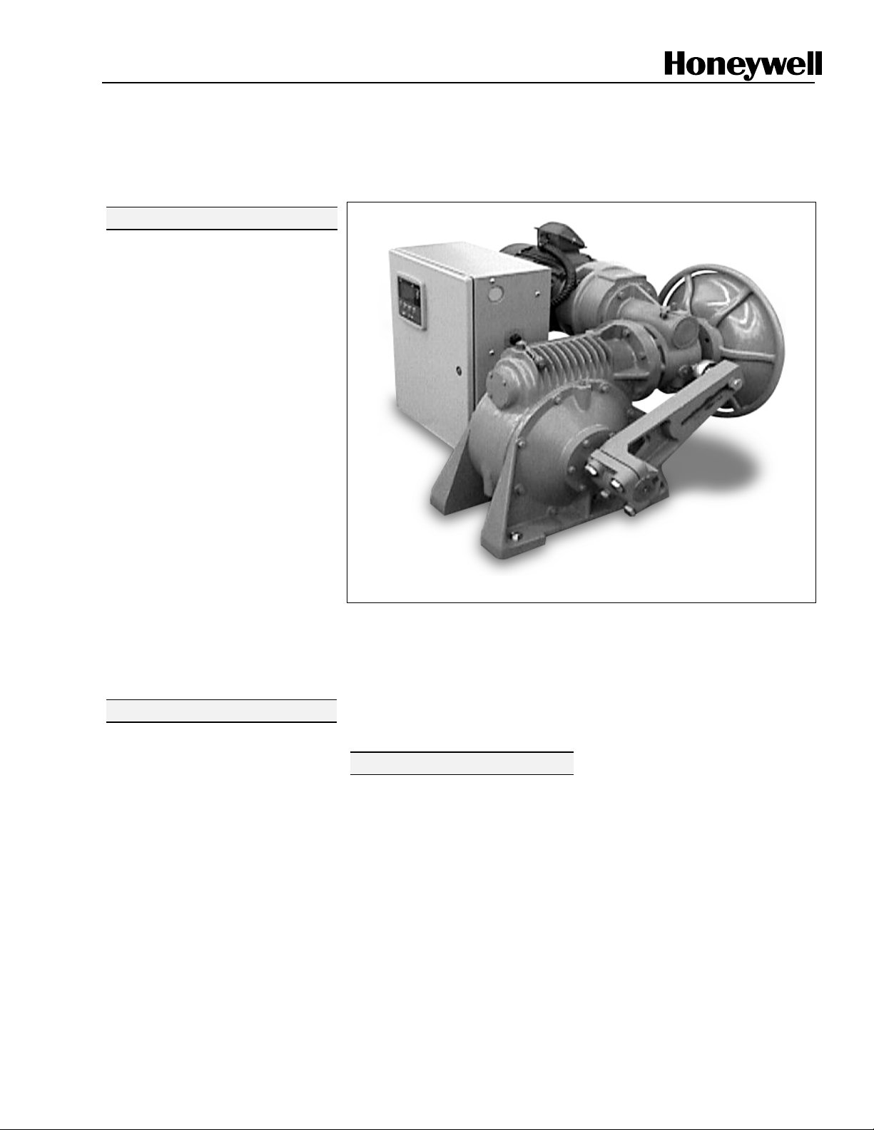
Honeywell’s HercuLine 11280S Smart
actuators incorporate all of the high
quality and reliable features of the
traditional HercuLine
the added benefits of a microprocessorbased Enhanced Electronics Unit (EEU).
These additional benefits provide:
•
Faster set-up and commissioning
•
Network capability
•
Health parameter monitoring for
proactive maintenance planning.
HercuLine 11280S Smart actuators
enable operation at maximum process
efficiency, minimal downtime, and
access to all actuator parameters for
real-time business decisions.
Honeywell’s 11280S actuators are
industrial rated and engineered for very
precise positioning of dampers and
valves. The HercuLine 11280S
performs especially well in extremely
demanding environments requiring
continuous duty, high reliability, and low
maintenance. Typical applications are
ID/FD fan dampers, furnace pressure
dampers, coal mill dampers, burner tilts
and more.
actuators plus
Actuator Operation
Microprocessor-based electronics
continually monitor the performance,
health, and position of the actuator for
repeatable positioning and response to
demand signal.
A double reduction worm gear set
combines with a variable speed motor
controller (inverter) that is continuous
duty rated for accurate and repeatable
positioning of final control elements.
The worm gear set combination also
functions as a brake, capable of holding
greater than two times the output torque
in a back-driving condition.
Figure 1 Herculine 11280S Smart Actuator
Control options are available to
interface with a modulating 4-20 mA
input signal and 4-20 mA customer
feedback or remote setpoint through
Modbus. Internal balance, customer
feedback and patented slidewire
emulation is provided by a noncontacting position sensor.
Features
Performance
• Accurate Positioning –
Motor/gear train provides accurate
positioning with almost
instantaneous start/stop
characteristics.
• Non-Contact Position Sensing –
Non-contacting sensing lowers
maintenance costs and improves
performance.
• Duty Cycle – Continuous duty
rated motor.
Specification
• Full Travel Speed – Full stroke
travel speeds as fast as 10
seconds.
• Torque – High torque capability in
small package (425 – 5,500 lb-ft).
• High Accuracy – Typically 0.25 %
of 90° span.
• High Repeatability - Typically
0.2 % of 90° span.
• Characterization – Linear, square
root or programmable userconfigured 21-point
characterization allows tailoring of
control for specific applications.
• Input Filter Setting – Four
programmable combinations of
input filter settings are provided to
accommodate various customers
needs. The combinations are
none, spike, low pass, or spike +
low pass filter.
• Deadband – Deadband is
programmable between 0.2 % to
5 % of 90° span.
Sensing and Control, 11 West Spring Street, Freeport, Illinois 61032
Printed in U.S.A. © Copyright 2000—Honeywell
Page 2

61-86-03-13
Page 2
Features (continued) Health Monitoring
Operation
• Control Signals – 0/4 to 20 mA,
0/1 to 5 Vdc, 0 to 10 Vdc, Digital
remote setpoint (RS485 Modbus
RTU protocol).
• Output Signals – 0/4 to 20 mA,
0/1 to 5 Vdc and slidewire
emulation.
• Manual Operation – All 11280S
series actuators are supplied with a
manual handwheel to operate the
actuator when power is not
available.
• Auto-Manual – electric handswitch
with auxiliary contacts indicating an
"Out-of-Auto" position is available
for local electric control.
• RS485/Modbus RTU
Communication – Simple and
easy to use Modbus RTU
communication is standard with all
11280S actuators allowing
seamless networking of Honeywell
control products.
• Auxiliary Outputs – Two types of
auxiliary outputs can be specified,
SPDT switches or
electromechanical relay outputs.
Relay outputs can be programmed
to output alarm conditions, provide
control of other equipment, or
indicate status.
• Alarm Functions – Alarms may be
assigned to relay outputs or may be
accessed through Modbus. Alarms
can be triggered from stall,
temperature limits, motor cycle
count, out of automatic mode,
digital input, position, input failure,
position sensor failure, power up
failure, and more.
• Local HMI Configuration – An
integral keypad and high intensity
display is available for non-intrusive
local configuration of the actuator
(Figure 2).
• Configuration Security –
Password protection is provided,
allowing users to lock out some, all,
or no groups of setup parameters to
prevent tampering.
• Factory Calibration – Factory
calibration is stored in non-volatile
memory and can be restored via
the local HMI at any time.
• Direction of Rotation – Direction
of rotation on increasing input
signal is programmable.
• Split Range Operation – Split
range is programmable and
infinitely adjustable.
• Digital Input Override – A digital
input is provided and is
programmable to provide override
of all other input signals as an
emergency override of control. The
digital input can be programmed to
drive the actuator open, closed,
remain in-place, or to a userspecified position on contact
closure.
• Failsafe – When input signal
exceeds high or low range limits
(or input signal failure), the
actuator can be programmed to
drive open, closed, remain inplace, or drive to a user-specified
position.
Construction
• Enclosure – Rugged, industrial
grade enclosure.
• Low Maintenance – Simple-
proven design means high
reliability/low maintenance.
• Output Shaft Hardware – All
11280S series actuators are
supplied with an adjustable radius
crank arm. Optional linkage kits
are available.
• Limit Switches – Two end-of-
travel electric limit switches are
supplied as standard equipment
with all 11280S series actuators.
• Warranty – Exceptional warranty.
A standard feature on all 11280S
actuators accumulates information
about actuator operation. This
information then can be used to
evaluate and determine predicted or
scheduled maintenance periods. The
parameters that are monitored include:
accumulated stall time, thermal
operating rating of the actuator
exceeded, number of motor starts in a
region of motor travel, total travel and
current actuator travel.
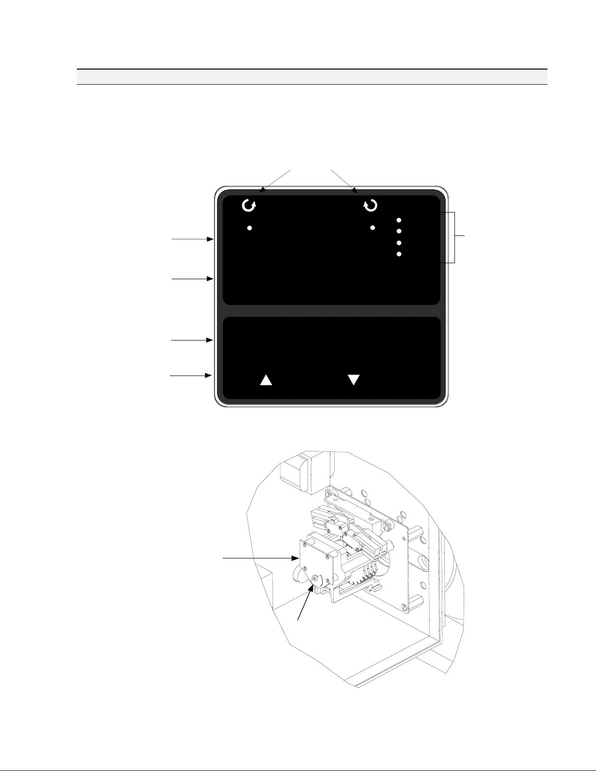
Non-Contact
Position Sensing
Honeywell 11280S series actuators
implement a variable inductance, noncontact position sensor mounted directly
to the actuator output shaft providing
precision position sensing from 0 to 90
degrees, (Figure 3). This technology
eliminates maintenance items such as
wipers, bearings, as well as static
friction, hysteresis and electrical noise
over a wide range of demanding
environmental conditions.
Slidewire Emulation
The Slidewire Emulation Circuit (SEC)
emulates the proportional voltage
output of a typical slidewire through a
high impedance circuit. The voltage
output is proportional to the supply
voltage and shaft position. A noncontact position sensor is used to
determine shaft position in place of the
slidewire.
Page 3
61-86-03-13
Page 3
Local Display and Keypad
Configuration and set-up is through the local HMI, consisting of a display and keypad interface (Figure 2). A high intensity
10-character LED display and simple pushbuttons provide quick access for actuator set up and status information. If relay
outputs are specified, all configuration can be done through either the local HMI interface. If mechanical switches are
specified, then the user must manually set the auxiliary output.
Control Arm Rotation
CCW CW
Upper Display
(Four Characters)
Lower Display
(Six Characters)
Indicators
STALLED
ALARM
MANUAL
AUTO
LED Status
Indicators
Pushbuttons to
Access Actuator
Set Up, Status and
Calibration
Parameters.
Non-Contact Sensor
Sensing PWA
FUNCTIONSET UP
MAN/AUTO
DISPLAY
Figure 2 Local HMI (Display and Keypad)
Non-Contact Sensor Spoiler
Figure 3 Non-Contact Sensor Assembly
Page 4

61-86-03-13
Page 4
Set Up/Configuration Parameters
Configuration parameters are logically grouped and accessed using the local HMI. Actuator calibration is also
accomplished through a simple procedure using the keypad. By pressing the SETUP button on the HMI, you can step
through the set up groups that contain all of the configuration parameters. The table below summarizes the configuration
parameters available within the various set up groups. Full details of all configuration parameters are found in the 11280S
Series Smart Actuator Installation, Operation and Maintenance Manual, document number 61-86-25-09.
Set Up Group Configuration Parameter Selections/Settings
SET INPUT Selects various
parameters that define actuator
operation.
SET RELAY When the actuator
is equipped with optional relays,
this set up group allows you to set
relay action for various actuator
operating conditions. Contact
closure can be wired to external
annunciators or alarm points to
indicate conditions for any of the
Relay Types.
SET CUROUT Selects the
current (or voltage) output range
of the actuator.
SET COMM Actuator can be
defined as a master or slave
device on a Modbus RTU RS-485
loop. Operating setpoint can be
transmitted to the actuator and
operating status can be read
when connected to supervisory
control systems.
SET DIGINP Selects digital
input action upon contact closure.
SET DISPLA Selects desired
decimal places and engineering
units for local display.
CAL INPUT, MTR, CURENT If needed, calibration of the actuator input, motor position and actuator output can be
performed using the local keypad and display.
IN TYP – Input Actuation Type
INP HI – Input High Range Value
INP LO – Input Low Range Value
FILTYP – Input Filter Type
LPFILT – Low Pass Filter Time Constant
Direct – Actuator Rotation
RTYPnn – Relay Type
Input Range
Position Range
Deviation
Upper or Lower Limit Travel
Temperature High or Low
Motor Starts
Motor Stalled
Manual Mode
Power Up Test Failure
Input Signal Failure
Position Sensor Signal Failure
Digital Input Closure
CUROUT - Output Signal Range
4 – 20 mA, 0 – 20 mA,
1 – 5V, 0 – 5V,
SW E (Slidewire Emulation)
COMM – Communications Parameters
ADDRES – Device Address
BAUD – Baud Rate
XmtDLY – Response Delay
DBLBYT – Floating Point Data Format
DIGINP – Digital Input State
Endpos – End Position Value
DECMAL – Decimal Point Location
EUNITS – Units Display
UNITS – Display Units
Dband – Input Deadband
FsTYP – Failsafe Type
FsVAL – Failsafe Value
CHAR – Input Characterization
LDCAL – Restore Calibration Type
RnnE – Relay Count Multiplier
RnnVAL – Relay Value
Rnn HL – Relay High/Low
RLYnHY – Relay Hysteresis
Continued on next page ⇒
Page 5

Set Up Group Configuration Parameter Selections/Settings
61-86-03-13
Page 5
SET LOCK Enables lock
out or access to selected
set up group parameters
and calibration values.
READ STATUS
Displays failsafe condition
and the results of various
diagnostics performed
during power up.
SET DRVINF Allows
access to actuator device
information.
SET MAINT Allows
access to parameters that
monitor operating
conditions.
Physical
LOCKID – Set Security Password
LOCK – Lock Out
FAILSF – Failsafe
RAMTST – RAM Test Diagnostic
SEETST – Serial EEPROM Test
Diagnostic
VERSON – Firmware Version
SPEED – Stroke Speed
POWER – Power Input Voltage and Line
Frequency
TAG – Tag Name
TEMP – Actuator Temperature
TEMPHI – High Temperature Limit
TEMPLO – Low Temperature Limit
ACST – Accumulated Motor Stall Time
STARTS – Accumulated Motor Starts
Specifications – General
CFGTST – Configuration Test Diagnostic
CALTST – Calibration Test Diagnostic
MFGDAT – Manufacturing Date
LREP – Date of Last Repair
LCAL – Date of Last Field Calibration
REPTYP – Repair Type
RLnCNTS – Relay Cycle Counts
REGNn – Accumulated Motor Starts
(Regions of Travel)
TOTDEG – Total Degrees of Motor Travel
MANRST – Reset Maintenance Statistics
Enclosure
Gear Train
Operating Temperature
Storage Temperature
Relative Humidity
Crank Arm
Rotation
Direction of Rotation
Manual Handwheel
Lubrication
Weight
Precision-machined ductile iron with corrosion resistant paint
Precision-machined double reduction worm gear
-30 °C to +65 °C (-20 °F to +150 °F)
except Model 11287S which has a range of: -20 °C to +65 °C (-4 °F to +150 °F)
-40 °C to +93 °C (-40°F to +200 °F)
0-99% R.H. noncondensing, over the full operating temperature range.
Adjustable radii (8” to 14”) crank arm is standard
Factory set to 90 degrees, for 0% to 100% travel
Field programmable via local display and keypad
Provides a means of positioning the actuator in the event of a power failure or set-up
Mobil Synthetic bearing and gear lubricant SHC 634 (ISO 460) or equivalent
300 lb to 600 lb (136 kg to 272 kg)—See Table below for more information.
Specifications continued on next page ⇒
Page 6

61-86-03-13
Page 6
Physical
Specifications – General, Continued
Model #
11284S 425
11285S 840
11286S 1500
11288S 2500
11289S 4000
11287S 5500
Torque
lb-ft (N_M)
(576)
(1139)
(2033)
(3389)
(5423)
(7457)
Electrical
Mains Supply
Motor
Output
Shaft Size
2"
(51 mm)
2"
(51 mm)
2"
(51 mm)
2-1/2"
(64 mm)
2-1/2"
(64 mm)
2-1/2"
(64 mm)
115/220 Vac, single phase 50/60 Hz up to 1500 lb-ft
208/200 – 240/380 – 480/575 Vac, three phase 50/60 Hz
Inverter rated, continuous duty, C face mounting
Shaft Key
Size
1/2"
(13 mm)
1/2"
(13 mm)
1/2"
(13 mm)
5/8"
(16 mm)
5/8"
(16 mm)
5/8"
(16 mm)
Output
Shaft
Length
5"
(127 mm)
5"
(127 mm)
5"
(127 mm)
6"
(152 mm)
6"
(152 mm)
6"
(152 mm)
Maximum
Overhang
Load
3700 lb.
(1678 kg)
3700 lb.
(1678 kg)
3700 lb.
(1678 kg)
7500 lb.
(3402 kg)
7500 lb.
(3402 kg)
7500 lb.
(3402 kg)
Handwheel
Diameter
18"
(457 mm)
18"
(457 mm)
18"
(457 mm)
18"
(457 mm)
18"
(457 mm)
18"
(457 mm)
Approx.
Maximum
Weight
300 lb.
(136 kg)
300 lb.
(136 kg)
300 lb.
(136 kg)
550 lb.
(251 kg)
600 lb.
(272 kg)
600 lb.
(272 kg)
Motor Current Motor Size Full Load Amps (FLA)
(Horsepower) @ 230 Vac @ 460 Vac
Loss of Power
Local Auto - Manual
Switch
Limit Switches
Auxiliary
Switches/Relays
Installation Category
(Overvoltage Category)
Pollution Degree
½
¾
1
1 ½
2
3
Stays in place
Allows local manual and automatic operation of the actuator
Standard - Two SPDT end-of-travel limits rated 10 A at 125 Vac, 5 A at 250 Vac.
Optional – Up to 2 additional SPDT switches (or 4 relay outputs, programmable)
Category II: Energy-consuming equipment supplied from the fixed installation. Local level
appliances, and industrial control equipment. (EN 61010-1)
Pollution degree 2: Normally non-conductive pollution with occasional conductivity caused by
condensation. (ref. IEC 664-1)
1.6
2.2
2.6
4.4
5.6
7.8
0.8
1.1
1.3
2.2
2.8
3.9
Page 7

61-86-03-13
Specifications – Actuator
Electrical
Input Signals Analog: 0/4 to 20 mA (With supplied 250 ohm shunt resistor for current range)
0/1 to 5 Vdc
0 to 10 Vdc
Digital: Remote Setpoint via Modbus RTU (RS485)
Page 7
Input Impedance
Input Characterization
Sensitivity
Hysteresis
Deadband
Repeatability
Voltage/ Supply Stability
Temperature Coefficient
Zero Suppression
Input Filters
Solid State Motor Control
Input
0/4 to 20 mA
0/1 to 5 Vdc
Provides characterization of the input signal.
Selections are: Linear, Square Root or Custom.
0.2 % to 5 % of 90° span, proportional to deadband
Less than 0.4 % of full scale
0.2 % to 5 % of 90° span, adjustable. Shipped at 0.5%
0.2 % of 90° span
0.25 % of span with +10/-15 % voltage change
Less than ± 0.030 % of span per degree C for 0 °C to 50 °C
Less than ± 0.05 % of span per degree C for
90% of span
Selectable spike and low pass filters
CW/CCW open collectors (opto-isolators) for use as discrete control inputs to the inverter
for motor operation.
Input Impedance
250 ohms
10 K ohms
-30 °C to 65 °C
Failsafe operation
Feedback signals/Output
Slidewire Emulation
Isolation
Load Requirement (4-20)
Programmable Functions
If input signal exceeds configured input range. Selectable and adjustable.
0 to 20 mA, 4 to 20 mA
0 to 5 Vdc, 1 to 5 Vdc with 250 ohm resistor; (0 to 16 Vdc with 800 ohm resistor)
Provides output voltage ratiometric to shaft position and potentiometric to supply voltage
(1 to 20 Vdc) without a slidewire. Emulates a 100 ohm to 1000 ohm slidewire. 10 mA
output maximum.
Input signal, output signal and power are isolated from each other.
Current Out — 0 to 1000 ohms
Selectable and configurable operating parameters:
• Input range
• Input filtering
• Input characterization
• Security
• Digital Input action
• Deadband
• Failsafe on loss of
input signal
• Failsafe on loss of
position sensor
• Direction of rotation
• Relay closure
action
• Communication
parameters
• Split range
operation
• Output range
• Alarms
Page 8

61-86-03-13
Page 8
Pipe Linkage Kit
Pipe linkage kits are available from Honeywell and can be used for linkage lengths from 24 to 240 inches (61 to 610 cm). The
kits include the mechanical pipe couplings, load rod end (left-hand thread), connecting rods and locking nuts. See Figure 4.
The actuator rod end (right-hand thread), nut and bolt are supplied with the actuator. The customer must supply a piece of
schedule 40 pipe 2 ½” * (both ends with right-hand NP threads) and a nut and bolt to connect the rod end to the load. Pipe
linkage kits can be ordered with the Actuator using Table VIII of the Model Selection Guide.
Linkage Minimum = 24in. (61 cm)
Linkage Maximum = 240in. (610 cm)
+
Pipe Length *
*Pipe length = Overall linkage length minus (-) 20 inches (51 cm).
Figure 4 Pipe Linkage Kit
Actuator Crank Arm
The 11280S Series Actuator comes standard with an 8” to
14” adjustable radius crank arm. The crank arm uses a
standard right-hand thread 1” rod end to compliment the
pipe linkage kit.
The crank arm for the 11284S, 11285S and 11286S has a
2” shaft hole, while the crank arm from the 11287S, 11288S
and 11289S has a 2 ½” shaft hole.
This rod end
supplied on Actuator
with crank arm
+
Recommended Bolt Torque
The table below lists the type of bolts to be used and the
recommended torque for each bolt.
Bolt Type Torque
Clamp bolts 220 lb.-ft
Rod End Bolt 220 lb.-ft
Jam nuts 100 lb.-ft
Figure 5 11280S Crank Arm
Page 9

61-86-03-13
External Transformers
120 Vac (Single Phase)
For customer applications requiring 120/240 Vac single phase operation, a step-up transformer is mounted in a separate
enclosure (Model Selection Guide Table I, option 1). Figure 6 shows the installation for the transformer enclosure.
575 Vac (3 Phase)
For customer applications requiring 575/460 Vac 3 phase operation, a step-down transformer is mounted in a separate
enclosure (Model Selection Guide Table I, option 6). Figure 6 shows the installation for the transformer enclosure.
14.0
(355.6 mm)
Ground
Stud
Page 9
120/240 Vac
Single Phase
Transformer
575/460 Vac
Three Phase
Transformer
10.0
(254 mm)
16.0
(406.4 mm)
Figure 6 Installation Drawing for External Transformer
Enclosure
Page 10

61-86-03-13
_-_
_
_
_ _IV_
_
_
_
_
_
Page 10
Model Selection Guide Reference 62-86-16-19
Instructions
Select the desired key number. The arrow to the right marks the selection available.
Make the desired selections from Tables I thru VIII using the column below the arrow.
A dot ( ) denotes unrestricted availability.
Key Number I II VI VII VIII IX
_ _ _ _ _ _ _
-
KEY NUMBER - Electronics
Output Torque
(lb. - ft.) (N - M)
425 (575)
850 (1150)
III
----_-
_
V
_
(Note 1)
(Note 1)
- -_
_ _ _ _
Selection Availability
011284S
011285S
1500 (2025) 011286S
2500 (3400) 011288S
4000 (5425) 011289S
5500 (7450) 011287S
TABLE I - POWER SUPPLY
Single Phase 120 Vac, 50/ 60 Hz
240 Vac, 60 Hz / 200 Vac, 50 Hz a
Three Phase 200 - 240 Vac, 60 Hz
380 - 480 Vac, 50-/60 Hz
575 Vac, 60 Hz
1
2
4
5
6
a
TABLE II - STROKE SPEED
Stroke Speed @ 60 Hz 10 sec/90 degrees
30 sec/90 degrees
60 sec/90 degrees
1
2
3
TABLE III - MOTOR ORIENTATION
Motor Right-hand floor configuration, H.W. Shaft Horizontal
Orientation Left-hand floor configuration, H.W. Shaft Horizontal
(See specification 61-86-03-13 for diagrams)
01
03
TABLE IV - ANALOG INPUT/OUTPUT SIGNALS
Input 4-20 mA, 0-20mA (1-5 Vdc, 0-5 Vdc, 1-10 Vdc, 0-10Vdc) 0 _ _
Output No Analog Position Output _ 00
4-20 mA, 0-20mA (1-5 Vdc, 0-5 Vdc, 1-10 Vdc, 0-10Vdc) _ 20
Slidewire Emulation
(Note 2)
_ 40
Page 11

61-86-03-13
S
Page 11
Model Selection Guide, continued
01128_ _
4S
5S
6S
8S
TABLE V - SWITCH AND RELAY OUTPUT
Auxiliary Switches None
and 2 Aux. SPDT Switches
2 Aux. + 2 Programmable Relay Outputs
2 Programmable Relay Outputs
4 Programmable Relay Outputs
Auto/Manual Switch None
One Auto/Manual Switch with Out-of-Auto Contact
TABLE VI - CONFIGURATION INTERFACE
Remote None 0
Local Integrally mounted local display/keypad interface 1
(2 mech end-of-travel limits standard) Selection 9S 7S
00 _
20 _
22 _
02 _
04 _
_ _0
_ _1
TABLE VII - COMMUNICATIONS/PROTOCOL
Modbus RTU RS485 RS-485 Modbus compliant - standard with EEU 0
Additional Communications Future 1
TABLE VIII - OPTIONS
Crank Arm Adjustable 8" to 14" Radii - Standard 0_ _ _ _ _
None 1_ _ _ _ _
Linkage Kit None _0_ _ _ _
Up to 20 ft. length - customer supplies schedule 40 pipe _1_ _ _ _
Future Option None _ _0_ _ _
Future Option None _ _ _0_ _
Tagging None _ _ _ _0_
Linen (Note 3) _ _ _ _1_
Stainless Steel (Note 3) _ _ _ _2_
Future Option None _ _ _ _ _0
TABLE IX - FACTORY OPTIONS
Motor Orientation None 00
RESTRICTIONS
Restriction Available Only With Not Available With
Letter Table Selection Table Selection
a
I 11284S, 11285S, 11286S I 11287S, 11288S, 11289S
Note 1: Requires (2) adapters PN 51204694-501 for retrofit of existing Leeds & Northrup 011284 and 011285 actuators.
Note 2: Slidewire emulation is a solid state circuit providing a ratiometric voltage output proportional to shaft position.
Note 3: Customer must supply tagging information: Up to 3 lines (22 characters for each line)
Page 12

61-86-03-13
Page 12
Figure 7 Mounting and Outline Dimensions for 11284S, 11285S, 11286S, 11288S, and 11289S
Weather-Proofed Motor Actuators -
Right Hand Floor Mounting, Handwheel Shaft Horizontal (D-MTG-616-200)
Page 13

61-86-03-13
Page 13
Figure 8 Mounting and Outline Dimensions for 11284S, 11285S, 11286S, 11288S, and 11289S
Weather-Proofed Motor Actuators -
Left Hand Floor Mounting, Handwheel Shaft Horizontal (D-MTG-616-210)
Page 14

61-86-03-13
Tlf: 67150 250 Faks: 67 150 251
Mail: post@instrumentteam.no
Web: www.instrumentteam.no
Page 14
Warranty/Remedy
Honeywell warrants goods of its manufacture as being free of defective materials and faulty workmanship.
Contact your local sales office for warranty information. If warranted goods are returned to Honeywell during
the period of coverage, Honeywell will repair or replace without charge those items it finds defective. The
foregoing is Buyer's sole remedy and is in lieu of all other warranties, expressed or implied, including
those of merchantability and fitness for a particular purpose. Specifications may change without
notice. The information we supply is believed to be accurate and reliable as of this printing. However, we
assume no responsibility for its use. © Honeywell 2004.
While we provide application assistance personally, through our literature and the Honeywell web site, it is
up to the customer to determine the suitability of the product in the application.
Distributor :
Sensing and Control
Honeywell
11 West Spring Street
Freeport, IL 61032
2-86-03-13 9/01 Printed in USA www.honeywell.com/imc 6
 Loading...