

Page 1

10260S HercuLine® Smart Actuator
Installation, Operation and
Maintenance Manual
Doc. No.: 62-86-25-08
Revision: 5
Date: 7/07
Honeywell Field Solutions
Page 2

Notices and Trademarks
Copyright 2007 by Honeywell
Revision 5 July 2007
Warranty/Remedy
Honeywell warrants goods of its manufacture as being free of defective materials and faulty workmanship. Contact
your local sales office for warranty information. If warranted goods are returned to Honeywell during the period of
coverage, Honeywell will repair or replace without charge those items it finds defective. The foregoing is Buyer's sole
remedy and is in lieu of all other warranties, expressed or implied, including those of merchantability and
fitness for a particular purpose. Specifications may change without notice. The information we suppl y is believed
to be accurate and reliable as of this printing. However, we assume no responsibility for its use.
While we provide application assistance personally, throug h our literature and the Honeywell web site, it is up to the
customer to determine the suitability of the product in the application.
CE Conformity
This product conforms with the protection requirements of the following European Council Directive: 89/336/EEC, the
EMC directive and 73/23/EEC, the Low Voltage Directive. Conformance of this product with any other “CE Mark”
Directive(s) shall not be assumed.
Attention
The emission limits of EN 50081-2 are designed to provide reasonable protection against harmful interference when
this equipment is operated in an industrial environment. Operation of this equipment in a residential ar ea may cause
harmful interference. This equipment generates, uses, and can radiate radio frequenc y energy and may cause
interference to radio and television reception when the equipment is used closer than 30 m to the antenna(e). In
special cases, when highly susceptible apparatus is used in close proximity, the user may have to employ additional
mitigating measures to further reduce the electromagnetic emissions of this equipment
Industrial Measurement and Control
Honeywell
1100 Virginia Drive
Fort Washington, PA 19034
LeaderLine and Herculine are U.S. registered trademarks of Honeywell
Other brand or product names are trademarks of their respective owners.
ii 10260S HercuLine® Actuator Installation, Operation and Maintenance Manual Revision 5
7/07
Page 3

About This Document
Abstract
This manual describes the installation, set up, operation, maintenance, and troubleshooting of the 10260S
series of Smart Actuators.
References
The following list identifies all documents that may be sources of reference for material discussed in this
publication.
Document Title Doc ID
Herculine 10260 S Smart Actuator Specification and Model
Selection Guide
Modbus® RTU Serial Communications User Manual
Modbus
Communication Interface for Smart Actuator
HercuLink User Manual 62-86-25-11
Installation and Operation Manual Hart Communications 62-86-25-12
®
RTU Serial Communications User Manual
62-86-03-12
51-52-25-66
51-52-25-103
Contacts
World Wide Web
The following lists Honeywell’s World Wide Web sites that will be of interest to our customers.
Honeywell Organization WWW Address (URL)
Corporate http://www.honeywell.com
Industrial Measurement and Control http://www.honeywell.com/imc
Telephone
Contact us by telephone at the numbers listed below.
United States and Canada Honeywell
Organization Phone Number
1-800-423-9883 Tech. Support
1-888-423-9883 Q&A Faxback
(TACFAQS)
1-800-525-7439 Service
Revision 5 10260S HercuLine® Actuator Installation, Operation and Maintenance Manual iii
7/07
Page 4
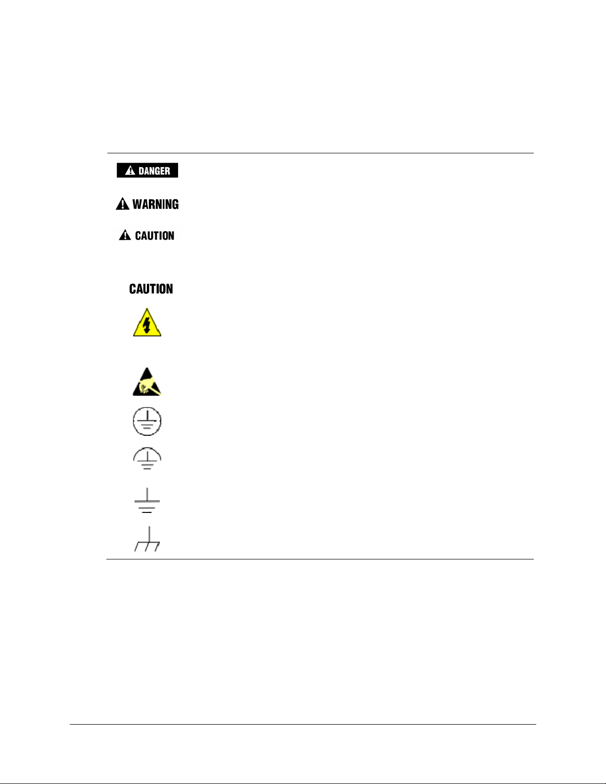
Symbol Definitions
The following table lists those symbols used in this document to denote certain conditio ns.
Symbol Definition
This DANGER symbol indicates an imminently hazardous situation, which,
if not avoided, will result in death or serious injury.
This WARNING symbol indicates a potentially hazardous situation, which, if
not avoided, could result in death or serious injury.
This CAUTION symbol may be present on Control Product instrumentation
and literature. If present on a product, the user must consult the
appropriate part of the accompanying product literature for more
information.
This CAUTION symbol indicates a potentially hazardous situation, which, if
not avoided, may result in property damage.
WARNING
PERSONAL INJURY: Risk of electrical shock. This symbol warns the user of a
potential shock hazard where HAZARDOUS LIVE voltages greater than 30 Vrms,
42.4 Vpeak, or 60 Vdc may be accessible. Failure to comply with these
instructions could result in death or serious injury.
ATTENTION, Electrostatic Discharge (ESD) hazards. Observe precautions for
handling electrostatic sensitive devices
Protective Earth (PE) terminal. Provided for connection of the protective earth
(green or green/yellow) supply system conductor.
Functional earth terminal. Used for non-safety purposes such as noise immunity
improvement. NOTE: This connection shall be bonded to protective earth at the
source of supply in accordance with national local electrical code requirements.
Earth Ground. Functional earth connection. NOTE: This connection shall be bonded
to Protective earth at the source of supply in accordance with national and local
electrical code requirements.
Chassis Ground. Identifies a connection to the chassis or frame of the equipment
shall be bonded to Protective Earth at the source of supply in accordance with
national and local electrical code requirements.
iv 10260S HercuLine® Actuator Installation, Operation and Maintenance Manual Revision 5
7/07
Page 5

Contents
Contents..................................................................................................v
1. Introduction ........................................................................................1
Product Description......................................................................................................1
Applications..................................................................................................................1
Features .......................................................................................................................2
Honeywell Linkage Kits ................................................................................................5
HAL Software Application.......................................................................................................5
2. Specifications.....................................................................................7
Technical and Operating Specifications.......................................................................7
Model Selection Guide ...............................................................................................11
Contents
3. Installation........................................................................................13
Installation Overview ..................................................................................................13
Before Starting............................................................................................................14
Installation Considerations...................................................................................................14
Actuator Mounting ......................................................................................................14
Outline Dimension Drawings................................................................................................14
Mechanical Installation...............................................................................................17
Linkage Set-up.....................................................................................................................17
Electrical Installation...................................................................................................22
4. Set Up and Calibration Procedures
Overview.....................................................................................................................28
Local Display and Keypad..........................................................................................28
Set Up Tips.................................................................................................................30
Set Up Groups............................................................................................................30
Set Up Procedure.......................................................................................................32
Input Set Up Group.....................................................................................................34
Equal Percentage Valve Characteristic................................................................................37
Quick Opening Valve Characteristic.....................................................................................38
..................................................28
Relays Set Up Group..................................................................................................39
Relay Examples...................................................................................................................41
Current Out Set Up Group..........................................................................................43
Communications Set Up Group..................................................................................45
Digital Input Set Up Group .........................................................................................46
Revision 5 10260S HercuLine® Actuator Installation, Operation and Maintenance Manual v
7/07
Page 6

Contents
Display Set Up Group.................................................................................................46
Lock Set Up Group.....................................................................................................47
Set/Change Password .........................................................................................................48
Read Status Set Up Group.........................................................................................49
Drive Set Up Group....................................................................................................50
Set Tag Name......................................................................................................................52
Maintenance Set Up Group........................................................................................53
CAL POSOUT Group .................................................................................................55
Auto - Manual Drive Switch........................................................................................55
Calibration ..................................................................................................................57
Setting End-of-Travel Limit Switches (actuators mfd. pre-1/1/03) .............................67
Setting End-of-Travel Limit Switches (actuators mfd. after 1/1/03)............................68
Setting Auxiliary Switches (actuators mfd. pre-1/1/03) ..............................................70
Setting Auxiliary Switches (actuators mfd. after 1/1/03).............................................73
5. Start-Up/Operation...........................................................................74
Power Up Diagnostics................................................................................................74
Operations Checklist ..................................................................................................74
Operating the Local Display at High Temperatures...................................................75
Operating Displays.....................................................................................................75
Motor Stall ..................................................................................................................75
Non-Contact Sensor Operation..................................................................................76
Remote Setpoint Operation........................................................................................76
Regions of Motor Travel.............................................................................................77
6. Control Applications ..........................................................................78
Split Range.................................................................................................................78
Master/Slave Arrangement.........................................................................................79
7. Maintenance.....................................................................................85
Basic Maintenance.....................................................................................................85
Spur Gear Lubrication..........................................................................................................85
Replacement Procedures...........................................................................................87
8. Replacement/Recommended Spare Parts
Linkage Parts/Kits.......................................................................................................96
Honeywell Actuator Linkage Analysis Software (HAL)...............................................96
.......................................89
9. Troubleshooting................................................................................97
vi 10260S HercuLine® Actuator Installation, Operation and Maintenance Manual Revision 5
7/07
Page 7

Introduction.................................................................................................................97
Troubleshooting Procedures ......................................................................................98
Appendix A - 10260S Configuration Record Sheet.............................105
Index ...................................................................................................109
Contents
Revision 5 10260S HercuLine® Actuator Installation, Operation and Maintenance Manual vii
7/07
Page 8

Contents
Tables
Table 1 Specifications - General.............................................................................................................................7
Table 2 Recommended Minimum Wire Size............................................................................................................22
Table 3 Actuator Terminal Connections...................................................................................................................24
Table 4 Keypad Description..................................................................................................................................... 29
Table 5 Set Up Tips..................................................................................................................................................30
Table 6 Set Up Groups .............................................................................................................................................31
Table 7 Set Up Procedure Using Display and Keypad.............................................................................................32
Table 8 Input Set Up Group Parameters...................................................................................................................34
Table 9 Equal Percentage Valve Characteristic Table...............................................................................................37
Table 10 Quick Opening Valve Characteristic Table................................................................................................38
Table 11 Relay Set Up Group Parameters.................................................................................................................39
Table 12 Relay Type Descriptions............................................................................................................................40
Table 13 Current Out Set Up Group Parameters......................................................................................................43
Table 14 Communications Set Up Group Parameters ..............................................................................................45
Table 15 Digital Input Set Up Group Parameters.....................................................................................................46
Table 16 Display Set Up Group Parameters.............................................................................................................46
Table 17 Lock Set Up Group Parameters.................................................................................................................47
Table 18 Read Status Set Up Group Parameters ......................................................................................................49
Table 19 Drive Set Up Group Parameters ................................................................................................................50
Table 20 Maintenance Set Up Group Parameters.....................................................................................................53
Table 21 CAL POSOUT Group Parameters.............................................................................................................55
Table 22 Auto - Manual Switch Functions...............................................................................................................56
Table 23 Input Calibration Procedure.......................................................................................................................60
Table 24 Motor Calibration Procedure.....................................................................................................................61
Table 25 Output Calibration Procedure....................................................................................................................62
Table 26 Slidewire Emulation Calibration Procedure...............................................................................................63
Table 27 Non Contact Sensor Calibration Procedure...............................................................................................65
Table 28 Load NCS Factory Calibration..................................................................................................................66
Table 29 Typical Operating Displays.......................................................................................................................75
Table 30 Split Range Set Up Procedure ...................................................................................................................78
Table 31 Spur Gear Lubrication Procedure..............................................................................................................85
Table 32 Motor Drive Fuse Replacment Procedure..................................................................................................87
Table 33 Relay PWA Replacement Procedure.........................................................................................................88
Table 34 Observable Symptoms of Failure..............................................................................................................97
viii 10260S HercuLine® Actuator Installation, Operation and Maintenance Manual Revision 5
7/07
Page 9

Figures
Figure 1 10260S Smart Actuator................................................................................................................................2
Figure 2 10260S Internal View...................................................................................................................................3
Figure 3 Outline and Dimensions of Herculine Models 10261S, -62S, -64S, -66S, -67S, -68S, and -69S Actuators15
Figure 4 Outline and Dimensions of Herculine Models 10263S and 10265S Actuators.......................................... 16
Figure 5 Constant Torque Linkage...........................................................................................................................17
Figure 6 Constant Torque Profile.............................................................................................................................17
Figure 7 Variable Torque Linkage ...........................................................................................................................18
Figure 8 Variable Torque Profile..............................................................................................................................18
Figure 9 Turnbuckle Linkage Kit.............................................................................................................................19
Figure 10 Pipe Leakage Kit......................................................................................................................................19
Figure 11 Standard 5-Inch Crank Arm.....................................................................................................................20
Figure 12 Projecting Scale Option Exploded View..................................................................................................21
Figure 13 Actuator Terminal Connections ...............................................................................................................26
Figure 14 Modbus terminals......................................................................................................................................26
Figure 15 10260S Display and Keypad.................................................................................................................... 28
Figure 16 Auto - Manual Switch..............................................................................................................................56
Figure 17 Calibration Wiring Connections (except slidewire emulation)................................................................58
Figure 18 Calibration Wiring Connections (slidewire emulation).............................................................................59
Figure 19 Location of NCS Assembly......................................................................................................................66
Figure 20 Location of Auxiliary Switches.................................................................................................................71
Figure 21 End of Travel Limit Switch Settings........................................................................................................72
Figure 22 Auxiliary Switch Settings..........................................................................................................................72
Figure 23 Terminal Block Connections for Modbus Communications....................................................................77
Figure 24 Regions of Motor Travel..........................................................................................................................77
Figure 25 Flow Diagram...........................................................................................................................................79
Figure 26 Interconnection Diagram.......................................................................................................................... 79
Figure 27 Proportional Flow Using Multiple Actuators........................................................................................... 80
Figure 28 Multiple Actuator Interconnection Diagrams...........................................................................................81
Figure 29 Interconnection Diagrams........................................................................................................................82
Figure 30 Spur Gear Location ..................................................................................................................................86
Figure 31 Power Distribution PWA and Relay PWA Locations..............................................................................87
Figure 32 Motor Drive Circuit Fuses........................................................................................................................88
Figure 33 10260S Actuator Components..................................................................................................................89
Figure 34 Test for Actuator Operation .....................................................................................................................99
Figure 35 Power Up Diagnostics............................................................................................................................100
Figure 36 Test Power Distribution PWA................................................................................................................102
Figure 37 Test AUTO - MANUAL Switch............................................................................................................103
Figure 38 Test Relay Function ............................................................................................................................... 104
Revision 5 10260S HercuLine® Actuator Installation, Operation and Maintenance Manual ix
7/07
Page 10

Page 11

Product Description
Honeywell's 10260S industrially rated rotary smart actuators are precision engineered for exceptional
reliability, accurate positioning, and low maintenance. (Figure 1) Designed for very precise positioning of
pers and quarter turn valves in the power and processing industries, the 10260S performs especially
dam
well in extremely demanding environments requiring continuous-duty, high reliability, and low
maintenance.
Precise positioning of the actuator is achieved through state-of-the-art motor control and positioning
electronics. The motor starts and stops almost instantaneously, preventing overshoot and hunting.
Positioning repeatabililty of 0.2% span or better is achievable for extremely tight process control to take
full advantage of modern controllers.
A no-burnout synchronous induction motor is combined with a heavy-duty precision-machined output
worm gear mesh providing a responsive, low maintenance, and non-backdriving actuator. Accidental stalls
up to 100 hours can be withstood without damage to the gear train. End-of-travel limit switches are
provided as standard equipment to prevent damage to the valve or damper and are backed up by mechanical
stops.
1. Introduction - Product Description
1. Introduction
Honeywell electric actuators provid e instantaneous response to a demand signal, eliminating system nonlinearity due to dead time. Additionally, since the actuator is electric, the costs associated with providing
and maintaining a clean, dry air supply are eliminated.
A heavy duty cast crank arm and precision rod-end bearing is provi de d wi t h each 102 60 S act uat or. Cran k
arms can be positioned at any angle on the output shaft and an adjustable radius is provided to allow
flexibility in linkage set-up.
All 10260S actuators are equipped with a manual handwheel for operation during loss of power or
installation. A local auto/manual handswitch can be provided for local operation and has an “out of auto”
contact to annunciate that condition.
Applications
Honeywell actuators have a long and respected history in the industrial actuator market. 10260S actuators
are designed for precision modulation of final control devices such as dampers, vanes, fluid couplings,
scoop tubes, fuel/air ratio valves, windbox dampers, and coal mill dampers, and quarter turn valves. The
robustness of the design serves as the basis for long-term reliability and reduced operating costs.
Revision 5 10260S HercuLine® Actuator Installation, Operation and Maintenance Manual 1
7/07
Page 12
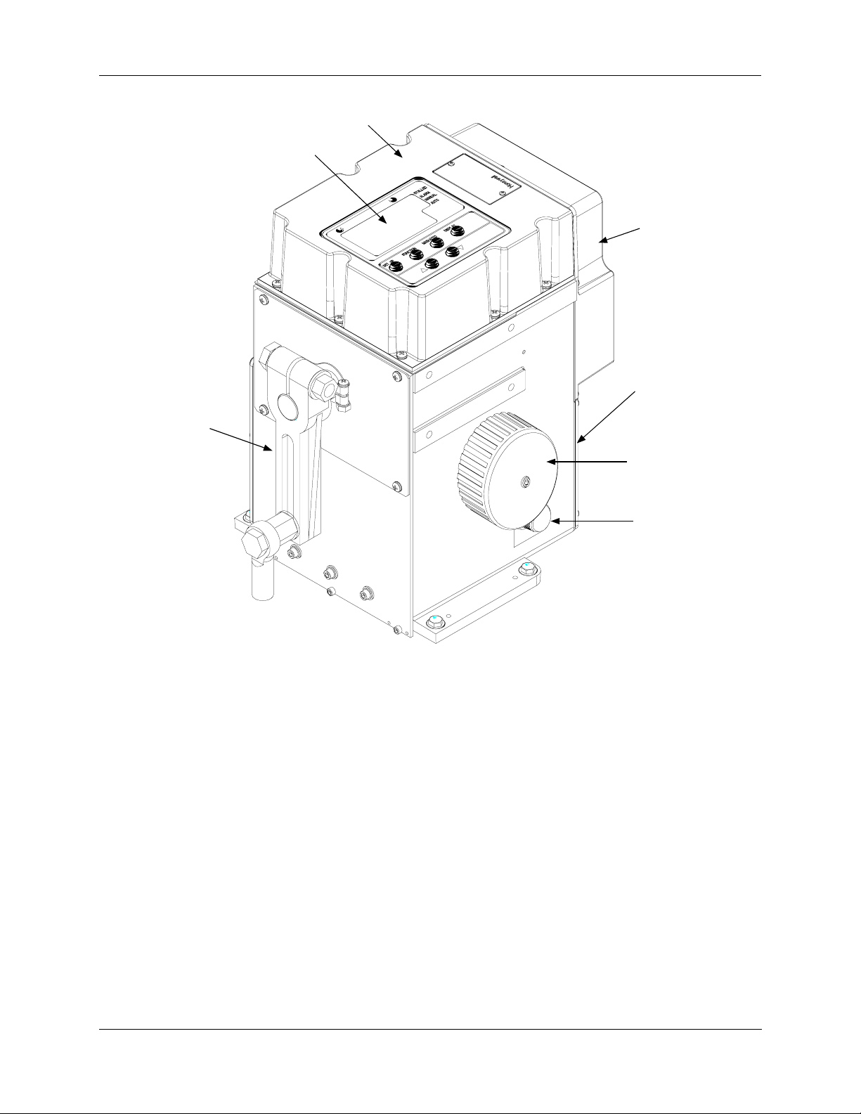
1. Introduction - Features
Local Display
and Keypad
Crank Arm and
Rod End
Top Cover
Extended
Cover
Terminal Cover
(Access to cust omer
connections)
Handwheel
Figure 1 10260S Smart Actuator
Features
Non-contact Position Sensing (NCS) with True Shaft Position Indication
Non-contact position sensing eliminates maintenance problems and nuisance shutdowns that are common
with slidewire or potentiometer position sensing. The non-contact position sensor replaces the slidewire
and wiper assembly for position sensing. Once calibrated, the non-contacting position sensor requires no
maintenance.
The non-contact position sensing assembly consists of a position sensor and a bracket as shown in
e position sensor “spoiler” is connected directly to the output shaft, reflecting true shaft position. As the
Th
output shaft rotates, the sensor “spoiler” rotates and the sensing circuit board detects the change in position.
Sensing is accomplished by changing the magnetic field created by the coils in the sensing circuit board.
There is no contact between circuit board and spoilers.
Auto-Manual
Switch
Figure 2.
2 10260S HercuLine® Actuator Installation, Operation and Maintenance Manual Revision 5
7/07
Page 13
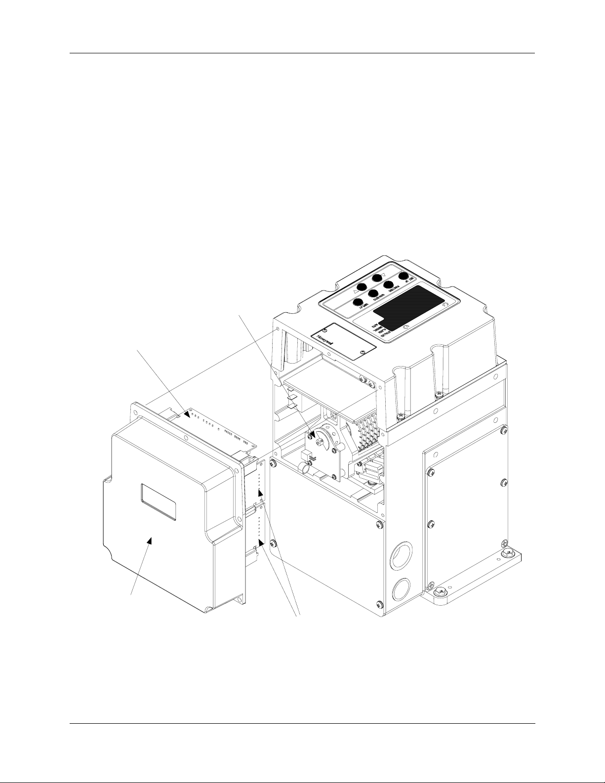
Slidewire Emulation
A truly unique feature, slidewire emulation allows direct replacement of existing three-wire control
actuators without requiring controller changes while gaining all of the advantages of the maintenance-free
non-contact sensing. This is ideal for replacement of installed actuators that cause control problems due to
slidewire wear.
The slidewire emulation assembly consists of a non-contact position sensor and a bracket as shown in
Figure 2. The position sensor is identical to that describ
feature.
A potentiometric voltage from the controller is supplied to the slidewire emulation circuit. This voltage is
ratiometrically conditioned with respect to the output shaft position from 0 to 100% and is available to the
controller. Voltages of 1 to 18 Vdc are accepted and this device will emulate 100 to 1000 ohm slidewires.
Power
Distribution
PWA
1. Introduction - Features
ed previously in the non-contact position-sensing
Non-contact
Sensor
Customer
Terminal
Connections
behind this Cover
Extended
Cover Assembly
and Main PWA
Relay PWAs
Figure 2 10260S Internal View
Revision 5 10260S HercuLine® Actuator Installation, Operation and Maintenance Manual 3
7/07
Page 14

1. Introduction - Features
10260S Smart Electronics
Enhanced Electronics Printed Wiring Assembly (Main PWA)
An enhanced electronics printed wiring assembly (PWA) provides digital control to the 10260S actuator.
The Main PWA is the central interface which features a microprocessor controlled CPU with associated
flash PROM and RAM. Other features of the main PWA include an optically isolated 12-bit A/D converter
for the 4 to 20 mA input signal, an isolated analog output for 4 to 20 mA output or slidewire emulation
voltage, and an RS485 communications channel that supports Modbus RTU protocol.
HART Communications is available as an option.
Additionally, the main PWA interfaces with:
• The local display and keypad electronics
• The local AUTO - MANUAL switch
• Digital input circuit
• Relay output PWAs
• Smart communications PWAs
Power Distribution PWA
The power distribution PWA provides power distribution of the 120/240 AC input to all actuator
components. Solid-state switches on the PWA provide control for the motor drive. The power distribution
PWA is directly connected to the enhanced electronics PWA in the actuator enclosure.
Relay PWA
Electromechanical relay circuit assemblies are available as an option. The 10260S actuator can be
equipped with up to two relay boards, each containing two SPDT relay output circuits (for a total of four).
Relay contacts can be programmed (set up) to indicate various operating conditions within the actuator,
such as position range limits, deviation from input, high or low temperature limits, or input out of range.
Relays Set Up Group (page 39) for additional information.
See
Display an
d Keypad Interface
An alphanumeric display and keypad provides the HMI for local monitoring, set up and control of the
actuator. The interface consists of a four character and six character alphanumeric display, LED status
indicators and keys to access all operating parameter settings and view actuator-operating status.
Auto - Manual Switch
The Auto-Manual electric handswitch with auxiliary contacts indicating an "Out-of-Auto" po sition is
available for local electric control. The switch provides manual control of the motor drive for actuator set
up and calibration.
Self-Locking/Releasing Gear Train
The worm gear output combination is self-locking and self-releasing and maintains position upon loss of
power. It is designed to hold greater than two times the rated output torque in a back-driving condition.
This design provides superior reliability without the maintenance associated with o ther self-locking and
brake mechanisms.
4 10260S HercuLine® Actuator Installation, Operation and Maintenance Manual Revision 5
7/07
Page 15

Motor
A 100% duty cycle synchronous induction motor provides crisp and responsive movement for precise and
accurate positioning. The very low current draw during operation or in stall combined with the no-burnout
characteristics of the motor result in low maintenance, high reliability, and long life.
Manual Operation
A manual handwheel is provided for positioning of the actuator during power outages or initial installation.
The design of the handwheel allows for positioning of the actuator safely under full load conditions.
All Position Mounting
Honeywell 10260S actuators may be mounted in any orientation making retrofit in tight locations easier.
Field Reversible
As factory shipped, the actuator is set for counter-clockwise rotation. The actuator can be set for clockwise
rotation using the local keypad and display.
Customer Connections
The 10260S features dedicated wiring terminals for ease of installation. See Figure 13 for specific details.
1. Introduction - Honeywell Linkage Kits
Warr
anty Period
The 10260S actuator warranty is effective for 18 months from the date of shipment, unless otherwise noted.
See full warranty statement for details.
Honeywell Linkage Kits
Honeywell turnbuckle and pipe linkage kits are available and are recommended to provide optimal
positioning performance. The rod-end bearing connections eliminate all li nkage hysterisis giving accurate
and repeatable positioning of the final control element. See
(pa
ge 89) for available linkage parts and kits.
HAL Soft
ware Application
Honeywell has designed a linkage analysis program (HAL) that is used to design linkage set-up for your
particular application. HAL is a Windows-based software program that aids you in selecting the correct
size Honeywell actuator, determine the start angles, linkage length and crank length, and characterize
torque profiles for dampers and valves. See your Honeywell sales representative for further information.
8. Replacement/Recommended Spare Parts
Revision 5 10260S HercuLine® Actuator Installation, Operation and Maintenance Manual 5
7/07
Page 16

1. Introduction - Honeywell Linkage Kits
6 10260S HercuLine® Actuator Installation, Operation and Maintenance Manual Revision 5
7/07
Page 17
2. Specifications - Technical and Operating Specifications
2. Specifications
This section provides you with the technical specifications and the model selection guide for the 10260S
Series Smart Actuators.
Technical and Operating Specifications
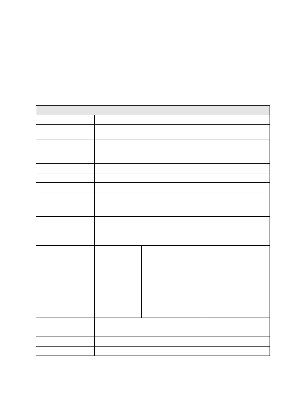
Table 1 Specifications - General
Physical
Weight 45 lb. (20.5 kg) net
Enclosure
Gear Train
Mechanical Stops To prevent over-travel.
Operating Temperature -30 °C to +75 °C (-20 °F to +170 °F)
Storage Temperature -40 °C to +93 °C (-40°F to +200 °F)
Relative Humidity 0-99 % R.H. noncondensing, over the full op erating temperature range.
Scale 0 to 100 % corresponding to full crank arm travel.
Crank Arm
Output Shaft
Output Torque/Full
Travel Stroking Time
Rotation 90 degrees between 0 and 100% on scale, limited by mechanical stops.
Precision-machined Aluminum alloy casting, finished i n light gray powder coat
epoxy.
Alloy steel, high efficiency steel spur gear primary train. Precision ground, self
locking/self releasing worm gear final mesh.
Adjustable radii (1 7/16" to a maximum of 5"). Position adjustable through 360°
rotation. Optional 12” crank arm adjustable 0 – 12” radii.
1" diameter, 1 1/2" long is standard on 10261S, 10262S, 10264S, 10266S, 10267S,
and 10268S.
1" diameter, 2" long is standard on 10263S, 10265S and 10269S optional on other
models.
Model #
10261S
10262S
10264S
10266S
10267S
10268S
10269S
10263S
10265S
Torque
Lb-ft N-M
10 15
20 27
40 55
60 80
40 55
80 110
150 200
200 270
300 400
Output Shaft Speed, sec/90
@60Hz @50Hz
10 12
20 24
40 48
60 72
20 24
40 48
60 72
40 48
60 72
°
Direction of Rotation Field programmable via local display and keypad.
Manual Handwheel Provides a means of positioning the actuator in the event of a power failure or set-up.
Lubrication Texaco Starplex 2 EP Grease
Revision 5 10260S HercuLine® Actuator Installation, Operation and Maintenance Manual 7
7/07
Page 18
2. Specifications - Technical and Operating Specifications
Electrical
Mains Supply
120 Vac single phase, 50 or 60 Hz
240 Vac single phase, 50 or 60 Hz
Motor
Instant start/stop, non-coasting, non-burnout, continuous duty permanent magnet
synchronous induction motor. Can be stalled up to 100 hours without damage.
Motor Current = No load = full load = locked rotor
Model No.
10261S, 62S, 64S,
66S
10263S, 10265S
120 V, 50/60 Hz
0.4 A (48 VA)
1.0 A (120 VA)
0.8 A (96 VA)
240 V, 50/60 Hz
0.3 A (72 VA)
1.0 A (120 VA)
0.3 A (72 VA)
10267S, 68S, 69S
Fuses
Wickmann USA #373-1160-0-41: 1.6 Amp Fast (2)
(Motor drive control)
Loss of Power Stays in place.
Local Auto - Manual
Allows local manual and automatic operation of the actuator. (Optional Feature)
Switch
Limit Switches Standard - Two SPDT end of travel limits.
Auxiliary Switches Optional - SPDT switches rated (10 A at 125 Vac, 5 A at 250 Vac).
Relays Optional - Up to 4 SPDT switches rated (5 A at 125 Vac, 2.5 A at 250 Vac).
Installation Category
(Overvoltage Category)
Category II: Energy-consuming equipment supplied from the fixed installation.
Local level appliances, and industrial control equipment. (EN 61010-1)
Pollution Degree
Pollution degree 2: Normally non-conductive pollution with occasional conductivity
caused by condensation. (ref. IEC 664-1)
Certifications
CE Compliance Optional
CSA/UL Optional
NEMA 4 Optional
Torque Settings of Crank Arm Bolts
Clamp Bolt Standard Arm (p/n 087449) (1 7/16 to 5 in. adjustment): 85 lb-ft.
Optional Long Arm (p/n 154007) (0-12 in. adjustment): 85 lb-ft.
Rod End Bolt Standard and long arms: 30-35 lb./ft
8 10260S HercuLine® Actuator Installation, Operation and Maintenance Manual Revision 5
7/07
Page 19
Specifications - Actuator with Digital Electronics
Input Signals Analog: 0/4 to 20 mA
(With supplied shunt resistor for current range: 250 ohms ±0.1 %
Part Number: 070756)
0/1 to 5 Vdc
0 to 10 Vdc
Digital: Modbus RTU RS485 (Remote setpoint)
2. Specifications - Technical and Operating Specifications
Electrical
Input Impedance
Input
0/4 to 20 mA
1 to 5 Vdc
Input
Characterization
Provides characterization of the input signal.
Selections are Linear, Square Root or Custom – Equal %, Quick Opening, User
Defined.
Sensitivity
0.2% to 5% of 90° span, proportional to deadband
Hysteresis Less than 0.4% of full scale.
Deadband
Repeatability
Voltage/ Supply
0.2% to 5.0% of 90° span, adjustable. Shipped at 0.5% span.
0.2% of 90° span
0.25% of span with +10/–15% voltage change
Stability
Temperature
Less than ±0.030% of span per degree C for 0 °C to 50 °C
Coefficient
Less than ±0.05% of span per degree C for –30 °C to 75
Zero Suppression 90 % of span
Input Filters Selectable spike and low pass filters.
Solid State Motor
Two triac switches for clockwise or counterclockwise motor operation.
Control
Input Impedance
250 ohms
10 M ohms
°C
Fail-safe Operation If input signal exceeds configured input range. Selectable and adjustable.
Feedback Ssignals
0 to 20 mA, or 4 to 20 mA
0 to 5 Vdc, or 1 to 5 Vdc with 250 ohm resistor ± 0.1 %
0 to 16 Vdc with 800 ohm resistor ± 0.1 %
Slidewire Emulation
Provides output voltage ratiometric to shaft position and potentiometric to supply
voltage (1-18 Vdc) without a slidewire. Emulates a 100 to 1000 ohm slidewire. 10 mA
output maximum
Digital Input Contact closure: 5 Vdc provided by actuator.
Power Isolation Input and output signals are isolated from power.
Load Requirement
Current Out, - 0 to 1000 Ω
(4-20)
Diagnostics
Self-test diagnostics of RAM, SEE memory, Configuration and Calibration at power up.
Operation statistics recorded for predictive maintenance. See Maintenance Set Up
Group.
Revision 5 10260S HercuLine® Actuator Installation, Operation and Maintenance Manual 9
7/07
Page 20
2. Specifications - Technical and Operating Specifications
Specifications – Local Display and Keypad
Display
Display Design
LED indicators Six single LEDs provide actuator status and alarm indications.
Display Operating
Temperature
Storage Temperature –40 °C to +93 °C (–40 °F to +200 °F)
Keys
Multi-segment LED displays that provide up to ten alphanumeric characters. Display
arrangement consists of two rows:
st
1
row (Upper display) – four characters
2nd row (Lower display) – six characters.
–30 °C to +50 °C (–20 °F to +122 °F)
Automatically shuts off when operating temperature exceeds +50 °C
Keypad
Six single pushbutton keys allow access to all status displays and set up group
parameters.
See 4. Set Up and Calibration Procedures (page 28) for detailed information on display and keypad fu ncti on s .
Specifications – Communications
Display
Modbus
Communications
Option
RS 485 Serial Communication, Modbus RTU Protocol
Connection Twisted pair cable with shield
Maximum loop length 600 meters (2000 feet)
Communication Mode Half duplex
Baud Rate 2400, 4800, 9600, 19.2K
HART
Communications
HART 5 an HART 6
10 10260S HercuLine® Actuator Installation, Operation and Maintenance Manual Revision 5
7/07
Page 21
Model Selection Guide
_-_
_-_
The following 10260 Smart Actuator models are covered in this manual. You can verify the model
description of your actuator by comparing the model number stamped on the top cover identification plate
with the following tables in this model selection guide.
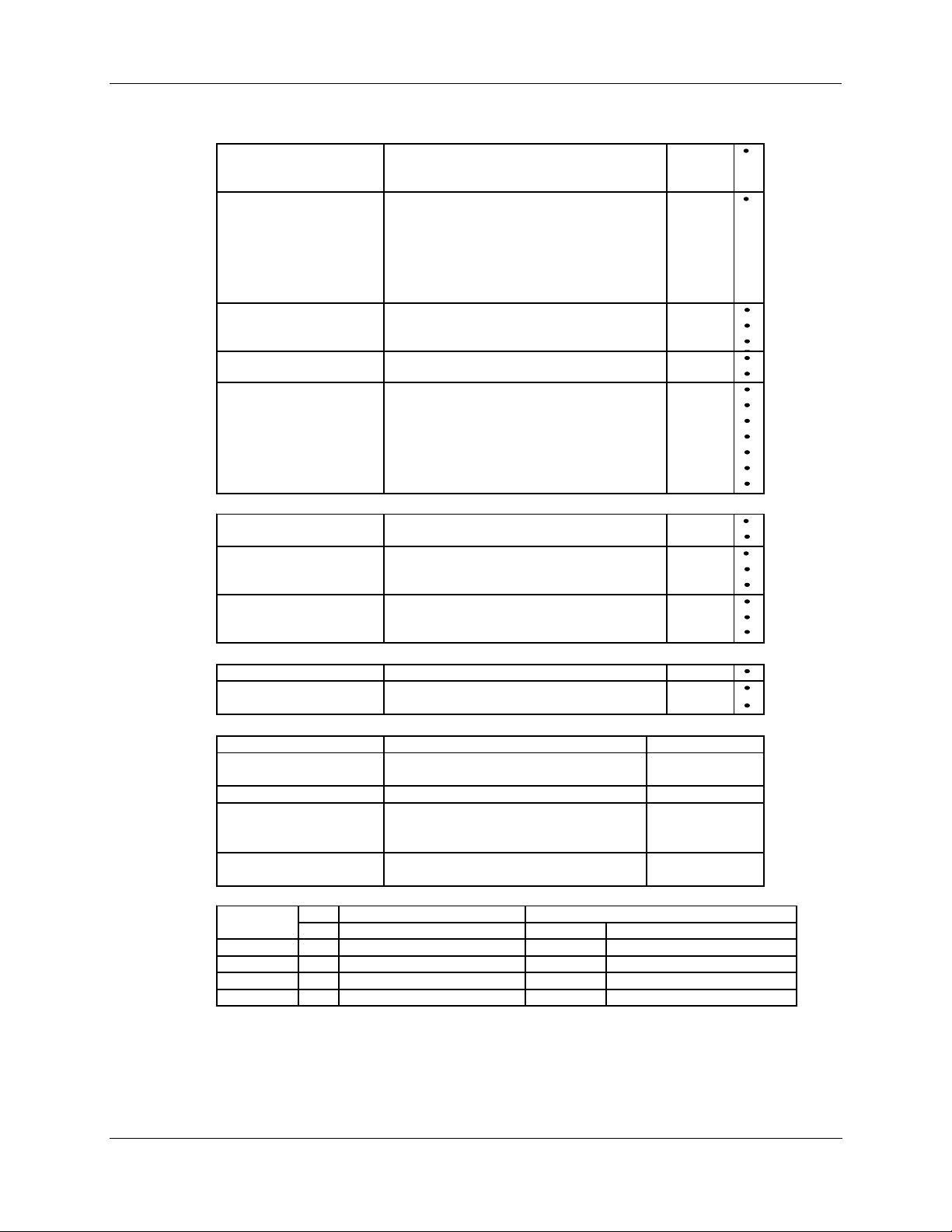
Instructions
Select the desired key number. The arrow to the right marks the selection available.
Make the desired selections from Tables I thru VIII using the column be low the arrow.
A dot ( ) denotes unrestricted availability.
Key Number I II III IV V VI VII VIII
_ _ _ _ _ _-
_ _ -_ _ _ -
2. Specifications - Model Selection Guide
-_ _ _ _ _ -_ _ _ -_ _
KEY NUMBER - Torque and Speed
Output Torque
(lb. - ft.) (N - M)
10 (15) 10 12 10261S
20 (27) 20 24 10262S
40 (55) 40 48 10264S
60 (80) 60 72 10266S
40 (55) 20 24 10267S
80 (110) 40 48 10268S
150 (200) 60 72 10269S
200 (270) 40 48 10263S
300 (400) 60 72 10265S
TABLE I - POWER SUPPLY - SINGLE PHASE
120 VAC 60 Hz Single Phase 120 VAC 60Hz Motor 1
120 VAC 50 Hz Single Phase 120 VAC 50Hz Motor 2
220/240 VAC 60 Hz Single Phase 220/240 VAC 60Hz Motor 3
220/240 VAC 50 Hz Single Phase 220/240 VAC 50Hz Motor 4
TABLE II - ANALOG INPUT/OUTPUT SIGNALS
Input
Full Travel Stroking - Time in Seconds
60 Hz 50 Hz
4-20 mA, 0-20mA (
1-5 Vdc, 0-5 Vdc, 1-10 Vdc, 0-10Vdc
)
Selection Availability
0 _ _
Output No Analog Position Output _ 00
4-20 mA, 0-20mA (
Slidewire Emulation _ 40
TABLE III - SWITCH AND RELAY OUTPUTS (2 mech end-of-travel limits standard)
Auxiliary Switches None 00 _
and 2 Aux. SPDT Switches 20 _
Relay Outputs 4 Aux. SPDT Switches 40 _
2 Aux. + 2 Programmable Relay Outputs 22 _
2 Programmable Relay Outputs 02 _
4 Programmable Relay Outputs 04 _
Auto/Manual Switch None _ _ 0
One Auto/Manual Switch with Out-of-Auto Contact _ _ 1
TABLE IV - CONFIGURATION INTERFACE
Remote
Local Integrally mounted local display/keypad interface 1
TABLE V - COMMUNICATIONS/PROTOCOL
Modbus RTU RS485 RS-485 Modbus compliant - standard with EEU 0
HART HART Communications Pro tocol 2
(Note 1)
None - requires HercuLink
1-5 Vdc, 0-5 Vdc, 1-10 Vdc, 0-10Vdc
TM
)
_ 20
0
Revision 5 10260S HercuLine® Actuator Installation, Operation and Maintenance Manual 11
7/07
Page 22
2. Specifications - Model Selection Guide
TM
TABLE VI - OPTIONS
Shafts Standard 0 _ _ _ _
Projecting Scale None _ 0 _ _ _
Crank Arm 5 Inch Standard _ _0 _ _
Rod Adapter None _ _ _ 0 _
Linkage Kits None _ _ _ _ 0
TABLE VII- OPTIONS
Weatherproof Weatherproof 0 _ _
Approvals
Tagging None _ _ 0
TABLE VIII - FACTORY OPTIONS
Special Manuals No Special Options (US Manual Standard) 0 _
Other None _ 0
ACCESSORIES
Handheld Configuator
(Note 3) Battery powered 232/485 converter w/cable
HART Turk Cable for Handheld Connection
Rod Adapters 5/8 Inch 083338
Crank Arm 5 Inch Standard
RESTRICTIONS
Restriction Available Only With Not Available With
Letter Table Selection Table Selection
b
c
d
e
VI X0XXX Key Number 10263A, 10265A, 10269A
VI 0X100 Key Number 10263A, 10265A, 10269A
VI 050XX, 060XX, 051XX, 061XX Key Number 10263A, 10265A, 10269A
VI X0XXX NANA
5 Inch Extension 1 _ _ _ _
3 Inch Extension
3 _ _ _ _
3/4 Inch Shaft Coupling _ 1 _ _ _
3/4 Inch Shaft Coupling, CCW to Open _ 2 _ _ _
1 Inch Shaft Coupling _ 3 _ _ _
1 Inch Shaft Coupling, CCW to Open _ 4 _ _ _
CW to Open, No Coupling _ 5 _ _ _
CCW to Open, No Coupling
_ 6 _ _ _
None _ _ 1 _ _
12 Inch
_ _2 _ _
3/8 Inch _ _ _ 1 _
12 to 16 Inch Turnbuckle Kit _ _ _ _ 1
16 to 20 Inch Turnbuckle Kit _ _ _ _ 2
20 to 24 Inch Turnbuckle Kit _ _ _ _ 3
1 Inch Pipe Kit _ _ _ _ 4
1.5 Inch Pipe Kit _ _ _ _ 5
2 Inch Pipe Kit
NEMA4/IP66
_ _ _ _ 6
1 _ _
None _ 0 _
UL / CSA _ 1 _
CE
Linen
Stainless Steel
(Note 2)
(Note 2)
Certificate of Conformance _ 2
Description Part Number
HercuLink
Palm Software
7/16 Inch 083336
7/8 Inch 083339
12 Inch
_ 2 _
_ _ 1
_ _ 2
51452354-509
51452354-510
51452352-501
51309967-501
51452160-501
b
e
c
c
c
c
d
d
Note 1:
Note 2: Customer must supply tagging information - Up to 3 lines, 22 characters per line.
Note 3:
HercuLink
running OS3.5 or higher and Palm serial cable are required if no display is selected.
Requires PDA manufacturer's serial interface cable.
TM
software (51452354-509), RS232/485 converter (51452354-510), customer supplied PalmTM PDA
12 10260S HercuLine® Actuator Installation, Operation and Maintenance Manual Revision 5
7/07
Page 23

Installation Overview
The procedures to install the 10260S actuator and place it in service require that you:
• Select a suitable location for installation. (See Installation Considerations below.)
• Mount the actuator securely.
• Install mechanical connections or linkage between control arm and final control element. Use HAL
software application to aid in mechanical installation.
• Make all electrical connections for actuator according to local and national electrical codes.
• Power up actuator.
• Enter, verify and adjust set up parameters for proper operation.
• Adjust control arm linkage for accurate operation of final control element.
This section provides you with mechanical and electrical installation information required to mount and
connect the 10260S Smart Actuator to your specific application. Unpacking instructions, installation
consisderations, electrical and safety precautions also included in this section should be observed.
3. Installation - Installation Overview
3. Installation
Revision 5 10260S HercuLine® Actuator Installation, Operation and Maintenance Manual 13
7/07
Page 24

3. Installation - Before Starting
Before Starting
Unpacking
If there are visible signs of damage to the shipping container, notify the carrier and Honeywell
immediately.
If there is no visible damage, compare the contents with the packing list. Notify the carrier and Honeywell
immediately if there is equipment damage or shortage.
Please do not return goods without contacting Honeywell Applications Center in advance. The contact
number is 1-800-423-9883.
Installation Considerations
Mount the actuator in a location where it will be easily accessible for maintenance and for manual
operation by means of the handwheel. The exact location must be determined in accordance with the
linkage used.
It is important that the actuator be mounted securely to a solid foundation commensurate with the
maximum torque developed. Use studs or bolts that are as large as the foot mounting holes.
The following precautions should be taken when selecting an installation site.
• Shield the actuator from rain or snow unless the NEMA 4 option was selected.
• Allocate sufficient clearance around the actuator for the removal of all covers to permit inspection of
internal parts and to provide access to the handwheel.
• Use auxiliary shielding to protect the actuator from excessive heat or cold outside of the rating of the
Actuator and from cor rosive elements
• Ambient temperature should not exceed 170 °F (75 °C).
• The minimum low temperature limit is –20 °F (–30 °C).
Actuator Mounting
Install the 10260S actuator in a convenient location in any orientation. Firmly bolt the 10260S to a
mounting surface that will not distort when subjected to the torque stresses generated by the actuator. The
output shaft of the actuator should be parallel to the output shaft o f the driven de vi ce. Th e output s haft
crank arm is fully adjustable through 360°.
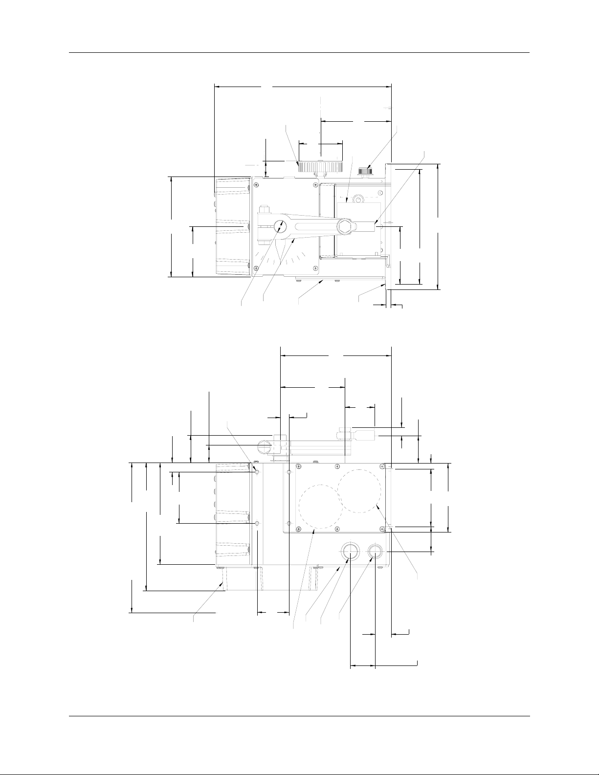
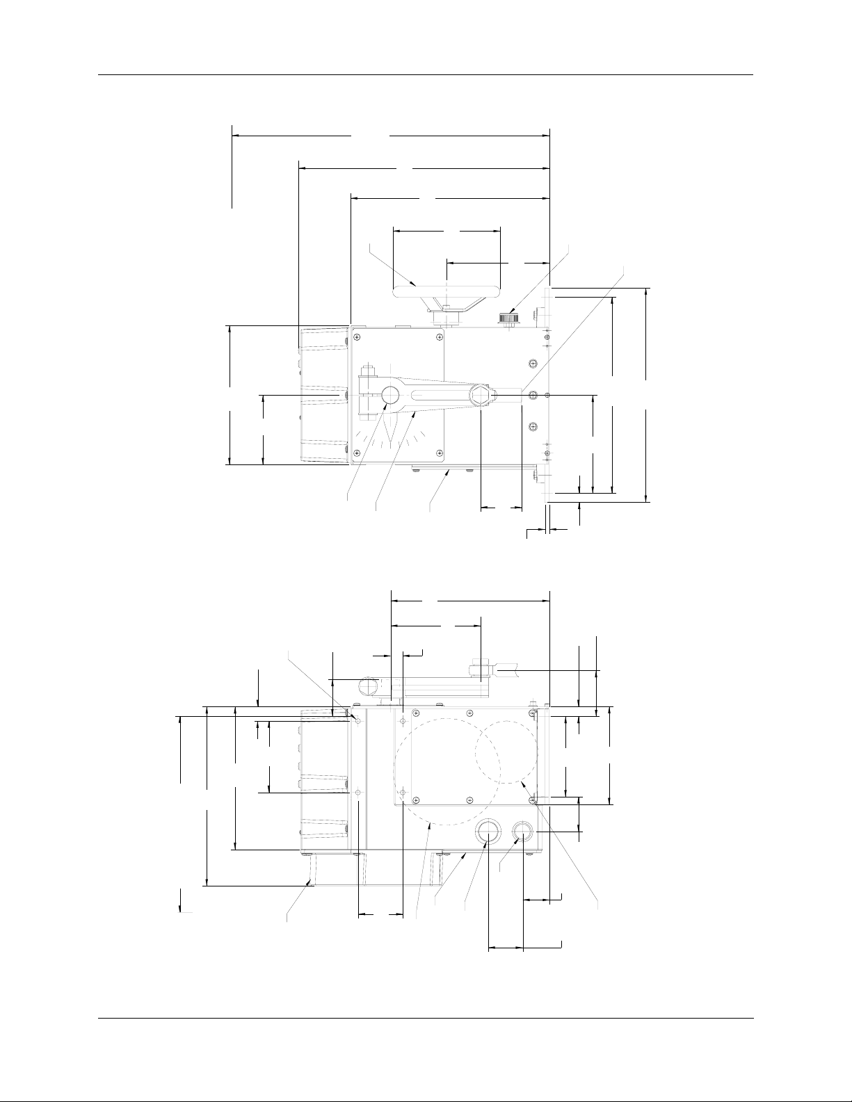
Outline Dimension Drawings
An outline and dimension drawing for actuator mounting is furnished with each unit.
are
provided here for reference.
Figure 3 and Figure 4
14 10260S HercuLine® Actuator Installation, Operation and Maintenance Manual Revision 5
7/07
Page 25
3. Installation - Actuator Mounting
]
7
.8
7
9
.
4
3
3
1
[
L
E
E
H
W
D
N
A
H
]
4
3
.
1
.6
4
1
[
]
.1
0
8
9
.8
1
7
[
]
0
.1
9
.
9
3
9
[
K
°
0
N
T
A
9
F
L
R
A
E
C
H
V
S
L
A
L
.
R
U
ia
T
F
]
d
0
.4
5
.0
2
1
T
F
A
H
D
S
R
T
A
D
F
D
E
A
L
N
H
A
R
S
T
U
S
N
]
K
6
.5
S
4
9
.3
3
6
1
[
2
0
1
]
1
3
.
1
4
.
5
2
[
]
5
.1
7
.
9
0
1
[
[
E
ID
.
P
S
D
H
)
C
.7
A
2
E
1
(
S
0
E
0
L
5
O
.
x
H
B
D
2
E
-
F
P
P
N
A
U
T
4
2
-
. 4
6
P
1
/
Y
5
T
.
ia
d
]
8
.9
3
5
.
8
3
[
G
R
IN
E
R
V
A
O
E
C
G
S
R
S
U
E
P
C
S
C
A
O
T
X
A
M
]
.8
3
7
0
.
2
5
1
[
]
9
.5
6
.
7
0
1
[
]
.7
0
9
.5
3
5
1
[
R
O
T
O
M
)
4
(
E
L
O
H
.
A
I
D
)
4
1
.
7
(
1
8
]
2
.
.1
3
9
1
.6
2
8
[
]
0
.4
3
.
8
2
5
[
H
C
IT
W
S
]
L
7
4
A
.
U
1
3
N
[
A
9
3
/M
2
.
O
1
T
X
U
A
7
4
.
4
D
B
A
2
E
-
R
F
H
N
U
T
0
P
2
E
-
2
E
/
D
1
]
.2
1
9
8
4
.
2
9
[
]
]
.5
.0
3
4
7
1
9
.
2
1
8
2
[
[
]
8
3
.7
.
9
0
[
]
2
.9
6
.
5
0
1
[
]
3
.6
0
.
1
2
5
[
4
.1
4
.
1
0
1
[
S
.
S
N
E
.
C
E
IO
S
C
D
T
I
IT
N
A
S
S
L
E
N
O
I
L
M
P
E
T
A
Y
T
S
H
N
T
U
.
A
J
A
IN
D
E
T
N
U
O
M
E
B
N
A
C
R
O
T
A
:
U
S
T
E
C
T
A
O
.
N
1
R
E
N
D
E
C
O
A
V
N
D
D
O
A
E
N
C
R
T
A
A
A
D
E
G
C
R
L
N
A
O
I
C
L
O
C
E
I
B
S
T
I
V
L
A
R
M
A
U
E
A
N
I
Q
S
R
E
M
R
G
D
R
O
A
I
E
A
F
T
D
E
S
E
G
ID
R
H
N
V
E
I
T
V
O
R
I
F
R
O
O
W
. P
.
C
2
3
]
4
8
.
9
3
.
5
L
9
2
A
[
V
O
M
E
R
R
E
V
O
C
R
O
F
N
I
M
]
.4
3
2
6
.
2
6
4
1
[
1
0
.0
1
4
[
]
.6
4
1
9
.
0
7
2
[
]
0
.5
.5
3
2
6
R
E
V
O
C
S
S
E
C
C
A
[
O
D
T
.
R
L
R
A
E
E
O
E
)
V
B
H
F
O
L
E
W
C
A
R
D
(
S
IN
N
S
M
A
E
R
H
C
E
C
T
A
IT
U
E
IT
L
D
E
U
O
L
N
D
H
O
O
N
H
C
D
O
"
E
D
/4
P
C
E
"
P
3
P
1
A
P
R
T
R
A
O
O
T
F
F
]
.6
0
]
]
2
.3
0
4
.5
8
5
.
1
6
.3
4
1
3
[
5
1
[
,
S
6
6
2
]
4
.3
9
.9
4
1
[
R
.)
O
F
T
E
O
R
(
M
]
4
.4
2
1
.
3
1
[
]
2
.8
.9
8
1
4
[
0
, 1
S
S
4
9
6
6
2
2
0
0
1
, 1
,
S
S
2
8
6
6
N
2
2
0
0
O
I
1
T
,
, 1
A
S
S
L
7
1
L
6
6
A
2
2
T
0
0
1
S
: 1
N
I
S
L
S
E
0
6
D
2
O
0
M
1
Figure 3 Outline and Dimensions of Herculine Models 10261S, -62S, -64S, -66S, -67S, -68S,
and -69S Actuators
Revision 5 10260S HercuLine® Actuator Installation, Operation and Maintenance Manual 15
7/07
Page 26
3. Installation - Actuator Mounting
R
E
V
L
]
O
A
C
0
V
.0
0
1
O
.
R
8
5
M
O
3
1
E
F
[
R
N
I
M
]
2
.1
0
6
.
5
4
3
1
[
]
9
0
.9
1
1
.
8
1
2
L
E
E
H
W
D
N
A
H
]
.1
0
8
8
.
9
7
1
[
]
0
.1
9
9
.
9
3
[
D
T
E
L
F
K
A
R
N
H
U
A
N
S
R
K
C
.
L
ia
]
L
d
U
0
.4
F
0
5
.
2
E
ID
.
S
P
H
D
C
)
A
7
.
2
E
1
S
(
E
0
L
0
O
5
x
H
D
B
2
E
-
P
F
P
N
A
U
T
4
4
2
.
6
P
1
Y
/
T
5
]
2
1
8
.5
.
0
0
2
[
1
[
D
R
T
A
F
D
A
N
H
A
S
T
S
]
3
.1
1
4
.
5
2
[
1
[
]
4
.
0
2
0
.
5
6
1
[
°
0
9
L
E
V
A
R
T
O
T
G
R
IN
E
R
V
A
O
E
C
G
S
R
S
U
E
P
C
S
C
A
]
.4
8
5
8
2
.
2
8
[
]
.0
4
8
0
.
2
5
1
[
]
9
.5
6
7
.
1
0
[
]
.0
5
6
7
.
4
5
1
[
]
3
.1
1
.
4
2
5
[
5
2
.
0
H
C
T
I
W
S
L
A
U
N
A
M
/
O
T
U
A
0
5
.
]
4
.
6
[
0
6
5
.
0
)
7
4
.
1
3
(
9
3
2
.
1
X
D
A
B
2
E
-
R
F
H
N
T
U
0
P
2
E
E
2
/
D
1
]
0
.4
0
9
0
.
7
0
1
.
2
1
2
[
1
]
.7
0
9
5
.
3
5
1
[
]
.7
2
1
[
]
5
.6
1
4
.
]
5
2
[
.1
4
1
[
S
.
S
E
N
E
C
IO
.
D
C
.
I
S
IT
A
R
S
T
S
L
E
N
O
L
IN
V
E
A
P
E
O
M
Y
H
T
C
T
N
A
S
T
S
A
U
N
E
S
J
C
E
O
D
IN
N
C
D
A
D
A
C
E
E
D
R
A
T
T
A
N
A
D
N
E
A
C
R
U
L
O
A
G
O
C
N
O
L
I
E
M
B
T
E
IS
IC
L
A
V
M
B
A
U
E
A
N
N
Q
I
S
R
A
E
M
R
G
D
C
R
O
A
IA
R
E
F
T
O
E
D
S
T
D
E
G
I
R
A
H
:
V
E
IN
U
T
S
O
V
T
IR
E
F
R
C
O
T
O
P
. W
O
.
. A
C
3
2
1
N
]
.8
4
0
3
[
]
.6
0
1
0
.
0
4
1
[
]
7
9
.0
3
.9
0
7
2
L
A
V
O
M
E
R
R
E
V
O
C
R
O
F
N
I
M
]
3
.4
6
.
2
6
2
1
4
[
[
]
9
4
.8
0
.
4
0
5
1
2
[
R
O
.
F
IT
E
U
L
D
O
N
H
O
]
0
.5
5
.
3
2
6
S
R
S
E
E
V
C
O
C
C
A
[
O
D
T
R
R
A
L
E
O
E
V
E
B
)
O
H
L
F
C
A
E
W
S
D
IN
(R
S
N
M
E
A
R
C
H
E
C
T
A
D
C
"
E
IT
E
P
/4
U
L
3
P
D
O
A
N
T
H
O
D
C
E
"
P
1
P
R
A
O
T
F
]
.3
0
4
5
.
1
4
1
[
]
9
.7
4
7
.
3
1
[
]
2
.8
9
.
8
1
4
[
]
,6
0
9
5
.
3
5
1
[
S
]
4
.3
9
.
9
1
4
[
R
)
O
F
T
E
O
(R
M
5
6
2
0
1
N
D
N
IO
A
T
A
S
L
3
L
6
2
A
0
T
1
S
:
S
IN
L
S
E
0
D
6
2
O
0
M
1
Figure 4 Outline and Dimensions of Herculine Models 10263S and 10265S Actuators
16 10260S HercuLine® Actuator Installation, Operation and Maintenance Manual Revision 5
7/07
Page 27
Mechanical Installation
Linkage Set-up
Many applications require the use of a linkage assembly and often the final control element does not have a
linear torque curve. The 10260S Actuator linkage can be set up to achieve an optimal delivered torque
distribution for specific applications. To assist with linkage design, Honeywell offers a linkage analysis
software application (HAL). The software c an be or dered as P/N 51197910-001.
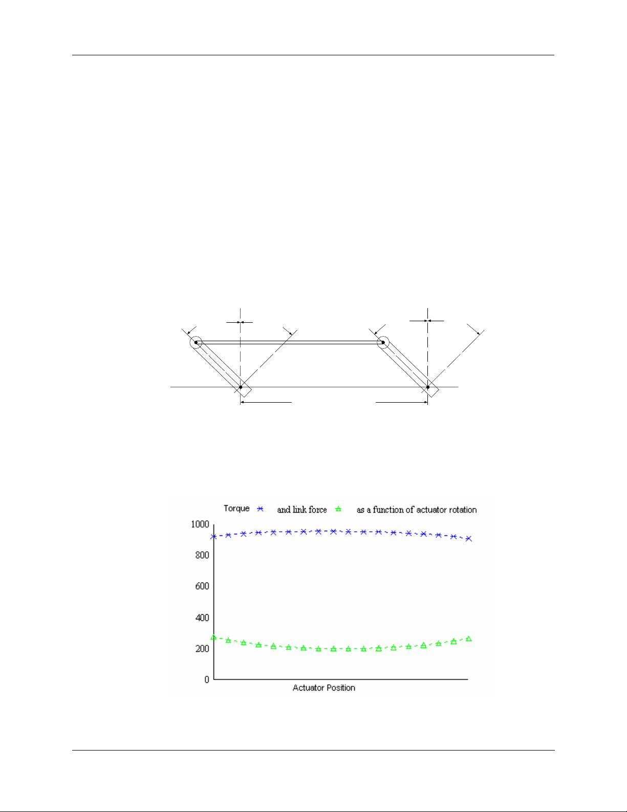
Constant Torque Linkage
A constant torque linkage is employed when it is desired to provide a linear torque profile throughout the
full range of final control element travel. In this situation, the actuator and driven crank arms will be set-up
proportionally with respect to each other.
pr
ofile and Figure 6 shows the resultant profile.
3. Installation - Mechanical Installation
Figure 5 shows a general linkage setup to achieve a linear torque
Vertical
Centerline
45° 45°
Vertical
Centerline
45° 45°
Linkage
Start Stop Close Open
Drive Unit
Crank Arm
Figure 5 Constant Torque Linkage
Horizontal Offset
Damper
Crank Arm
a/n 23199
Figure 6 Constant Torque Profile
Revision 5 10260S HercuLine® Actuator Installation, Operation and Maintenance Manual 17
7/07
Page 28
3. Installation - Mechanical Installation
Variable Torque Linkage
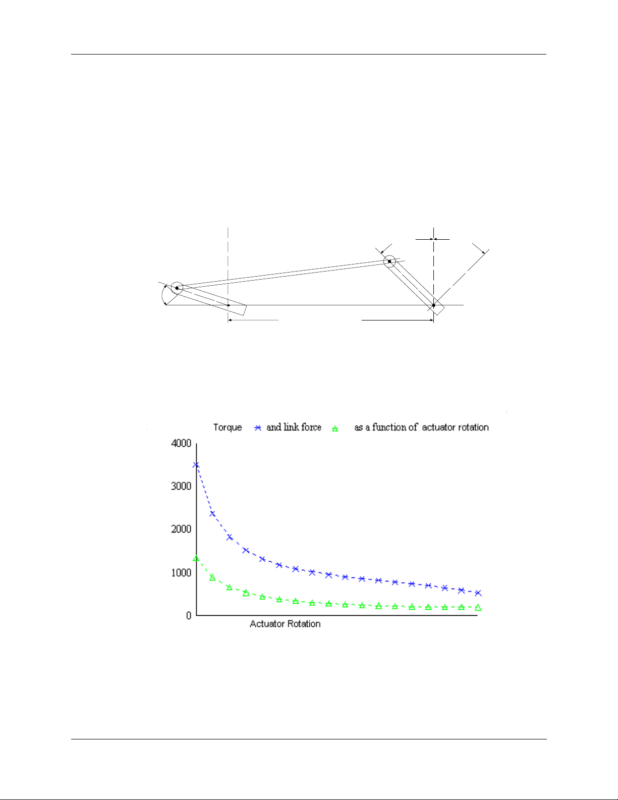
A variable torque linkage is employed when it is desired to provide a non-linear torque profile throughout
the full range of final control element travel. In this general situation, the actuator and driven crank arms
will be set up to provide a higher torque for seating or unseating the final control element.
eneral linkage setup to achieve a non-linear torque profile and Figure 8 shows the resultant profile. Note
g
at this linkage can be characterized in many different ways by varying start angles and rotation
th
requirements of both the Actuator Crank Arm and the Driven Arm.
Figure 7 shows a
Vertical
Centerline
Vertical
Centerline
45° 45°
Actuator
Linkage
Crank Arm
Close Open
5°
a/n 23200
Horizontal Offset
Damper
Crank Arm
Figure 7 Variable Torque Linkage
Figure 8 Variable Torque Profile
18 10260S HercuLine® Actuator Installation, Operation and Maintenance Manual Revision 5
7/07
Page 29
3. Installation - Mechanical Installation
Turnbuckle Linkage Kits (See Section 8 for available Kit numbers)
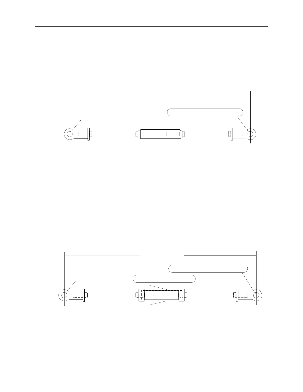
Turnbuckle linkage kits are available from Honeywell and are used where short lengths are required. The
lengths range from 12 to 24 inches and refer to the rod end center-to-center distance. These kits include the
turnbuckle, load rod end (left-hand thread), connecting rods and locking nuts. See
d end (right-hand thread), nut and bolt are supplied with the actuator. The nut and bolt needed to connect
ro
the rod end to the load are supplied by the customer. Kits can be ordered with the Actuator via Table VI of
the Model Selection Guide or separately as identified in section 8 of this manual.
12 to 24 inches
Figure 9. The actuator
Rod end, nut and bolt are
supplied with the actuator
1/2"-20 right-hand threads
Customer supplied nut and bolt
-20 left-hand threads
1/2"
Figure 9 Turnbuckle Linkage Kit
Pipe Linkage Kits (See Section 8 for available Kit numbers)
Pipe linkage kits are available from Honeywell and can be used for linkage lengths from 24 to 120 inches
(60 to 305 cm). The kits include the mechanical pipe couplings, load rod end (left-hand thread), connecting
rods and locking nuts . See
. T
he actuator rod end (right-hand thread), nut and bolt are supplied with the actuator. The customer must
Figure 10 Pipe Leakage Kit
supply a piece of schedule 40 pipe * (both ends with right-hand NP threads) and a nut and bolt to connect
the rod end to the load. Pipe linkage kits can be ordered with the Actuator using Table VI of the Model
Selection Guide or separately as identified in Section 8 in this manual.
a/n 23201
24 to 120 inches
Rod end, nut and bolt are
supplied with the actuator
1/2"-20 right-hand threads
Customer supplied pipe*
Customer supplied nut and bolt
1/2"-20 left-hand threads
* cut to size
with
standard NPT both ends
*Pipe length = Overall linkage length minus (-) 17 inches (43 cm).
a/n 23202
Figure 10 Pipe Leakage Kit
Revision 5 10260S HercuLine® Actuator Installation, Operation and Maintenance Manual 19
7/07
Page 30
3. Installation - Mechanical Installation
Actuator Crank Arms
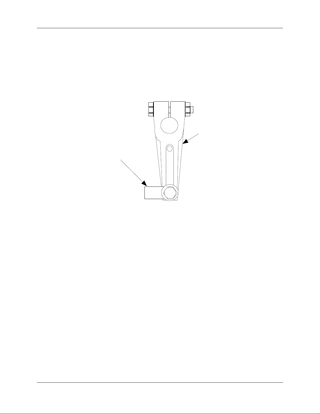
The 10260S Smart Actuator comes standard with a 5-inch crank arm (adjustable 1 7/16” to 5” radi us) a nd
there is an optional 12-inch crank arm that is adjustable from 0 to 12”. Part Number 154007
The 10260S Actuator crank arm uses a standard ½ inch rod end to compliment the turnbuckle and pipe
linkage kits. See
in
the Model Selection Guide.
Figure 11. For applications that use a link rod, a link rod adapter is available as an option
1/2" Ro d E nd
Crank Ar m
Figure 11 Standard 5-Inch Crank Arm
20 10260S HercuLine® Actuator Installation, Operation and Maintenance Manual Revision 5
7/07
Page 31
Projecting Scale Option
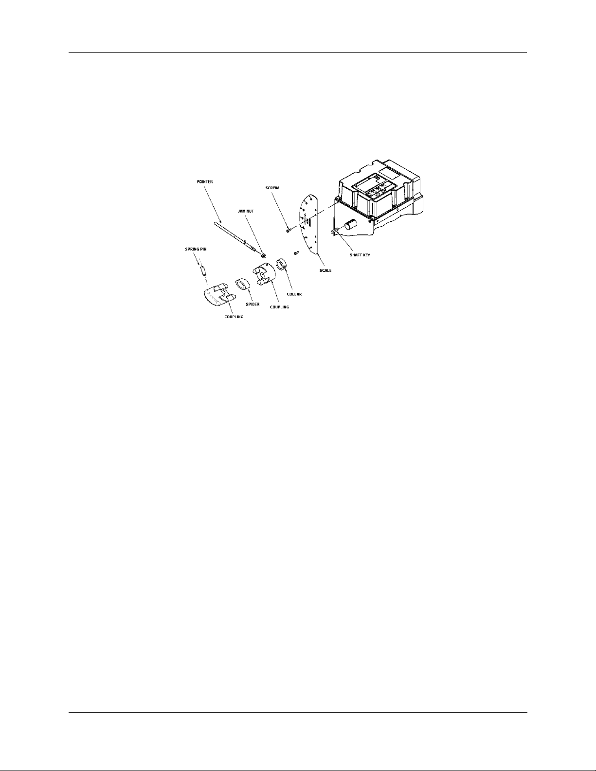
The projecting scale option is available for customers whose actuators are direct coupled so that it would be
impossible to read the standard scale on the actuator. The projecting scale is attached to the side of the
actuator enclosure and is readable from a distance. See
3. Installation - Mechanical Installation
Figure 12.
Figure 12 Projecting Scale Option Exploded View
Revision 5 10260S HercuLine® Actuator Installation, Operation and Maintenance Manual 21
7/07
Page 32
3. Installation - Electrical Installation
Electrical Installation
General Wiring Recommendations
WARNING
Only qualified personnel should perform wiring.
Wiring must conform to national and local electrical codes.
In general, stranded copper wire should be used. Unless locally applicable codes dictate otherwise, the
recommended minimum wire sizes in Table 2 should be observed.
Gage No. Description
14 Earth ground wire to common power supply.
18
Safety Precautions
WARNING
An external disconnect switch must be installed to break all current carrying conductors
connected to the actuator. Turn off power before working on conductors. Failure to observe
this precaution may result in serious personal injury.
Actuator Connections
WARNING
WARNING
While the unit is powered, a potentially lethal shock hazard exists inside the case. Do not open
the case while the unit is powered. Do not access the terminals while the unit is powered.
The 10260S actuator terminal connections for the field wiring are located behind the cover on the actuator
case as shown in Figure 2. Power and field wiring is brought into the
located on the side of the actuator case. The screw terminals for all customer connections are identified in
Table 3.
Table 2 Rec
Earth ground wire to single actuator. 120/240 V ac line leads. +24 V and common
signal leads.
The ground terminal must be connected to a reliable earth ground.
ommended Minimum Wire Size
actuator through two access holes
Fig
ure 13 shows the location of the terminal connections on the actuator terminal blocks. Desciptions for
power input, input and output signal connections are given in Table 3.
22 10260S HercuLine® Actuator Installation, Operation and Maintenance Manual Revision 5
7/07
Page 33

3. Installation - Electrical Installation
Revision 5 10260S HercuLine® Actuator Installation, Operation and Maintenance Manual 23
7/07
Page 34
3. Installation - Electrical Installation
Table 3 Actuator Terminal Connections
Connection
Terminal Numbers
and LABEL
Descriptions
See
Figure 13.
HOT L Hot wire for 120/240 Vac mains supply
NEUTRAL N - 3 Neutral wire for 120/240 Vac mains supply
PE Ground Ground wire connection for mains supply
AUTO/MANUAL
SWITCH CONTACT
4 – 20 INPUT 28 (-)
4 – 20 OUTPUT * 30 (-)
FEEDBACK 32
MODBUS
COMMUNICATION
HART
COMMUNICATION
DIGITAL INPUT 36 COM
SW1
10 – 11
29 (+)
31 (+)
33 (-)
34 (+)
35 SHIELD
28 (-)
29 (+)
37 INP
6 - 7 SW1 NC
9 SW1 COM
14 SW1 NO
Switch contact to indicate setting of actuator AUTO/MANUAL
switch. Switch is closed when actuator is “NOT-IN-AUTO”
Analog signal input from controller.
Analog signal output from actuator.
Feedback signal used in conjuction with 4 – 20 OUTPUT voltage
when using Slidewire Emulation.
Connection for RS485 Modbus loop wires.
HART communication is for 4-20 mA input only.
Customer’s contact closure.
End-of-travel limit switch 1 connections
SW2
SW3/RELAY1
SW4/RELAY2
24 10260S HercuLine® Actuator Installation, Operation and Maintenance Manual Revision 5
7/07
4 - 5 SW2 NC
8 SW2 COM
15 SW2 NO
16 NC
17 COM
18 NO
19 NC
20 COM
21 NO
End-of-travel limit switch 2 connections.
Auxiliary switch 3 or Relay 1 connections.
Auxiliary switch 4 or Relay 2 connections.
Page 35

3. Installation - Electrical Installation
Connection
SW5/RELAY3
SW6/RELAY4
Terminal Numbers
and LABEL
See
Figure 13.
22 NC
23 COM
24 NO
25 NC
26 COM
27 NO
Descriptions
Auxiliary switch 5 or Relay 3 connections.
Auxiliary switch 6 or Relay 4 connections.
Revision 5 10260S HercuLine® Actuator Installation, Operation and Maintenance Manual 25
7/07
Page 36
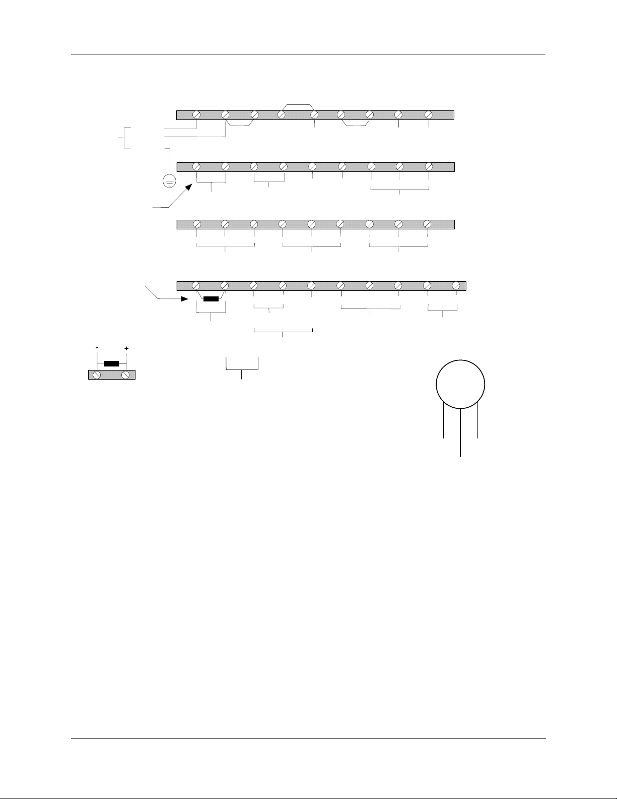
3. Installation - Electrical Installation
A
A
L
120V/240VAC
50/60 Hz
MAINS POWER
CLOSED WHE N
"NOT -IN-
HOT
NEUTRAL
UTO "
PE
UTO/MAN
SWITCH CONTACT
19
20
3 4N
INTERNAL
CONNECTIONS
21 2322
SW2
NC
141312
SW1
NO
6
SW1
NC
15 181716
SW2 NC
NO
24 2625
75
SW1
COM
SW3/RELA Y1
9
8
SW2
COM
NO
C
27
REMOVE R ESISTOR
FOR VOL TAGE IN PUT
RESI STOR T O BE M OUNTED
*
AT IN PUT OF CUSTO MER'S
RUMEN T
INST
SW4/RELAY
+
-
2 5 0
Ω
INPUT
4-20
COMMUNICATIONS
COMMUNICATIONS
C
2
-
4-20 OUTPU T
SLIDEWIRE EMULATION
+
+
-
-
*USE COPPER CONDUCTORS ONLY
HART
HART
CONNECTION
CONNECTION
SW5/RELAY 3
3129
+
FEEDBACK
*
CNO NC
SW6/RE LAY 4
33 343230
+
-
COMMUNICATION
SHIELD
NC
28
Figure 13 Actuator Terminal Connections
NO
CNO NC
37
3635
IN P
DIG ITA L INP UT
HART connection using
HART connection using
external Turck connector
external Turck connector
Auxiliary
Auxiliary
Connector
Connector
_
_
Brown
Brown
Black
Black
Black Wire Not Used
Black Wire Not Used
COM
+
+
Blue
Blue
1. Before running
actuator remotely
with a PDA &
HercuLink, first
disconnect any
master Modbus
device at terminals
shown (master
Modbus wires not
shown).
2. Ensure good connection to remaining
Modbus wires (shown).
Figure 14 Modbus terminals
26 10260S HercuLine® Actuator Installation, Operation and Maintenance Manual Revision 5
7/07
Page 37
Power Connections
The AC power supply input option is a Table I selection in the model selection guide. Depending on which
power supply selection is ordered for your actuator, wire the power input (MAINS POWER) as described
in Table 3 and Figure 13. Wiring must confrom to national
CE Wiring
The CE approval option is a Table IV selection in the model selection guide. When wiring the actuator
power input for CE approved units, you must also install a MOV assembly to the power input. MOV
assembly is ordered as a kit. See Section 8 for kit descriptions and part numbers.
Input Signal Connections
ATTENTION
Shielded and grounded cables are recommended.
0/4-20 mA Input Signals
For current signal input, use the 250 ohm resistor supplied across terminals 28 and 29 on the actuator
terminal block connections. Observing polarity, connect the signal input wires to terminals 28 and 29 of
the terminal block. See Figure 13.
3. Installation - Electrical Installation
and local electrical codes
0/1-5 Vdc and 0 to 10 Vdc Input Signals
For voltage signal input, remove the resistor from terminals 28 and 29 on the actuator terminal block.
Observing polarity, connect the signal input wires to terminals 28 and 29 of the terminal block.
Output Signal Connections
0/4-20 mA, 0/1-5 Vdc Feedback Signal Connections
ATTENTION
Shielded and grounded cables are recommended.
Actuator output is 0/4 to 20 mA analog signal. If a voltage input is required for customer devices, a range
resistor is needed at the device input. See
Table 3 and Figure 13 for more information.
Slidewire Emulator Connections
ATTENTION
Shielded and grounded cables are recommended.
Slidewire Emulation output option is a Table II selection in the model selection guide. If you ordered the
Slidewire output option for your actuator, it is set at the factory to provide an output that emulates 100 to
1000 ohm slidewires. For terminal block connections to the actuator, refer to
Table 3 and Figure 13.
Revision 5 10260S HercuLine® Actuator Installation, Operation and Maintenance Manual 27
7/07
Page 38
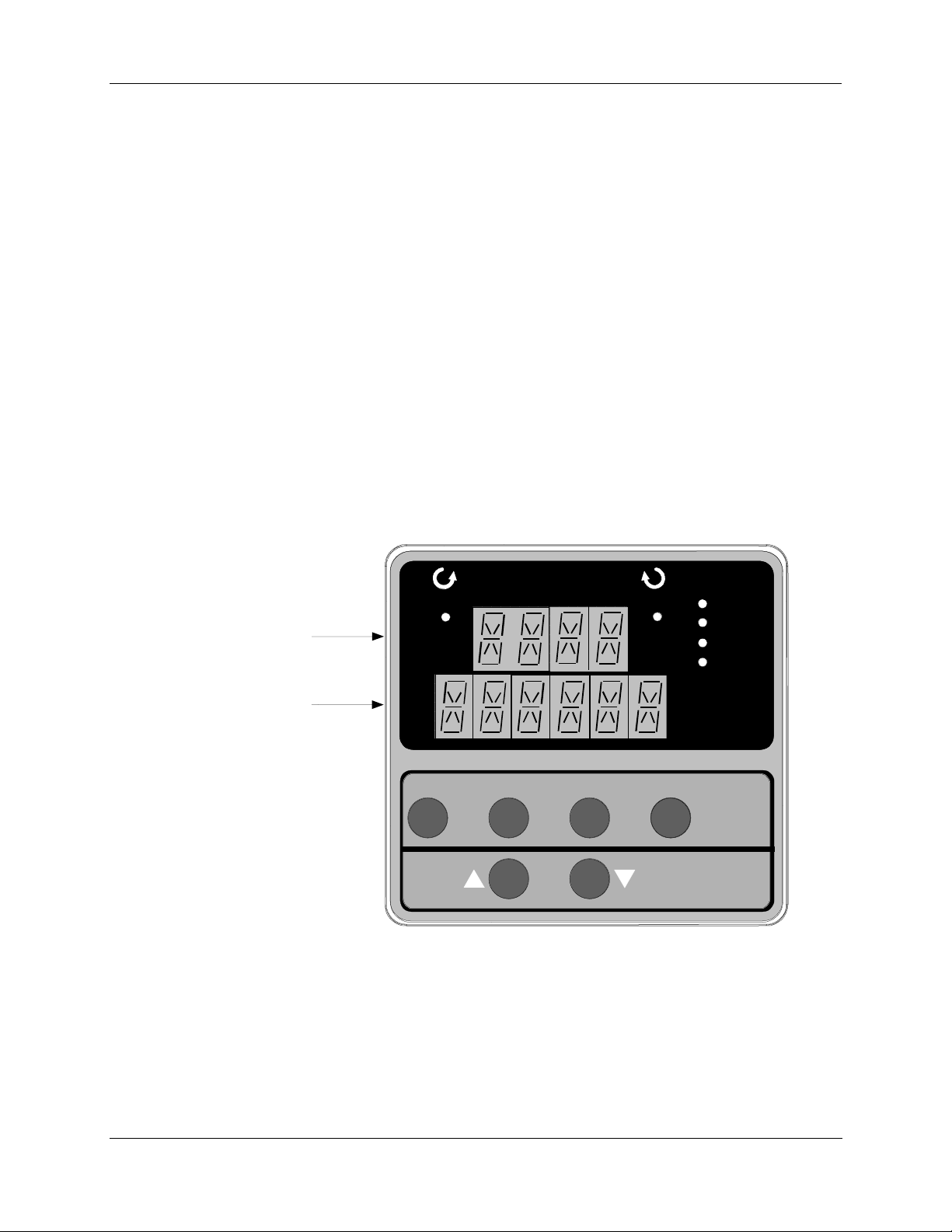
4. Set Up and Calibration Procedures - Overview
4. Set Up and Calibration Procedures
Overview
Once you have installed the 10260S smart actuator, you can verify, set or change certain operating
parameters. Set up is accomplished through use of the local display and keypad interface. Please keep in
mind that the unit is calibrated at the factory for your application and can be placed into service right out of
the box. Changing operating parameters may require recalibration of the actuator. This section details the
various operating parameters and functions of the actuator available using the local display and keypad
interface, and calibration procedures.
Local Display and Keypad
The alphanumeric display and keys on the keypad are the local operator interface for control, monitoring,
and configuration of the 10260S actuator. The display consists of a four character upper display and a six
character lower display. Six LEDs of various colors indicate actuator operating status. Directly below the
display are six keys that allow you to setup, monitor, and control the actuator locally, as well as call up
various operating parameters and configuration values on the display. Figure 15 shows the physical
feature
s of the display and keypad. Table 4 summarizes the various functions you can perform using the
key
s as well as descriptions of the status indicators.
STALLED
Upper Display
(Four Characters)
Lower Display
(Six Characters)
FUNCTIONSET UP
Figure 15 10260S Display and Keypad
MAN/AUTO
DISPLAY
ALARM
MANUAL
AUTO
28 10260S HercuLine® Actuator Installation, Operation and Maintenance Manual Revision 5
7/07
Page 39
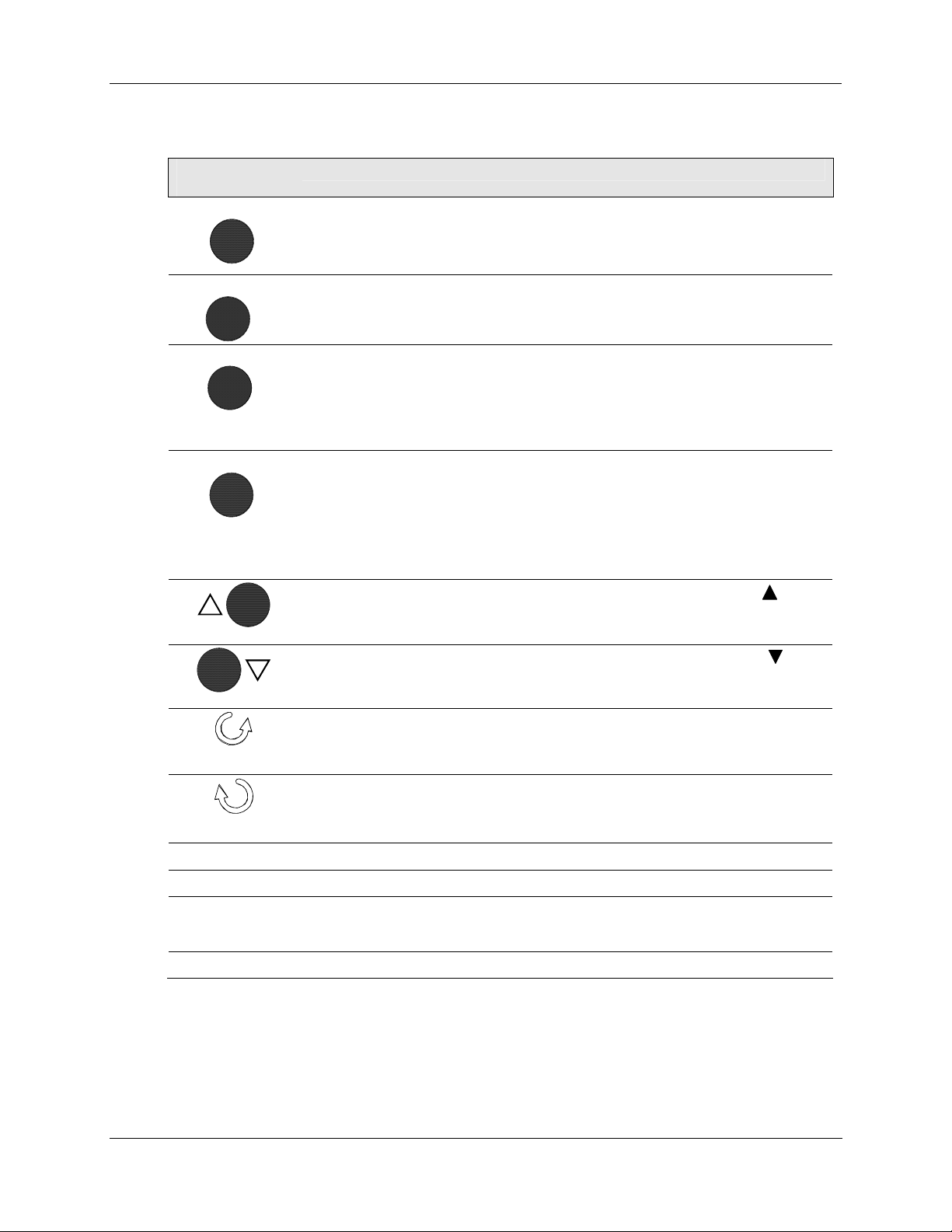
4. Set Up and Calibration Procedures - Local Display and Keypad
Table 4 Keypad Description
Key or
LED Indicator
SET UP
FUNCTION
MAN/AUTO
DISPLAY
☼
☼
☼ STALLED
☼ ALARM
☼ MANUAL
☼ AUTO
Places the actuator in the set up group select mode. Sequentially displays set up
groups and allows the FUNCTION key to display function parameters within the set
up group.
See for descriptions of the various options available in the set up groups.
Used in conjunction with the SET UP key to select the individual functions of a
selected configuration set up group.
Used during field calibration procedure.
Alternately selects:
MAN - Actuator is in Manual mode.
AUTO - Actuator is in Automatic mode.
NOTE: When in Manual mode the POS display is automatically selected so you
can use the up and down arrow keys to drive actuator motor manually.
Pressing this key repeatedly cycles through the operating parameters that can be
shown on the lower display.
INP – Input. Shows the value of the actuator input.
OP – Output. Shows the value of the actuator output
DE – Deviation. Shows deviation between in put value and actuator position.
POS – Position. Shows current actuator position.
Increases the configuration values shown on the display. Also shown as .
In manual mode and POSition display selected, pressing this key will drive actuator
motor in direction of increasing signal input.
Decreases the configuration values shown on the display. Also shown as
In manual mode and POSition display selected, pressing this key will drive actuator
motor in direction of decreasing signal input.
Indicates the movement of the actuator arm in the counterclockwise direction.
NOTE: Actuator rotation is the direction of the output shaft when facing the end of
the shaft and refers to the direction of rotation on increasing signal.
Indicates the movement of the actuator arm in the clockwise direction.
NOTE: Actuator rotation is the direction of the output shaft when facing the end of
the shaft and refers to the direction of rotation on increasing signal.
Indicates that the actuator has detected a motor stall condition.
Indicates a programmed alarm condition exists.
Indicates actuator is in manual mode. On solid when placed in manual mode from
the local display mode key. Blinks at a 1 sec rate when placed in manual mode
from the external drive switch.
Indicates actuator is in automatic mode.
Function
.
Revision 5 10260S HercuLine® Actuator Installation, Operation and Maintenance Manual 29
7/07
Page 40

4. Set Up and Calibration Procedures - Set Up Tips
Set Up Tips
Table 5 contains tips that will help you view, verify and enter the operating parameters more quickly. If
you can not change the parameters, check the status of the “ SET LOCK” parameter. Also some
parameters require that you enter a security password before you access or change the parameter value.
Function Tip
Table 5 Set Up Tips
Displaying Groups
Displaying Functions
Scrolling
Changing values quickly
Exiting Set Up mode
Timing out from
Set Up mode
Use the SET UP key to display and scroll through the set up groups. The
group titles are listed in the order they appear on the actuator display.
Use the FUNCTION key to display the individual function parameters
under each set up group. The prompts are listed in the order of their
appearance in each group. See Tables 8 through 19.
Pressing and holding the SET UP key will scroll through the set up
groups. However, when any set up group is displayed, you can scroll
through the set up groups twice as fast using the or key. When in
any set up group, hold the FUNCTION key in to scroll through the
function prompts within that group.
When changing the value of a parameter, you can adjust a more
significant digit in the upper display by holding in one key
and pressing the other
• The adjustment will move one digit to the left.
• Press the key again and you will move one more digit to the left.
To exit Set Up mode, press the DISPLAY key.
This returns the display to the same state it was in immediately preceding
entry into the Set Up mode.
If you are in Set Up (configuration) mode and do not press any keys for
thirty seconds, the actuator display will time out and revert to the mode
and display that was being used prior to entry into Set Up mode.
or key at the same time.
or key,
Set Up Groups
Pressing the SET UP key on the keypad provides access to the various set up groups and allows you to set
up operating parameters, (such as input types and alarms), calibrate the actuator’s inputs and outputs, set
communications, and check actuator status. Table 6 on the next page lists the set up groups that are
available
30 10260S HercuLine® Actuator Installation, Operation and Maintenance Manual Revision 5
7/07
by using the SET UP and FUNCTION keys on the keypad.
Page 41

4. Set Up and Calibration Procedures - Set Up Groups
Table 6 Set Up Groups
Set Up Group Title Pressing the FUNCTION Key Allows You to… For Details, See
SET
INPUT
SET
RELAYn
n = 1, 2, 3, or 4
SET
CUROUT
SET
COMM
SET
DIGINP
SET
DISPLA
CAL
INPUT
CAL
MOTOR
Select and set various parameters associated with the
input signal to the actuator.
Select relay functions. NOTE: Set Relay groups will
show on display only if relays are installed in the
actuator.
Select the output signal type of the actuator.
NOTE: Set Curout will show on display only if the
option was ordered.
Select communication parameters for remote control of
actuator when connected to a SCADA system.
Select the parameters for external digital input states.
Select and set parameters for the local display.
Calibrate input zero and span values.
Calibrate zero and span values for motor operation. Calibration
Table 8
Table 12
Table 13
Table 14
Table 15
Table 16
Calibration
Procedure,
Table 23
Procedure,
Table 24
CAL
CURENT
SET
LOCK
READ
STATUS
SET
DRVINF
SET
MAINT
CAL
POSOUT
Revision 5 10260S HercuLine® Actuator Installation, Operation and Maintenance Manual 31
7/07
Calibrate actuator output. Calibration
Procedure,
Table 25
Set or change security password. Enable or disable
security access to set up parameters and calibration
set up.
Display operating and alarm status. Display self-test
diagnostic results.
Display and/or set various parameters specific to the
actuator.
Display various operating statistics. Reset / Save
accumulated operating statistics
Use the display as an indicator, (in this case a
voltmeter) so you can verify the position sensor is
operating properly.
Table 17
Table 18
Table 19
Table 20
Table 21
Page 42
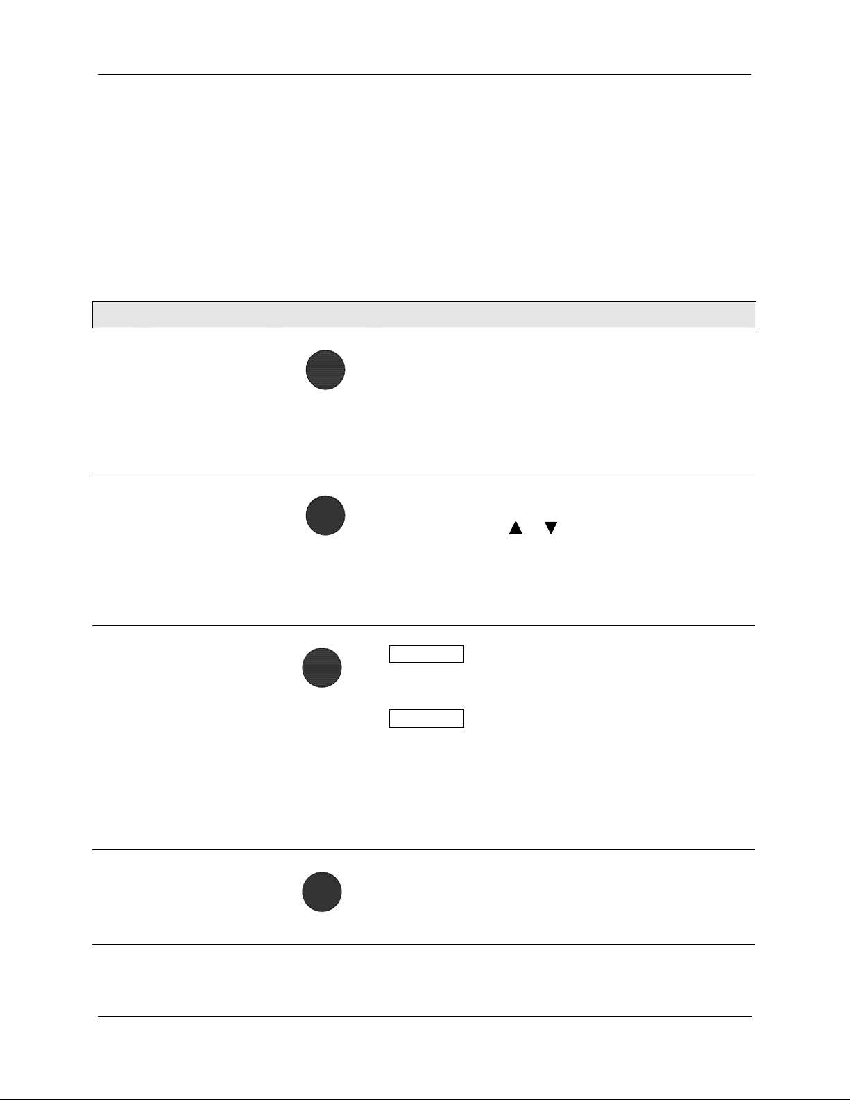
4. Set Up and Calibration Procedures - Set Up Procedure
Set Up Procedure
Each of the set up groups and their functions are either pre-configured at the factory or set to their default
values. Tables 8 through 19 list and describe the options available in each set up group. The following
procedure shows you the key press sequence to access any set up group or any associated Function
parameter. Make sure lock set up group “LOCK” function is set to “NONE” or “CAL.” Also some
parameters require that you enter a security password before you access or change the parameter.
You can use this procedure to access the set up groups and select all parameters.
Table 7 Set Up Procedure Using Display and Keypad
Step Operation Press Result
1 Enter Set Up Mode
2
3
Select any Set Up
Group
Select a Function
Parameter
SET UP
SET UP
FUNCTION
Upper Display = SET
Lets you know you are in the set up mode and a set up group
title is being displayed in the lower display.
Lower Display = INPUT
This is the first set up group you see when you press SET UP.
Successive presses of the SET UP key will display the other set
up group titles as listed in
You can a
groups in both directions.
Stop at the set up group title that describes the group of
parameters you want to configure. Then proceed to the next
step.
Upper Display
function prompt in the selected set up group.
Lower Display
set up group.
4-20
IN TYP
lso use the
Shows the current value or selection for the
Shows the first function prompt within the selected
Table 6.
or keys to scroll through the set up
Example display shows Input group function prompt “IN TYP”
and the selection. Note: The majority of the functions in the
actuator are displayed this way. Although there are several
functions where the displays are reversed. The function name is
in the top display and the value is in the bottom display.
4
32 10260S HercuLine® Actuator Installation, Operation and Maintenance Manual Revision 5
7/07
Select other
function parameters
FUNCTION
Successive presses of the FUNCTION key will sequentially
display the other function prompts of the selected set up group.
Stop at the function prompt that you want to change, then
proceed to the next step.
Table continued on next page ⇒
Page 43
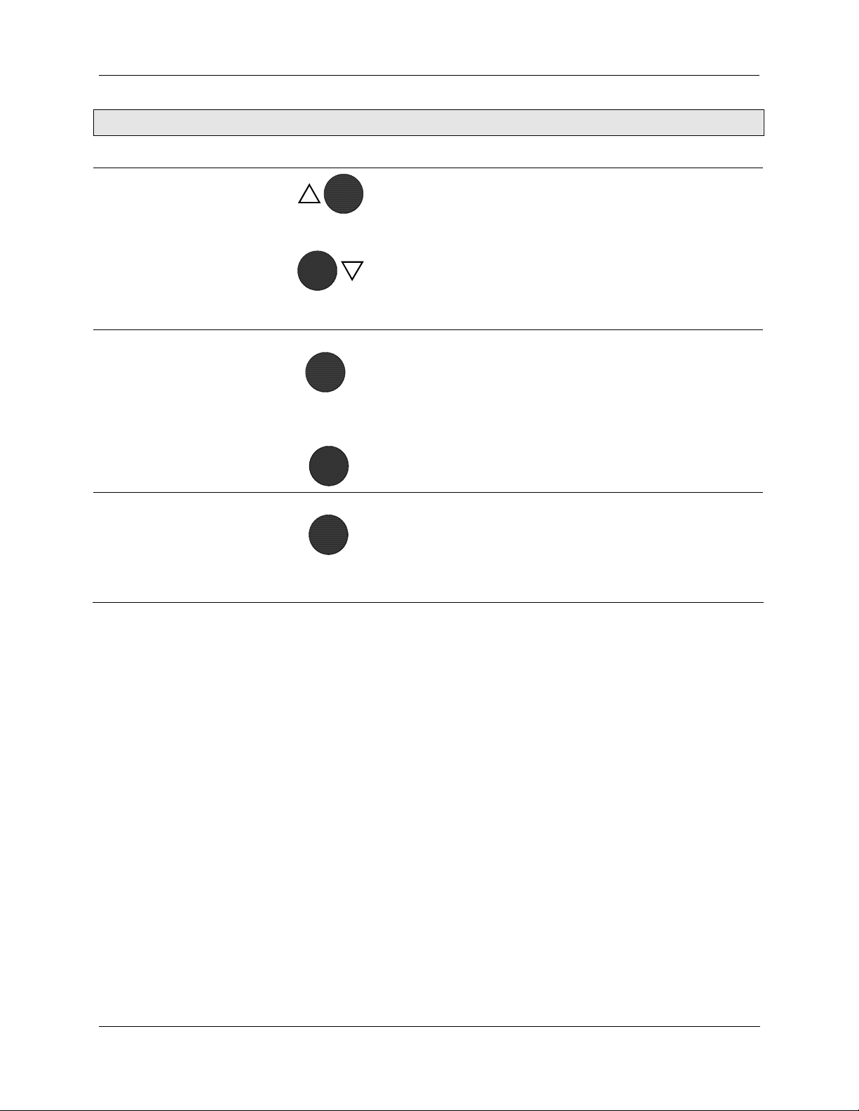
4. Set Up and Calibration Procedures - Set Up Procedure
Step Operation Press Result
5
Change the Value
or Selection
or
These keys increase or decrease the value, or display the next
available selection for the selected function prompt.
See Table 5, Set Up Tips for instructions to i
a value quickly.
Change the value or selection to meet your needs.
NOTE: If the display flashes, you are trying to make an
unacceptable entry, or the value on the display is at its range
limit. The display may also show “KEYERR” (Key error).
ncrease or decrease
6
Enter Value or
Selection
7 Exit Set Up mode
FUNCTION
or
SET UP
DISPLAY
This key selects another function prompt.
This key selects another set up group.
NOTE: Pressing either key will cause the previously selected
value or selection to be entered into memory.
Exits set up mode and returns actuator to the same state it was
in immediately preceding entry into the set up mode. Any
changes you have made are stored in memory.
If you do not press any keys for 30 seconds, the display times
out and reverts to the mode and display shown prior to entering
the set up mode.
Revision 5 10260S HercuLine® Actuator Installation, Operation and Maintenance Manual 33
7/07
Page 44

4. Set Up and Calibration Procedures - Input Set Up Group
Input Set Up Group
Table 8 lists the parameters and selections available when the SET INPUT group is selected.
On the keypad and local display:
• Press the SET UP key to enter the Input Set Up group.
• Press the FUNCTION key to scroll through the prompts listed in the set up group.
• Press the or keys to view selections or change range settings.
Table 8 Input Set Up Group Parameters
Lower Display
Prompt
IN TYP
INP HI 10.0 to 100
INP LO
FILTYP
Upper Display
Selections or
Range of Setting
0.0 to 90.0 INPUT LOW RANGE VALUE in % is displayed.
4-20
0-20
1-5V
0-5V
0-10
R_SP
NONE
Parameter Definition
INPUT ACTUATION TYPE—This selection specifies the
signal type and range you are going to use for the actuator
input. Be sure that the values configured for the high and low
range, alarm setpoint, etc. are within the measuring range
for the selected signal range.
4 to 20 mA
0 to 20 mA
1 to 5 Volts dc
0 to 5 Volts dc
0 to 10 Volts dc
Remote Setpoint (via communications)
NOTE: Changing the Input Actuation Type will restore the
actuator calibration to its factory values.
INPUT HIGH RANGE VALUE in % is displayed.
NOTE: You must set Input Low range to a value that is at
least 10% less than Input High range.
INPUT FILTER TYPE—Allows selection of a software digital
input filter to smooth the input signal.
SPIK
S+LP
LPAS
[default]
LPFILT *
34 10260S HercuLine® Actuator Installation, Operation and Maintenance Manual Revision 5
7/07
0 to 50.00
(in seconds)
Spike—Selects spike filter to remove transients in the input
signal when actuator is installed in noisy environments.
Spike plus Low Pass—Selects spike and low pass filtering.
* Allows setting of lag time constant for low pass filter.
Low Pass—Selects low pass filter.
* Allows setting of lag time constant.
NOTE: When Remote Setpoint input type (R_SP) is
selected, input filter type = NONE.
LAG TIME CONSTANT—(Filter Type S+LP or LPAS only)
Allows you to set the first order lag time constant of the low
pass filter when selected. Range is from 0 to 50 seconds.
Page 45

4. Set Up and Calibration Procedures - Input Set Up Group
Lower Display
Prompt
Direct
Dband
FSFTYPH
Upper Display
Selections or
Range of Setting
CCW
[default]
or
CW
0.2 to 5.0
(in percent of
span)
default = 0.5
LAST
Parameter Definition
ACTUATOR ROTATION—This selection determines the
direction of rotation of the actuator shaft.
Counterclockwise rotation
Clockwise rotation
NOTE: Actuator rotation is the direction of the output shaft
when facing the end of the shaft and refers to the direction of
rotation on increasing signal.
INPUT DEADBAND—Specifies an adjustable gap that is the
difference between the setpoint value and the value at which
the motor energizes. Deadband is set in percent of full span.
FAILSAFEHI TYPE—Selects the motor position you want
the actuator to go to when input signal is above the high end
range value.
NOTE: Failsafe condition occurs when the input exceeds its
high end range value by 3%,
Last Position—Actuator motor remains at last position.
FsFVALH *
FSFTYPL
UP
DOWN
USER
default = UP
0 to 100%
default = 100
LAST
UP
DOWN
USER
Up—Actuator motor moves to full scale value.
Down—Actuator motor moves to zero value.
User selected value—Actuator motor moves to a customer-
defined value.
* Allows setting of failsafehi input value.
FAILSAFEHI INPUT VALUE—(FailsafeHI Type USER only)
Selects the motor position you want the actuator to go to
when input signal is above the high end range value.
Range is from 0 to 100%.
FAILSAFELO TYPE—Selects the motor position you want
the actuator to go to when input signal is below the low end
range value or on loss of input signal.
NOTE: Failsafe condition occurs when the input exceeds its
low end range value by 3%, or when the input signal goes to
zero. For input types 0 to 20mA, 0 to 5 V, and 0 to 10 V
there is no failsafe condition at the zero value.
Last Position—Actuator motor remains at last position.
Up—Actuator motor moves to full scale value.
Down—Actuator motor moves to zero value.
User selected value—Actuator motor moves to a customer-
defined value.
default = DOWN
Revision 5 10260S HercuLine® Actuator Installation, Operation and Maintenance Manual 35
7/07
* Allows setting of failsafelo input value.
Page 46

4. Set Up and Calibration Procedures - Input Set Up Group
Lower Display
Prompt
Upper Display
Selections or
Range of Setting
FsFVALL *
0 to 100%
default = 0
CHAR
LINR
[default]
SQRT
CUST*
CUSTOM* EQUL
[default]
QUIK
USER**
Parameter Definition
FAILSAFELO INPUT VALUE—(FailsafeLO Type USER
only) Selects the motor position you want the actuator to go
to when input signal is below the low end range value or on
loss of input.
Range is from 0 to 100%.
INPUT CHARACTERIZATION—Selects a characterization
type that causes the actuator to characterize a linear input
signal to represent a non-linear input.
Linear—Provides linear characterization of the input signal.
Square Root—Provides square root characterization of the
input signal.
Custom Characterizer-- Selecting custom allows you to
create a twentieth order characterization of input value (x)
and associated shaft position (y). Characterization can be of
equal percentage valve, quick opening valve, or user
defined. See CUSTOM prompt below.
Equal percentage – Sets the characterization as explained
in Equal Percentage Valve Characteristic on page 37.
Values are read-only.
Quick opening - Sets the characterization as explained in
Quick Opening Valve Characteristic on page 38. Values are
read-only.
User-configurable – Lets you create your own
characterization using the following Xn VAL and Yn VAL
prompts.
Xn VAL **
n = 0 to 20
Yn VAL **
n = 0 to 20
0 to 100.0
0 to 100.0
INPUT VALUE— Allows entry of input values as a
percentage of range, when custom characterization is
selected.
SHAFT POSITION— Allows entry of shaft position values as
a percentage of range, when custom characterization is
selected.
36 10260S HercuLine® Actuator Installation, Operation and Maintenance Manual Revision 5
7/07
Page 47
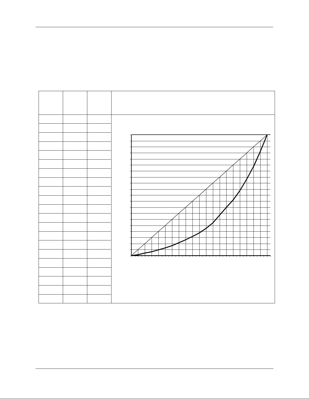
Equal Percentage Valve Characteristic
Table 9 contains values that approximate an equal percentage valve characteristic in the actuator. When the
EQUL custom characterization type is selected, the values in Table 9 are automatically loaded into the
actuator
configuration to produce the characteristic as presented in the graph. The Xn VAL is the input
value as a percentage of range and Yn VAL is the characterized output (actuator shaft position) as a
percentage of range.
Table 9 Equal Percentage Valve Characteristic Table
4. Set Up and Calibration Procedures - Input Set Up Group
Order
Xn VAL
% of
Range
Yn Val
% of
Range
0 0 0
1 5 0.8
2 10 2.1
3 15 3.2
4 20 4.9
5 25 6.5
6 30 8.4
7 35 10.7
8 40 13.2
9 45 15.7
10 50 18.7
11 55 22.6
12 60 27.2
13 65 33.4
14 70 40
15 75 46
16 80 53.8
17 85 63.2
Equal Percentage Valve Characterization
100
95
90
85
80
t
75
u
p
t
70
u
O
65
d
e
60
z
i
r
55
e
t
c
50
a
r
a
45
h
C
40
L
35
A
V
30
n
Y
25
20
15
10
5
0
10 20 30 40 50 60 70 80 90 100
Xn VAL - Actua l Input
18 90 73.7
19 95 86.2
20 100 100
Revision 5 10260S HercuLine® Actuator Installation, Operation and Maintenance Manual 37
7/07
Page 48
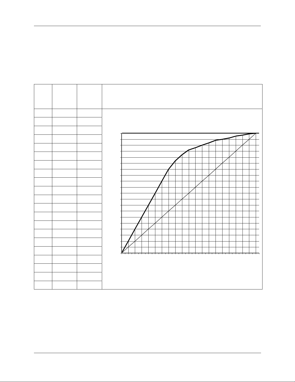
4. Set Up and Calibration Procedures - Input Set Up Group
Quick Opening Valve Characteristic
Table 10 contains values that approximate the characteristic of a quick opening control valve. When the
QUIK custom characterization type is selected, the values in Table 10 are automatically loaded into the
actuator
configuration to produce the characteristic as presented in the graph. The Xn VAL is the input
value as a percentage of range and Yn VAL is the characterized output (actuator shaft position) as a
percentage of range.
Table 10 Quick Opening Valve Characteristic Table
Xn VAL
Yn Val
Order
% of
Range
0 0 0
1 5 10
2 10 20
3 15 30
4 20 40
5 25 50
6 30 60
7 35 70
8 40 77
9 45 82
10 50 86
11 55 88
12 60 90
13 65 92
14 70 94
15 75 95
16 80 96
17 85 97.5
18 90 98.5
% of
Range
Quick Opening Valve Characteristic
100
95
90
85
80
t
75
u
p
t
70
u
O
65
d
e
60
z
i
r
55
e
t
c
50
a
r
a
45
h
C
40
L
35
A
V
30
n
Y
25
20
15
10
5
0
10 20 30 40 50 60 70 80 90 100
Xn VAL - Actual Input
19 95 99.5
20 100 100
38 10260S HercuLine® Actuator Installation, Operation and Maintenance Manual Revision 5
7/07
Page 49

Relays Set Up Group
ATTENTION
The Relay set up group parameters are accessible only if relay PWAs are installed in the
actuator. 10260S series actuators can be equipped with up to two relay PWAs –for a total of
four SPDT relays. Using the Relay set up groups you can program the installed relays to
operate in response to various operating conditions.
Table 11lists the parameters and selections
4. Set Up and Calibration Procedures - Relays Set Up Group
available when the SET RELAYn group is selected.
Table 11 Relay Set Up Group Parameters
Lower Display
Prompt
RTYPny
n = 1, 2, 3, or 4
y = 1 or 2
RnyE 9 †
Upper Display
Selections or
Range of Setting
NONE
[default]
or
InPR
PosR
DEV
ULim
LLim
T Hi
T Lo
STRT
STAL
MAN
PWRF
FsFA
PosF
DiGI
TDEG
X1
or
X10k
Parameter Definition
RELAY TYPE—Selects the relay number and the relay
activation type. See
Inpu
t Range—Upper / lower limits of input signal exceeded
Position Range—Upper / lower limits of motor position
exceeded
Deviation—Deviation from input exceeded
Upper Limit Travel—Same as PosR for upper limit
Lower Limit Travel—Same as PosR for lower limit
Temperature High—High temperature limit exceeded
Temperature Low—Low temperature limit exceeded
Starts—Motor starts limit exceeded
† Allows setting of multiplier value.
Stalled—Motor position does not follow input
Manual—Actuator is set to manual mode
Power Up Test Failure—Failure of any power up diagnostic
Failsafe Alarm—Failsafe condition detected
Position Sensor Signal Failure—NCS output out of valid
range
Digital Input—Digital input closure
Total Degrees— total degrees traveled.
MULTIPLIER—(Relay Type STRTS only) Selects the
multiplier for the number limit of motor starts before the relay
is activated. Multiplier specifies the value on display as
times one (X1) or times ten thousand (X10k).
Table 12 Relay Type Descriptions.
RnyVALn = 1,
2, 3, or 4
y = 1 or 2
Rny HLn = 1, 2,
3, or 4
y = 1 or 2
RLYnHY
n = 1, 2, 3, or 4
n is the relay number, y is the relay contact.
0.0 to 100.0
HILO RELAY HIGH/LOW—Sets relay trip point to high or low limit.
0.0 to 100.0
(in percent)
RELAY VALUE—Sets numerical value of limit where relay
trips (energizes). Units are determined by the relay type
selection. See
RELAY HYSTERESIS—0.0 to 100.0% of span or full output.
NOTE: Relay Hysteresis parameter is accessible only if
appropriate relay type is selected.
Table 12 Relay Type Descriptions for units.
Revision 5 10260S HercuLine® Actuator Installation, Operation and Maintenance Manual 39
7/07
Page 50
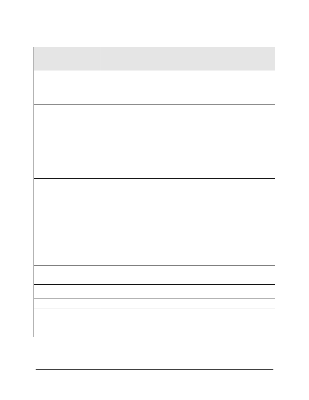
4. Set Up and Calibration Procedures - Relays Set Up Group
Table 12 Relay Type Descriptions
When this Relay Type is
selected…
(RTYP)
Input Range
Position Range
Deviation
Upper Limit Travel
Lower Limit Travel
Temperature High
The Relay can be set up to indicate …
The upper / lower limits of the input signal have been exceeded.
Relay value parameter defines range limits and units are in percent of full span.
Upper / lower limits of motor position have been exceeded.
Relay value parameter defines range limits and units are in either percent of
span or degrees of rotation. See “Relay Examples “for setting range limits.
Motor position has exceeded deviation limit from input. (Deviation is defined as:
setpoint – motor position = Deviation)
Relay value parameter defines limits and units are in percent of span.
See “Relay Examples” for setting deviation limit.
The motor position has exceeded the upper limit of travel. (Same as Position
Range.)
Relay value parameter defines limits and units are in degrees of rotation or
percent of span. See “Relay Examples” for setting upper limit with hysteresis.
The motor position has exceeded the lower limit of travel. (Same as Position
Range.)
Relay value parameter defines limits and units are in degrees of rotation or
percent of span.
The high temperature limit of the actuator has been exceeded. Range is -30 to
+75 °C. Relay value parameter defines temperature limits and units are in either
degrees C or degrees F.
Temperature Low
Starts
Stall
Manual Mode
Power Up Test Failure
Failsafe
Position Sensor Failure
Digital Input
Total Degrees
(Temperature units are defined in the UNITS setting of the DISPLA set up
group.)
The low temperature limit of the actuator has been exceeded. Range is -30 to
+75 °C. Relay value parameter defines temperature limits and units are in either
degrees C or degrees F.
(Temperature units are defined in the UNITS setting of the DISPLA set up
group.)
The accumulated motor starts have exceeded the limit. Relay value parameter
defines the limit. See “Relay Examples” for setting motor starts limit. Range is
from 10 to 99,990,000.
The motor is in a stall condition.
The actuator in in manual mode.
A failure of any one of the power up test diagnostics. See READ STATUS set up
group.
The actuator is in failsafe. (input signal loss or input signal out of valid range)
The sensor output is out of range or has failed.
The digital input closure.
The total degrees traveled. Range is from 10 to 99,990,000.
40 10260S HercuLine® Actuator Installation, Operation and Maintenance Manual Revision 5
7/07
Page 51
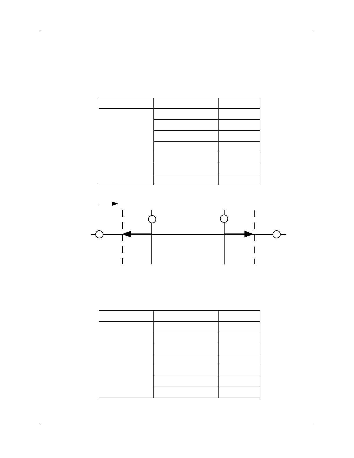
Relay Examples
Relay Type - Position Range
Selecting PosR relay type, you can cause the relay to energize when the actuator motor travels below 20%
of range and above 80% of range. Note in the example below that Relay 1 is set up to provide two trip
points. The first trip point (R11VAL) causes the relay to energize when the motor travels above 80%, the
second trip point (R12VAL) is set so the relay energizes when the motor travels below 20%.
Set Up Group Parameter Value
SET RELAY1 RTYP11 PosR
R11VAL 80.0
R11HL HI
RTYP12 PosR
R12VAL 20.0
R12HL LO
RLY1HY 0.0
The figure below shows the resulting action.
4. Set Up and Calibration Procedures - Relays Set Up Group
Motor
Position
18
Relay Type - Deviation
Setting up a relay to alarm (energize) when the motor position deviates 10% (+ or -) from the actuator
setpoint can be set up as follows.
100%
18
17
Closed
20%
80%
17
Open
Closed
RELAY 1
Normally Open
0%
Set Up Group Parameter Value
SET RELAY1 RTYP11 DEV
R11VAL 10.00
R11HL HI
RTYP12 DEV
R12VAL -10.00
R12HL LO
RLY1HY 0.0
The resulting action is shown below.
Revision 5 10260S HercuLine® Actuator Installation, Operation and Maintenance Manual 41
7/07
Page 52
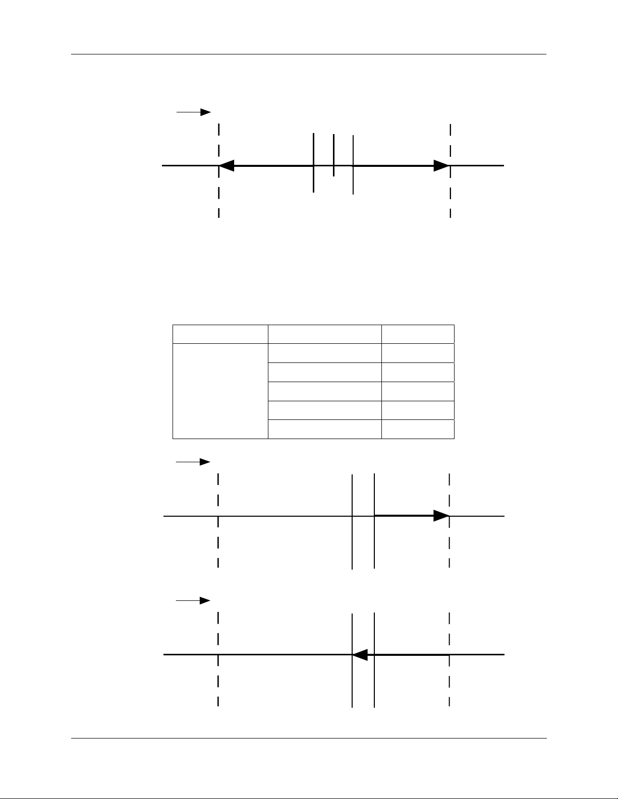
4. Set Up and Calibration Procedures - Relays Set Up Group
Relay Type – Deviation, continued
Motor
Position
0%
-10%
Input
50%
100%
+10%
Closed
Relay Type – Upper Limit Travel with Hysteresis
Selecting relay type ULim will cause the relay to energize when the motor position exceeds the upper limit
trip point, and can be set up as follows. Note that relay hysteresis parameter (RLY1HY) value is set to 10,
which is 10% of range. This means that when the relay is energized, due to the motor position exceeding
the upper limit value, the relay will not de-energize until the motor moves to 10% below the trip point.
Set Up Group Parameter Value
SET RELAY2 RTYP21 ULim
R21VAL 70.0
R21HL HI
RTYP22 NONE
RLY2HY 10.0
Motor
Position
0%
Open
RELAY n
Normal l y Ope n
60%
70%
Closed
100%
Open
Closed
RELAY n
Normally Ope n
Motor
0%
60%
70%
100%
Position
Open
Closed
RELAY n
Normally Ope n
42 10260S HercuLine® Actuator Installation, Operation and Maintenance Manual Revision 5
7/07
Page 53
Relay Type – Motor Starts
Selecting relay type STRT will cause the relay to trip when the number of motor starts exceeds the selected
limit. The motor starts value is stored as one of the maintenance group statistics. This example sets the
motor starts limit at 200,000 for Relay 1.
Set Up Group Parameter Value
SET RELAY1 RTYP11 STRT
4. Set Up and Calibration Procedures - Current Out Set Up Group
R11VAL 20
R11HL HI
RTYP12 NONE
The resulting action is that Relay 1 will trip when the number of accumulated motor starts in the
maintenance group exceeds 200,000.
Current Out Set Up Group
Table 13 lists the parameters and selections available for the SET CUROUT group.
ATTENTION
If you change the output signal range of the actuator, you must perform an output calibration.
See Calibrating Output, page 62.
When selecting the output range of the actuator, the 4 – 20 mA selection is factory calibrated, therefore no
calibration is necessary. If you change the CUROUT selection, you must perform an output calibration so
that the values at the actuator output terminals agree with the CUROUT selection.
Additionally, if you change the CUROUT selection back to 4 – 20 mA from another selection, you must
either perform an output calibration or perform a LD CAL function to the output (COUT) to restore the
factory calibration values to the 4 – to 20 mA selection. The LD CAL function is in the INPUT set up
group.
R11 E 9
X10K
Table 13 Current Out Set Up Group Parameters
Lower Display
Prompt
CUROUT
Note: If output
type from model
selection guide
is:
0/4-20mA, 0/1-
5Vdc
Revision 5 10260S HercuLine® Actuator Installation, Operation and Maintenance Manual 43
7/07
Upper Display
Selections
4 – 20
0 – 20
1 – 5V
0 – 5V
Parameter Definition
OUTPUT SIGNAL RANGE—Selects the signal output
range.
4 to 20 mA
0 to 20 mA
1 to 5 Volts
0 to 5 Volts
Page 54

4. Set Up and Calibration Procedures - Current Out Set Up Group
Lower Display
Prompt
CUROUT
Note: If output
type from model
selection guide
is:
Slidewire
Emulation
CUROUT
Note: If output
type from model
selection guide
is:
None
Upper Display
Selections
SW E Slidewire Emulation
NONE No current output configured.
Parameter Definition
44 10260S HercuLine® Actuator Installation, Operation and Maintenance Manual Revision 5
7/07
Page 55

4. Set Up and Calibration Procedures - Communications Set Up Group
Communications Set Up Group
Table 14 lists the parameters and selections available for the SET COMM group.
Table 14 Communications Set Up Group Parameters
Lower Display
Prompt
COMM
ADDRES
BAUD
XmtDLY
Upper Display
Selections or
Range of Setting
DIS
MODB
HART
1 to 99
2400
4800
9600
19.2k
NONE
10ms
20ms
30ms
40ms
50ms
Parameter Definition
COMMUNICATONS PARAMETERS—Disables or enables
parameter displays for Modbus communciations set up.
Disabled—Locks out access to communications displays
and parameters.
Modbus—Allows access to the communication displays and
settings for the parameters listed below.
HART - Selects HART as the Communications Protocol.
DEVICE ADDRESS—Selects device address when used in
a Modbus communications loop. Select an address that is
unique to other devices on the communications link.
BAUD RATE—Selects the speed of data transfer. All
equipment on the link must be set to match the host setting.
RESPONSE DELAY—Selects the time delay (in
milliseconds) before a response to a query is transmitted.
DBLBYT
FP B
FPBB
FP L
FPLB
FLOATING POINT DATA FORMAT—Selects the format for
transferring floating point data.
Byte Order
Floating Point Big Endian format— 0 1 2 3
Floating Point Big Endian format
with byte-swapped— 1 0 3 2
Floating Point Little Endian format— 3 2 1 0
Floating Point Little Endian format
with byte-swapped— 2 3 0 1
Revision 5 10260S HercuLine® Actuator Installation, Operation and Maintenance Manual 45
7/07
Page 56

4. Set Up and Calibration Procedures - Digital Input Set Up Group
Digital Input Set Up Group
Table 15 lists the parameters and selections availible for the SET DIGINP group.
Table 15 Digital Input Set Up Group Parameters
Lower Display
Prompt
DIGINP
EndPos *
Upper Display
Selections or
Range of Setting
(in percent)
Display Set Up Group
Table 16 lists the parameters and selections availible for the SET DISPLA group.
Parameter Definition
NONE
UP
DOWN
USER
0 – 100.
Digital Input State—Selects the position of the actuator in
response to a digital input signal (contact closure).
None—No action by the actuator.
Up—Actuator motor moves to full scale value.
Down—Actuator motor moves to zero value.
User selected value—Actuator motor moves to a customer-
selected value.
* Allows setting of End Position Value.
END POSITION VALUE—(DIGINP USER only) Selects the
motor position you want the actuator to go to when digital
input signal present (contact closure).
Table 16 Display Set Up Group Parameters
Lower Display
Prompt
DECMAL
EUNITS
46 10260S HercuLine® Actuator Installation, Operation and Maintenance Manual Revision 5
7/07
Upper Display
Selections or
Range of Setting
8888
[default]
or
888.8
PCNT
DEG
Parameter Definition
DECIMAL POINT LOCATION—This selection determines
where the decimal point appears in the display.
None
One Place
Note: Be sure the selection agrees with the value to be
displayed. If display value requires 4 whole digits, the
decimal will not show.
UNITS DISPLAY—Selects the units of the position display.
Percent—Shows actuator position as a percentage of span.
(0 to 100%)
Degrees—Shows the actuator position in degrees of
rotation. (0 to 90°). Note: Not accessible when characterizer
= CUST.
Continued on next page
⇒
Page 57

4. Set Up and Calibration Procedures - Lock Set Up Group
Lower Display
Prompt
UNITS
Lock Set Up Group
Table 17 lists the parameters and selections available for the SET LOCK group.
Lower Display
Prompt
LOCKID
Upper Display
Selections or
Range of Setting
SI
ENGL
Table 17 Lock Set Up Group Parameters
Upper Display
Selections or
Range of Setting
Nnnn
n = 1 to 9
(Up a limit of 4095)
Parameter Definition
DISPLAY UNITS—Selects standard for unit values for the
local display.
SI—Display will show unit values in international (metric)
units. (Temperature in degrees C, Date format: ddmmyy)
English—Display will show unit values in U.S. units.
(Temperature in degrees F, Date format: mmddyy)
Parameter Definition
PASSWORD LOCK—4-digit password can be selected to
provide security access to calibration information, set up
parameters and supervisory functions. Password can be a
number from 0 to 4095.
LOCK
MAENAB DIS
NONE
[default]
CAL
CONF
FULL
[default]
ENAB
A password is required in order to change the lock
parameter.
See “Set/Change Password” below.
LOCK OUT FEATURE—Selects lockout security for
calibration and supervisory functions, and set up groups.
None—No lockout of any calibration or set up groups. You
select and change set up group values, and perform field
calibration.
Calibration—Lockout for calibration groups SET CALIN,
SET CALMTR, SET CALOUT and CAL NCSOUT only. You
can select and change set up group values.
Configuration—Lockout for calibration groups and set up
group configuration. You can only scroll through and view
set up group values.
Full—Lockout for calibration and all set up group values.
Only SET LOCK and READ STATUS groups are accessible.
AUTO / MANUAL MODE LOCKOUT -DIS—disables the mode key on the keypad.
ENAB—enables the mode key on the keypad.
Revision 5 10260S HercuLine® Actuator Installation, Operation and Maintenance Manual 47
7/07
Page 58
4. Set Up and Calibration Procedures - Lock Set Up Group
Set/Change Password
A password is required to enable and disable lockout features of the actuator. Lock out of calibration
information and other supervisory functions are controlled using the password. The password can be any
number from 0 to 4095. The password is set and/or changed by using the keys on the kepad and the local
display. Follow the steps below to change the password.
NOTE: The LOCK parameter must be set to NONE in order to change the password.
Step Action
1 Press SET UP key until the display reads SET LOCK.
2 Press the FUNCTION key until the lower display reads LOCKID.
3
The upper display will show 0 (zero). Use the or keys to increment the number to the
correct password. The default password can also be used. See NOTE below.
4 Press the FUNCTION key so that the lower display reads LOCK.
5
Use the or keys so that display reads NONE and LOCK.
If the LOCK parameter is not set to NONE, a password must be entered to change the
parameter.
6 Press the FUNCTION key until the lower display reads LOCKID.
7
The upper display will show 0 (zero). Use the or keys to increment the number to the
new password. See NOTE below.
8 Press FUNCTION key to view next parameter, or press DISPLAY to exit set up mode.
Password is now set to new value.
NOTE:
When changing the value of the number, you can adjust a more significan t digit in the upper
display by holding in one key
The adjustment will move one digit to the left.
Press the key again and you will move one more digit to the left.
or and pressing the other or at the same time.
48 10260S HercuLine® Actuator Installation, Operation and Maintenance Manual Revision 5
7/07
Page 59

Read Status Set Up Group
Table 18 lists the parameters and selections available for the READ STATUS group.
Table 18 Read Status Set Up Group Parameters
4. Set Up and Calibration Procedures - Read Status Set Up Group
Lower Display
Prompt
FAILSF
RAMTST
SEETST
CFGTST
Upper Display
Selections or
Range of Setting
NO
YES
PASS
FAIL
PASS
FAIL
PASS
Parameter Definition
FAILSAFE—Read Only. Shows whether actuator in failsafe.
No—Actuator not in failsafe.
Yes—Actuator in failsafe, see Troubleshooting section
RAM TEST DIAGNOSTIC—Read Only. Shows status of
RAM test diagnostic.
Pass—Test passed, no errors
Fail—Test failed, see Troubleshooting section.
SERIAL EEPROM TEST DIAGNOSTIC—Read Only.
Shows status of serial electrically eraseable PROM test
diagnostic.
Pass—Test passed, no errors
Fail—Test failed, see Troubleshooting section.
CONFIGURATION TEST DIAGNOSTIC—Read Only.
Shows status of Configuration test diagnostic.
Pass—Test passed, no errors
CALTST
FAIL
PASS
FAIL
Fail—Test failed, see Troubleshooting section.
CALIBRATION TEST DIAGNOSTIC—Read Only. Shows
status of Calibration test diagnostic.
Pass—Test passed, no errors
Fail—Test failed, see Troubleshooting section.
Revision 5 10260S HercuLine® Actuator Installation, Operation and Maintenance Manual 49
7/07
Page 60

4. Set Up and Calibration Procedures - Drive Set Up Group
Drive Set Up Group
Table 19 lists the parameters and selections available for the SET DRVINF group.
Table 19 Drive Set Up Group Parameters
Lower Display
Prompt
VERSON
SPEED
(90° @ 60hz)
SPEED
(90° @ 50hz)
POWER
Upper Display
Selections or
Range of Setting
Nnnn FIRMWARE VERSION—Read Only. Displays the firmware
version currently in use by the actuator’s CPU.
10s
20s
40s
60s
20s
40s
60s
40s
60s
12s
24s
48s
72s
24s
48s
72s
48s
72s
STROKE SPEED—Read Only. The speed is the number of
seconds it takes for the actuator shaft to move its full range
of travel.
STROKE SPEED—Read Only. The speed is the number of
seconds it takes for the actuator shaft to move its full range
of travel.
POWER INPUT VOLTAGE AND FREQUENCY—Read
Only. Selects the power input voltage and line frequency of
the actuator.
Parameter Definition
1206
1205
2206
2205
TAG
ROTATE
TORQUE
50 10260S HercuLine® Actuator Installation, Operation and Maintenance Manual Revision 5
7/07
Nnnnnn TAG NAME—Selects the tag name or identifier of the
90
10 lb-ft / 15 N-M
20 lb-ft / 27 N-M
40 lb-ft / 55 N-M
60 lb-ft / 80 N-M
40 lb-ft / 55 N-M
80 lb-ft / 110 N-M
150 lb-ft / 200 N-M
200 lb-ft / 270 N-M
300 lb-ft / 400 N-M
1206—120Volts, 60Hz
1205—120Volts, 50Hz
2206—220Volts, 60Hz
2205—220Volts, 50Hz
actuator. Up to 6 alphanumeric characters. See “Set Tag
Name” on next page.
ROTATION— Indicates the factory calibrated degrees of
rotation.
90— Factory calibrated for 90 degrees of rotation.
Motor Torque value
Page 61

4. Set Up and Calibration Procedures - Drive Set Up Group
Lower Display
Prompt
MFGDAT
LREP
LCAL
REPTYP
Upper Display
Selections or
Range of Setting
mmddyy *
or
ddmmyy
mmddyy *
or
ddmmyy
mmddyy *
or
ddmmyy
NONE
01
02
03
04
05
06
07
08
09
10
11
12
13
Parameter Definition
MANUFACTURING DATE—Read Only. Displays datecode
of manufacture for actuator.
DATE OF LAST REPAIR—Factory set only. Displays date
of last repair.
DATE OF LAST FACTORY CALIBRATION—Factory set
only. Displays date of last factory calibration
REPAIR TYPE—Factory set only. Displays a repair code to
identify the type of repair service previously performed.
None
Future
Non-contact Sensor
Main CPU PWA repair
Motor service
Power Distribution PWA service
Switch repair
Relay service
Gear service
Service to repair water damage
Service to repair damage caused by heat
Service to repair due to over-voltage damage
Actuator reconfigured
Warranty Repair
* NOTE: Date format is set by the UNITS parameter. See SET DISPLA set up group.
Revision 5 10260S HercuLine® Actuator Installation, Operation and Maintenance Manual 51
7/07
Page 62

4. Set Up and Calibration Procedures - Drive Set Up Group
Set Tag Name
The actuator tag name can be an alphanumeric name up to six characters. The tag name is set by using the
keys on the keypad and the local display. Follow the steps below to set the tag name.
Step Action
1 Press SET UP key until the display reads SET DRVINF.
2 Press the FUNCTION key until the upper display reads TAG.
3
The lower display contains six digits. A decimal point will be flashing at the leftmost digit for
approximately three seconds. Then the decimal point shifts to the right and flashes for three
seconds before shifting again to the right. This pattern repeats continuously.
4
Set the digit to the left of the flashing decimal point. Use the or keys to scroll through
the character set of 0 through 9 and the letters A through Z. Scroll through until the desired
character is displayed.
5
Wait for the decimal point to shift to the right and then scroll through using the or keys
until the next character is displayed.
6 Repeat for each character of the tag until the complete tag name is displayed.
7 Press the FUNCTION key to go to the next parameter, or press DISPLAY to exit set up mode.
52 10260S HercuLine® Actuator Installation, Operation and Maintenance Manual Revision 5
7/07
Page 63

Maintenance Set Up Group
The Maintenance set up group consists of information about actuator operation accumulated through time.
This information (or maintenance statistics) can be used to evaluate actuator operation and determine
predicted or scheduled maintenance periods. Table 20 lists the parameters and selections
SET MAINTENANCE group.
Please note that maintenance statistics are written to the EEPROM every 8 hours. Therefore the statistics
are saved in the event of a power interruption.
Table 20 Maintenance Set Up Group Parameters
4. Set Up and Calibration Procedures - Maintenance Set Up Group
available for the
Lower Display
Prompt
TEMP nnnn F *
TEMPHI
TEMPLO nnnn F *
hh:mm:ss †
STARTS
RLnCNT
n = 1, 2, 3 or 4
REGNn
nx = 0 to 9
Upper Display
Selections or
Range of Setting
nnnn F *
ACST †
Parameter Definition
ACTUATO R TEMPERATURE—Read Only. Displays the
current internal temperature of the actuator.
HIGH TEMPERATURE LIMIT—Displays the high
nnnn ACCUMULATED MOTOR STARTS—Displays the
nnnn RELAY CYCLE COUNTS—Displays the accumulated cycle
nnnn ACCUMULATED MOTOR STARTS—Displays the
temperature limit of the internal actuator temperature since it
was last reset.
LOW TEMPERATURE LIMIT—Displays the low
temperature limit of the internal actuator temperature since it
was last reset.
ACCUMULATED STALL TIME—Displays the accumulated
stall time of the actuator motor since it was last reset.
accumulated motor starts since it was last reset.
counts of a relay since it was last reset. One relay cycle is
when a relay is energized and deenergized.
accumulated motor starts in the 1st 10% of motor span since
it was last reset. See “Regions of Motor Travel” in Section 5
TOTDEG
DATSAV
PASSWRD
Revision 5 10260S HercuLine® Actuator Installation, Operation and Maintenance Manual 53
7/07
nnnn TOTAL DEGREES OF MOTOR TRAVEL—Displays the
total number of degrees of motor travel since it was last
reset.
DIS
ENAB
nnnn PASSWORD—4-digit password is required to enable
MAINTENANCE DATA FORCED SAVE— Allows yo u to
manually force a save of the current maintenance data
values.
DISABLE— Forced data save is disabled.
ENABLE— Forced data save is enabled.
maintenance reset function.
NOTE: Password is set (or changed) from the Lock set up
group.
Page 64

4. Set Up and Calibration Procedures -
Lower Display
Prompt
Upper Display
Selections or
Parameter Definition
Range of Setting
MANRST
LD CAL
NONE
STAL
STRT
REGNn
n = 0 to 9
TEMP
TDEG
RELn
n = 1, 2, 3 or 4
ALL
SYST
NONE
[default]
INP
MTR
COUT
ALL
POS
MAINTENANCE STATISTIC RESET—Allows reset of the
following maintenance statistics:
None—No reset of maintenance statisitics
Stall—Resets accumulated stall time to zero.
Motor Starts—Resets accumulated motor start counts to
zero.
Motor Starts in the Region—Resets to zero the
accumulated motor starts for n
th
10% of motor span.
Temperature Statistics—Resets the high / low temperature
limit statistics to zero.
Total Degrees—Resets the total degrees of motor travel to
zero.
Relay Counts—Resets accumulated relay cycle counts to
zero for the relay option number displayed.
All—Resets all maintenance statistics to zero.
System Restart--Enables the system restart function
RESTORE CALIBRATION TYPE—Allows you to restore a
calbration value to its factory calibration.
Input—Restores input calibration to the factory calibration.
Motor—Restores motor calibration to the factory calibration.
Output—Restores actuator output calibration to the factory
calibration. For 4-20 mA output only; all other CUROUT
selections require output calibration.
All—Restores input, motor and output calibration to the
factory calibrations.
Position Sensor—Restores position sensor calibration to
the factory calibration.
NOTE: Allows a position sensor field calibration to be stored
as a factory calibration. This is to be used after replacement
of the sensor in the field. See “Calibrate POS Output”.
LD CFG DIS
ENAB
RESTORE DEFAULT FACTORY CONFIGURATION---
Allows you to restore the factory default configuration values.
DIS --- Restore disabled.
ENAB --- Restore enabled.
RESTRT DIS
ENAB
SYSTEM RESTART --- Allows you to force the system to go
thru a restart.
DIS --- Restart disabled.
ENAB --- Restart enabled.
Note: The MANRST function must be set to SYST.
* Temperature units are displayed in degrees C or F, and are set by the UNITS parameter. See SET
DISPLA set up group.
† Note that the upper display contains the parameter name and the lower display contains the value.
This is to allow for the display of hours: minutes: seconds.
54 10260S HercuLine® Actuator Installation, Operation and Maintenance Manual Revision 5
7/07
Page 65
CAL POSOUT Group
The CAL POSOUT group is used to verify that the position sensor is operating and adjusted properly. This
group allows the local display to indicate the output voltage of the position sensor PWA. This display is
used when verifying that the sensor is operating and that it is properly calibrated. Table 21 shows the
selections available for th
4. Set Up and Calibration Procedures - CAL POSOUT Group
e CAL POSOUT group.
Table 21 CAL POSOUT Group Parameters
Lower Display
Prompt
CALPOS n.nnn *
Upper Display
Selections or
Range of Setting
POSITION SENSOR OUTPUT—Read Only. Displays the
output voltage of the position sensor PWA
To access the display…
FUNCTION Upper Display = DIS
FUNCTION
Press Result
SETUP
until you see
or key
Upper Display = CAL
Lower Display = POSOUT
Lower Display = CALPOS
Upper Display = BEGN
Lower Display = CALPOS
Upper Display = n.nnn (Sensor output in volts)
Lower Display = POSOUT
Auto - Manual Drive Switch
The Auto - Manual switch is located on the side of the actuator case below the handwheel. The switch
allows manual mode control of the actuator motor for set up, calibration and troubleshooting. Figure 16
shows an illustration of the Auto
Manual Dri
ve switch setting overrides all input signals (analog signal and remote setpoint) and local
display mode settings.
- Manual switch and Table 22 describes the switch settings. The Auto -
Parameter Definition
Revision 5 10260S HercuLine® Actuator Installation, Operation and Maintenance Manual 55
7/07
Page 66

4. Set Up and Calibration Procedures - Auto - Manual Drive Switch
MANUAL
OFF
OFF
A
U
T
O
CWCCW
AUTO - MANUAL DRIVE
Figure 16 Auto - Manual Switch
Table 22 Auto - Manual Switch Functions
Switch Setting Motor Drive Control
AUTO
CCW
CW
OFF
Actuator moves according to signal input and set up configuration.
Actuator moves to the fully counterclockwise position.
Actuator moves to the fully clockwise position.
Actuator is idle.
56 10260S HercuLine® Actuator Installation, Operation and Maintenance Manual Revision 5
7/07
Page 67
Calibration
Calibration of the 10260S Series Actuator may consist of calibrating the position sensor, calibrating the
motor circuit that positions the actuator with 0/4-20mA input signal, or calibrating the slidewire emulation
output or the 0/4-20mA output signal.
Calibration is performed by connecting test equipment to the input terminals or output terminals and then
using the keypad and display to step through the calibration group functions.
ATTENTION
Input calibraton and output calibrations are performed at the factory and may not be
necessary. Normally, you may only need to perform Calibrate Motor.
Only qualified personnel should perform calibration.
Equipment Needed
The table below lists the equipment you will need to calibrate the 10260S input and output circuits.
4. Set Up and Calibration Procedures - Calibration
Procedure Equipment Needed
Input Calibration
Output Calibration
• A calibrated signal source which can provide current (0/4 mA
to 20 mA) or voltage (0 V to 10 V) with an accuracy of 0.02 %
or better.
• Two insulated copper leads for connecting the current source
to the actuator.
• A digital voltmeter with an accuracy of 0.01 % or better.
• A 250-ohm resistor 0.01 % tolerance.
Revision 5 10260S HercuLine® Actuator Installation, Operation and Maintenance Manual 57
7/07
Page 68
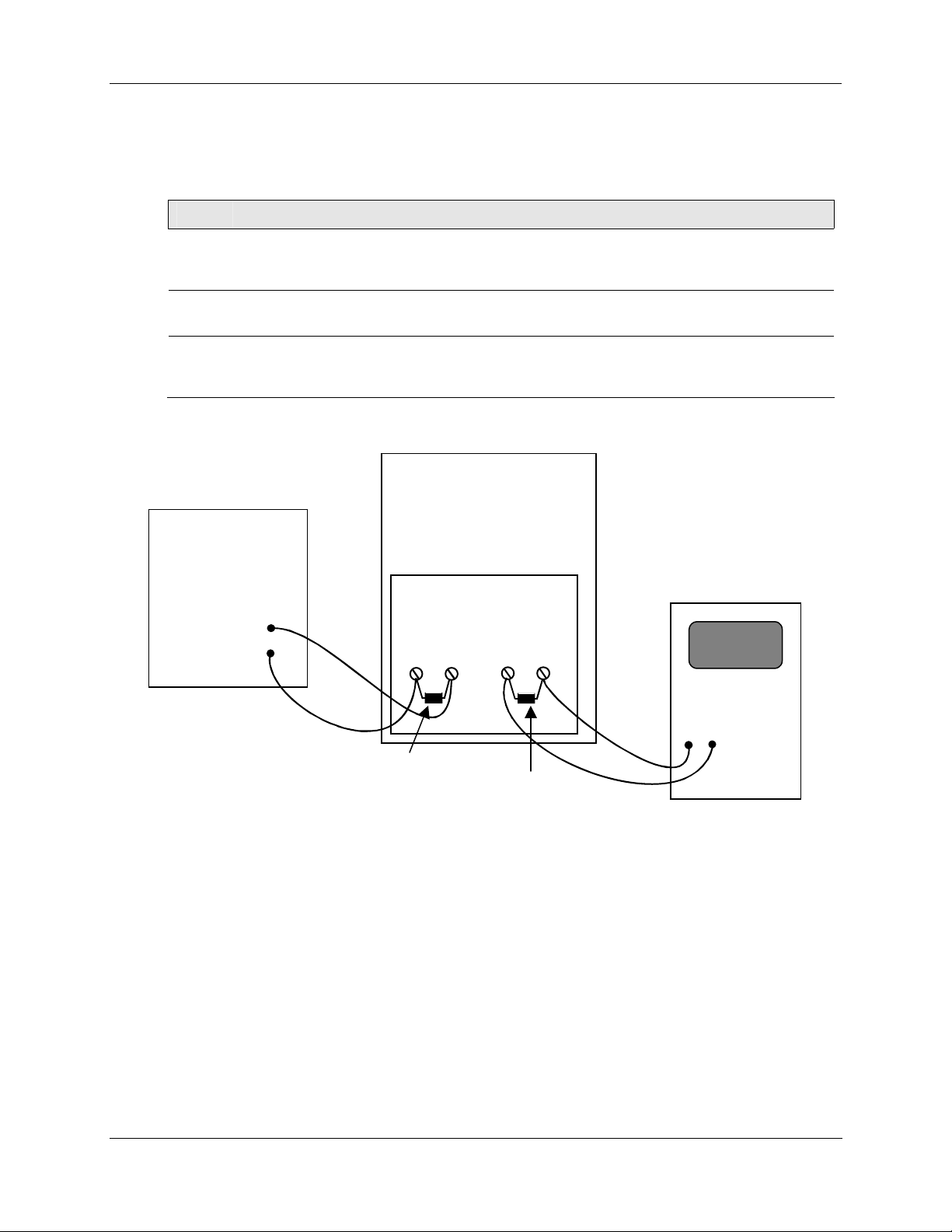
4. Set Up and Calibration Procedures - Calibration
Calibration Set up
Follow the steps below to set up the test equipment and actuator to verify calibration or perform calibration
procedures.
Step Action
1
Connect the copper leads from the signal source to the input terminals of the actuator as
shown in Figure 17 or Figure 18.
2
Place signal source output to low end of input signal and switch power on.
3
Skip this step for slidewire emulation. Connect a 250-ohm resistor across the Output terminals
of the actuator and connect the DVM leads to the terminals.
Actuator
Calibrated
Signal
Source
+
-
Input
28 29
-+
Output
30 31
-+
Digital
Voltmeter
+ -
250 ohm resistor
needed for current
signal source
Figure 17 Calibration Wiring Connections (except slidewire emulation)
250 ohm resistor
(supplied)
58 10260S HercuLine® Actuator Installation, Operation and Maintenance Manual Revision 5
7/07
Page 69
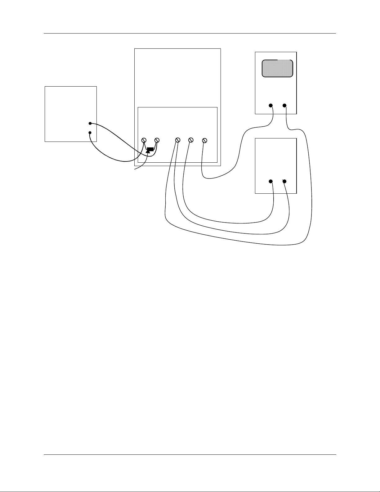
Calibrated
Signal
Source
4. Set Up and Calibration Procedures - Calibration
Actuator
Digital
Voltmeter
+ -
Terminal Block
+
-
Input
28 29
-+
Output
30 31 32
-+
FB
Power
Supply
1-18 VDC
250 ohm resistor
+ -
needed for current
signal source
Figure 18 Calibration Wiring Connections (slidewire emulation)
Revision 5 10260S HercuLine® Actuator Installation, Operation and Maintenance Manual 59
7/07
Page 70
4. Set Up and Calibration Procedures - Calibration
Calibrate Input
The 10260S actuator accepts a variety of signal inputs.
1. 0 mA to 20 mA, or 4 mA to 20 mA
2. 0 Volts to 5 Volts, 1 Volt to 5 Volts, or 0 Volts to 10 Volts
The input type is selected through the Input set up group using the local keypad.
Refer to Figure 17 for the wiring connections and follow the procedure in Table 23 to calibrate the input
cuit of the 10260 S actuator.
cir
ATTENTION
For an input calibration to be saved, you must complete the procedure. The calibration will not
be saved if you exit without completing the steps of the procedure.
To exit calibation mode, press DISPLAY or SETUP keys.
Table 23 Input Calibration Procedure
Step Operation Press Result
1
Enter Calibration
Mode
SETUP
until you see
Upper Display = CAL
Lower Display = INPUT
FUNCTION Upper Display = DIS
Lower Display = CAL IN
or key
Upper Display = BEGN
Lower Display = CAL IN
2 Calibrate Zero (0%) FUNCTION Upper Display = APLY
Lower Display = INZERO
• Adjust the signal source to an output value equal
to 0% range value.
• Wait 5 seconds, then go to step 3.
3
Calibrate Span
(100%)
FUNCTION Upper Display = APLY
Lower Display = INSPAN
• Adjust the signal source to an output value equal
to 100% range value.
• Wait 5 seconds, then go to step 4.
4 FUNCTION
Calibration for zero and span input values are now
saved. Input calibration is complete.
NOTE: . You may also exit calibration mode by
pressing the DISPLAY or SETUP keys.
60 10260S HercuLine® Actuator Installation, Operation and Maintenance Manual Revision 5
7/07
Page 71
4. Set Up and Calibration Procedures - Calibration
Calibrate Motor
Use the procedure in Table 24 to calibrate the actuator motor for 0 % and 100 % input signal
ATTENTION
For a motor calibration to be saved, you must complete the procedure. The calibration will not
be saved if you exit without completing the steps of the procedure.
Table 24 Motor Calibration Procedure
Step Operation Press Result
1
Enter Calibration
Mode
SETUP
until you see
Upper Display = CAL
Lower Display = MOTOR
FUNCTION Upper Display = DIS
Lower Display = CALMTR
or key
Upper Display = BEGN
Lower Display = CALMTR
2 Calibrate Zero (0%) FUNCTION Upper Display = APLY
Lower Display = MTR LO
• Use the Handwheeel or AUTO/MANUAL switch to manually
drive the actuator motor to its low position.
• Wait 5 seconds, then go to step 3.
3
Calibrate Span
(100%)
FUNCTION Upper Display = APLY
Lower Display = MTR HI
• Use the Handwheeel or AUTO/MANUAL switch to manually
drive the actuator motor to its high position.
• Wait 5 seconds, then go to step 4.
4 FUNCTION
Calibration for zero and span motor positions are now saved.
Motor calibration is complete.
NOTE: See Table 25. You may also exit calibration mode by
pressi
ng the DISPLAY or SETUP keys.
NOTE: If you are calibrating the motor to a short stroke range, the procedure is the same.
ATTENTION
When calibrating the motor to a short stroke range, you must reset the end-of-travel limit
switches. See Setting End-of-Travel Limit Switches.
Revision 5 10260S HercuLine® Actuator Installation, Operation and Maintenance Manual 61
7/07
Page 72
4. Set Up and Calibration Procedures - Calibration
Calibrate Output
10260S actuator can be one of three output types:
1. 0 mA to 20 mA, or 4 mA to 20 mA output
2. 0 Volts to 5 Volts, or 1 Volt to 5 Volts with 250 ohm range resistor
3. Slidewire emulation.
The output signal range is selected through the Current Out set up group using the keypad and local
display.
0/4-20 mAor 0/1-5 Volts Output
The 10260S Actuator comes already calibrated from the factory. If it becomes necessary to do a calibration
in the field, adjust the output using the procedure in Table 25. Refer to Figure 17 for a diagram to connect
a sign
al source to the actuator input and a DVM to measure actuator output signal.
This procedure provides the steps to calibrate the actuator for a 0/4 to 20mA output. If you are using
another output type, change the procedure accordingly. Please note that the actuator output is factory
calibrated for
only the 4 – 20 mA output selection. Any other output selection will require you to perform
an output calibration.
ATTENTION
For an output calibration to be saved, you must complete the procedure. The calibration will
not be saved if you exit without completing the steps of the procedure.
To exit calibation mode, press DISPLAY or SETUP keys.
Table 25 Output Calibration Procedure
Step Operation Press Result
1
Enter Calibration
Mode
SETUP
until you see
Upper Display = CAL
Lower Display = OUTPUT
FUNCTION Upper Display = DIS
Lower Display = CALOUT
or key
Upper Display = BEGN
Lower Display = CALOUT
2 Calibrate Zero (0%) FUNCTION Upper Display = xxx
Lower Display = ZERO
• Read meter connected to actuator output.
Procedure continued on next page ⇒
62 10260S HercuLine® Actuator Installation, Operation and Maintenance Manual Revision 5
7/07
Page 73
4. Set Up and Calibration Procedures - Calibration
Step Operation Press Result
2,
cont’d
3
4 FUNCTION
Calibrate Span
(100%)
or key
FUNCTION Upper Display = xxxx
or key
• Adjust actuator output to a value equal to 0% output as read
from the DVM.
NOTE: Typically for a 4 mA output, the display will show a value
of approximately 381. A lower limit value is imposed on the zero
output. If the value is 357 or lower, the actuator will not allow you
to calibrate the zero output. The value must be larger than 357
for a valid calibration.
Lower Display = SPAN
• Read meter connected to actuator output.
• Adjust actuator output to a value equal to 100% output as read
from the DVM.
• NOTE: Typically for a 20 mA output, the display will show a
value of approximately 1981.
Calibration for zero and span output values are now stored.
Output calibration is complete.
Slidewire Emulation
The 10260S Actuator comes already calibrated from the factory. If it becomes necessary to do a calibration
in the field, adjust the output using the procedure in Table 26. Refer to Figure 18 for a diagram to connect a
signal source to the actuat
or input and a DVM to measure actuator output signal.
ATTENTION
For a slidewire emulation output calibration to be saved, you must complete the procedure.
The calibration will not be saved if you exit without completing the steps of the procedure.
To exit calibration mode, press DISPLAY or SETUP keys.
Table 26 Slidewire Emulation Calibration Procedure
Step Operation Press Result
1
Enter Calibration
Mode
SETUP
until you see
Upper Display = CAL
Lower Display = OUTPUT
FUNCTION Upper Display = DIS
Lower Display = CALOUT
Revision 5 10260S HercuLine® Actuator Installation, Operation and Maintenance Manual 63
7/07
or key
Upper Display = BEGN
Lower Display = CALOUT
Page 74
4. Set Up and Calibration Procedures - Calibration
Step Operation Press Result
2 Calibrate Zero (0%) FUNCTION Upper Display = xxx
Lower Display = ZERO
xxx = arbitrary number assigned by software
3
Calibrate Span
(100%)
or key
FUNCTION Upper Display = xxxx
or key
Adjust actuator output voltage using down key until value on
DVM ceases to change, then press up key until value on DVM
moves up one digit
Lower Display = SPAN
xxx = arbitrary number assigned by software
Adjust actuator output voltage using up key until value on DVM
ceases to change, then press down key until value on DVM
moves down one digit
FUNCTION Calibration for zero and span output values are now stored.
Slidewire Emulation Output Calibration is complete. Read meter
connected to actuator output.
Calibrate Position Sensor
ATTENTION
The Position Sensor is factory calibrated to a full span, 90 degree rotation. Under
normal operation, the position sensor does not require calibration.
NOTE: Before you perform a calibration of the position sensor, it is recommended that you first verify the
voltage output from the sensor PWA. See “
Position Sensor Operation” in section 5 for the procedure.
Position sensor calibration may be necessary due to any of the following conditions:
• The sensor PWA output is incorrect,
• The sensor Printed Wiring Assembly (PWA) in the actuator has been replaced,
• The sensor spoiler adjustment has been disturbed.
When the position sensor PWA has been replaced (or serviced), you should perform a calibration of the
sensor circuit and then store it as the motor factory calibration. Please note that performing this procedure
will destroy any previously stored motor factory calibration values. Table 27 outlines the steps to perform
a
calibration to the NCS circuit.
WARNING
While the unit is powered, a potentially lethal shock hazard exists inside the case.
64 10260S HercuLine® Actuator Installation, Operation and Maintenance Manual Revision 5
7/07
Page 75

4. Set Up and Calibration Procedures - Calibration
Table 27 Non Contact Sensor Calibration Procedure
Step Action
1
Remove AC power to the actuator.
2
Remove the seven screws and the extended cover from the actuator case. See Figure 2.
Lay extended cover assembly on a flat surface.
3
Reapply AC power to the actuator.
4 Press SET UP key to access the INPUT set up group.
Press FUNCTION key until the lower display reads Direct.
Press the
NOTE: Actuator direction must be set to CCW for this procedure. Direction can be changed
after calibration is complete.
5
Drive the actuator to the 50% position (this refers to the position on the actuator scale for CCW
rotation). This should be done manually with the handwheel or with the AUTO - MANUAL
switch.
or keys to set Actuator Rotation direction to CCW.
6 Press SET UP key until the display reads CAL POSOUT.
Press the FUNCTION key until the dispaly reads DIS CALPOS.
Press the
Press FUNCTION key.
The upper display now shows the output of the non-contact sensor PWA in Volts.
7
Loosen the allen screw in the hub of the NCS spoiler just enough to be able to rotate the
spoiler. See Figure 19.
8
Adjust the NCS spoiler so that the voltage in the local display is 2.500 + or – 0.020 volts dc.
The allen screw should be almost in a vertical position. The bottom edge of the spoiler should
almost be horizontal in relation to the NCS PWA. See Figure 19.
or keys until the lower display reads BEGN CALPOS.
9
Tighten NCS spoiler set screw with an allen wrench, holding spoilers located on each side of
the NCS PWA in position.
IMPORTANT: Spoilers need to be held in position both rotationally and longitudina lly along
the drive shaft extension. An air gap must be maintained between the surface of the PWA and
each spoiler. (Any plastic or paper insulating material may be used to create this gap while
positioning the spoilers). Make sure that neither spoiler is touching the sensor PWA when the
adjustment is complete.
10
11
Revision 5 10260S HercuLine® Actuator Installation, Operation and Maintenance Manual 65
7/07
Press DISPLAY key to exit calibration mode.
Remove AC power to the actuator.
Page 76
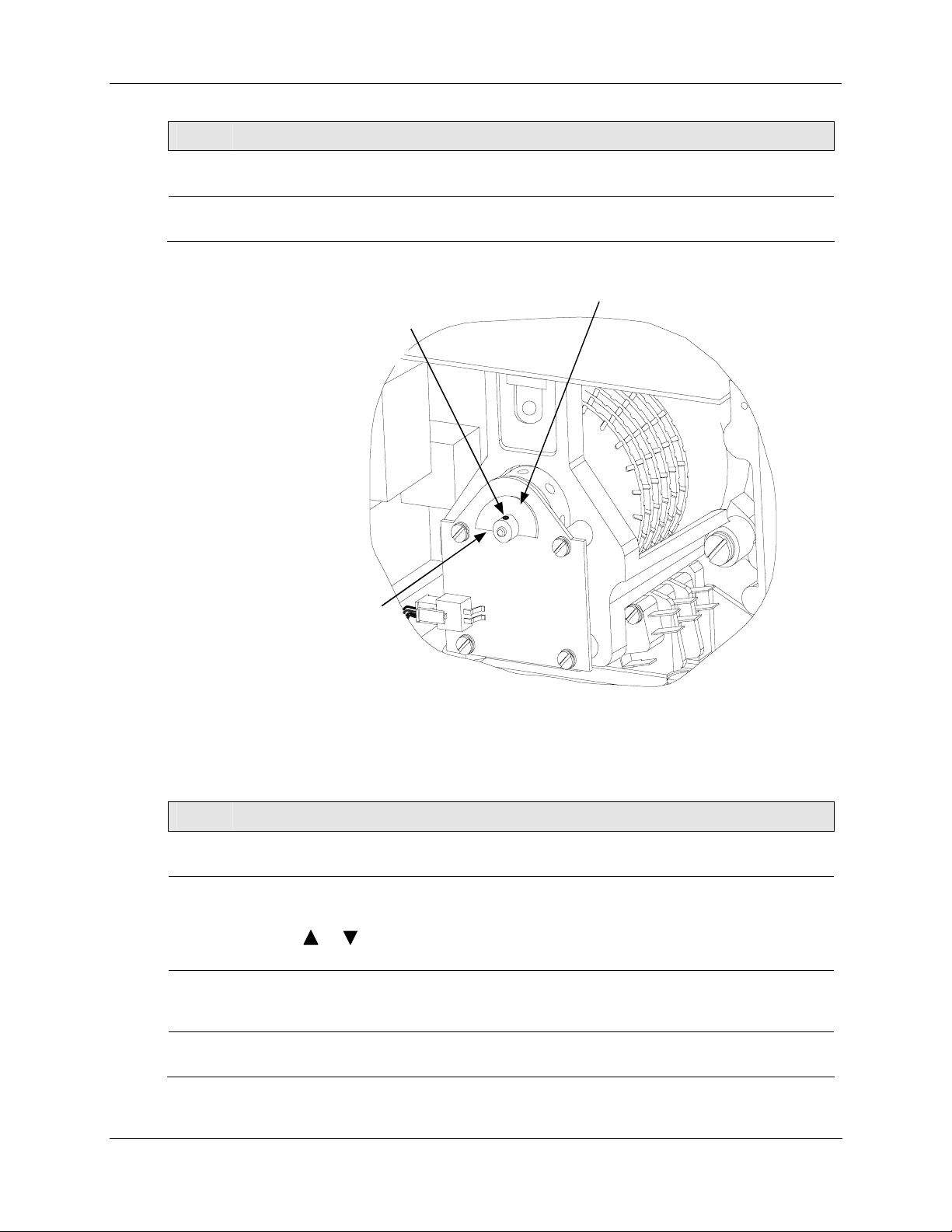
4. Set Up and Calibration Procedures - Calibration
Step Action
12
13
Install a new gasket and replace extended cover. Secure to actuator with screws.
Continue with calibration procedure in Table 28.
NCS Spoiler Set Screw
Allen Screw
0.05" Hex
Bottom of NCS spoiler
should be almost horizontal
when properly positioned
NCS PWA
NCS Spoiler
Figure 19 Location of NCS Assembly
Table 28 Load NCS Factory Calibration
Step Action
1
Reapply AC power to the actuator.
2
Press SET UP key to access the MAINT set up group. Press the FUNCTION key until the
display reads LD CAL.
Press the
3
Perform the Calibrate Motor procedure exactly as in Table 24. Motor calibration must be
performed for full span range.
4
When motor calibration is complete, the calibration is now stored as the factory calibration of
the actuator motor.
66 10260S HercuLine® Actuator Installation, Operation and Maintenance Manual Revision 5
7/07
or keys until the display reads POS.
Page 77

4. Set Up and Calibration Procedures - Setting End-of-Travel Limit Switches (actuators mfd. pre-1/1/03)
Setting End-of-Travel Limit Switches (actuators mfd. pre-1/1/03)
WARNING
While the unit is powered, a potentially lethal shock hazard exists inside the case.
ATTENTION
The first two cams (starting from the back) are for the 0 % and 100 % limit switches and should not need
any adjustments as they are factory set to stop the drive at 0 % and 100 %.
To adjust the limit switch cams (see Figure 20):
1. Remove the cover. (Non-contact sensor and terminal cover, see Figure 1.)
rn the locking nut, found behind the sensor, counter-clockwise using a 1/8” allen wrench or the
2. Tu
equivalent inserted into the radial holes in the locking nut until it is possible to turn the cams with your
fingers.
3. Using a slotted screwdriver on the slots at the edge of the cams, or your finger, rotate the cams until the
switches are set. (See Figure 21 .)
• Rotate the actuator shaft, using the manual handwheel or the auto/manual switch, to the 0 %
position (this is the 0 % for CCW operation using the left-hand scale or 100 % for CW operation
using the right hand scale). If the actuator is installed on a damper or valve, also make sure that
this position is synchronized with the travel of the final control element.
• Rotate the #1 limit switch operating cam to activate at this position. The switch roller arm should
go from being in an up, not depressed state, to a depressed state as the cam is rotated in the
direction of the shaft rotation going toward the limit position. This will cause the switch to go
from NC to NO and turn off the power to the motor when the switch activates. Switch activation
may be detected by the clicking sound or with a continuity tester connected to the terminals. Both
the NC and NO contact states are available to the customer at the terminals (see Figure 13 page
26).
• Rotate the actuator shaft, using the manual handwheel or the auto/manual switch, to the 100 %
position (this is 100 % for CCW operation using the left-hand scale or 0 % for CW operation
using the right hand scale). If the actuator is installed on a damper or valve, also make sure that
this position is synchronized with the travel of the final control element.
• Rotate the #2 limit switch operating cam to activate at this position. The switch roller arm should
go from being in an up, not depressed state, to a depressed state as the cam is rotated in the
direction of the shaft rotation going toward the limit position. This will cause the switch to go
from NC to NO and turn off the power to the motor when the switch activates. Both the NC and
NO contact states are available to the customer at the terminals (see Figure 13 page 26).
• If optional auxiliary switches were ordered, these switches may also be set at this time. (See page
70 for details of setting auxiliary switches.)
4. Once the cam
s are set in the correct positions, turn the locking nut clockwise until snug tight (it does
not have to be “hard” tight and does not have to completely flatten the spring washer).
5. Double check limit switch actuation by first manually driving the actuator to each end of travel and
hearing the switch click or by detecting it with a continuity tester. Secondly, drive the actuator to both
ends of travel (using the auto/manual switch or by providing minimum and full input signal) and make
sure the switches activate and turn off the motor.
Revision 5 10260S HercuLine® Actuator Installation, Operation and Maintenance Manual 67
7/07
Page 78

4. Set Up and Calibration Procedures - Setting End-of-Travel Limit Switches (actuators mfd. after 1/1/03)
ATTENTION
Make sure not to set the switch too close to the hard stop.
REFERENCE
An unactuated switch will have its normally closed (NC) contacts closed and its normally open (NO)
contacts open.
An actuated switch will have its NC contacts become open and its NO contacts become closed. Both NC
and NO contacts are available to the customer on the terminal board (see Figure 13 page 26).
An unactu
the cam.
ated switch has its roller arm in the up position when adjacent to the reduced diameter portion of
Setting End-of-Travel Limit Switches (actuators mfd. after 1/1/03)
WARNING
While the unit is powered, a potentially lethal shock hazard exists inside the case.
ATTENTION
The first two cams (starting from the back) are for the 0 % and 100 % limit switches and should not need
any adjustments as they are factory set to stop the drive at 0 % and 100 %.
To adjust the limit switch cams (see Figure 20):
emove the cover (terminal cover, see Figure 1).
1. R
2. Using a slotted screwdriver
switches are set (see Figure 20).
• Rotate the actuator shaft, using the manual handwheel or the auto/manual switch, to the 0 %
position (this is the 0 % for CCW operation using the left-hand scale or 100 % for CW operation
using the right hand scale). If the actuator is installed on a damper or valve, also make sure that
this position is synchronized with the travel of the final control element.
on the slots at the edge of the cams, or your finger, rotate the cams until the
• Rotate the #1 limit switch operating cam to activate at this position. The switch roller arm should
go from being in an up, not depressed state, to a depressed state as the cam is rotated in the
direction of the shaft rotation going toward the limit position. This will cause the switch to go
from NC to NO and turn off the power to the motor when the switch activates. Switch activation
may be detected by the clicking sound or with a continuity tester connected to the terminals. Both
the NC and NO contact states are available to the customer at the terminals (see Figure 13 page
26).
• Rotate the actuator shaft, using the manual handwheel or the auto/manual switch, to the 100 %
position (this is 100 % for CCW operation using the left-hand scale or 0 % for CW operation
using the right hand scale). If the actuator is installed on a damper or valve, also make sure that
this position is synchronized with the travel of the final control element.
68 10260S HercuLine® Actuator Installation, Operation and Maintenance Manual Revision 5
7/07
Page 79

4. Set Up and Calibration Procedures - Setting End-of-Travel Limit Switches (actuators mfd. after 1/1/03)
• Rotate the #2 limit switch operating cam to activate at this position. The switch roller arm should
go from being in an up, not depressed state, to a depressed state as the cam is rotated in the
direction of the shaft rotation going toward the limit position. This will cause the switch to go
from NC to NO and turn off the power to the motor when the switch activates. Both the NC and
NO contact states are available to the customer at the terminals (see Figure 13 page 26).
• If optional auxiliary switches were ordered, these switches may also be set at this time. (See page
73 for details of setting auxiliary switches.)
3. No
additional adjustments are required.
4. Double check limit switch actuation by first manually driving the actuator to each end of travel and
hearing the switch click or by detecting it with a continuity tester. Secondly, drive the actuator to both
ends of travel (using the auto/manual switch or by providing minimum and full input signal) and make
sure the switches activate and turn off the motor.
Revision 5 10260S HercuLine® Actuator Installation, Operation and Maintenance Manual 69
7/07
Page 80

4. Set Up and Calibration Procedures - Setting Auxiliary Switches (actuators mfd. pre-1/1/03)
Setting Auxiliary Switches (actuators mfd. pre-1/1/03)
WARNING
While the unit is powered, a potentially lethal shock hazard exists inside the case.
ATTENTION
The first two cams (starting from the back) are for the 0 % and 100 % end of travel limit switches
and should not need any adjustments as they are factory set to stop the actuator at 0 % and 100
%. See page 67 for setting end of travel limit switches (Switches #1 and #2)
If optional au
switches #3 and #4 and to 20 % and 80 % for switches #5 and #6. Additional switch settings
should be set so that switch #3 operates in synchronism with switch #1 (i.e., both activating when
the actuator is going in the same direction) and switch #4 to operates in synchronism with switch
#2, etc.
To adjust the next auxiliary switch cams (see Figure 22 ):
emove the cover. (Non-contact sensor and terminal cover, see Figure 1.)
1. R
2. Tu
equivalent inserted into the radial holes in the locking nut until it is possible to turn the cams with your
fingers.
3. Using a slotted screwdriver on the slots on edge of cams, or your fingers, rotate the cams until the
switches are set. (See Figure 20.)
• The auxiliary switches should be set so switches #3 and #5 operate in synchronism with switch #1
For Switches #3 and #5:
• Rotate the actuator shaft, using the manual handwheel or the auto/manual switch, to the desired
• Rotate the #3 switch operating cam to activate at this position. The switch roller arm should go
xiliary switches were ordered, these switches are factory set to 10 % and 90 % for
rn the locking nut, found behind the sensor, counter-clockwise using a 1/8” allen wrench or
(i.e., both activating when the drive is going in the same direction) and set switches #4 and #6 to
operate in synchronism with switch #2.
low scale position.
from being in an up, not depressed state, to a depressed state as the cam is rotated in the direction
of the shaft rotation going toward the limit position. This will cause the switch to go from NC to
NO when the switch activates. Switch activation may be detected by the clicking sound or with a
continuity tester connected to the terminals. Both the NC and NO contact states are available to
the customer at the terminals (see Figure 13 page 26).
• Repeat for Switch #5 if applicable.
For Switches #4 and #6:
• Rotate the actuator shaft, using the manual handwheel or the auto/manual switch, to the desired up
scale position.
• Rotate the #4 switch operating cam to activate at this position. The switch roller arm should go
from being in an up, not depressed state, to a depressed state as the cam is rotated in the direction
of the shaft rotation going toward the limit position. This will cause the switch to go from NC to
NO when the switch activates. Both the NC and NO contact states are available to the customer at
the terminals (see Figure 13 page 26).
• Repeat for Switch #6 if applicable.
70 10260S HercuLine® Actuator Installation, Operation and Maintenance Manual Revision 5
7/07
Page 81
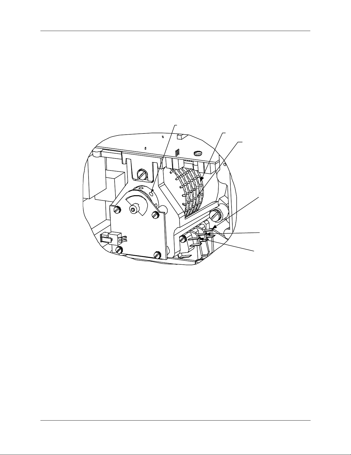
4. Set Up and Calibration Procedures - Setting Auxiliary Switches (actuators mfd. pre-1/1/03)
4. Once the cams are set in the correct positions, turn the locking nut clockwise until snug tight (it does
not have to be “hard” tight and does not have to completely flatten the spring washer).
5. Double check limit switch actuation by first manually driving the actuator to each end of travel and
hearing the switch click or by detecting it with a continuity tester. Secondly, drive the actuator to both
ends of travel (using the auto/manual switch or by providing minimum and full input signal) and make
sure the switches activate.
LOCKING
NUT
CAM 1 (REF)
CAM
SLOTS
SWIT CH 1
SWIT CH 3
SWIT CH 5
NOTE: Switches 2, 4 and 6
are located on le ft si de .
Figure 20 Location of Auxiliary Switches
Revision 5 10260S HercuLine® Actuator Installation, Operation and Maintenance Manual 71
7/07
Page 82
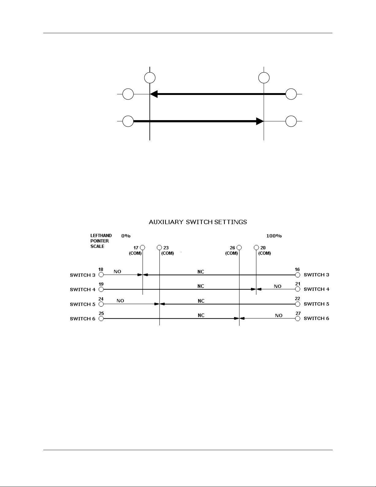
4. Set Up and Calibration Procedures - Setting Auxiliary Switches (actuators mfd. pre-1/1/03)
End of travel limit switch settings
100%
Left hand
Pointer scale
SW#1
14
0%
8 (SW1 COM) 9 (SW2 COM)
NC
7
SW#2
NC
155
Clockwise and counterclockwise rotation is the direction of the output shaft when facing the end
of the shaft. As shown, clockwise rotation of the output shaft activates SW#1 (at 0% on left hand
pointer scale) and CCW rotation activates SW#2 (at 100% on left hand pointer scale). Termin al
numbers are next to circles (see Figure 13 pag
e 26).
Figure 21 End of Travel Limit Switch Settings
Figure 22 Auxiliary Switch Settings
72 10260S HercuLine® Actuator Installation, Operation and Maintenance Manual Revision 5
7/07
Page 83

4. Set Up and Calibration Procedures - Setting Auxiliary Switches (actuators mfd. after 1/1/03)
Setting Auxiliary Switches (actuators mfd. after 1/1/03)
WARNING
While the unit is powered, a potentially lethal shock hazard exists inside the case.
ATTENTION
The first two cams (starting from the back) are for the 0 % and 100 % end of travel limit switches and should
not need any adjustments as they are factory set to stop the actuator at 0 % and 100%. See page 68 for
setting en
If optional auxiliary switches were ordered, these switches are not set by the factory. Switch settings should
be set so that switch #3 operates in synchronism with switch #1 (i.e., both activating when the actuator is
going in the same direction) and switch #4 to operates in synchronism with switch #2, etc.
To adjust the next auxiliary switch cams (see Figure 22 ):
1. Re
2. Using a slotted screwdriver
3. The auxiliary switches shoul
For Switches #3 and #5:
4. Rotate the actuator shaft, using the manual handwheel or the auto/manual switch, to the desired low
5. Rotate the #3 switch operating cam to activate at this position. The switch roller arm should go from
Fo
6. Rotate the actuator shaft, using the manual handwheel or the auto/manual switch, to the desired up
7. Rotate the #4 switch operating cam to activate at this position. The switch roller arm should go from
8. No
9. Double check limit switch actuation by first manually driving the actuator to each end of travel and
Clockwise and counterclockwise rotation is the direction of the output shaft when facing the end of the
shaft. As shown, clockwise rotation of the output shaft activates Switch 3 and Switch 5 similar to Limit
Switch 1. Counterclockwise rotation of the output shaft activates Switch 4 and Switch 6 similar to Limit
Switch 2.
Terminal numbers are next to circles (see
d of travel limit switches (Switches #1 and #2).
move the terminal cover (see Figure 1).
on the slots at the edge of the cams, or your finger, rotate the cams until the
switches are set (see Figure 20).
d be set so switches #3 and #5 operate in synchronism with switch #1 (i.e.,
both activating when the drive is going in the same direction) and set switches #4 and #6 to operate in
synchronism with switch #2.
scale position.
being in an up, not depressed state, to a depressed state as the cam is rotated in the direction of the
shaft rotation going toward the limit position. This will cause the switch to go from NC to NO when
the switch activates. Switch activation may be detected by the clicking sound or with a continuity
tester connected to the terminals. Both the NC and NO contact states are available to the customer at
the terminals (see
Figure 13 page 26).
r Switches #4 and #6:
scale position.
being in an up, not depressed state, to a depressed state as the cam is rotated in the direction of the
shaft rotation going toward the limit position. This will cause the switch to go from NC to NO when
the switch activates. Both the NC and NO contact states are available to the customer at the terminals
(see
Figure 13 page 26).
additional adjustments are required.
hearing the switch click or by detecting it with a continuity tester. Secondly, drive the actuator to both
ends of travel (using the auto/manual switch or by providing minimum and full input signal) and make
sure the switches activate.
Figure 13 page 26).
Revision 5 10260S HercuLine® Actuator Installation, Operation and Maintenance Manual 73
7/07
Page 84

5. Start-Up/Operation - Power Up Diagnostics
5. Start-Up/Operation
Introduction
After the actuator is completely installed, wired, and the preliminary adjustments made, it is advisable to
check the operation of the actuator and controlled device before placing it in service. In other words,
operate the controlled device and check its direction of travel in response to an increase of the input signal
and make sure it is correct for the process. Actuators having the optional auto-manual switch must have the
knob set in the AUTO position.
This section provides a checklist that can be used to do a walk-through with the actuator before it is
actually used for control. Other features which may be helpful in understanding actuator operation are also
provided.
Power Up Diagnostics
When power is applied to the actuator, the actuator electronics performs a diagnostic routine on various
device components. These tests include a:
• RAM diagnostic (RAMTST),
• Check of the electrically eraseable PROM (SEETST),
• Verification that valid parameter values are in the actuator configuration (CFGTST),
• Verification of valid calibration values (CALTST)
• Test of the local display and LED indicators (all display segments and LED indicators light
simultaneously).
The local display shows the status of the diagnostics as they are completed during power up. TEST DONE
is shown on the display when diagnostics are complete and actuator should be in AUTO mode. See Table
8 for more information on the power up diagnostics.
1
Operations Checklist
To make sure that the actuator is properly installed and set up for your particular application, you should
check and verify the following:
• Verify that the configuration is correct for your application by stepping through all set up groups and
checking the setting of all set up parameters.
• Verify operation of end-of-travel limit switches.
• Verify operation of auxiliary switches or relay function (if installed).
• Check operation of AUTO - MANUAL DRIVE switch (if present), by setting the knob to the CW and
CCW - MANUAL positions. The output shaft should rotate in the direction indicated by the knob. The
LED indicator on the local display should indicate the actuator is in manual mode by the LED blinking
at approximately a 1 second rate.
74 10260S HercuLine® Actuator Installation, Operation and Maintenance Manual Revision 5
7/07
Page 85

5. Start-Up/Operation - Operating the Local Display at High Temperatures
Operating the Local Display at High Temperatures
The temperature limits for the actuator local display are listed as -30° C to +50° C (-20° F to +122°F). The
display is programmed to shut off automatically at operating temperatures above +50
At high temperatures, pressing the DISPLAY or SETUP keys will turn on the display. The display will
remain on and then shut off again after 4 minutes if no keypad activity is detected and the temperature is
still above +47
° C.
Operating Displays
Pressing the DISPLAY key cycles the display through a number of operating parameters. Table 29 shows a
number of sample displays that can be shown durin g o peration.
Table 29 Typical Operating Displays
Display Description
° C.
NOTE: When the AUTO/MANUAL key is pressed, placing the actuator in manual mode, the Position
display (POS) becomes the current local display.
Motor Stall
The actuator is equipped with a low current motor that prevents against burnout if the motor becomes
stalled. A stall condition occurs when the motor position does not follow the input, or if the motor does not
reach setpoint within a given period of time. The actuator sets the STALLED LED indicator on, along with
any other alarms or relay contacts that are programmed to close when a stall condition is detected. The
maintenance statistic for accumulated stall time is incremented.
0.0
INP
00
OP 0.5
100.0
DE 99.9
0.6
POS
Input— Upper Display = Shows input value
Lower Display = prompt
Output— Upper Display = Show s input value
Lower Display = Shows output value
Deviation— Upper Display = Shows input value
Lower Display = Shows value of deviation of
sensor from input.
Position— Upper Display = Shows value of position sensor.
Lower Display = prompt
NOTE: Position display will show negative values, if appropriate.
A stall condition is not detected if a limit switch is set while the motor is moving toward setpoint, or if the
motor position is within 0.5 % of setpoint.
Revision 5 10260S HercuLine® Actuator Installation, Operation and Maintenance Manual 75
7/07
Page 86

5. Start-Up/Operation - Non-Contact Sensor Operation
Non-Contact Sensor Operation
The non-contact sensor (NCS) is magnetically coupled to the output shaft of the actuator so that the sensor
detects shaft position. The sensor is adjusted at the factory and under normal conditions, the NCS requires
no adjustment. A simple check can verify that the sensor working properly and that it is in adjustment.
Verification of the NCS output is performed by setting the drive motor to its zero, midpoint and 100%
positions and observing the output voltage of the non-contact sensor PWA. The actuator has a feature that
allows the NCS output voltage to be read from the local display.
Step Action
Drive the motor to 50% position.
1
Press SET UP key on the keyboard until the display reads CAL POSOUT.
2
Press FUNCTION key until the display reads DIS CALPOS.
Press the
Press the FUNCTION key.
Upper Display = n.nnn (Output voltage of the non-contact sensor)
Lower Display = POSOUT
The display should read 2.500 + or – 0.012 Volts.
3
Press DISPLAY key and then drive the motor to zero position. Repeat Step 2.
4
The display should read 1.600 + or – 0.060 Volts.
Press DISPLAY key and then drive the motor to 100% position. Repeat Step 2.
5
The display should read 3.400 + or – 0.060 Volts
If the NCS needs adjustment, refer to the “Calibrate Non-Contact Sensor” procedure in Table
6
27 in Section 4.
or keys until the display reads BEGN CALPOS.
Remote Setpoint Operation
The 10260S actuator can be set up to receive a digital input from a remote source. The actuator uses
RS485 communications that supports digital Modbus RTU protoc ol. Press the SET UP key to select the
Input set up group. Change the Input Type to Remote Setpoint (R_SP). Make the necessary connections to
terminals 33, 34 and 35 on the actuator terminal block. See Figure 23. Communicaton parameters should
be set t
o the same values as the host device. The actuator communication parameters are accessed in the
Communications Set Up group.
There are some restrictions to actuator operation when remote setpoint input is active. In order to provide a
bumpless transfer when switching from one input signal type to remote setpoint, the actuator will use the
last known analog input value as its setpoint when swtiching to remote setpoint input operation. The
actuator motor can only be set to full span (90 degrees of rotation). It cannot be set to a reduced range of
rotation. No input filtering is active on the input signal to the actuator.
76 10260S HercuLine® Actuator Installation, Operation and Maintenance Manual Revision 5
7/07
Page 87

5. Start-Up/Operation - Regions of Motor Travel
Actuator
Terminal Block
Figure 23 Terminal Block Connections for Modbus Communications
Regions of Motor Travel
The full span of motor travel is 90° rotation. The span is divided into 10 regions of motor travel as shown
in Figure 24 (regions are numbered 0 through 9). Maintenance statistics are accumulated on the total
num
ber of motor starts, as well as the total number of motor starts that occur in each region of travel. The
statistics can be accessed in the maintenance set up group. The counts can also be reset to zero if desired or
saved manually to memory. See Maintenance Set Up Group for more information. The regions of travel
are set for full span motor travel (90
example between 40% and 80% of full span, the maintenance statistics will show motor starts only in
regions 4 through 7.
32
FEEDBACK
33 34
+
-
COMMUNICATION
35
SHIELD
36
COM
DIGITAL INPUT
37
INP
° rotation). If the actuator is set up to operate in a smaller range, for
Region of Tr ave l
Percent of Span
0% 20% 40% 60% 80% 100%
0 1 2 3 4 5 6 7 8 9
0o 30o 60o 90o
Degree s of Rotati o n
Figure 24 Regions of Motor Travel
Revision 5 10260S HercuLine® Actuator Installation, Operation and Maintenance Manual 77
7/07
Page 88

6. Control Applications - Split Range
Introduction
The 10260S Smart Actuator can operate in a variety of control applications. Examples are given in this
section for the actuator to operate in:
• A basic flow control application
• Proportional flow application using multiple actuators
• A split valve configuration.
Split Range
The 10260S actuator can be set up to operate within a narrow input range (for example, 4 to 12mA input) in
certain applications. The procedure in Table 30 describes how to set up an actuator to operate as part of a
split valve configuration.
Step Action
6. Control Applications
Table 30 Split Range Set Up Procedure
To Set Actuator span to operate from 4 to 12 mA input.
1 Enter Set Up mode by pressing SET UP key
2 Select SET INPUT group
3 Press FUNCTION key until INP HI (on lower display) is selected.
4 Set INP HI value to 50.0
5 Press FUNCTION key to select INP LO and set value to 0.0
6 Press DISPLAY key to exit Set Up mode.
To Set Actuator span to operate from 12 to 20 mA input.
1 Enter Set Up mode by pressing SET UP key
2 Select SET INPUT group
3 Press FUNCTION key until INP HI (on lower display) is selected.
4 Set INP HI value to 100.0
5 Press FUNCTION key to select INP LO and set value to 50.0
6 Press DISPLAY key to exit Set Up mode.
ATTENTION
Be sure to review failsafe strategy for your process application.
78 10260S HercuLine® Actuator Installation, Operation and Maintenance Manual Revision 5
7/07
Page 89
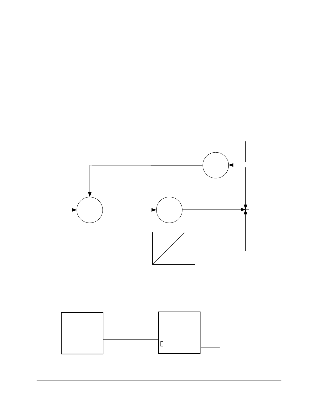
Master/Slave Arrangement
Introduction
With the motor positioner, the controlling signal for the actuator is a 4 mA to 20 mA from a current output
controller as shown in the flow diagram in Figure 25.
Unlike
the position output controller, the current output controller must produce a continuous analog signal
or the actuator will revert to one of its failsafe states. Signal failure is not a problem since the available
failsafe settings allow you to set the actuator position on signal loss.
Basic Flow Control
When the process variable signal is below set point, the controller increases current (4 mA to 20 mA) to the
actuator input and opens the valve. Controller set point governs valve position to obtain desired flow rate.
6. Control Applications - Master/Slave Arrangement
Orifice P late
PV
Controller
SP
FIC
Current Output Controller
4 to 20 mA
Positioner & Actuator
MP
Position
mA
Figure 25 Flow Diagram
10260S Series Actuator
FT
Valve
Linkage
+
4 to 20 mA
-
250 Ohms
1 to 5 VDC
Hot
Neutral
Ground
120/240
VAC
Figure 26 Interconnection Diagram
Revision 5 10260S HercuLine® Actuator Installation, Operation and Maintenance Manual 79
7/07
Page 90
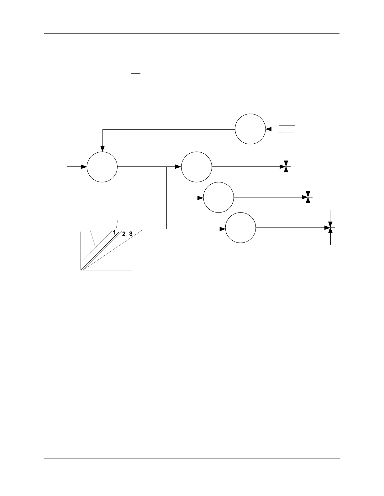
6. Control Applications - Master/Slave Arrangement
Proportional Flow using Multiple Actuators
Refer to flow diagram in Figure 27 and interconnection diagrams in Figure 28. The controller governs flow
rate in one burner. Only that
flow is measured. Since #2 and #3 motor positions receive the same signal as
#1 motor positioned, valves #2 and #3 will deliver the same amount of fuel. This is true when the span and
zero adjustment are all set the same as in curve 2 of the graph. Other relationships between units exist if
the span adjustment (3) for ratio or if the zero adjustment is changed (1) for bias.
Orifice Plate
SP
Position
FIC
with Bias
mA
PV
Positioner & Actuator
Controller
4 to 20 mA
Proportional
MP
#1
Ratio
Linkage
MP
#2
Linkage
MP
#3
Figure 27 Proportional Flow Using Multiple Actuators
FT
Valve
Linkage
Valve
Valve
80 10260S HercuLine® Actuator Installation, Operation and Maintenance Manual Revision 5
7/07
Page 91
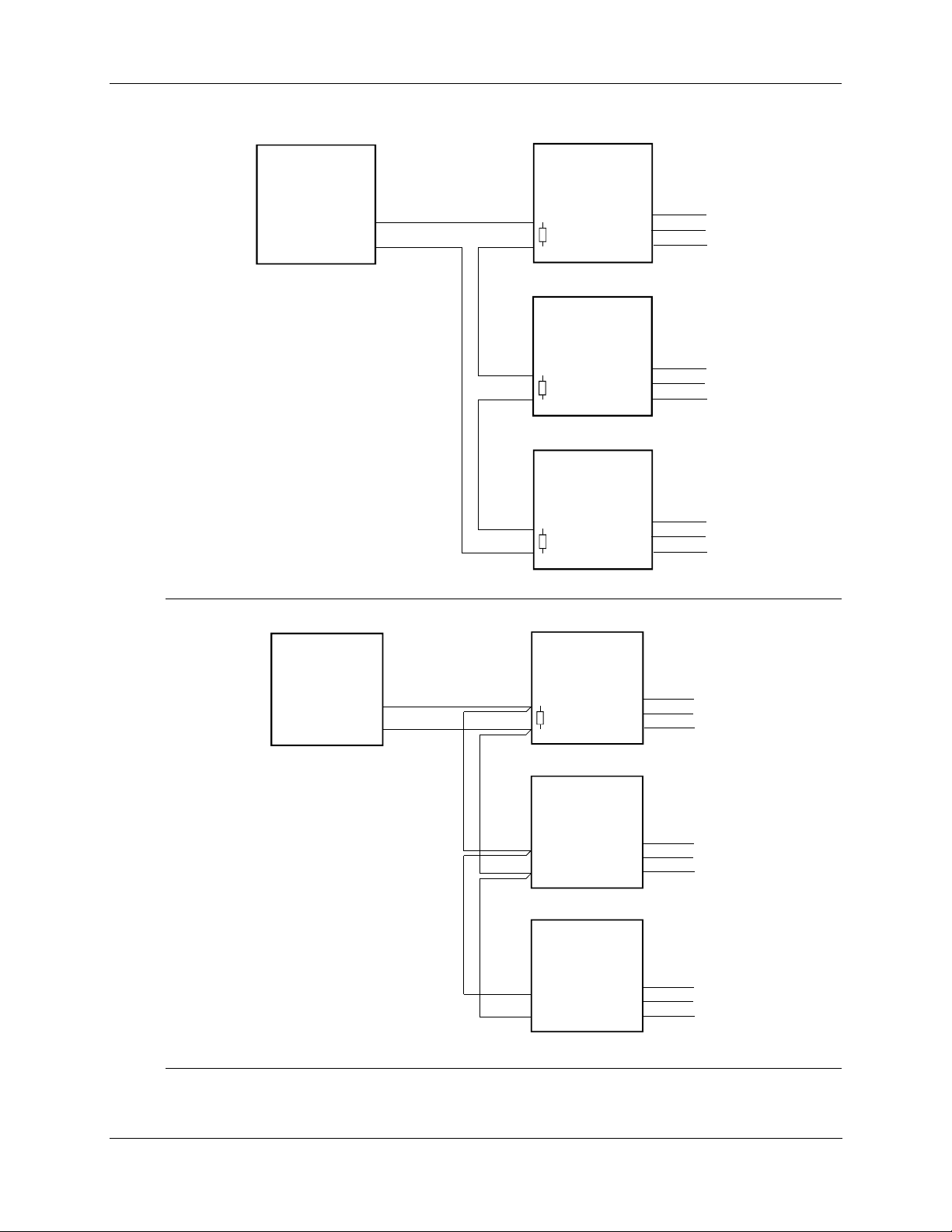
6. Control Applications - Master/Slave Arrangement
Current Output Controller
+
4 to 20 mA
-
Note: Controller must
be capable of sourcing
the impedance.
Preferred
Wiring
NOTE: If using HART communications, for this application HART must be configured for Multi-drop operation.
10260S Series Actuator #1
Hot
250 Ohms
1 to 5 VDC
10260S Series Actuator #2
250 Ohms
1 to 5 VDC
10260S Series Actuator #3
250 Ohms
1 to 5 VDC
Neutral
Ground
Hot
Neutral
Ground
Hot
Neutral
Ground
120/240
VAC
120/240
VAC
120/240
VAC
Current Output Controller
+
4 to 20 mA
-
Alternate
Wiring
10260S Series Actuator #1
Hot
250 Ohms
1 to 5 VDC
10260S Series A c tua t or #2
10260S Series A c tua t or #3
Neutral
Ground
Hot
Neutral
Ground
Hot
Neutral
Ground
120/240
VAC
120/240
VAC
120/240
VAC
NOTE: If using HART communications, for this application HART must be configured for Multi-drop operation.
Figure 28 Multiple Actuator Interconnection Diagrams
Revision 5 10260S HercuLine® Actuator Installation, Operation and Maintenance Manual 81
7/07
Page 92
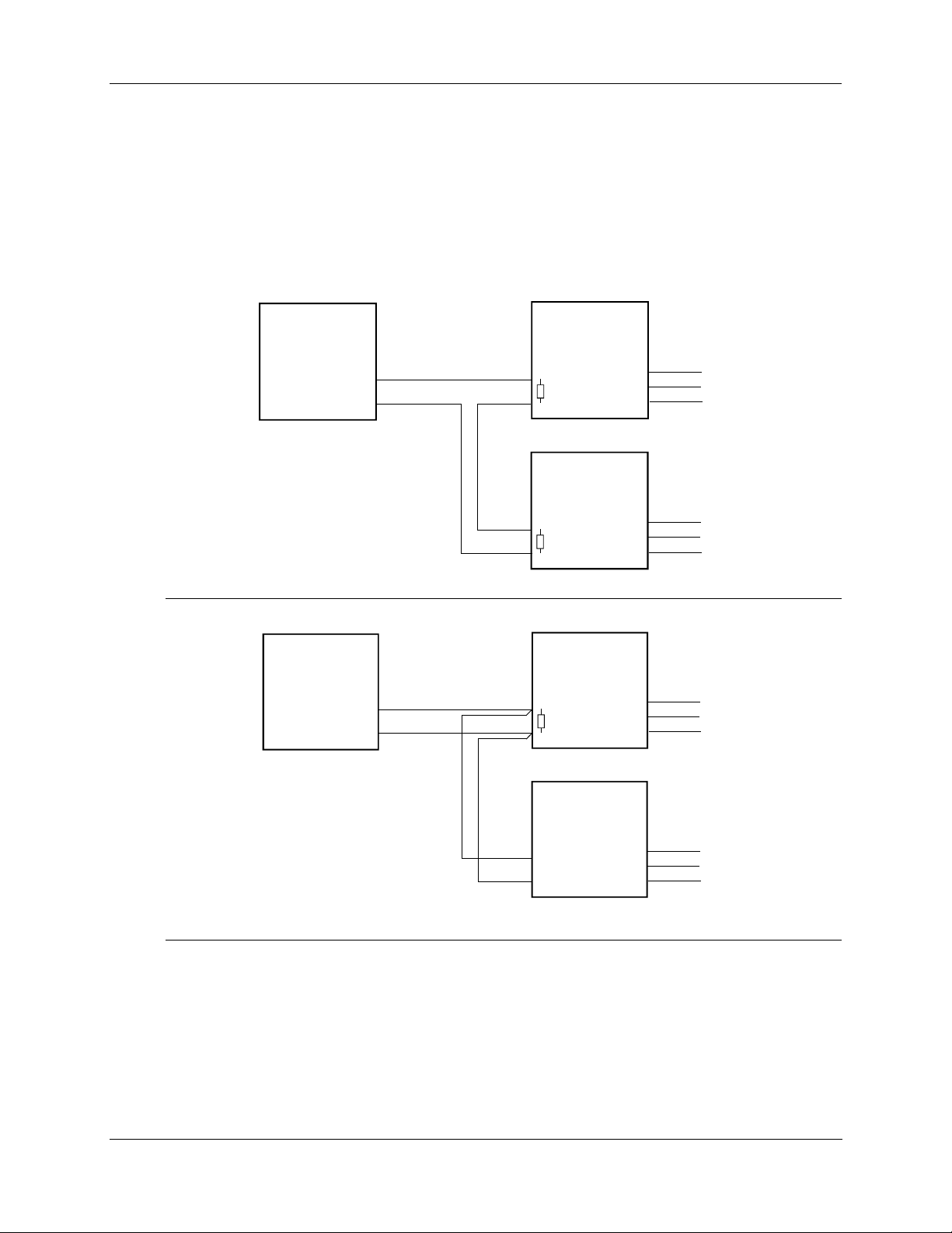
6. Control Applications - Master/Slave Arrangement
Split Valve Configuration
A common heat or cool type process requires two valves. In this case the controller has only one output.
The two motor positioners are calibrated differently, one responds to 4 mA to 12 mA and the other
responds to 12 mA to 20 mA. At 12 mA both valves are closed, one opening below 12 mA and the other
above 12 mA. Refer to Figure 29 for an interconnection
actualtors.
diagram for split valve operation using two
Current Output Controller
+
4 to 20 mA
-
Note: Controller must
be capable of sourcing
the impedance.
Preferred
Wiring
NOTE: If using HART communications, for this application HART must be configured for Multi-drop operation.
Current Output Controller
+
4 to 20 mA
-
10260S Series Actuator #1
Hot
250 Ohms
1 to 5 VDC
10260S Series Actuator #2
250 Ohms
1 to 5 VDC
10260S Series Actuator #1
250 Ohms
1 to 5 VDC
Neutral
Ground
Hot
Neutral
Ground
Hot
Neutral
Ground
120/240
VAC
120/240
VAC
120/240
VAC
10260S Series Actuator #2
Alternate
Wiring
Hot
Neutral
Ground
120/240
VAC
NOTE: If using HART communications, for this application HART must be configured for Multi-drop operation.
Figure 29 Interconnection Diagrams
82 10260S HercuLine® Actuator Installation, Operation and Maintenance Manual Revision 5
7/07
Page 93

6. Control Applications - Master/Slave Arrangement
Revision 5 10260S HercuLine® Actuator Installation, Operation and Maintenance Manual 83
7/07
Page 94

Page 95

Introduction
There is some basic maintenance that is recommended for the 10260S Series Smart Actuators. The
electronic PWAs within the actuator require no maintenance or servicing under normal conditions.
If there is a problem, refer to information in this section as well as Section 9 – Troubleshooting.
Basic Maintenance
Non-Contact Sensor
Under normal conditions the non-contact sensor PWA does not require maintenance.
Main Gear Lubrication
Under normal operating conditions, the main worm gear should not require maintenance.
7. Maintenance - Basic Maintenance
7. Maintenance
Spur Gear Lubrication
Honeywell recommends that during major shutdown periods the spur gears should be inspected and
lubricated. Follow the steps in Table 31 to access the spur gear com
necessary.
WARNING
Disconnect power before opening the actuator case to inspect the actuator gears. A
potentially dangerous pinch hazard exists inside the case if the unit is opened while powered.
Step Action
1
Remove AC power from actuator.
2
Remove the six screws and the side cover of the actuator case. See Figure 30.
3
Inspect the final spur gear, the idler gear and motor pinion for excessive wear and adequate
lubrication. See Figure 30.
4
If needed, use Texaco Starplex 2 EP grease, or equivale nt and apply lubricant to assure that
the gears are adequately protected.
partment and lubricate the gears if
Table 31 Spur Gear Lubrication Procedure
5
Install a new gasket and replace side cover. Secure to actuator with screws.
6
Restore actuator to service.
Revision 5 10260S HercuLine® Actuator Installation, Operation and Maintenance Manual 85
7/07
Page 96
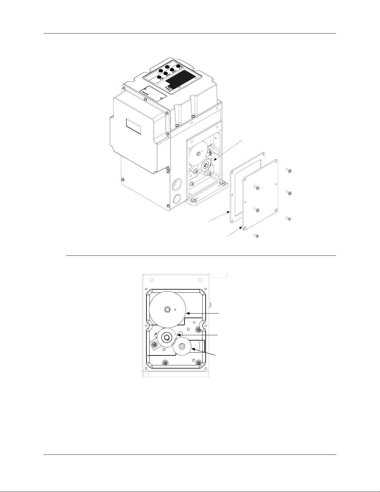
7. Maintenance - Basic Maintenance
Spur Gears
Side Cover
Gasket
Side Cover
Final Spur
Gear
Idler Gear
Motor Pi nion
Figure 30 Spur Gear Location
86 10260S HercuLine® Actuator Installation, Operation and Maintenance Manual Revision 5
7/07
Page 97
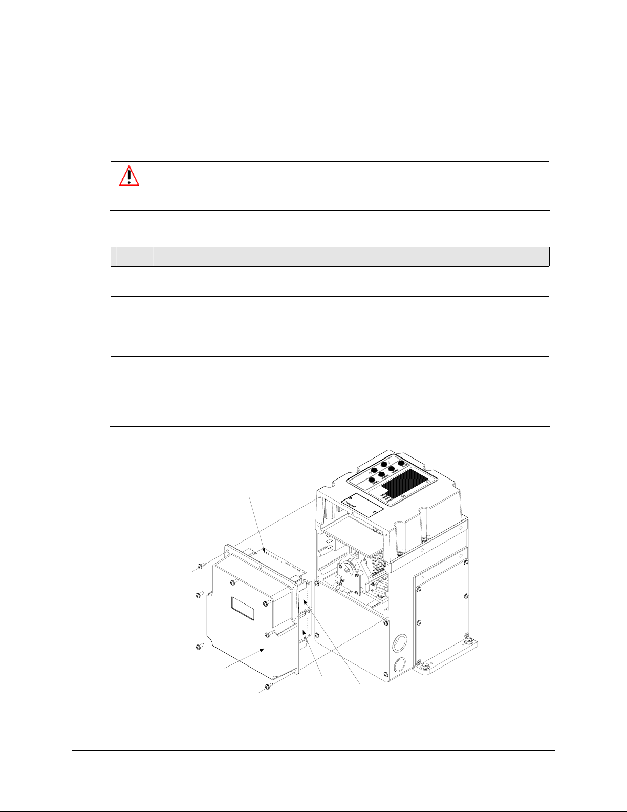
Replacement Procedures
Fuse Replacement
The motor drive circuit contains two fuses. They are locate d on the powe r distribution PWA. If it becomes
necessary to replace these fuses, follow the procedure in Table 32 and refer to Figure 32 for fuse location.
WARNING
Disconnect power before opening the actuator case to replace the fuse(s). A potentially lethal
shock hazard exists inside the case if the unit is opened while powered.
Table 32 Motor Drive Fuse Replacment Procedure
Step Action
1
Remove AC power from actuator.
2
Remove the seven screws and the extended cover of the actuator case. See Figure 31.
3
Lay assembly down on a flat surface and remove old gasket.
7. Maintenance - Replacement Procedures
4
Locate the two fuses on the power distribution PWA. See Figur e 32. Carefully remove and
replace fuse(s) with Wickmann T1 type 6A 250V, or equivalent.
5
Install a new gasket and replace extended cover. Secure to actuator with screws.
Power
Distribution
PWA
Extended
Cover Assembly
Relay 3 and 4
PWA
Relay 1 and 2
PWA
Figure 31 Power Distribution PWA and Relay PWA Locations
Revision 5 10260S HercuLine® Actuator Installation, Operation and Maintenance Manual 87
7/07
Page 98
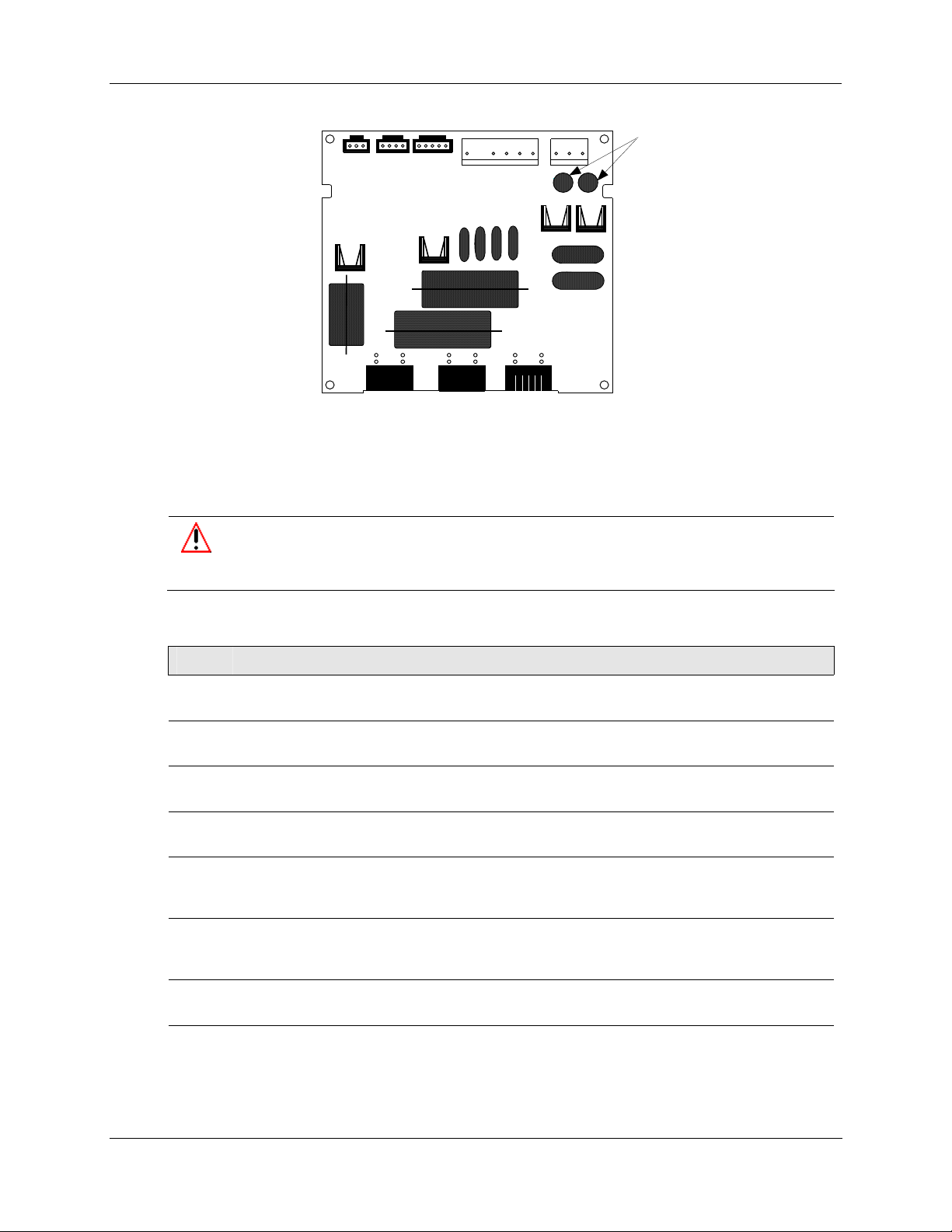
7. Maintenance - Replacement Procedures
Power Dis tr i buti on PWA
Figure 32 Motor Drive Circuit Fuses
Relay PWA Replacement
If a relay PWA needs to be replaced, follow the procedure in Table 33 to access and replace the PWA.
WARNING
Disconnect power before opening the actuator case. A potentially lethal shock hazard exists
inside the case if the unit is opened while powered.
Table 33 Relay PWA Replacement Procedure
Fuses for
Motor Driv e
Circuit
Step Action
1
Remove AC power from actuator.
2
Remove the seven screws and the extended cover of the actuator case. See Figure 31.
3
Lay assembly down on a flat surface and remove old gasket.
4
Disconnect the wire connector from the relay PWA.
5
Carefully remove the relay PWA. Turn the locking tabs of the card guides away to unlock the
PWA and slide it out from the card guides.
6
Install the replacement relay PWA by sliding it into the card gui des until it mates with the Main
CPU. Turn the locking tabs on the card guides to secure the PWA in place.
7
Plug in wire connector to relay PWA.
8 Install a new gasket and replace extended cover. Secure to actuator with screws.
88 10260S HercuLine® Actuator Installation, Operation and Maintenance Manual Revision 5
7/07
Page 99
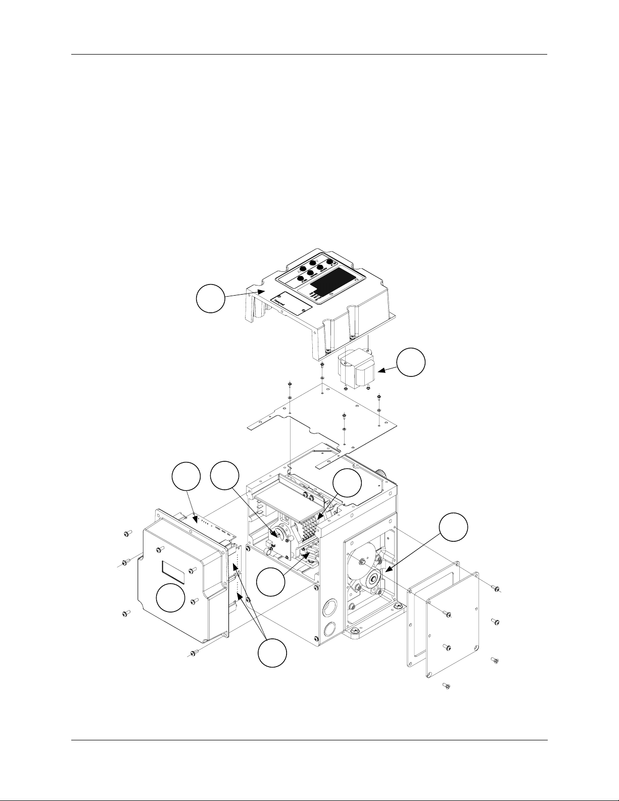
8. Replacement/Recommended Spare Parts
Introduction
This section provides you with a complete list of all the spare parts that may be needed for the 10260S
Series Actuators and optional equipment. Each kit contains replacement parts accessories and instructions
for component replacement. The numbers in Figure 33 identify the location
replacement components and are keyed to parts kits listed in this section.
8. Replacement/Recommended Spare Parts -
of various actuator
5
7
6
2
9
1
8
4
3
Figure 33 10260S Actuator Components
Revision 5 10260S HercuLine® Actuator Installation, Operation and Maintenance Manual 89
7/07
Page 100

8. Replacement/Recommended Spare Parts -
Motor Kits
Kit #51205551-501 Motor 1026(1, 2, 4, 6) 120 V 50/60 Kit
Part Description
Motor
Capacitor, Motor 7.5uf
Gasket Set (10260S)
Kit Instruction
Kit #51205551-502 Motor 10263 120 V 50/60 Kit
Part Description
Motor
Capacitor, Motor 11uf - 60 Hz
Capacitor, Motor 13uf - 50 Hz
Gasket Set (10260S)
Kit Instruction
Kit #51205551-503 Motor 1026(7, 8, 9) 120 V 50/60 Kit
Part Description
Motor
Capacitor, Motor 14uf
Gasket Set (10260S)
Kit Instruction
Kit #51205551-504 Motor 1026(1, 2, 4, 6, 7, 8, 9) 240 V 50/60 Kit
Part Description
Motor
Capacitor, Motor
Capacitor, Motor
Gasket Set (10260S)
Kit Instruction
Kit #51205551-505 Motor 10263 240 V 50/60 Kit
Part Description
Motor
Capacitor, Motor
Capacitor, Motor
Gasket Set (10260S)
Kit Instruction
90 10260S HercuLine® Actuator Installation, Operation and Maintenance Manual Revision 5
7/07
 Loading...