

Page 1
L41../L61.. SERIES
THERMOSTAT (AQUASTAT)
PRODUCTION HANDBOOK
APPLICATION
The L41../L61.. series aquastats are primarily designed for
application on water filled heating systems and systems for hot
water supply, mainly domestic use.
Subject to change without notice. All rights reserved.
Contents
General page
Description of device functions .........................................2
Description ........................................................................ 3
Overview/selection guide ................................................. 4
Features ............................................................................5
Aquastat series
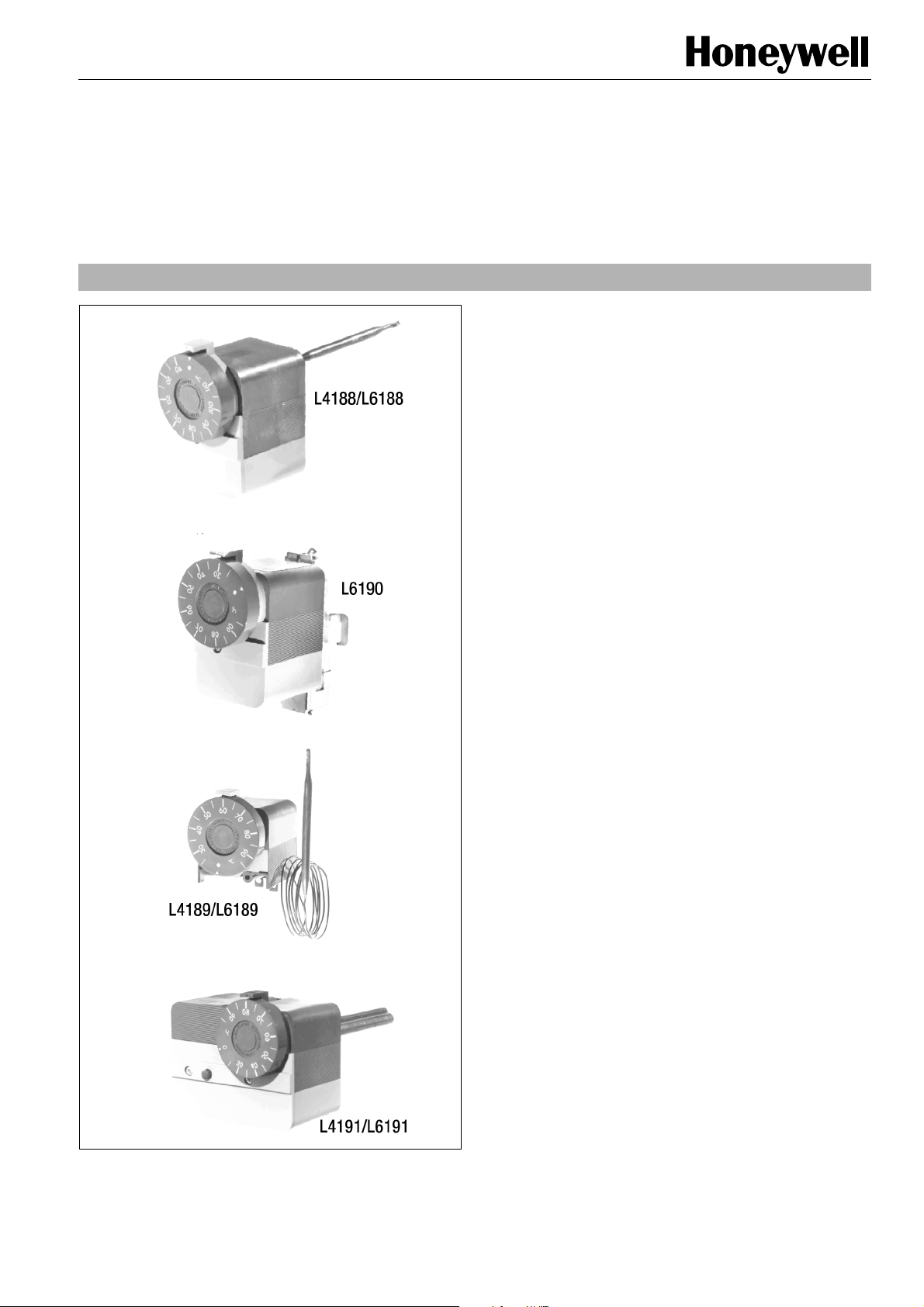
L4188 - L6188 .................................................................. 6
L4189 - L6189 .................................................................. 8
L6190 ............................................................................. 10
L4191 - L6191 ................................................................ 12
L6188A 2044 Tradeline .................................................. 14
Performance .................................................................... 16
Construction .................................................................... 17
Various
Accessories and spare parts ........................................... 18
Quality assurance statement ........................................... 20
Standards and approvals ................................................ 20
Ordering information ........................................................21
1 EN2R-9005 0406R3-NE
Page 2

DESCRIPTION OF DEVICE FUNCTIONS
Aquastats thermostats
Honeywell manufactures a coprehensive range of water
temperature thermostats (trade name Aquastat) for controlling
and limiting boiler water temperature in hydronic heating
systems.
These sensitive, fast response devices are available in either
direct, panel or surface mount versions.
Sensing element
The liquid filled sensing element, including well or sensor
assembly, responds to temperature changes of water in a
heating system.
The sensor element has a diaphragm type power head
connected to a tube type capsule, through a small bore
capillary.
Expansion of the liquid, which completely fills the sensing
element, is the means of motion of the diaphragm.
The sensor assembly, used on the surface mounted aquastat,
envelopes the sensing capsule by means of an aluminium
heat shield for better heat conduction, an insulator of
glasswool and a mounting bracket.
Control mechanism
The control mechanism is mounted into the thermoplastic
housing. The mechanism transfers the motion of the
diaphragm to a snap action switch (Micro Switch) and also
provides the facility to adjust the temperature level on which
the Micro Switch has to operate.
The mechasnism consists of a two piece lever with calibration
screw, a plastic actuator for the switch, a cam and shaft for the
set-point adjustment, a loading spring for cam and levers and
a pad with pushplate to transfer the diaphragm motion to the
lever.
Knob with scale and index
The plastic knob with scale and index enables the user to
adjust the Aquastat on a selected temperature setting within
its range. The knob fits on the cam and stays on it due to the
force of the spring on the nave of the knob.
This spring force enables the installer to pull the knob from the
cam without the use of tools.
The hole in the knob and the shaft of the cam are provided
with a flat side which allows mounting of the knob only in one
position in order to maintain the calibration.
The plastic index will be fastened by means of two M4 thread
forming screws on the housing.
Micro Switch
The Micro Switch mechanism is also mounted into the plastic
housing. the mechanism consists of a snap action spring type
PL with contacts and a moveable or a fixed and a stationary
contact bracket.
The Micro Switch mechanism is intended to control electrically
a burner, a relay, etc. in dependency of the temperature
changes in a heating system.
On choice the Micro Switch mechanism can be delivered with
the following contact arrangements:
• Single Pole Single Throw,
C-1 breaks on temperature rise
• Single Pole Double Throw,
C-1 breaks on temperature rise.
C-2 makes on temperature rise.
The contacts are connected to 6.3 mm terminals which are
extending from the outside of the Aquastat housing.
Cover and conduit entries
The housing(s) of the Aquastat can be provided with conduit
boxes which are provided with holes to fit Pg 13.5 conduits.
To obtain easy wiring possibilities these boxes can be
mounted or disconnect without the use of tools (hook in
approach).
The conduit box is locked with the front cover, which is
fastened by means of an M3 thread forming screw. Also the
top cover is locked by the front cover.
Set-point stops
On request, the Aquastat can be delivered with a high and low
limit stop. The purpose of these stops is to provide the user
with the facility to choose a maximum and/or minimum setting
on the scale.
The stop is situated on the rear side of the setting knob.
Adjustment is only possible after removal of the knob.
Manual or tool reset
On request, the Aquastat can be delivered with a manual reset
or a tool reset feature.
The tool reset feature is covered by the front cover.
Operating of the reset button is only possible after removal of
the front cover.
The manual reset button potrudes the front cover of the
Aquastat and resetting can be done without the use of a tool.
Adjustable differential
On request, it is possible to deliver the Aquastat with an
adjustable switch differential.
The adjustable switch differential feature consists of a plastic
adjusting dial with pointer, which is connected to a moveable
contact.
Turning of the dial changes the contact gap of the Micro
Switch and thus the differential.
The dial is situated under the front cover or behind the panel.
Adjustable differential feature is only applicable on controllers
and recycling limit controls
EN2R-9005 0406R3-NE 2
Page 3

DESCRIPTION
The L41../L61.. series aquastats are sensitive water temperature control, which are provided with a liquid filled sensing system.
The following main types are available:
• Single, panel mount immersion
Aquastat with remote bulb to select the most favourable
position on a boiler or vessel.
• Single, direct mounted immersion
Aquastat with insulating cover to protect against accidential
touching of live parts.
• Dual, direct mounted immersion
Dual Aquastat and consisting of two basic single units,
which are mounted together and protected by one common
cover and using one well for the two sensors.
• Single, surface mounted
The sensor of this type is to be mounted directly on the
surface of a boiler or pipe in a heating system. The
Aquastat mechanism is directly attached to this sensor.
The L41../L61.. series aquastats are primarily designed for
application on water filled heating systems and systems for hot
water supply, mainly domestic use.
The L41../L61.. series aquastats can be divided in the
following main types:
• Controller
Controls the water temperature in accordance with the
setting of an external knob (TÜV-type TR)
• Recycling limit control
Limits the water temperature below or above an adjusted
level and resets automatically. This type has a greater
differential and no external knob (TÜV-type TW).
• Thermal cut-out with external reset button
(manual reset)
Limits the water temperature on a maximum adjusted level.
This type does not reset automatically and it does not have
an external knob.
• Thermal cut-out with internal reset button (tool reset)
Limits the water temperature on a maximum adjusted level.
This type does not reset automatically and it does not have
an external knob.
3 EN2R-9005 0406R3-NE
Page 4
OVERVIEW/SELECTION GUIDE
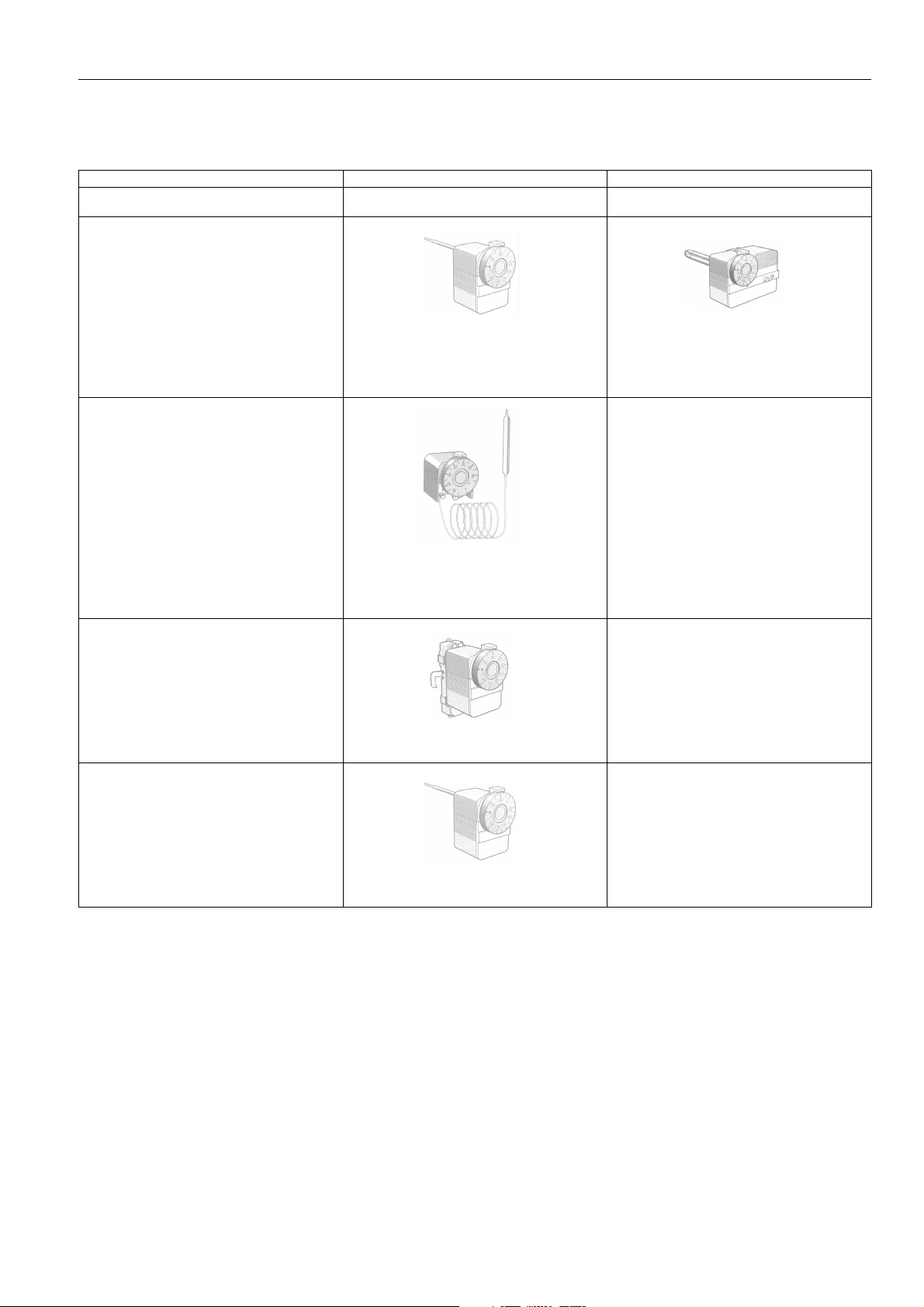
Application Single Aquastat thermostats Dual Aquastat thermostats
Controller or limiter thermostat Controller and limiter thermostat with standard
Direct mount (immersion)
sensing element
Panel mount (immersion)
Surface mount
(with mounting strap)
Replacement aquastat (immersion)
L4188A, B, C
25 ... 95°C
40 ... 110°C
70 ... 140°C
L4189A, B, C 25 ...
95°C 40 ... 110°C
110 ... 230°F
L6190A, B, C
25 ... 95°C
L6188A, B, C
25 ... 95°C
40 ... 110°C
70 ... 140°C
L6189A, B, C
25 ... 95°C
40 ... 110°C
70 ... 140°C
110 ... 230°F
L4191A, B and L6191A, B
25 ... 95°C
50 ... 95°C
40 ... 110°C
70 ... 140°C
L6188A 2044
40 ... 110°C
EN2R-9005 0406R3-NE 4
Page 5

FEATURES
• 6.3 mm quick connect terminals for receptacles
• Mounting either in a horizontal or vertical position.
• Housing is provided with two mounting holes which are
suitable for M4 thread forming screws, for mounting on a
control panel.
• Cable entry in the conduit box is suitable for Pg 13.5
conduit or is provided with a plastic grommet (at choice).
• The high and low setpoint stops are field adjustabe with
steps of 2.5°C.
• Capillary available in 350 mm (optional), 1000 mm
(standard), 1500 mm (optional) and 2000 mm (optional)
length.
• Surface mounted Aquastat can be mounted on
cylinders of 300 ... 460 mm diameter as well on pipes
from 40 ... 150 mm diameter.
• Wide range of well assemblies available.
5 EN2R-9005 0406R3-NE
Page 6
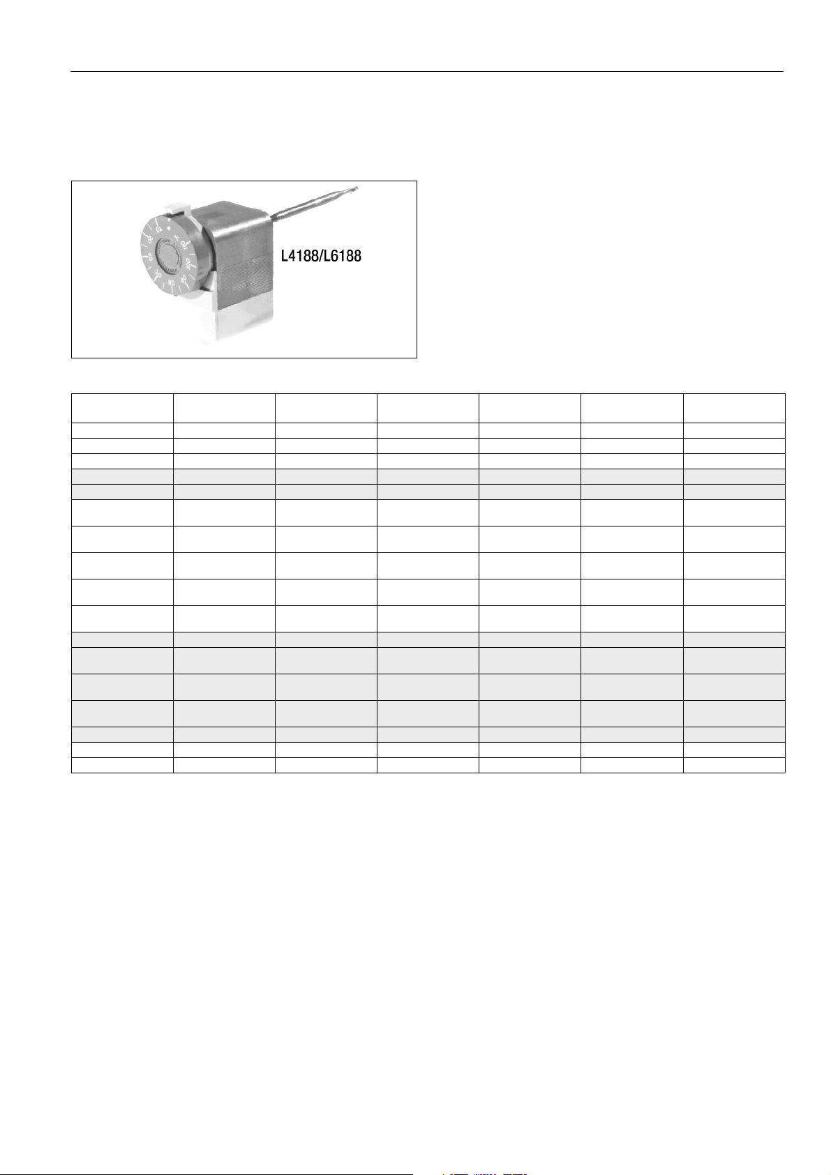
L4188 - L6188 SINGLE AQUASTAT - DIRECT IMMERSION
APPLICATIONS AND ORDERING INFORMATION
Application
L4188 and L6188 are sensitive, immersion-type water
temperature thermostats for controlling and limiting boiler
water temperature in hydronic heating systems.
The thermostat has a liquid-filled sensing element which fits
into an immersion well (order separately) for direct mounting
into a boiler, tank or other vessel.
Ordering information
O.S. number Application Temperature
range
L4188A 2015 Controller 25 ... 95°C 4 SPST External knob L4188A 2023 Controller 40 ... 110°C 4 SPST External knob 5
L4188A 2031 Controller 25 ... 95°C 4 SPST External knob 5
L4188B 2005 Controller 40 ... 110°C 4 SPST Internal screw 4 - 5
L4188B 2013 Controller 25 ... 95°C 4 SPST Internal screw 4 - 5
L6188A 2002 Controller 25 ... 95°C
L6188A 2010 Controller 40 ... 110°C
L6188A 2028 Controller 25 ... 95°C
L6188A 2036 Controller 70 ... 140°C
L6188A 2044 Controller 40 ... 110°C
L6188B 2000 Controller 25 ... 95°C 4 SPDT Internal screw 4
L6188B 2018 Controller 70 ... 140°C
L6188B 2026 Controller 40 ... 110°C
L6188B 2034 Controller 25 ... 95°C
L6188B 2042 Controller 25 ... 95°C 4 SPDT Internal screw
L6188C 2008 Limiter 70 ... 140°C Manual reset SPDT Internal screw 7
L6188C 2016 Limiter 25 ... 95°C Manual reset SPDT Internal screw 6 - 7
Switch
differential (K)
4 ... 10
(adjustable)
4 ... 10
(adjustable)
4 ... 10
(adjustable)
4 ... 10
(adjustable)
4 ... 10
(adjustable)
4 ... 10
(adjustable)
4 ... 10
(adjustable)
4 ... 10
(adjustable)
Switch type Setting means Remarks
(see notes)
SPDT External knob 6
SPDT External knob 6
SPDT External knob 3
SPDT External knob 6
SPDT External knob Tradeline 1 - 7
SPDT Internal screw 3 - 7
SPDT Internal screw
SPDT Internal screw 6 - 7
1 = High limit stop
2 = High limit stop at 60°C
3 = Capilliary length 1500 mm and mounting bracket
4 = Without cover and conduit box
5 = Quick connect terminals only
6 = With well assembly
7 = With push-in plug
EN2R-9005 0406R3-NE 6
Page 7
L4188 - L6188 SINGLE AQUASTAT - DIRECT IMMERSION
Specifications
Ambient temperature limits
0 ... 70°C
Electrical connection
6.3 mm spade terminals
Enclosure
IP40
Electrical rating
10 A at 250 Vac, resistive load
2.5 A at 250 Vac, inductive load
15 A at 250 Vac, locked motor
250 mA at 30 mVdc (special option)
Ter minal data
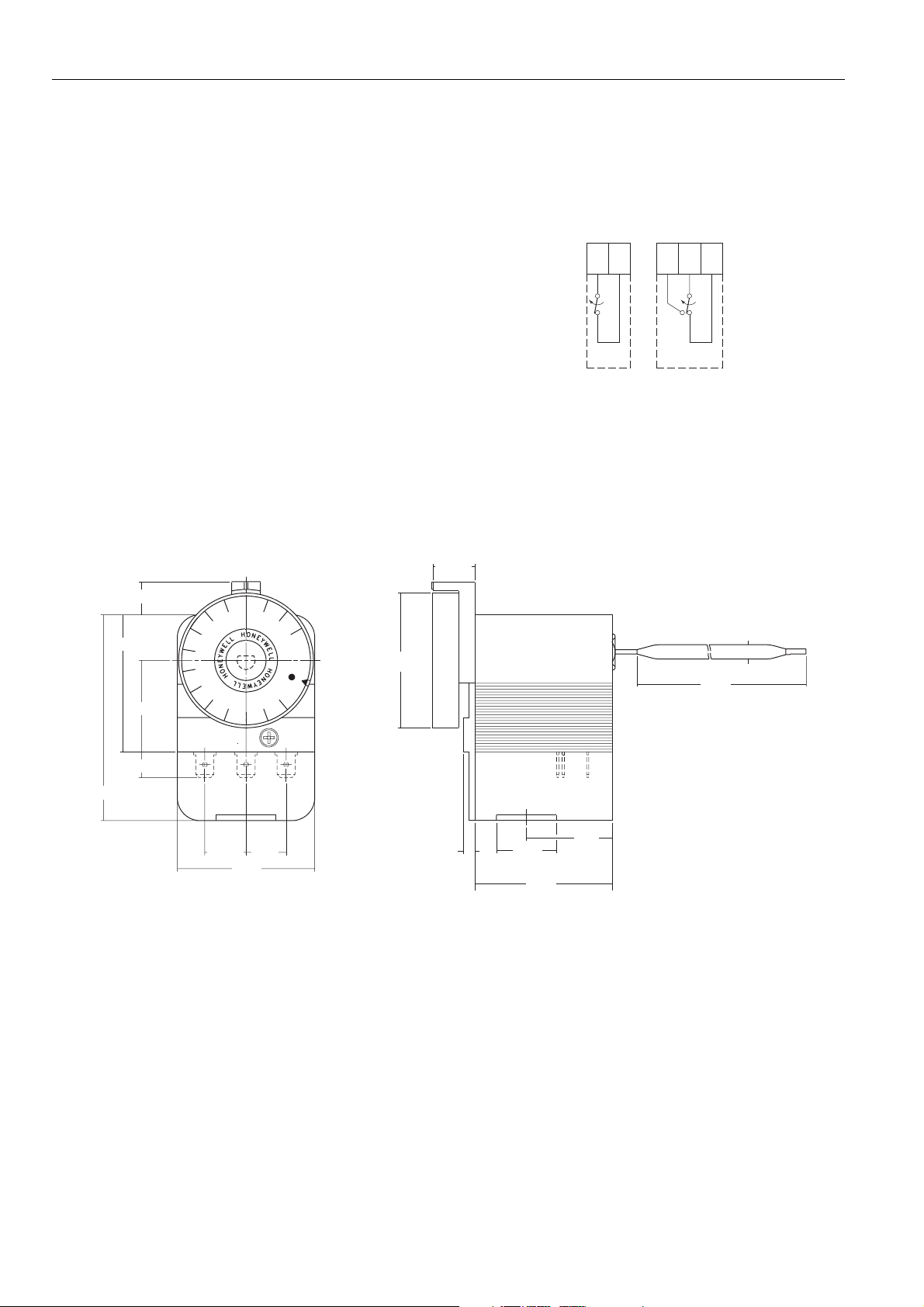
C-1 breaks on temperature rise (SPDT and SPST)
C-2 makes on temperature rise (SPDT only)
Accessories
11.5
11.5
48
32
47.1
Immersion wells, see page 18
Fig. 1. Internal schematics L4188/L6188
14.6
C+1 C
SPDTSPST
12
+
5
85
72
9
14.4
14
48
C12
4
21
Pg 13.5
48
30
Fig. 2. Dimensional drawing L4188/L6188
7 EN2R-9005 0406R3-NE
Page 8
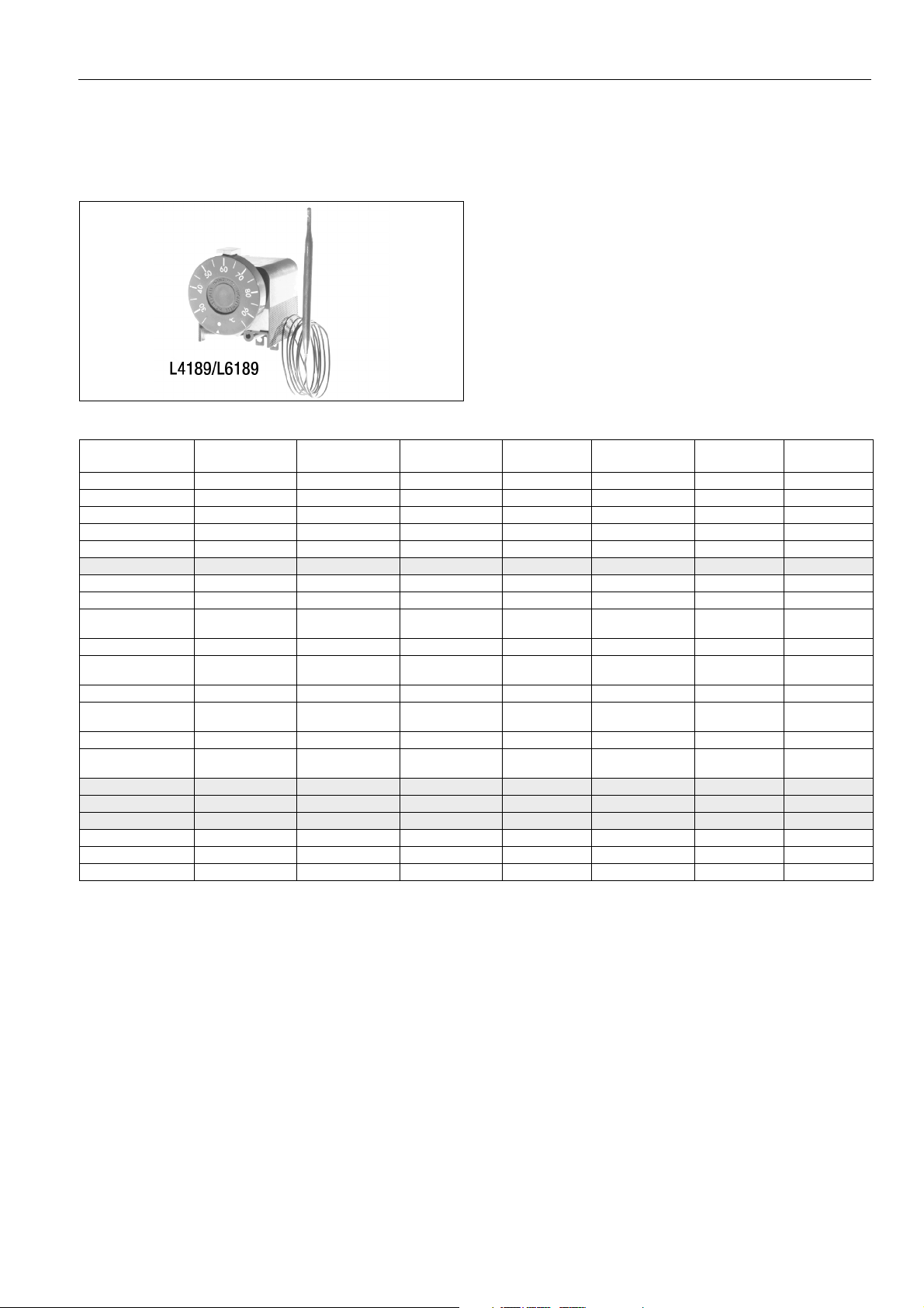
L4189 - L6189 SINGLE AQUASTAT - PANEL MOUNTING (IMMERSION)
APPLICATIONS AND ORDERING INFORMATION
Application
L4189 and L6189 are sensitive, immersion-type water
temperature thermostats for controlling and limiting boiler
water temperature in hydronic heating systems.
These thermostats are designed for panel mounting and are
supplied with a remote bulb and a liquid-filled sensing element
which fits into an immersion well (order separately) for
mounting into a boiler, tank or other vessel.
Ordering information
O.S. number Application Temperature
range
L4189A 2006 Controller 25 ... 95°C 4 SPST External knob 1000 2
L4189A 2014 Controller 25 ... 95°C 4 SPST External knob 1500 L4189A 2089 Controller 25 ... 95°C 4 SPST External knob 1000 1 - 4 - 5
L4189A 2097 Controller 25 ... 95°C 4 SPST External knob 1000 5
L4189A 2105 Controller 25 ... 95°C 4 SPST External knob 350 1 - 6
L4189B 2012 Controller 100 ... 230°F 4 SPST Internal screw 1000 3
L6189A 2001 Controller 25 ... 95°C 8 SPDT External knob 1500 2
L6189A 2019 Controller 25 ... 95°C 4 SPDT External knob 1500 -
L6189A 2043 Controller 40 ... 110°C
L6189A 2068 Controller 25 ... 95°C 4 SPDT External knob 1000 2
L6189A 2092 Controller 110 ... 230°F
L6189A 2118 Controller 110 ... 230°F15°F SPDT External knob 1500 1
L6189A 2134 Controller 110 ... 230°F
L6189A 2142 Controller 110 ... 230°F15°F SPDT External knob 2000 1
L6189A 2159 Controller 110 ... 230°F
L6189B 2009 Controller 25 ... 95°C 4 SPDT Internal screw 1000 -
L6189B 2025 Controller 25 ... 95°C 4 SPDT Internal screw 1000 2, Tradeline
L6189B 2041 Controller 40 ... 110°C 8 SPDT Internal screw 1500 -
L6189C 2007 Limiter 40 ... 110°C Manual reset SPDT Internal screw 1500 L6189C 2023 Limiter 110 ... 230°F Manual reset SPDT External knob 1500 L6189C 2031 Limiter 110 ... 230°F Manual reset SPDT External knob 2000 -
Switch
differential (K)
4 ... 10
(adjustable)
7 ... 18°F
(adjustable)
7 ... 18°F
(adjustable)
7 ... 18°F
(adjustable)
Switch type Setting means Capillary
length (mm)
SPDT External knob 1500 -
SPDT External knob 1500 1
SPDT External knob 1500 1
SPDT External knob 2000 1
Remarks
(see notes)
1 = High limit stop
2 = Without knob and index
3 = With mounting bracket
4 = With conduit box
5 = With cable connector
6 = Low limit stop
EN2R-9005 0406R3-NE 8
Page 9

L4189 - L6189 SINGLE AQUASTAT - PANEL MOUNTING (IMMERSION)
SPECIFICATIONS AND DIMENSIONS
Specifications
Ambient temperature limits
0 ... 70°C
Electrical connections
6.3 mm spade terminals
Enclosure
IP40
Electrical rating
10 A at 250 Vac, resistive load
2,5 A at 250 Vac, inductive load
15 A at 250 Vac, locked motor
250 mA at 30 mVdc (special option)
Ter minal data
C-1 breaks on temperature rise (SPDT and SPST)
C-2 makes on temperature rise (SPDT only)
Capilliary length
350 mm, 1000 mm, 1500 mm and 2000 mm
Mounting hole (2) for M4x20
tread forming screw
32
16
Accessories
Immersion wells, see page 18
C+1 C
Fig. 3. Internal schematics L4189/L6189
17
48
2 mm max
12
+
SPDTSPST
60
Hole ( 4 min.) in
panel for tool reset
48
32
18
47.1
C12
1414.4
48
Panel
Fig. 4. Dimensional drawing L4189/L6189
28.5
30.5
85
5
9 EN2R-9005 0406R3-NE
Page 10
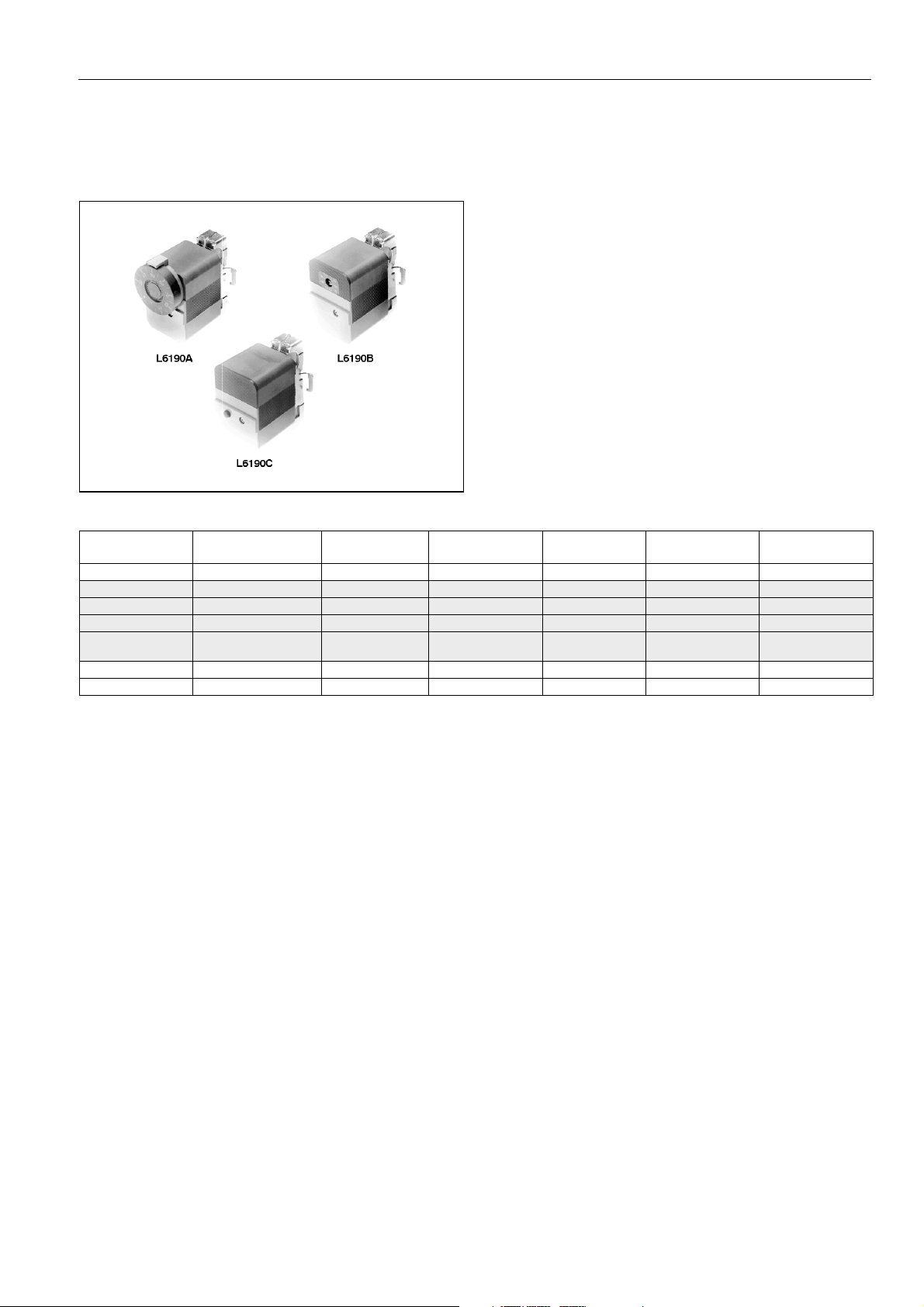
L6190 SINGLE AQUASTAT - SURFACE MOUNTING
APPLICATION AND ORDERING INFORMATION
Application
The L6190 is a sensitive water temperature thermostat
designed for surface mounting on domestic hot water cylinders
or pipe work. The SPDT switching action is accomplished by a
snap-action microswitch actuated by the temperature sensing
element.
The L6190 is supplied complete with mounting strap for rapid
and easy installation. Draining of the system or tapping of the
cylinder or pipe work is not required. The required temperature
control point is easily set using a screw driver.
Ordering information
O.S. number Application Temperature
range
L6190A 2016 Surface mounting 25 ... 95°C 8 SPDT External knob 250
L6190B 2006 Surface mounting 25 ... 95°C 8 SPDT External setting 2000
L6190B 2014 Surface mounting 25 ... 95°C 12 SPDT External setting 2000
L6190B 2022 Surface mounting 25 ... 95°C 4 SPDT External setting 2000
L6190B 2030 Surface mounting 25 ... 95°C
L6190C 2004 Surface mounting 25 ... 95°C Manual reset SPDT Internal setting 2000
L6190C 2012 Surface mounting 25 ... 95°C Manual reset SPDT Internal setting 2000
Switch
differential (K)
4 ... 10
(adjustable)
Switch type Setting means Strap length
(mm)
SPDT Internal setting 250
EN2R-9005 0406R3-NE 10
Page 11

L6190 SINGLE AQUASTAT - SURFACE MOUNTING
SPECIFICATIONS AND DIMENSIONS
Specifications
Ambient temperature limits
0 ... 70°C
Electrical connection
6.3 mm spade terminals or screw terminals
Enclosure
IP40
Electrical rating
10 A at 250 Vac, resistive load
2,5 A at 250 Vac, inductive load
15 A at 250 Vac, locked motor
Ter minal data
C-1 breaks and C-2 makes on temperature rise
26.5
Capilliary length
55 mm
C
12
+
SPDT
Fig. 5. Internal schematic L6190
48
24
6
6
12
72
100
92 9
30
51
24
Fig. 6. Dimensional drawing L6190
11 EN2R-9005 0406R3-NE
Page 12
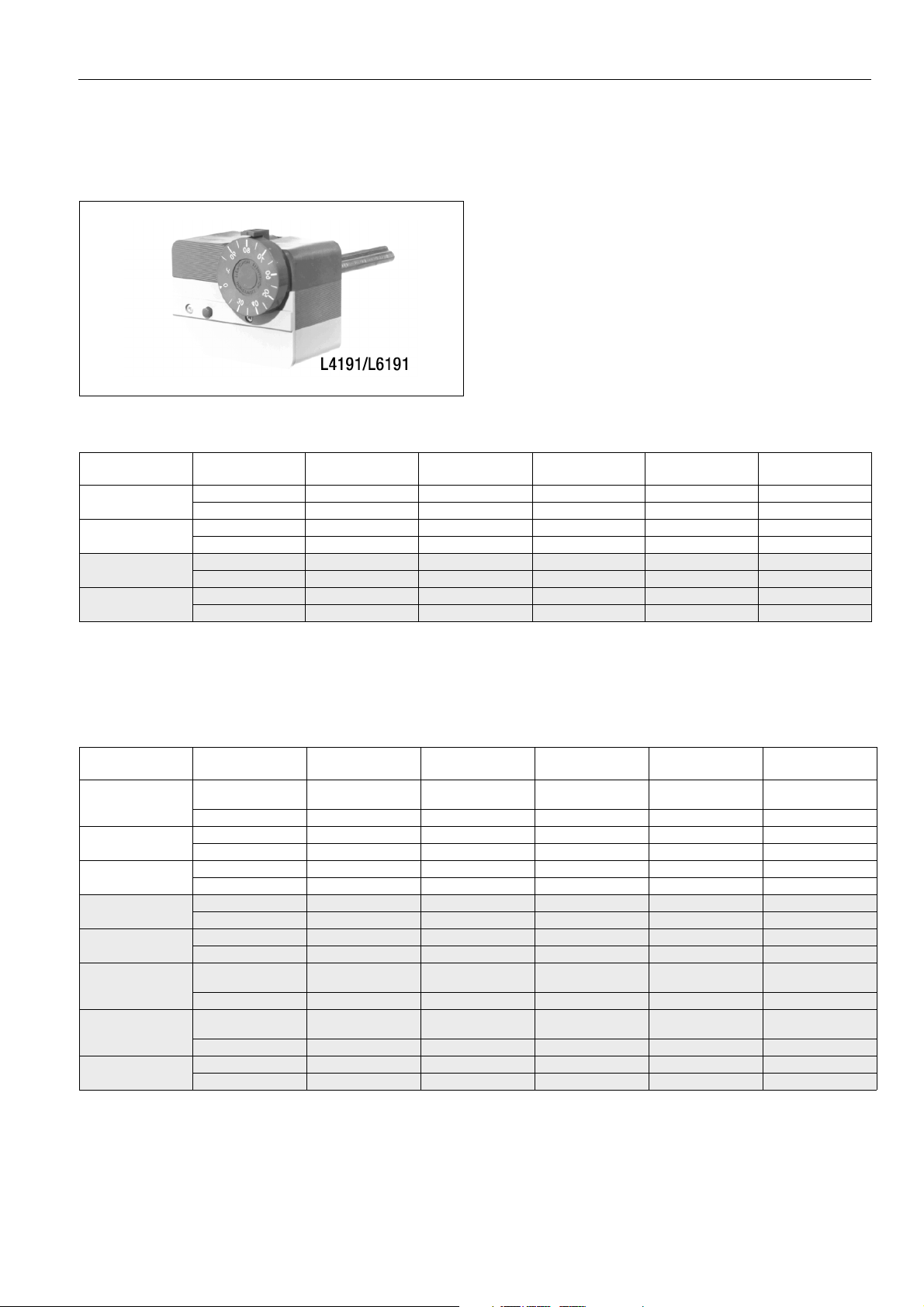
L4191 - L6191 DUAL AQUASTAT - DIRECT IMMERSION
APPLICATION AND ORDERING INFORMATION
Application
L4191 and L6191 are dual units in which two independently
working water temperature thermostats are housed in one
cover. Each thermostat has a separate liquid filled sensing
element which fits into a common immersion well for direct
mounting into a boiler, tank or other vessel. One thermostat,
with external temperature setting dial, acts as a controller
while the other, with internal setting dial, acts as a high limit
control.
Two main types are available, one with controller and auto
recycling high limit and the other with controller and high limit
with manual reset.
Ordering information L4191
O.S. number Application Temperature
L4191A 2002
L4191A 2010
L4191B 2018
L4191B 2042
Controller 25 ... 95°C 4 SPST External knob 9
Limiter 25 ... 95°C 4 SPST Internal screw 9
Controller 25 ... 95°C 4 SPST External knob 7 - 9 - 10
Limiter 25 ... 95°C 4 SPST Internal screw 9
Controller 70 ... 140°C 4 SPST External knob 6
Limiter 70 ... 140°C Manual reset SPDT Internal screw 1
Controller 25 ... 95°C 4 SPST External knob 5 - 9 - 10
Limiter 25 ... 95°C Manual reset SPDT Internal screw 9 - 10
range
Switch
differential (K)
Switch type Setting means Remarks
(see notes)
1 =Gold contacts for thermocouple applications, without jumper
2 =High limit stop at 80°C/low limit stop at 60°C
3 =High limit stop at 82°C
4 =Low limit stop at 95°C
5 =Isolated neutral terminal
6 =High limit stop at 95°C
Ordering information L6191
O.S. number Application Temperature
range
L6191A 2007
L6191A 2015
L6191A 2023
L6191B 2005
L6191B 2013
L6191B 2021
L6191B 2047
L6191B 2054
Controller 40 ... 110°C
Limiter 40 ... 110°C 4 SPDT Internal screw 9
Controller 25 ... 95°C 4 SPDT External knob 3
Limiter 101°C fixed 4 SPST Internal setting 1
Controller 50 ... 95°C 4 SPDT External knob 3
Limiter 101°C fixed 4 SPST Internal screw 1
Controller 25 ... 95°C 4 SPDT External knob 7 - 9 - 10
Limiter 40 ... 110°C Manual reset SPDT Internal screw 9
Controller 40 ... 110°C 4 SPDT External knob 5 - 6 - 7 - 9
Limiter 40 ... 110°C Manual reset SPDT Internal screw 9
Controller 70 ... 140°C
Limiter 70 ... 140°C Manual reset SPDT Internal screw 9
Controller 70 ... 140°C
Limiter 70 ... 140°C Manual reset SPDT Internal screw 9
Controller 25 ... 95°C 4 SPDT External knob 7 - 10
Limiter 50 ... 95°C Manual reset SPDT Internal screw
7 =With well assembly
8 =High limit stop
9 =With jumper
10 =With push-in plug
11 =Without knob and index
Switch
differential (K)
4 ... 10
(adjustable)
4 ... 10
(adjustable)
4 ... 10
(adjustable)
Switch type Setting means Remarks
(see notes)
SPDT External knob 6 - 7 - 9
SPDT External knob 4 - 7 - 9
SPDT External knob 4 - 7 - 9 - 11
1 =Gold contacts for thermocouple applications, without jumper
2 =High limit stop at 80°C/low limit stop at 60°C
3 =High limit stop at 82°C
4 = Low limit stop at 95°C
5 = Isolated neutral terminal
6 = High limit stop at 95°C
EN2R-9005 0406R3-NE 12
7 = With well assembly
8 = High limit stop
9 = With jumper
10 =With push-in plug
11 = Without knob and index
Page 13

L4191 - L6191 DUAL AQUASTAT - DIRECT IMMERSION
SPECIFICATIONS AND DIMENSIONS
Specifications
Ambient temperature limits
0 ... 70°C
C+1 C
Electrical connection
6.3 mm spade terminals
Enclosure
IP40
C+1
12C+1
+
Electrical rating:
10 A at 250 Vac, resistive load
2,5 A at 250 Vac, inductive load
15 A at 250 Vac, locked motor
250 mA at 30 mVdc (special option)
Ter minal data
C-1 breaks on temperature rise
C-2 makes on temperature rise
Accessories
Immersion wells, see page 18
11.5
72
ϕ 47.1
SPST
Control
C 12
SPDT
Control
14.6
SPST
Limit
C+1
+
SPDT
Limit
Fig. 7. Internal schematics
SPST
Control
C 12
+
SPDT
Control
SPDT
Limit
C 12
+
SPDT
Control
ϕ 5
85
84
4
Fig. 8. Dimensional drawing L4191/L6191
13 EN2R-9005 0406R3-NE
ϕ 21
Pg 13.5
48
30
Page 14

L6188A 2044 TRADELINE SINGLE AQUASTAT - DIRECT IMMERSION
APPLICATIONS AND ORDERING INFORMATION
Application
L6188A 2044 Tradeline Aquastat is a sensitive immersion-type
water temperature thermostat for regulating and limiting boiler
water temperature in hydronic heating systems.
The Honeywell Tradeline technique of using adapters enables
the L6188A 2044 Aquatat thermostat to field replace
Honeywell Aquastat thermostats as well as many competitive
devices (using the existing well*). No draining of the system is
needed. Ideal for service organisations to stock since only one
Aquastat is needed for most calls.
* If a new immersion well is needed order separately.
Ordering information L6188A 2044
O.S. number Application Temperature
range
L6188A 2044 Controller 40 ... 110°C
1 = High limit stop at 95°C/low limit stop at 50°C
Switch
differential (K)
4 ... 10
(adjustable)
Switch type Setting means Remarks
(see notes)
SPDT External knob 1
EN2R-9005 0406R3-NE 14
Page 15

L6188A 2044 TRADELINE SINGLE AQUASTAT - DIRECT IMMERSION
SPECIFICATIONS AND DIMENSIONS
Specifications
Temperature range
40 ... 110°C
Differential
4 ... 10 (adjustable)
Limit stops:
Low limit: adjustable, factory set at 50°C
High limit: adjustable, factory set at 95°C
Ambient temperature limits
0 ... 70°C
Electrical connection
6.3 mm spade terninals
Enclosure
IP40
Electrical rating
10 A at 250 Vac, resistive load
2,5 A at 250 Vac, inductive load
15 A at 250 Vac, locked motor
Ter m i n al data
C-1 breaks on temperature rise
C-2 makes on temperature rise
Accessories
Immersion wells, see page 18
C 12
+
SPDT
Fig. 9. Internal schematic
72
48
11.5
11.5
32
9
14.4
48
14
14.6
47.1
C12
4
Fig. 10. Dimensional drawing L6188A 2044
21
Pg 13.5
48
5
85
30
15 EN2R-9005 0406R3-NE
Page 16

PERFORMANCE
Fixed switch differential
On controls and recycling limits a fixed differential of:
4 ± 1.5°C, 8 ± 3°C or
12 ± 3°C is supllied as a standard.
Optional are:
7 ± 2.7°F,
14 ± 5.4°F
15 ± 5.4°F
Adjustable switch differential
On controllers and recycling limiters an adjustable differential
of:
4 ± 1.5°C ... 10 ± 3°C or
7 ± 2.7°F ... 18 ± 5.4°F can be supllied.
Manual or tool reset switch differential
On the thermal cut-out versions (manual or tool reset) of the
panel mounted, the single direct mounted and the dual direct
mounted Aquastats the maximum reset differential might be
30°C
NOTE: The differential (thermal) is dependant on the rate of
change of the temperature in the heating system.
The given differential datas are valid for a rate of 1°C
per minute.
Ambient temperature error
Ratio of ambient error Max. setting Min. setting
With capilliary lenth of 1000 mm 1 : 5.5 1 : 8.5
With capilliary lenth of 50 mm 1 : 12 1 : 25
Example:
An ambient error ratio of 1 : 6 means that an ambient
change of 6°C will cause a setpoint shift of the Aquastat of
1°C.
Time constant
• With well
τ ≤ 30 s for panel mounted, single direct mounted, dual
direct mounted and triple direct mounted Aquastats.
• Without well
τ ≤ 4 s
• With sensor assy (Surface mounted Aquastat)
τ ± 50 s
Setpoint accuracy
+0/-8°C for thermal cut-outs
EN2R-9005 0406R3-NE 16
Page 17

CONSTRUCTION
All aquastats have the following common parts
• Thermoplastic housing of mainly rectangular form. This
housing is the carrier of the Micro Switch mechanism, the
6.3 mm quick connect terminals, the lever mechanism and
the adjusting mechanism.
• Thermoplastic switch cover, which protects the switch
mechanism and which fits in the above mentioned housing.
• Auxiliary parts to make it possible to use the quick connect
terminals also for screw connection.
• External circular setting knob with scale and an index or
internal setting with scale.
• Liquid filled sensing element with or without a remote bulb.
This element is via a mounting plate connected to the rear
side of the thermoplastic housing
• Well assembly in which the bulb of the sensing elements
fits. For the dual direct mount aquastat and triple direct
mount aquastat the well is enable to contain two resp. three
bulbs.
NOTE: The surface mounted Aquastat does not have a
well, but the bulb is enveloped by a sensor
assembly of mainly rectangular form which is
mounted on the rear side of the thermoplastic
housing.
• A reset button for the switch mechanism, manual or tool
reset, with exception of the surface mounted Aquastat,
which does not have such a button.
Single direct mounted Aquastat needs the following extra parts
• A thermoplastic conduit box with a cable entry.
• A thermoplastic front cover to protect against touching of
live parts.
• A thermoplastic top cover for covering of units with internal
setting.
• An adjustable dial for the Micro Switch differential (if
applicable).
Dual direct mounted Aquastat needs the following extra parts
• Two single thermoplastic conduit boxes (a right and a left
one) with cable entry.
• A dual thermoplastic front cover to protect against touching
of live parts.
• A thermoplastic top cover for covering of units with internal
setting.
• An adjustable dial for the Micro Switch differential (if
applicable).
• A bracket on the rear side of the Aquastat to connect both
basic units together and which fits into a dual well.
Surface mounted Aquastat needs the following extra parts
• A thermoplastic conduit box with a cable entry
• A thermoplastic front cover to protect against touching of
live parts.
• A thermoplastic top cover with scale for covering of unit with
internal setting.
• A fastening strap with fastener, to mount the Aquastat on
the surface of boiler or pipe.
Triple direct mounted Aquastat needs the following extra parts
• Three single thermoplastic conduit boxes with a cable entry.
• A dual and a single thermoplastic front cover.
• Two thermoplastic top covers for covering of units with
internal setting.
• An adjustable dial for the Micro Switch differential (if
applicable).
• Two brackets on the rear side of the Aquastat to connect
the three basic units together and which fits into a triple
well.
17 EN2R-9005 0406R3-NE
Page 18

ACCESSORIES AND SPARE PARTS
Single well assembly
Description Ordernumber Packing qty
1
Spud thread:
Maximum insertion length (including thread): 105 mm
Suitable for Ø 5 mm sensor
Spud thread:
Maximum insertion length (including thread): 170 mm
Suitable for Ø 5 mm sensor
/2” BSPT
1
/2” BSPT
45.900.409-003 40
45.900.409-006 100
Dual well assembly
Description Ordernumber Packing qty
1
Spud thread:
Maximum insertion length (including thread): 105 mm
Suitable for two Ø 5 mm sensors.
Spud thread:
Maximum insertion length (including thread): 105 mm
Suitable for two Ø 5 mm sensors when used with spring.
Without spring suitable for three or four Ø 5 mm sensors.
Supplied with spring
/2” BSPT
1
/2” BSPT
45.900.409-007 20
45.900.409-008 20
(pcs)
(pcs)
EN2R-9005 0406R3-NE 18
Page 19
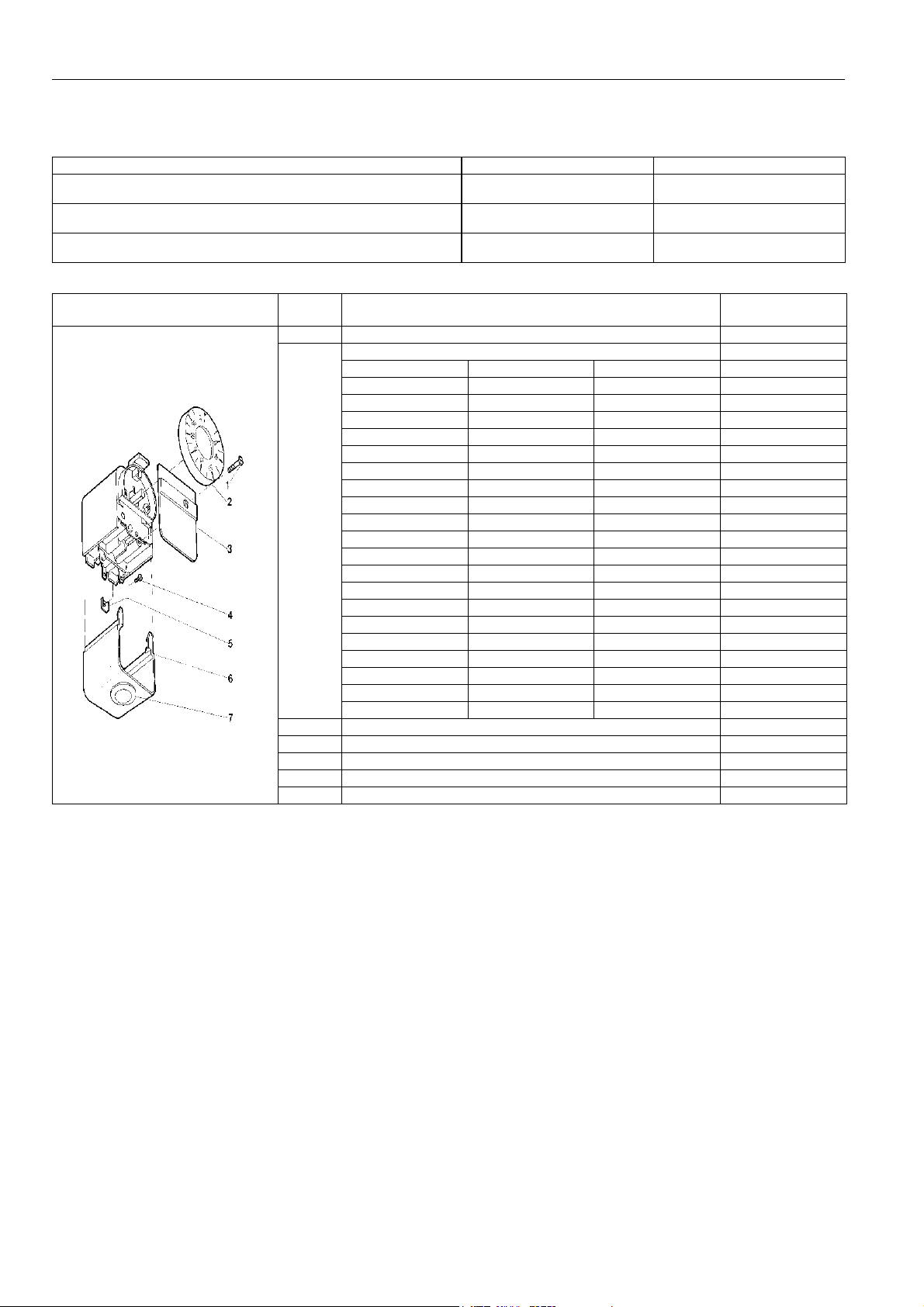
Miscellaneous
Description Ordernumber Packing qty (pcs)
Knob assembly
Scale range: 110 ... 230°F, high limit stop: 180°F
Knob assembly
Scale range: 40 ... 110°C, high limit stop: 82°C
Strap set for L6190 surface mounted aqustat
Strap length: 2000 mm
45.900.427-002 200
45.900.427-003 200
45.900.443-001 50
Key
number
1 Fixing screw for front covers of single and dual aquastats 45.002.700-001
2Knob
3 Cover for single Aquastat 45.002.547-002
4 Screw 45.000.219-015
5 Wire clamp 45.002.797-001
6 Conduit box 45.002.540-001
7 Push in plug 45.002.802-001
Description Part number
Scale range Low limit stop High limit stop
40 ... 110°C - - 45.002.823-001
70 ... 140°C - - 45.002.823-002
25 ... 95°C - - 45.002.823-003
40 ... 110°C- 95°C 45.002.823-004
70 ... 140°C95°C - 45.002.823-005
40 ... 110°C50°C95°C 45.002.823-006
25 ... 95°C- 82°C 45.002.823-007
40 ... 110°C- 100°C 45.002.823-008
25 ... 95°C- 60°C 45.002.823-010
70 ... 140°C- 95°C 45.002.823-011
25 ... 95°C60°C80°C 45.002.823-013
1 ... 7 (40 ... 110°C) - 85°C 45.002.823-014
50 ... 95°C- 82°C 45.002.823-015
40 ... 110°C- 82°C 45.002.823-017
25 ... 95°C40°C80°C 45.002.823-019
80 ... 100°F - - 45.004.213-001
110 ... 230°F - - 45.004.213-002
160 ... 280°F - - 45.004.213-003
110 ... 230°F- 200°F 45.004.213-004
110 ... 230°F- 180°F 45.004.213-005
19 EN2R-9005 0406R3-NE
Page 20

QUALITY ASSURANCE STATEMENT
Products are manufactured under an ISO 9001 (1994) based
and certified Quality System.
The quality system is described in the Honeywell Combustion
Controls Center Quality Assurance Programme and its related
operational procedures and instructions.
The quality system is approved by Gastec against certificate
number 9.302/2.
The quality organisation is responsible for defining,
maintaining, improving and verification of the quality systems
in the field of design, production process and field quality
service.
STANDARDS AND APPROVALS
Standards
The L41../L61.. series Aquastats have been designed
according the Low Voltage Directive 73/23/EEC.
This Low Voltage Directive is covered by approvals in
Denmark, Finland, Norway, Sweden and Switserland.
EMC Directive 89/336/EEC:
The snap action switch ensures in most cases a switching
action in less than 10 ms, which satisfies EMC-Directive
without further measures.
The exception is a highly inductive low current load combined
with slow rate of temperature change, which requires
additional suppression means. For this reason compliance
with the EMC-Directive cannot be claimed.
Europen countries accept above certificates as basis for
appliance approval.
Assembly processes are guided by work instructions. Patrol
inspections form part of the assembly processes.
At the end of the assembly phase, all aqustats are leakage
and performance tested/adjusted.
Assembly inspection is performed by employees of the quality
control department, using their own equipment.
All inspections (incoming and assembly) are performed by
trained personel and according inspection procedures.
Approvals
An additional approval is obtained from DIN in Germany
according to DIN 3440 as thermostat (TR) or temperature
limiter (TW).
In North-America approvals have been obtained from UL,
AGA and CSA.
EN2R-9005 0406R3-NE 20
Page 21
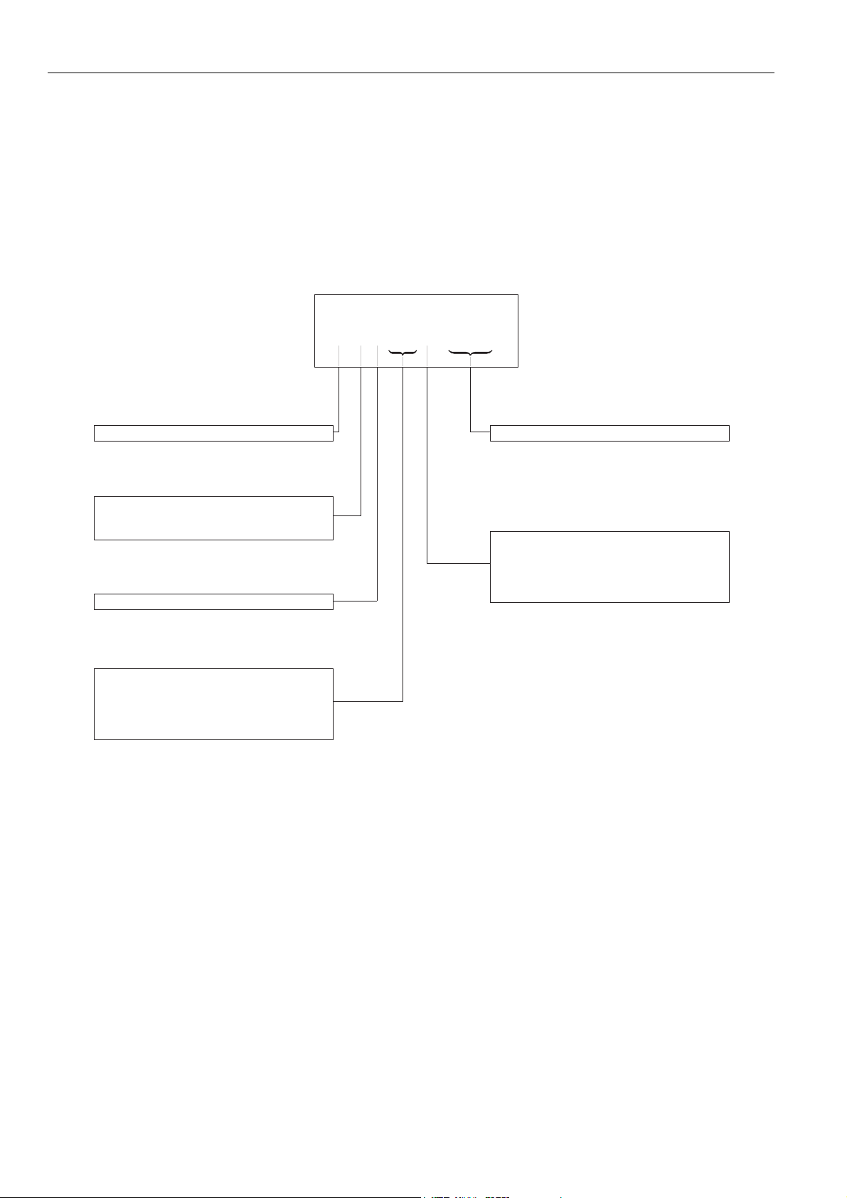
ORDERING INFORMATION
When ordering specify
• Setting point(control and limit if necessary)
• Type of contact (SPDT/SPST/ electrical rating)
• Number of sensing point (single/dual)
• Type of mounting (direct immersion/panel/surface)
• Differential (adjustable/fixed/manual reset)
• Capillary length
Ordering Specification number
L: Aquastat
Control contact:
4: SPST
6: SPDT
1: Family
88: Single aquastat, direct immersion
89: Single aquastat, panel mounting
90: Single aquastat, surface mounting
91: Dual aquastat, direct mounting
92: Triple aquastat, direct mounting
L
41X
X
A 9999
Specification number
A: Single: knob setting
Dual: automatic reset limiter
B: Single: internal setting (screw)
Dual: manual reset limiter
C: Single: manual reset
Fig. 11. Model number chart
21 EN2R-9005 0406R3-NE
Page 22

Home and Building Control
Combustion Control Center Europe
Honeywell BV
Phileas Foggstraat 7
7821 AJ Emmen
The Netherlands
Tel.: +31 (-)591 695911
Fax: +31 (-) 591 695200
http://europe.hbc.honeywell.com
EN2R-9005 0406R3-NE 22
 Loading...