

Honeyware VX6 User Manual

VX6
Vehicle-Mount Computer
Microsoft® Windows® CE 5 Operating System
User's Guide

Disclaimer
Honeywell International Inc. (“HII”) reserves the right to make changes in specifications and other information contained in this
document without prior notice, and the reader should in all cases consult HII to determine whether any such changes have
been made. The information in this publication does not represent a commitment on the part of HII.
HII shall not be liable for technical or editorial errors or omissions contained herein; nor for incidental or consequential damages
resulting from the furnishing, performance, or use of this material.
This document contains proprietary information that is protected by copyright. All rights are reserved. No part of this document
may be photocopied, reproduced, or translated into another language without the prior written consent of HII.
© 2004-2012 Honeywell International Inc. All rights reserved.
Web Address: www.honeywellaidc.com
RFTerm is a trademark or registered trademark of EMS Technologies, Inc. in the United States and/or other countries.
Microsoft®Windows, ActiveSync®, MSN, Outlook®, Windows Mobile®, the Windows logo, and Windows Media are
registered trademarks or trademarks of Microsoft Corporation.
Intel®and Intel XScale®are trademarks or registered trademarks of Intel Corporation or its subsidiaries in the United States
and other countries.
Summit Data Communications, the Laird Technologies Logo, the Summit logo, and "Connected. No Matter What" are
trademarks of Laird Technologies, Inc.
The Bluetooth®word mark and logos are owned by the Bluetooth SIG, Inc.
Symbol®is a registered trademark of Symbol Technologies. MOTOROLA, MOTO, MOTOROLA SOLUTIONS and the
Stylized M Logo are trademarks or registered trademarks of Motorola Trademark Holdings, LLC and are used under license.
Wavelink®, the Wavelink logo and tagline, Wavelink Studio™, Avalanche Management Console™, Mobile Manager™, and
Mobile Manager Enterprise™ are trademarks of Wavelink Corporation, Kirkland.
RAM®and RAM Mount™ are both trademarks of National Products Inc., 1205 S. Orr Street, Seattle, WA 98108.
Acrobat®Reader © 2012with express permission from Adobe Systems Incorporated.
Other product names or marks mentioned in this document may be trademarks or registered trademarks of other companies
and are the property of their respective owners.
Patents
For patent information, please refer to www.honeywellaidc.com/patents.
Limited Warranty
Refer to www.honeywellaidc.com/warranty_information for your product’s warranty information.

Table of Contents
Chapter 1: Introduction 1-1
About this Guide 1-1
Components 1-2
Top View 1-2
Front View 1-2
Bottom View 1-3
Back View 1-3
Control Panel 1-4
Access Panel 1-4
Chapter 2: Set Up A New VX6 2-1
Hardware Setup 2-1
Software Setup 2-1
End User License Agreement (EULA) 2-1
Backlights and Indicators 2-2
System Status LED 2-2
Keyboard LEDs 2-2
CAPS LED 2-2
Secondary Keys LED 2-2
Tapping the Touch Screen with a Stylus 2-3
Attach Stylus Tether and Sleeve 2-4
Using the Input Panel / Virtual Keyboard 2-5
Touch Screen 2-6
Calibrating the Touch Screen 2-6
Adjusting the Display Backlight Timer 2-6
Apply the Touch Screen Protective Film 2-6
Set Date and Time Zone 2-7
Grab Time Utility 2-7
Autolaunch Time-Sync 2-7
Synchronize with a Local Time Server 2-7
Adjust Speaker Volume 2-8
Using the Control Panel 2-8
Setup Terminal Emulation Parameters 2-9
Using the AppLock Switchpad 2-10
Using the Keypad 2-10
Using the Touch Screen 2-10
Connecting Bluetooth Devices 2-11
Taskbar Connection Indicator 2-11
Reboot 2-12
i

Warm Boot 2-12
Cold Boot 2-12
Connecting the Headset Cable 2-13
Adjust Headset / Microphone and Secure Cable 2-14
Cleaning the Touch Screen 2-15
Startup Help 2-16
Chapter 3: Connecting Cables to the VX6 3-1
Connect Cable - Serial 3-1
Connecting to USB and Optional Ethernet Ports 3-2
Connecting an AC/DC Power Supply 3-3
Connecting Vehicle Power 3-4
Vehicle 12-80VDC Power Connection Cable 3-4
Connect Vehicle 12-80VDC Connection 3-6
Connect VX6 without a UPS Battery Pack 3-7
Connect VX6 to an Integrated Mount UPS Battery Pack 3-8
Connect VX6 to a Remotely Mounted UPS Battery Pack 3-9
Power Adapter Cable 3-11
How To Connect Power Adapter Cable 3-11
Uninterruptible Power Supply Battery Pack 3-12
UPS Battery Pack Remote Mounting 3-12
UPS Battery Pack Remote Mounting Dimensions 3-13
Connecting a Tethered Scanner 3-14
Chapter 4: Product Agency Compliance - VX6 4-1
Lithium Battery Safety Statement 4-3
Vehicle Power Supply Connection Safety Statement 4-5
Chapter 5: Technical Assistance 5-1
ii
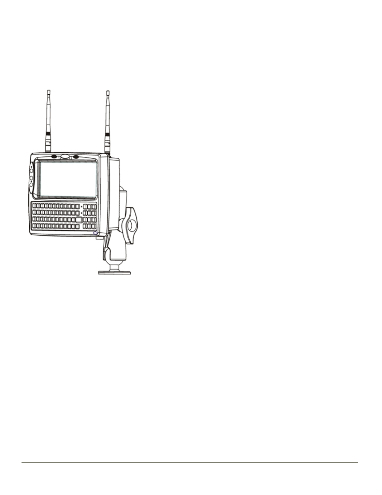
Chapter 1: Introduction
The VX6 Vehicle Mount Computer (VMC) is a rugged, vehicle mounted, PC
(Personal Computer) capable of wireless data communications from a fork-lift
truck or any properly configured vehicle.
The optional Bluetooth® module supports Bluetooth printers and scanners. The
VX6 provides the power and functionality of a desktop computer in a vehicle
mounted unit, with a wide range of options.
Contact Technical Assistance for information on the latest upgrades for your VX6.
About this Guide
This VX6 User's Guide provides instruction for the end-user or system administrator to follow when setting up a new VX6.
This user's guide has been developed for aVX6with a Microsoft® Windows® CE 5operating system.
1-1

Components
Top View
1. Access Panel Cover
2. Antenna Connectors or Hole Plugs
Front View
1. Speakers
2. Control Panel
3. 2nd Indicator
4. Caps Lock Indicator
1-2
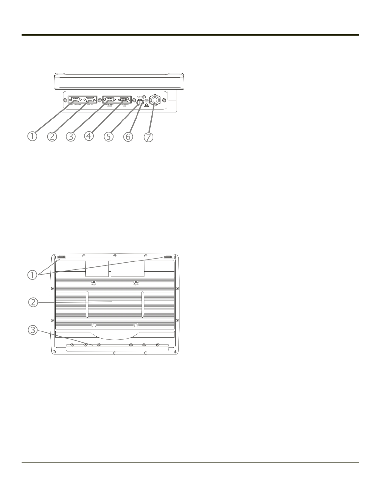
Bottom View
1. COM1/Scanner Connector
2. COM3 Connector
3. Keyboard/Mouse Connector (Not Used)
4. Ethernet/USB Cable Connector (USB-Host and USB-Client)
5. Fuse
6. Audio Connector
7. Power Cable Connector
Back View
1. Antenna Connectors
2. Bracket Mounting Area
3. Strain Relief Bracket and Screws
1-3
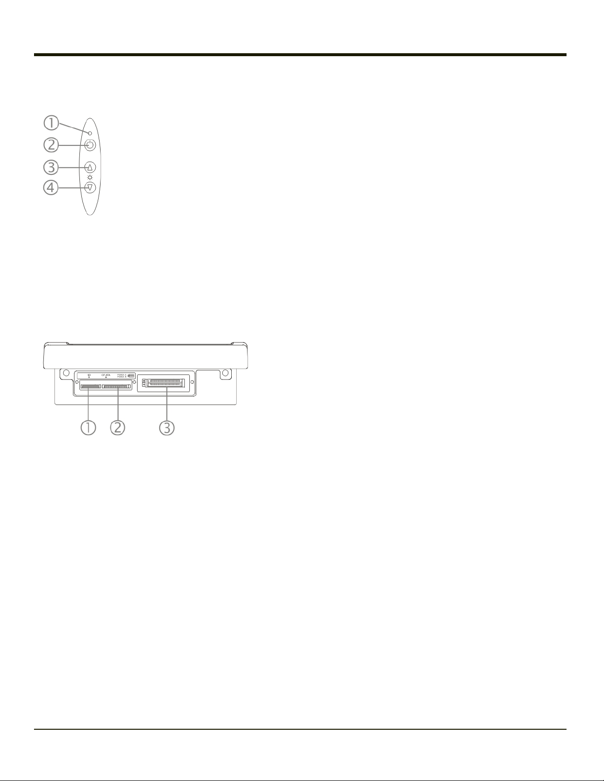
Control Panel
1. Status / Power LED
2. Power Switch
3. Brightness Increase
4. Brightness Decrease
Access Panel
Note: Access Panel cover not shown.
1. SD Memory Card Slot
2. Compact Flash Hard Drive
3. PCMCIA Slots
1-4

Chapter 2: Set Up A New VX6
This page lists a quick outline of the steps you might take when setting up a new VX6. More instruction for each step is listed
later in this guide. Please refer to the VX6Reference Guide for additional information and instruction.
Contact Technical Assistance if you need additional help.
Note: Installing or removing accessories should be performed on a clean, well-lit surface. When necessary, protect the work
surface, the VX6, and components from electrostatic discharge.
Hardware Setup
1. Connect accessories.
2. Connect cables.
3. Connect power cable.
4. Secure all cables to the VX6 with the Strain Relief Cable Clamps.
5. Press the Power key.
Software Setup
Prerequisite: Hardware setup is complete.
1. Calibrate Touch screen
2. Adjust Speaker Volume
3. Pair Bluetooth devices
4. Setup Wireless client parameters
5. Setup terminal emulation parameters
6. Save changed settings to the registry
7. Setup the AppLock parameters
8. Set the Scanner Wedge parameters
Please refer to the VX6Reference Guide for additional information and instruction.
End User License Agreement (EULA)
When a new VX6 starts up a EULA is displayed on the touch screen. It remains on the screen until the Accept or Decline
button is tapped with a stylus.
Tap the Accept button to accept the EULA terms and the VX6 continues the startup process. The EULA is not presented to the
user again.
Tap the Decline button to decline the EULA and the VX6 will reboot. It will continue to reboot until the Accept button is tapped
with the stylus.
Note: The EULA will be presented after any operating system upgrade or re-installation, including language-specific
operating systems.
2-1

Backlights and Indicators
System Status LED
The LED above the power button indicates the status of the VX6.
l Off - The VX6 is Off.
l Green - Running on 12V – 80V power input
l Solid Yellow - Running on UPS battery, battery is not low on power
l Flashing Yellow - Running on UPS battery, battery is critically low.
Keyboard LEDs
The VX6 has two keyboard LEDs located above the Enter key and between the alpha keypad and the numerical keypad.
CAPS LED
This LED indicates the state of the keyboard CapsLock mode. If CapsLock is enabled this LED is illuminated green. When
CapsLock is off, the LED is dark.
Press <2nd> then <F1> to toggle CapsLock On and Off. The default value of CapsLock is “Off”.
Secondary Keys LED
The keyboard is equipped with several secondary keys. These keys are identified by the superscripted text found on the
keyboard keys. The secondary keys are accessible by using two keystrokes: the <2nd> key followed by the superscripted
key.
Once the <2nd> state is enabled (by pressing the <2nd> key) the Secondary Mode LED is illuminated and the <2nd> state is
enabled until another key is pressed.
The <2nd> key is toggled on with a <2nd> keypress and then immediately off with another <2nd> keypress.
For example:
l Press <2nd> and <F1> to turn CapsLock on and off.
l Press <2nd> and <↑> to initiate the PgUp command.
l Press <2nd> and <Q> to type the “!” key.
l Press <2nd> and <BkSp> to enter the Insert (Ins) mode.
2-2

Tapping the Touch Screen with a Stylus
Note: Always use the point of the stylus for tapping or making strokes on the touch screen.
Never use an actual pen, pencil, or sharp/abrasive object to write on the touch screen.
Hold the stylus as if it were a pen or pencil. Touch an element on the screen with the tip of the stylus then remove the stylus
from the screen.
Firmly press the stylus into the stylus holder when the stylus is not in use.
Using a stylus is similar to moving the mouse pointer then left-clicking icons on a desktop computer screen.
Using the stylus to tap icons on the touch screen is the basic action that can:
l Open applications
l Choose menu commands
l Select options in dialog boxes or drop-down boxes
l Drag the slider in a scroll bar
l Select text by dragging the stylus across the text
l Place the cursor in a text box prior to typing in data
l Place the cursor in a text box prior to retrieving data using a scanner/imager or an input/output device connected to a
serial port.
A right-click can be simulated by touching the touch screen with the stylus and holding it for a short time.
A stylus replacement kit is available.
2-3

Attach Stylus Tether and Sleeve
The stylus kit includes the stylus, tether and sleeves. The tether allows the stylus to be mounted to the VX6 and the sleeve
provides storage for the stylus when not in use.
Determine a convenient location for the stylus sleeve.
Locate the most convenient tether mounting hole on the top of the VX6. Slide the clip end of the stylus tether into the tether
mounting hole.
Remove the paper backing from the stylus clip.
Apply the adhesive backed closed loop strip to the VX6 or mounting bracket. Press the hook strip on the elastic stylus sleeve
to the loop strip.
2-4
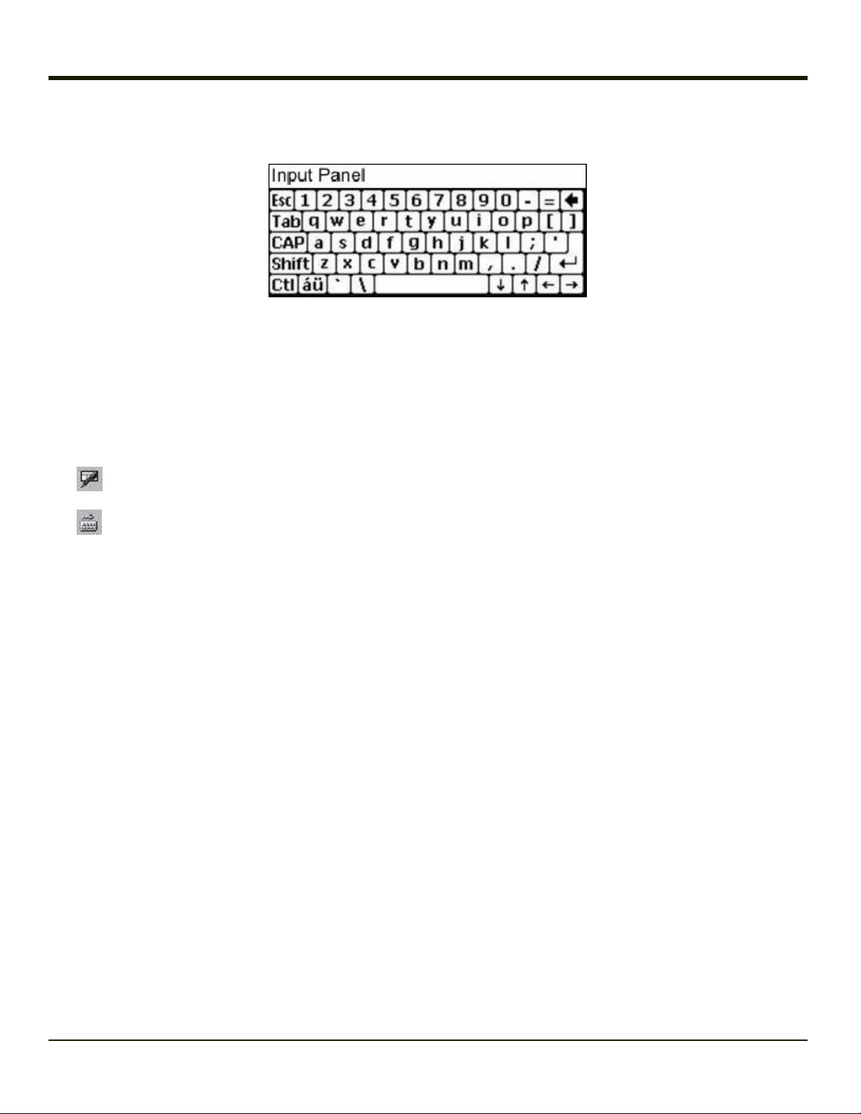
Using the Input Panel / Virtual Keyboard
The virtual keyboard is always available when needed e.g., text entry.
Place the cursor in the text entry field and, using the stylus:
l Tap the Shift key to type one capital letter.
l Tap the CAPS key to type all capital letters.
l Tap the áü key to access symbols.
Some applications do not automatically display the Input Panel. In this case, do the following to use the Input Panel:
Input Panel icon in the taskbar
Keyboard icon in the taskbar
l Tap the Input Panel or Keyboard icon in the taskbar.
l Select Keyboard from the menu.
l Move the cursor into the text entry field when you want to enter data using the Input Panel.
When finished entering data, tap the icon in the Taskbar again. Select Hide Input Panel.
2-5

Touch Screen
Calibrating the Touch Screen
If the touch screen is not responding properly to stylus taps, you may need to recalibrate the touch screen.
Recalibration involves tapping the center of a target. If you miss the center, keep the stylus on the screen, slide it over the
target's center, and then lift the stylus.
To recalibrate the screen, select Start > Settings > Control Panel > Stylus > Calibration tab.
To begin, tap the Recalibrate button on the screen with the stylus.
Follow the instructions on the screen and press the Enter key to save the new calibration settings or press Esc to cancel or
quit.
Adjusting the Display Backlight Timer
Start > Settings > Control Panel > Display > Backlight
The backlight settings use the Honeywell set of default timeouts and are synchronized to the User Idle setting in the Schemes
tab in the Power control panel.
When the backlight timer expires, the display backlight is dimmed, not turned off. When both checkboxes are unchecked, the
backlight never turns off (or dims).
Default values are 3 seconds for Battery, 2 minutes for External and both the check boxes are enabled.
Apply the Touch Screen Protective Film
First, clean the touch screen of fingerprints, lint particles, dust and smudges.
Remove the protective film from its container. Remove any protective backing from the film sheet by lifting the backing from a
corner of the film. Discard the backing.
1. Make sure both the touch screen and protective film are clean and dry before installation. Please review Cleaning the
Display for instructions on suitable cleaning agents.
2. Center the protective film over the touch screen. The antiglare side must be facing outward. Do not cut or trim the
protective film.
3. The protective film is approximately 1/10” (2.54cm) larger than the touch screen at the centers of the edges .
4. Slide the protective film so that one of the edges of the film can be slid between the touch screen and display housing
when the protective film is re-centered on the touch screen. Repeat for the other three edges, ensuring the protective
film is centered over the touch screen when finished.
5. To remove the protective film, slide the protective film in one direction until the edge clears. Lift up on the edge of the
film so it does not slide between the touch screen and display housing when slid back. Repeat until all edges are free
and remove the protective film.
Contact Technical Assistance about protective film packs designed specifically for your VX6 touch screen.
2-6

Set Date and Time Zone
Tap Start > Settings > Control Panel > Date/Time icon or tap the Date/Time in the taskbar.
Set Date, Time, Time Zone, and assign a Daylight Savings location on the VX6 after a warm boot or anytime.
There is very little functional change from standard desktop PC Date/Time Properties options. Adjust the settings and tap the
OK button or the Apply button to save changes to the registry. Any changes take effect immediately.
Double-tapping the time displayed in the Taskbar causes the Date/Time Properties screen to appear.
Grab Time Utility
The GrabTime utility can be configured to synchronize the time with a local server during each reboot function.
Tap the Sync button to synchronize date and time with a networked time server. By default, the VX6 operating system first
searches for a time server on the local intranet. If not found, it then searches the Internet for a time server. A connection to the
Internet is required for this option.
Autolaunch Time-Sync
Start > Settings > Control Panel > VX6 Options > Communication tab
By default, TimeSync does not automatically run on the VX6. To enable TimeSync to run automatically on the VX6 using the
GrabTime utility, check this checkbox.
Synchronize with a Local Time Server
By default, GrabTime synchronizes via an Internet connection. To synchronize with a local time server:
1. Use ActiveSync to copy GrabTime.ini from the My Device > Windows folder on the VX6 to the host PC.
2. Edit the copy of GrabTime.ini on the host PC. Add the local time server’s domain name to the beginning of the list of
servers. You can optionally delete the remainder of the list.
3. Copy the modified GrabTime.ini file to the My Device > System folder on the VX6. The System/GrabTime.ini file takes
precedence over the Windows/GrabTime.ini file. System/Grabtime.ini also persists after a coldboot;
Windows/Grabtime.ini does not persist.
2-7
 Loading...