

Honeytek HK68B, HK68C, HK68A User Manual
1
User’s Guide
Honeytek True RMS Auto Range Digital Multimeter
- HK68 Series
Shanghai HONEYTEK Electronic Instrument Co., Ltd (Headquarter)
1-2Fl., Building No.11A, Ruiqing Rd 528, Zhangjiang High-Tech Industrial Park,
Pudong District, Shanghai, China. (Zip Code: 201319)
Tel: 86-21-3807-3533 / Fax: 86-21-6818-2639
Shenzhen HONEYTEK Electronic Instrument Co., Ltd (Subsidiary)
3rd Fl., #4 Building, Yingrenshi Xiangxiang Industrial Park, Shiyan Town,
Bao’an District, Shenzhen, China (Zip Code: 518055)
Tel: 86-755-2951-9210 / Fax: 86-755-2662-1806
Email: info@honeytek.com
Website: www.honeytek.com

2
TABLE OF CONTENTS
1. INTRODUCTION
2. SAFETY
3. DESCRIPTION
3.1 Controls and Jacks
3.2 Front Panel Description
3.3 Symbols of LCD display
4. TECHNICAL SPECIFICATIONS
4.1 General Specifications
4.2 Measurement Specifications
5. OPERATING INSTRUCTIONS
5.1 AC and DC Voltage Measurement
5.2 Current Measurement
5.3 Diode Test and Continuity Check
5.4 Resistance Measurement
5.5 Capacitance Measurement
5.6 Temperature Measurement (for HK68B and HK68C)
5.7 Frequency (Duty Cycle) Measurement
5.8 Transistor hFE Test (for HK68A)
5.9 NCV (Non-Contact Voltage) Detection
5.10 LINE (Live Wire Recognition) Test
5.11 MAX/MIN
5.12 RELATIVE Mode
5.13 USB Interface (for HK68C)
5.14 Display Backlight
5.15 Hold Function
5.16 Auto Power Off
5.17 Low Battery Indication
6 MAINTENANCE
6.1 Battery Installation
6.2 Replacing the Fuses
3
1. INTRODUCTION
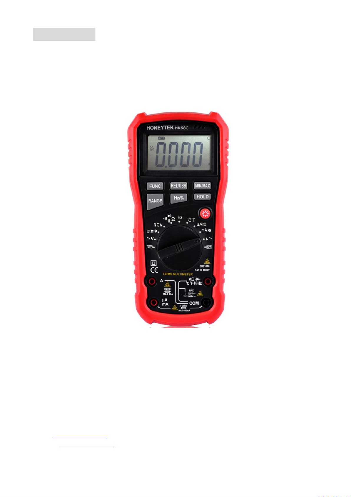
Congratulations on your purchase of the Honeytek HK68 series True RMS Auto range
multimeter. This range meters have been designed according to IEC-61010-2-032
concerning electronic measuring instruments with 1000V CAT III & CAT IV and pollution 2.
This range meters measures AC/DC Voltage, AC/DC Current, Resistance, Diode Test,
Continuity, Capacitance, Frequency, Transistor, Temperature, and Non-Contact Voltage
Detection. It features a rugged design for heavy duty use. Proper use and care of this meter
will provide many years of reliable service.
To fully utilize this meter, please keep this manual for reference carefully.
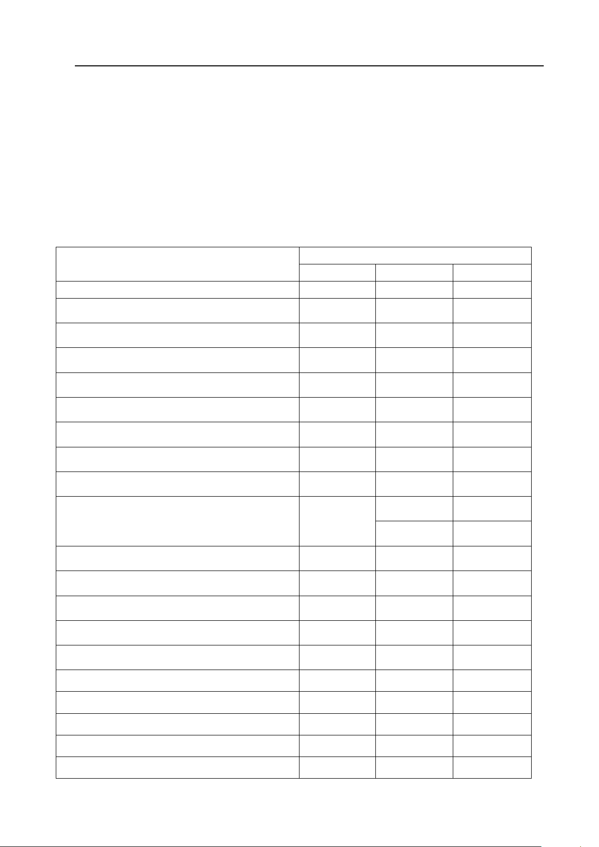
Function
Model No.
HK68A
HK68B
HK68C
Max. Display
4000 counts
4000 counts
6000 counts
Basic Accuracy
0.5%
0.5%
0.5%
DC Voltage Range
40mV-1000V
40mV-1000V
60mV-1000V
AC Voltage Range
40mV-750V
40mV-750V
60mV-750V
DC Current Range
400µA-10A
400µA-10A
600µA-10A
AC Current Range
400µA-10A
400µA-10A
600µA-10A
Resistance()
400-40M
400-40M
600-60M
Capacitance (CAP)
10nF-100mF
10nF-100mF
10nF-100mF
Frequency (Hz)
10Hz-10MHz
10Hz-10MHz
10Hz-10MHz
Temperature Test (℃/℉)
-
0℃-1000℃
0℃-1000℃
32℉-1832℉
32℉-1832℉
Transistor hFE Test
Yes - -
Diode Test
Yes
Yes
Yes
Continuity Check
Yes
Yes
Yes
Duty Cycle
Yes
Yes
Yes
NCV (Non-Contact Voltage) Detection
Yes
Yes
Yes
LINE (Live Wire Recognition) Test
Yes
Yes
Yes
Max. Input Protection
Yes
Yes
Yes
Relativity (Zero)
Yes
Yes
Yes
LCD Backlight
Yes
Yes
Yes
USB Interface
- - Yes
4
2. SAFETY
This symbol indicates that the operator must refer to an explanation in the Operating
Instruction to avoid personal injury or damage to the meter.
CAUTIONS:
● Improper use of this meter can cause damage, shock, injury or death. Read and
understand this user manual before operating the meter.
● Always remove the test leads before replacing the battery or fuses.
● Inspect the condition of the test leads and the meter itself for any damage before
operating the meter.
● Do not measure voltage if the voltage on the terminals exceeds 1000V above earth
ground.
● Use great care when making measurements if the voltages are greater 30VAC RMS or 60V
DC, these voltages are considered a shock hazard.
● Always discharge capacitors and remove power from the device under test before
performing Diode, Resistance or Continuity tests.
● To avoid damages to the meter, do not exceed the maximum limits of the input values
shown in the specification.
● In case the device is going to be unused for an extended period of time, remove the
batteries to prevent them from draining.
3. DESCRIPTION
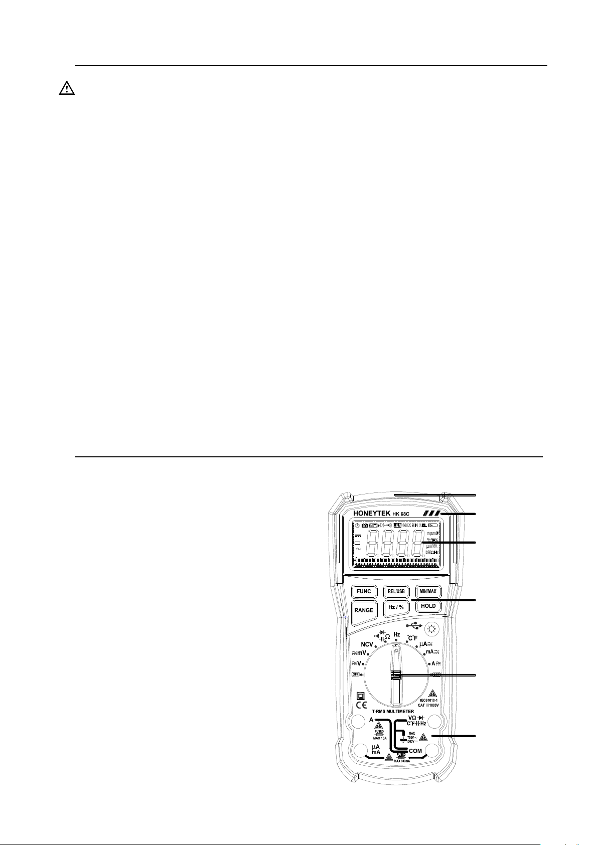
3.1 Controls and Jacks
1. Non-contact voltage detection position
2. LED indicator
3. LCD display
4. Function buttons
5. Rotary switch
6. Input jacks
Note: Tilt stand and battery compartment
are on rear of unit
USB
2、 L ED indic ator
3、 L CD display
4、 F unction b ut to ns
5、 R otary sw itch
6、 Inp ut j ac ks
1、 N on-co ntact volt age
d etection po sitio n
5
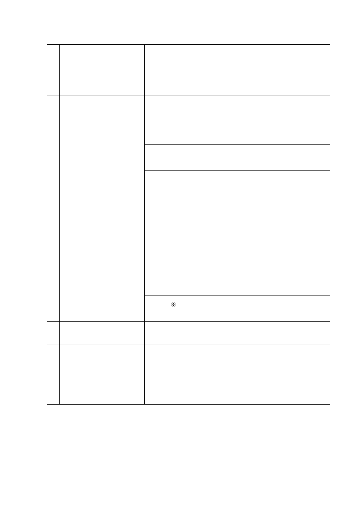
3.2 Front Panel Description
1
NCV Detection
(Non-Contact Voltage)
Move the rotary switch to NCV position, hold the meter
once detect the voltage, meter will be alarmed and LED
flash
2
LED Indicator
Once NCV alarm, LED indicator will flash, if detect
voltage increasing, the LED twinkles faster. NVC alarm
together with beeper sound.
3
LCD Display
The measured readings and symbols will be displayed in
this area.
4
Function Buttons
FUNC: the function select key that acts with trigger,
Use this key as switch to shift the measures of DC/AC,
Resistance/Continuity/Diode/ ℃/℉
REL: Press the "REL" key, you can measure the relative
value and ‘REL’ sign will appear on the LCD display in
the relative mode; Hold the button for 2 sec. to
activate USB communication with PC
MIN/MAX: Press this button LCD shows Max. value, Min.
value and difference value between max.& min.,
holding the button to exit this mode
RANGE: It is the auto/manual measurement push key,
the default is auto measurement once power is on, to
press one more time, will switch to manual
measurement. If press and hold this key over 2sec, the
meter will switch to auto measurement mode. You can
also manually choose the ranges once measures Voltage
& resistance.
Hz/%: the function shift button on frequency and duty
cycle measurement, valid under AC measuring modes.
HOLD: Press this button to lock the readings in the LCD,
press again to exit the hold mode.
Press " " to switch the back light mode, around 15sec.
exit from back light mode.
5
Rotary Switch
By moving the rotary switch to each individual range of
measurement or to the range needs to be measured
6
Input Jacks
V/Ω: the positive input terminal for voltage, resistance,
diode, temperature, frequency, capacitance, etc
COM: the negative input terminal for voltage, diode,
temperature, etc
mA: the input terminal for lower 600mA current
A: 10A input terminal
 Loading...