

Page 1

UDC 2300
Universal Digital Controller
Product Manual
51-52-25-73C
4/00
Sensing and Control
Page 2

Warranty/Remedy
Honeywell warrants goods of its manufacture as being free of defective materials and faulty workmanship.
Contact your local sales office for warranty information. If warranted goods are returned to Honeywell during
the period of coverage, Honeywell will repair or replace without charge those items it finds defective. The
foregoing is Buyer’s sole remedy and is in lieu of all other warranties, expressed or implied, including
those of merchantability and fitness for a particular purpose. Specifications may change without
notice. The information we supply is believed to be accurate and reliable as of this printing. However, we
assume no responsibility for its use.
While we provide application assistance personally, through our literature and the Honeywell web site, it is
up to the customer to determine the suitability of the product in the application.
Notices and Trademarks
Copyright 2000 by Honeywell
Release C April, 2000
Sensing and Control
Honeywell
11 West Spring Street
Freeport, IL 61032
UDC 2300 is a U.S. registered t rademark of Honeywell
Other brand or product names are trademarks of their respective owners.
ii UDC 2300 Controller Product Manual 4/00
Page 3

About This Document
Abstract
This document provides descriptions and procedures for the Installation, Configuration, Operation, and Troubleshooting of
your
UDC 2300 Controller.
Contacts
World Wide Web
The following lists Honeywell’s World Wide Web sites that will be of interest to our customers.
Honeywell Organization WWW Address (URL)
Corporate http://www.honeywell.com
Sensing and Control http://www.honeywell.com/sensing
International http://www.honeywell.com/Business/global.asp
Telephone
Contact us by telephone at the numbers listed below.
Organization Phone Number
United States and Canada Honeywell 1-800-423-9883 Tech. Support
1-888-423-9883 Q&A Faxback
(TACFACS)
1-800-525-7439 Service
Asia Pacific Honeywell Asia Pacific
Hong Kong
Europe Honeywell PACE, Brussels, Belgium [32-2] 728-2111
Latin America Honeywell, Sunrise, Florida U.S.A. (954) 845-2600
(852) 2829-8298
4/00 UDC 2300 Controller Product Manual iii
Page 4
Symbol Definitions
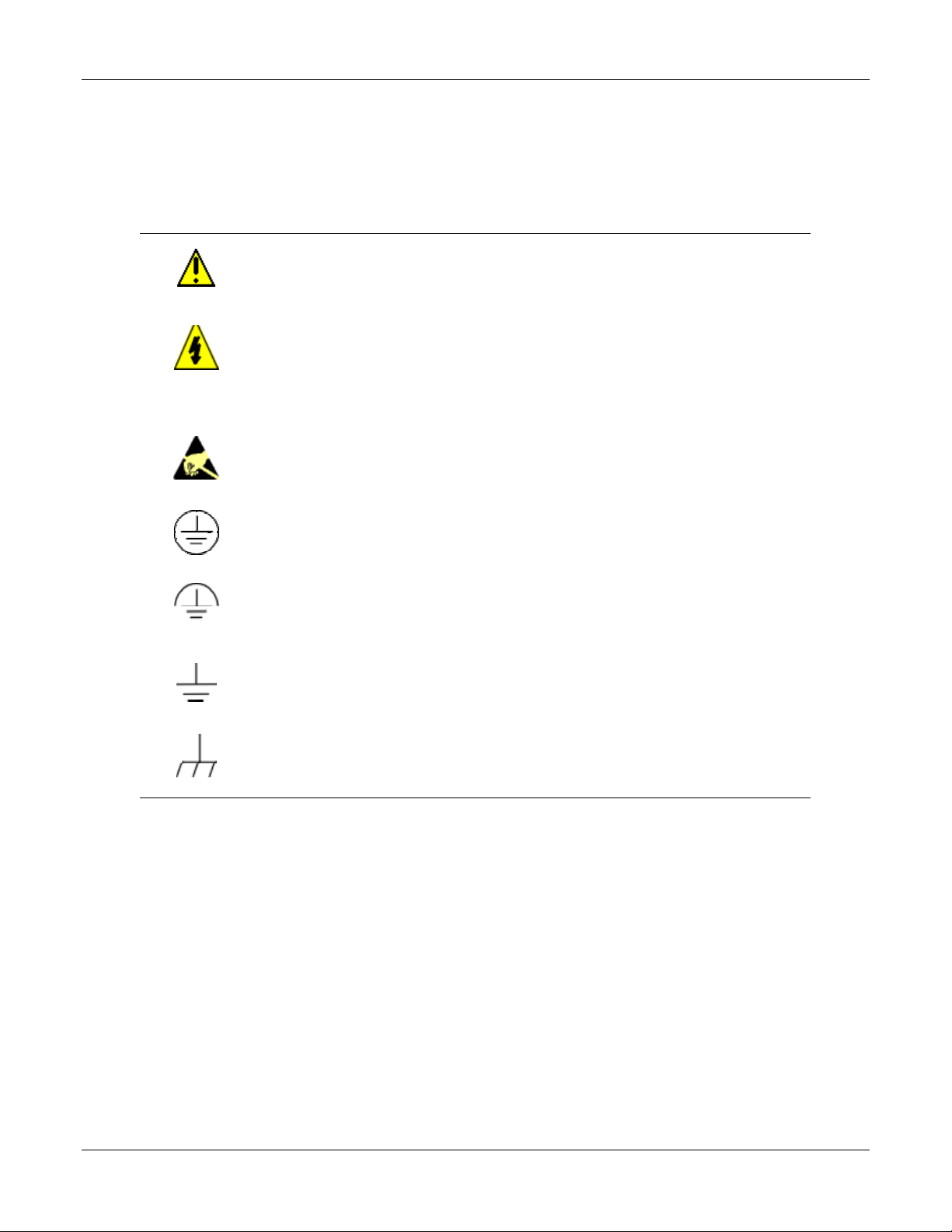
The following table lists those symbols used in this document to denote certain conditions.
Symbol Definition
This CAUTION symbol on the equipment refers the user to the Product Manual for
additional information. This symbol appears next to required information in the
manual.
WARNING
PERSONAL INJURY: Risk of electrical shock. This symbol warns the user of a
potential shock hazard where HAZARDOUS LIVE voltages greater than 30 Vrms,
42.4 Vpeak, or 60 VDC may be accessible. Failure to comply with these
instructions could result in death or serious injury.
ATTENTION, Electrostatic Discharge (ESD) hazards. Observe precautions for
handling electrostatic sensitive devices
Protective Earth (PE) terminal. Provided for connection of the protective earth (green
or green/yellow) supply system conductor.
Functional earth terminal. Used for non-safety purposes such as noise immunity
improvement. NOTE: This connection shall be bonded to protective earth at the
source of supply in accordance with national local electrical code requirements.
Earth Ground. Functional earth connection. NOTE: This connection shall be bonded
to Protective earth at the source of supply in accordance with national and local
electrical code requirements.
Chassis Ground. Identifies a connection to the chassis or frame of the equipment
shall be bonded to Protective Earth at the source of supply in accordance with
national and local electrical code requirements.
iv UDC 2300 Controller Product Manual 4/00
Page 5

Contents
1 INTRODUCTION...................................................................................................1
1.1 Overview........................................................................................................................................1
1.2 CE Conformity (Europe)................................................................................................................2
2 INSTALLATION.....................................................................................................3
2.1 Overview........................................................................................................................................3
2.2 Model Number Interpretation.........................................................................................................5
2.3 Preliminary Checks........................................................................................................................6
2.4 Control and Alarm Relay Contact Information.............................................................................. 8
2.5 Mounting........................................................................................................................................9
2.6 Wiring...........................................................................................................................................11
2.7 Wiring Diagrams.......................................................................................................................... 12
3 INITIAL START-UP.............................................................................................21
3.1 Overview......................................................................................................................................21
3.2 Powering Up the Controller .........................................................................................................21
3.3 Operator Interface and Key Functions.........................................................................................22
3.4 Key Error Message.......................................................................................................................22
4 CONFIGURATION .............................................................................................. 23
4.1 Overview......................................................................................................................................23
4.2 Configuration Prompt Hierarchy..................................................................................................24
4.3 Configuration Procedure..............................................................................................................25
4.4 Timer Set Up Group..................................................................................................................... 26
4.5 Tuning Set Up Group...................................................................................................................27
4.6 SP Ramp Set Up Group................................................................................................................29
4.7 Accutune Set Up Group ...............................................................................................................31
4.8 Algorithm Set Up Group..............................................................................................................32
4.9 Input 1 Set Up Group ...................................................................................................................33
4.10 Input 2 Set Up Group ...................................................................................................................35
4.11 Control Set Up Group...................................................................................................................36
4.12 Options Set Up Group..................................................................................................................38
4.13 Communications Set Up Group....................................................................................................39
4.14 Alarms Set Up Group................................................................................................................... 41
4.15 Configuration Record Sheet......................................................................................................... 43
4/00 UDC 2300 Controller Product Manual v
Page 6

5 MONITORING THE CONTROLLER ...................................................................45
5.1 Overview......................................................................................................................................45
5.2 Operator Interface.........................................................................................................................46
5.3 Entering a Security Code..............................................................................................................46
5.4 Lockout Feature............................................................................................................................47
5.5 Monitoring Your Controller......................................................................................................... 49
6 OPERATION ....................................................................................................... 53
6.1 Overview......................................................................................................................................53
6.2 Single Display Functionality........................................................................................................54
6.3 Start Up Procedure for Operation.................................................................................................56
6.4 Control Modes..............................................................................................................................57
6.4.1 Mode Definitions ..................................................................................................................57
6.4.2 What happens when you change modes................................................................................58
6.5 Setpoints.......................................................................................................................................58
6.6 Timer............................................................................................................................................59
6.7 Accutune II................................................................................................................................... 61
6.8 Fuzzy Overshoot Suppression...................................................................................................... 64
6.9 Using Two Sets of Tuning Constants...........................................................................................64
6.10 Alarm Setpoints............................................................................................................................66
6.11 Three Position Step Control Algorithm .......................................................................................67
6.12 Setting a Failsafe Output Value for Restart After a Power Loss.................................................68
6.13 Setting Failsafe Mode...................................................................................................................69
7 SETPOINT RATE/RAMP/PROGRAM OPERATION...........................................71
7.1 Overview......................................................................................................................................71
7.2 Setpoint Rate ................................................................................................................................72
7.3 Setpoint Ramp..............................................................................................................................72
7.4 Setpoint Ramp/Soak Programming..............................................................................................74
8 INPUT CALIBRATION ........................................................................................83
8.1 Overview......................................................................................................................................83
8.2 Minimum and Maximum Range Values ......................................................................................84
8.3 Preliminary Information...............................................................................................................85
8.4 Input 1 Set Up Wiring..................................................................................................................87
8.5 Input 1 Calibration Procedure......................................................................................................89
8.6 Input 2 Set Up Wiring..................................................................................................................91
8.7 Input 2 Calibration Procedure......................................................................................................92
8.8 Restore Factory Calibration .........................................................................................................93
vi UDC 2300 Controller Product Manual 4/00
Page 7

9 OUTPUT CALIBRATION .................................................................................... 95
9.1 Overview......................................................................................................................................95
9.2 Current Proportional Output Calibration ..................................................................................... 96
9.3 Auxiliary Output Calibration .......................................................................................................98
9.4 Three Position Step Output Calibration.....................................................................................100
10 TROUBLESHOOTING/SERVICE ..................................................................... 101
10.1 Overview....................................................................................................................................101
10.2 Troubleshooting Aids................................................................................................................. 102
10.3 Power-up Tests........................................................................................................................... 104
10.4 Status Tests................................................................................................................................. 104
10.5 Background Tests....................................................................................................................... 105
10.6 Controller Failure Symptoms..................................................................................................... 107
10.7 Troubleshooting Procedures.......................................................................................................108
11 PARTS LIST...................................................................................................... 115
11.1 Exploded View........................................................................................................................... 115
12 FUNCTION PARAMETER REFERENCE GUIDE ............................................. 117
12.1 Overview....................................................................................................................................117
12.2 Function Prompts .......................................................................................................................119
12.2.1 0 PCT (AUXILIARY OUTPUT LOW SCALING FACTOR) ...................................119
12.2.2 100 PCT (AUXILIARY OUTPUT HIGH SCALING FACTOR)...............................119
12.2.3 4-20 RG (CURRENT DUPLEX RANGE)..................................................................119
12.2.4 A TUNE (AUTOTUNE KEY LOCKOUT)................................................................120
12.2.5 ACTION (CONTROL OUTPUT DIRECTION) ........................................................ 120
12.2.6 ALARM1 (LATCHING ALARM FOR OUTPUT)....................................................120
12.2.7 ALHYST (ALARM HYSTERESIS)........................................................................... 121
12.2.8 AT ERR (ACCUTUNE ERROR CODES) ................................................................. 121
12.2.9 AUTOMA (AUTO/MANUAL KEY LOCKOUT).....................................................121
12.2.10 AUX OUT (AUXILIARY OUTPUT).........................................................................122
12.2.11 AxSxEV (ALARMx SETPOINTx EVENT - X = 1 OR 2).........................................123
12.2.12 AxSxHL (ALARMx SETPOINTx STATE - X = 1 OR 2) ......................................... 123
12.2.13 AxSxTY (ALARMx SETPOINTx TYPE - X = 1 OR 2)............................................124
12.2.14 AxSxVA (ALARMx SETPOINTx VALUE - X = 1 OR 2)........................................125
12.2.15 BAUD (BAUD RATE) ............................................................................................... 125
12.2.16 BIAS 1 (INPUT 1 BIAS).............................................................................................125
12.2.17 BIAS 2 (INPUT 2 BIAS).............................................................................................125
12.2.18 BLOCK (ALARM BLOCKING)................................................................................ 126
12.2.19 BRNOUT (BURNOUT PROTECTION - SENSOR BREAK)...................................126
12.2.20 ComADD (STATION ADDRESS).............................................................................127
12.2.21 ComSTA (COMMUNICATIONS STATE)................................................................127
12.2.22 CSP BI (COMPUTER SETPOINT BIAS)..................................................................127
12.2.23 CTRALG (CONTROL ALGORITHM)......................................................................127
4/00 UDC 2300 Controller Product Manual vii
Page 8

12.2.24 CSRATO (COMPUTER SETPOINT RATIO)........................................................... 129
12.2.25 CYC T1 or CT1 X3 (CYCLE TIME - HEAT)............................................................ 129
12.2.26 CYC2T2 or CT2 X3 (CYCLE TIME2 - COOL).........................................................130
12.2.27 DBAND (DEADBAND)............................................................................................. 130
12.2.28 DECMAL (DECIMAL POINT LOCATION).............................................................130
12.2.29 DI COM (DIGITAL INPUT COMBINATIONS)....................................................... 131
12.2.30 DIG IN (DIGITAL INPUT).........................................................................................131
12.2.31 DISPLAY (SINGLE DISPLAY DEFAULT)..............................................................133
12.2.32 EMISS (EMISSIVITY) ...............................................................................................133
12.2.33 ENDSEG (END SEGMENT)...................................................................................... 133
12.2.34 EUHRDN (RATE DOWN VALUE)...........................................................................133
12.2.35 EUHRUP (RATE UP VALUE) ..................................................................................133
12.2.36 FAILSF (FAILSAFE OUTPUT VALUE) ..................................................................134
12.2.37 FILTR1 (INPUT 1 FILTER).......................................................................................134
12.2.38 FILTR2 (INPUT 2 FILTER).......................................................................................134
12.2.39 FINLSP (SINGLE SETPOINT RAMP FINAL SETPOINT)......................................134
12.2.40 FREQ (POWER LINE FREQUENCY) ......................................................................135
12.2.41 FSMODE ( FAILSAFE MODE)................................................................................. 135
12.2.42 FUZZY (FUZZY OVERSHOOT SUPPRESSION)....................................................135
12.2.43 HYST (HYSTERESIS - OUTPUT RELAY ONLY).................................................. 135
12.2.44 I MIN or I RPM (RESET - INTEGRAL TIME) .........................................................136
12.2.45 I2 MIN or I2 RPM (RESET2 - INTEGRAL TIME) ...................................................136
12.2.46 INCRMT (TIME COUNT INCREMENT).................................................................136
12.2.47 IN1 HI (INPUT 1 HIGH RANGE VALUE)...............................................................137
12.2.48 IN1 LO (INPUT 1 LOW RANGE VALUE)...............................................................137
12.2.49 IN1TYP (INPUT 1 ACTUATION TYPE)..................................................................138
12.2.50 IN2 HI (INPUT 2 HIGH RANGE VALUE)...............................................................139
12.2.51 IN2 LO (INPUT 2 LOW RANGE VALUE)...............................................................139
12.2.52 IN2TYP (INPUT 2 ACTUATION TYPE)..................................................................140
12.2.53 L DISP (DISPLAY FOR TIMER OPTION)...............................................................140
12.2.54 LNGUAG (LANGUAGE)...........................................................................................140
12.2.55 LOCK (LOCKOUT) ...................................................................................................141
12.2.56 LOOPBACK (LOCAL LOOPBACK TEST).............................................................. 141
12.2.57 LSP’S (LOCAL SETPOINT SOURCE) .....................................................................141
12.2.58 MANRST (MANUAL RESET)..................................................................................142
12.2.59 MINRPM (RESET UNITS) ........................................................................................142
12.2.60 OUTALG (OUTPUT ALGORITHM) ........................................................................ 142
12.2.61 OUT Hi (HIGH OUTPUT LIMIT)..............................................................................143
12.2.62 OUT Lo (LOW OUTPUT LIMIT)..............................................................................143
12.2.63 PARITY (PARITY)..................................................................................................... 143
12.2.64 PB or GAIN (PROPORTIONAL BAND or GAIN)....................................................144
12.2.65 PB 2 or GAIN 2 (PROPORTIONAL BAND 2 or GAIN 2)........................................144
12.2.66 PBorGN (PROPORTIONAL BAND UNITS) ............................................................145
12.2.67 PERIOD (TIMEOUT PERIOD)..................................................................................145
12.2.68 PG END (PROGRAM TERMINATION STATE) ..................................................... 145
12.2.69 PIDSET (NUMBER OF TUNING PARAMETER SETS).........................................146
12.2.70 PVSTRT (PV START)................................................................................................147
12.2.71 PWROUT (THREE POSITION STEP CONTROL OUTPUT START-UP MODE).147
12.2.72 PWR UP (POWER UP CONTROLLER MODE RECALL)......................................148
12.2.73 RATE T (RATE TIME) .............................................................................................. 148
viii UDC 2300 Controller Product Manual 4/00
Page 9

12.2.74 RATE2T (RATE2 TIME) ........................................................................................... 148
12.2.75 RATIO1 (INPUT 1 RATIO) .......................................................................................149
12.2.76 RATIO2 (INPUT 2 RATIO) .......................................................................................149
12.2.77 RECYCL (RECYCLES) ............................................................................................. 149
12.2.78 RLY TY (RELAY CYCLE TIME INCREMENT).....................................................149
12.2.79 RESET (TIMER RESET CONTROL)........................................................................150
12.2.80 RN HLD (RUN/HOLD KEY LOCKOUT)................................................................. 150
12.2.81 RPUNIT (ENGINEERING UNITS FOR RAMP SEGMENTS) ................................150
12.2.82 RSPSRC (REMOTE SETPOINT SOURCE)..............................................................150
12.2.83 SECUR (SECURITY CODE) .....................................................................................151
12.2.84 SGx RP (SEGMENT RAMP - x = Segment Number 1 THROUGH 12)...................151
12.2.85 SGx SP (SEGMENT SETPOINT - x = Segment Number 1 THROUGH 12)............151
12.2.86 SGx TI (SEGMENT DURATION - x = Segment Number 1 THROUGH 12)...........152
12.2.87 SDMODE (SHED MODE) ......................................................................................... 152
12.2.88 SHD_SP (SHED SETPOINT RECALL) ....................................................................152
12.2.89 SHDTIM (SHED TIME)............................................................................................. 152
12.2.90 SOKDEV (GUARANTEED SOAK DEVIATION) ...................................................153
12.2.91 SP Hi (SETPOINT HIGH LIMIT)..............................................................................153
12.2.92 SP Lo (SETPOINT LOW LIMIT)...............................................................................153
12.2.93 SPPROG (SETPOINT RAMP/SOAK PROGRAM)..................................................154
12.2.94 SPRAMP (SINGLE SETPOINT RAMP) ................................................................... 154
12.2.95 SPRATE (SETPOINT RATE) ....................................................................................154
12.2.96 SP SEL (SETPOINT SELECT FUNCTION LOCKOUT) .........................................155
12.2.97 SP TRK (SETPOINT TRACKING)............................................................................155
12.2.98 START (TIMER START SELECTION)....................................................................155
12.2.99 STATE (PROGRAM STATE AT PROGRAM END)................................................155
12.2.100 STRSEG (START SEGMENT).................................................................................. 156
12.2.101 SW VAL (AUTOMATIC SWITCHOVER VALUE).................................................156
12.2.102 TI MIN (SINGLE SETPOINT RAMP TIME)............................................................156
12.2.103 TIMER (TIMER OPTION)........................................................................................156
12.2.104 ToBEGN (RESET PROGRAMMING TO BEGINNING) .........................................156
12.2.105 TUNE (ACCUTUNE - DEMAND TUNING)............................................................ 157
12.2.106 TX DLY (RESPONSE DELAY) ................................................................................157
12.2.107 UNITS (COMMUNICATION OVERRIDE UNITS).................................................157
12.2.108 UNITS (TEMPERATURE UNITS)............................................................................ 157
12.2.109 XMITR1 (TRANSMITTER CHARACTERIZATION) ............................................. 158
12.2.110 XMITR2 (TRANSMITTER CHARACTERIZATION) ............................................. 159
13 INDEX................................................................................................................ 161
4/00 UDC 2300 Controller Product Manual ix
Page 10

Tables
Table 2-1 Condensed Specifications _____________________________________________________4
Table 2-2 Preliminary Checks __________________________________________________________6
Table 2-3 Control Relay Contact Information ______________________________________________ 8
Table 2-4 Alarm Relay Contact Information _______________________________________________8
Table 2-5 Mounting Procedure_________________________________________________________10
Table 2-6 Permissible Wiring Bundling__________________________________________________12
Table 2-7 Universal Output Functionality and Restrictions___________________________________ 12
Table 4-1 Configuration Prompt Hierarchy _______________________________________________24
Table 4-2 Configuration Procedure _____________________________________________________ 25
Table 4-3 TIMER Group (Numeric Code 100) Function Prompts______________________________26
Table 4-4 TUNING Group (Numeric Code 200) Function Prompts ____________________________ 27
Table 4-5 SPRAMP Group (Numeric Code 300) Function Prompts ____________________________29
Table 4-6 ATUNE Group (Numeric Code 400) Function Prompts _____________________________ 31
Table 4-7 ALGOR Group (Numeric Code 500) Function Prompts _____________________________32
Table 4-8 INPUT1 Group (Numeric Code 600) Function Prompts_____________________________33
Table 4-9 INPUT2 Group (Numeric Code 700) Function Prompts_____________________________35
Table 4-10 CONTRL Group (Numeric Code 800) Function Prompts___________________________36
Table 4-11 Options Group (Numeric Code 900) Function Prompts ____________________________38
Table 4-12 Communications Group (Numeric Code 1000) ___________________________________ 39
Table 4-13 ALARMS Group (Numeric Code 1100) Function Prompts__________________________41
Table 5-1 Procedure to Enter a Security Code _____________________________________________47
Table 5-2 Annunciators ______________________________________________________________ 49
Table 5-3 Lower Display Key Parameter Prompts__________________________________________50
Table 5-4 Error Messages_____________________________________________________________51
Table 6-1 Single Display Parameters ____________________________________________________ 55
Table 6-2 Procedure for Starting Up the Controller_________________________________________ 56
Table 6-3 Control Mode Definitions ____________________________________________________57
Table 6-4 Changing Control Modes (Dual Display Only) ____________________________________58
Table 6-5 Procedure for Changing the Local Setpoints ______________________________________ 58
Table 6-6 Procedure for Switching Between Setpoints ______________________________________59
Table 6-7 Procedure for Starting “TUNE”________________________________________________61
Table 6-8 Procedure for Using TUNE at Start-up for Duplex Control __________________________62
Table 6-9 Procedure for Accessing Accutune Error Codes ___________________________________ 63
Table 6-10 Accutune Error Codes ______________________________________________________ 63
Table 6-11 Set Up Procedure __________________________________________________________ 65
Table 6-12 Procedure for Switching PID SETS from the Keyboard ____________________________ 65
Table 6-13 Procedure for Displaying Alarm Setpoints ______________________________________66
Table 6-14 Procedure for Displaying 3Pstep Motor Position__________________________________67
Table 6-15 Procedure for Setting a Failsafe Value__________________________________________68
Table 6-16 Procedure for Setting a Failsafe Mode__________________________________________69
Table 7-1 Running A Setpoint Ramp ____________________________________________________ 73
Table 7-2 Program Contents___________________________________________________________ 75
Table 7-3 Run/Monitor Functions ______________________________________________________80
Table 8-1 Voltage and Resistance Equivalents for Input 1 Range Values________________________84
Table 8-2 Equipment Needed__________________________________________________________86
Table 8-3 Set Up Wiring Procedure for Thermocouple Inputs Using an Ice Bath _________________87
Table 8-4 Set Up Wiring Procedure for Thermocouple Inputs using Thermocouple Source _________ 87
x UDC 2300 Controller Product Manual 4/00
Page 11

Table 8-5 Set Up Wiring Procedure for RTD Inputs ________________________________________ 88
Table 8-6 Set Up Wiring Procedure for Radiamatic, Milliampere, Millivolts, or Volts Inputs
(Except 0-10 Volts) ______________________________________________________________88
Table 8-7 Set Up Wiring Procedure for 0 to 10 Volts _______________________________________89
Table 8-8 Input 1 Calibration Procedure (Numeric Code 10000) ______________________________90
Table 8-9 Input 2 Calibration Procedure (Numeric Code 20000) ______________________________93
Table 8-10 Restore Factory Calibration __________________________________________________94
Table 9-1 Set Up Wiring Procedure for Current Proportional Output___________________________96
Table 9-2 Current Proportional Output Calibration Procedure (Numeric Code 30000)_____________ 97
Table 9-3 Set Up Wiring Procedure for Auxiliary Output____________________________________98
Table 9-4 Auxiliary Output Calibration Procedure (Numeric Code 50000) ______________________99
Table 9-5 3 Position Step Output Calibration Procedure (Numeric Code 40000)_________________100
Table 10-1 Procedure for Identifying the Software Version _________________________________103
Table 10-2 Procedure for Displaying the Status Test (Numeric Code 1200) Results ______________104
Table 10-3 Background Tests_________________________________________________________ 105
Table 10-4 Controller Failure Symptoms________________________________________________ 107
Table 10-5 Troubleshooting Power Failure Symptoms _____________________________________ 109
Table 10-6 Troubleshooting Current Proportional Output Failure_____________________________109
Table 10-7 Troubleshooting Time Proportional Output Failure ______________________________ 110
Table 10-8 Troubleshooting Current/Time or Time/Current Proportional Output Failure __________111
Table 10-9 Troubleshooting Alarm Relay Output Failure ___________________________________112
Table 10-10 Troubleshooting a Keyboard Failure _________________________________________ 113
Table 11-1 Parts Identification ________________________________________________________115
Table 11-2 Parts Not Shown__________________________________________________________116
Table 12-1 Function Parameter Look-up Table ___________________________________________118
4/00 UDC 2300 Controller Product Manual xi
Page 12

Figures
Figure 1-1 UDC 2300 Operator Interface__________________________________________________ 1
Figure 2-1 Model Number Interpretation __________________________________________________5
Figure 2-2 Jumper Placements __________________________________________________________7
Figure 2-3 Mounting Dimensions (not to scale)_____________________________________________ 9
Figure 2-4 Mounting Method __________________________________________________________10
Figure 2-5 Composite Wiring Diagram __________________________________________________ 13
Figure 2-6 Mains Power Supply________________________________________________________ 13
Figure 2-7 Input 1 Connections ________________________________________________________ 14
Figure 2-8 Input 2 Connections ________________________________________________________ 14
Figure 2-9 Electromechanical Relay Output_______________________________________________14
Figure 2-10 Solid State Relay Output____________________________________________________ 15
Figure 2-11 Open Collector Relay Output ________________________________________________15
Figure 2-12 Current Output ___________________________________________________________16
Figure 2-13 External Solid State Relay Option (Internal Open Collector Output) _________________16
Figure 2-14 Three Position Step Control Connections_______________________________________ 17
Figure 2-15 Alarm and Duplex Output Connections ________________________________________ 17
Figure 2-16 External Interface Option Connections_________________________________________18
Figure 2-17 Transmitter Power for 4-20 mA — 2 wire Transmitter Using Open Collector Alarm
2 Output (Model DC230B-XT-XX-XX-XXXXXXX-XX-X)______________________________ 19
Figure 2-18 Transmitter Power for 4-20 mA — 2 Wire Transmitter Using Auxiliary Output
(Model DC230B-XX-2X-XX-XXXXXXX-XX-X)______________________________________19
Figure 3-1 Operator Interface and Key Functions __________________________________________22
Figure 5-1 Operator Interface__________________________________________________________46
Figure 7-1 Ramp/Soak Profile Example__________________________________________________ 78
Figure 7-2 Program Record Sheet_______________________________________________________79
Figure 8-1 Input 1 and Input 2 Wiring Terminals___________________________________________85
Figure 8-2 Wiring Connections for Thermocouple Inputs Using an Ice Bath _____________________ 87
Figure 8-3 Wiring Connections for Thermocouple Inputs Using Thermocouple Source ____________87
Figure 8-4 Wiring Connections for RTD (Resistance Thermometer Device) _____________________ 88
Figure 8-5 Wiring Connections for Radiamatic, Milliampere, Millivolts, or Volts (Except 0 to 10
Volts) _________________________________________________________________________ 89
Figure 8-6 Wiring Connections for 0 to 10 Volts___________________________________________ 89
Figure 8-7 Wiring Connections for 4 to 20 mA Input – Input 2________________________________ 91
Figure 8-8 Wiring Connections for 1 to 5 Volt Input – Input 2 ________________________________92
Figure 9-1 Wiring Connections for Calibrating Current Proportional Output_____________________ 96
Figure 9-2 Wiring Connections for Calibrating Auxiliary Output______________________________98
Figure 11-1 UDC 2300 Exploded View _________________________________________________115
xii UDC 2300 Controller Product Manual 4/00
Page 13

1.1 Overview
The UDC 2300 is a microprocessor-based stand-alone controller. It combines reliability
and operating simplicity in a cost-effective 1/4-DIN size controller.
The UDC 2300 monitors and controls temperatures and other variables in applications
such as environmental chambers, plastic processing machines, furnaces and ovens, and
packaging machinery.
Its features include:
• Universal AC Power Supply,
• Input/Output Isolation,
• Isolated Auxiliary Current Output / Digital Input
• Modbus and ASCII Communications
Introduction
1 Introduction
• Timer
• Accutune II Tuning with Fuzzy Logic Overshoot Suppression.
• 2nd Input (Remote Setpoint)
• Setpoint Ramp/Rate/Program
• Three Position Step Control
• Duplex (Heat/Cool)
The UDC 2300 is also downward compatible with existing UDC 2000 applications and
installations except for RTD and 0-10 Volt inputs.
See wiring diagrams in Section 2 - Installation.
ALM
OUT
1
2
1
2
2300
PV
F
C
M
A
R
L
SP 2300
FUNCTION
DISPLAY
MAN-AUTO
RESET
SET UP
AUTO
TUNE
RUN
HOLD
Figure 1-1 UDC 2300 Operator Interface
4/00 UDC 2300 Controller Product Manual 1
Page 14

Introduction
1.2 CE Confor mi ty (Europe)
This product is in conformity with the protection requirements of the following European
Council Directives: 73/23/EEC, the Low Voltage Directive, and 89/336/EEC, the EMC
Directive. Conformity of this product with any other “CE Mark” Directive(s) shall not be
assumed.
Product Classification: Class I: Permanently connected, panel-mounted Industrial
Control Equipment with protective earthing (grounding). (EN61010-1).
Enclosure Rating: Panel-mounted equipment, IP 00. This controller must be panelmounted. Terminals must be enclosed within the panel. Front panel IP 65 (IEC 529).
Installation Category (Overvoltage Category): Category II: Energy-consuming
equipment supplied from the fixed installation, local level appliances, and Industrial
Control Equipment. (EN61010-1)
Pollution Degree: Pollution Degree 2: Normally non-conductive pollution with
occasional conductivity caused by condensation. (Ref. IEC 664-1)
EMC Classification: Group 1, Class A, ISM Equipment (EN55011, emissions), Industrial
Equipment (EN50082-2, immunity)
Method of EMC Assessment: Technical File (TF)
Declaration of Conformity: 51309602-000
Deviation from the installation conditions specified in this manual, and the special
conditions for CE conformity in Subsection 2.1, may invalidate this product’s conformity
with the Low Voltage and EMC Directives.
2 UDC 2300 Controller Product Manual 4/00
Page 15

2.1 Overview
Introduction
Installation of the UDC 2300 consists of mounting and wiring the controller according to
the instructions given in this section. Read the pre-installation information, check the
model number interpretation (Subsection 2.2), and become familiar with your model
selections, then proceed with installation.
What’s in this section?
The following topics are covered in this section.
2.1 Overview 3
Installation
2 Installation
TOPIC See Page
2.2 Model Number Interpretation 5
2.3 Preliminary Checks 6
2.4 Control and Alarm Relay Contact Information 8
2.5 Mounting 9
2.6 Wiring 11
2.7 Wiring Diagrams
Composite Wiring Diagram
AC Line Voltage
Input 1 Connections
Input 2 Connections
Relay Output
Electromechanical
Solid State
Open Collector
Current Output Connections
External Solid State Relay Output Option
Three Position Step Control Connections
Alarm and Duplex Output Connections
12
13
13
14
14
14
15
15
16
16
17
17
4/00 UDC 2300 Controller Product Manual 3
Page 16

Installation
Pre-installation Information
If the controller has not been removed from its shipping carton, inspect the carton for
damage then remove the controller.
• Inspect the unit for any obvious shipping damage and report any damage due to transit
to the carrier.
• Make sure a bag containing mounting hardware is included in the carton with the
controller.
• Check that the model number shown on the inside of the case agrees with what you
have ordered.
Condensed Specifications
Honeywell recommends that you review and adhere to the operating limits listed in Table
2-1 when you install your controller.
Table 2-1 Condensed Specifications
Operating Limits Ambient Temperature: 32 °F to 131 °F (0 °C to 55 °C)
Accuracy
CE Conformity Special
Conditions (Europe)
Relative Humidity: 5 % to 90 % RH up to 104 °F (40 °C)
Vibration:
Frequency: 0 to 200 Hz
Acceleration: 0.6g
Mechanical Shock:
Acceleration: 5g
Duration: 30 ms
Power:
90 Vac to 264 Vac, 50/60 Hz
(CSA models rated to 250 Vac maximum)
Power Consumption: 12 VA maximum
± 0.25 % of span typical
± 1 digit for display
15-bit resolution typical
Shielded twisted-pair cables are required for all analog I/O,
process variable, RTD, thermocouple, dc millivolt, low level
signal, 4-20 mA, digital I/O, and computer interface circuits.
Refer to 51-52-05-01, How to Apply Digital Instrumentation in
Severe Electrical Noise Environments, for additional
information.
4 UDC 2300 Controller Product Manual 4/00
Page 17
Installation
2.2 M odel Number Interpretation
Introduction
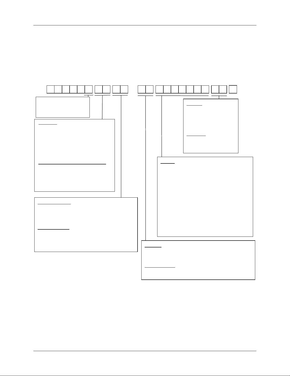
Write the model number into the spaces provided in Figure 2-1 and compare it to the model
number interpretation. This information will also be useful when you wire your controller.
DC230
B =
Basic Controller Model
L =
Limit Controller Model
Digital Indicator Model
I =
Output #1
0 _ =
None
C _ =
Current
E _ =
Relay, E-M
A _ =
Relay, SS 1 amp
S _ = Relay, SS 10 amp
T _ =
Open Collector Output
Output #2 or Ala r m #2 and Alarm #1
_ 0 =
No additional outputs or alarms
_ E =
Relay, E-M and Alarm #1
_ A =
Relay, SS 1 amp and Al ar m #
_ S =
Relay, SS 10 am p an d Alarm #1
_ T =
Open Collector Outp ut and Alarm #1
External Interface
0 _ =
None
1 _ =
RS422/485 ASCII / Modbus
2 _ =
Auxiliary Output or Digital Input
Software Options
_ 0 =
Single Display (includes Accutune II on DC230B)
_ A =
Dual Display, MA, + Accutune II
_ B =
Setpoint Programming (SPP), Dual Display,
MA, Accutune II
1
0
Manuals
0 _
= English
F _
= French (Europe)
G _
= German (Europe)
T _
= Italian (Europe)
S _ = Spanish (E urope)
Certificate
_ 0
= None
_ C = Certificate of
Conformance (F3391)
Options
0 _ _ _ _ _ _
1 _ _ _ _ _ _
_ 0 _ _ _ _ _
_ A _ _ _ _ _
_ _ 0 _ _ _ _
_ _ T _ _ _ _ = Customer ID Tag
_ _ _ 0 _ _ _
_ _ _ F _ _ _
_ _ _ _ 0 _ _
_ _ _ _ B _ _
_ _ _ _ T _ _
_ _ _ _ _ 0 _
_ _ _ _ _ _ 0
PV Input
1 _ = T/C, RTD,Radiamatic, mV, 0-5V, 0-20mA, 4-20mA
2_ = T/C, RTD,Radiamatic, mV, Volts,milliamps, 0-10 Volts
= 90 to 264 Vac Power
= 24 Vac/dc Power
(
requires Alarms plus IN 2)
= UL and CE
= UL, CE, CSA and (FM pending)
= None
= None
= Rear Terminal Cover
= Gray Elastomer Bezel
= Blue Elastomer Bezel
= Tan Elastomer Bezel
= Future
= Future
Optional Input 2
_ 0 = None
_ 1 = 0-5V, 1-5V, 0-20mA, 4-20mA
Figure 2-1 Model Number Interpretation
4/00 UDC 2300 Controller Product Manual 5
Page 18

Installation
2.3 Preliminary Checks
Introduction
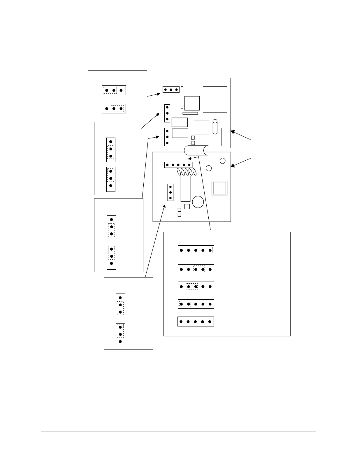
Before you install the controller, remove the chassis and make any preliminary checks
necessary that are listed in Table 2-2. Figure 2-2 shows the locations for jumper
placements.
Table 2-2 Preliminary Checks
Check
Number
1
2
3
4
Preliminary Check Description
Input I Jumper Placement
Optional Input 2 (RSP) Jumper
Placement
Control Relay 1 and Current
Output
Control Relay 2 and Alarm
Relay Action.
Check the internal jumper for INPUT 1 to make sure it
is set for the correct input type. The jumper is located at
position S101 on the printed wiring board. Figure 2-2
shows the location of the jumper and position
selections.
Check the internal jumper for INPUT 2 to make sure it
is set for the correct input type. The jumper is located at
position S201 on the printed wiring board. Figure 2-2
shows the location of the jumper and position
selections.
Check the internal jumper (W101) for CONTROL. The
relay is shipped as N.O. (Normally Open). Figure 2-2
shows the location of the jumper and position
selections.
See Table 2-3 for Control Relay contact information
The controller has been shipped with ALARM relays
configured for N.C. (Normally Closed). If you want to
change to N.O. refer to Figure 2-2, Jumper positions
W201 and W202:
W201 is the ALARM RELAY 1 jumper.
W202 is the jumper for CONTROL RELAY #2 for
Duplex Output or 3 position step control and an
ALARM RELAY 2 for all others.
See Table 2-3 for Control Relay contact information,
and Table 2-4 for Alarm Relay contact information.
See Alarm Relay Caution Note, Page 8.
Note: Solid State and Open Collector must have jumper set to N.O. (Normally Open).
3 Position Step and Time Duplex must have Output 2 jumper (W202) set to N.O.
6 UDC 2300 Controller Product Manual 4/00
Page 19
Jumper Placements
Installation
Input #2
2 1
S201
2
Alarm Relay #1
W201
NO
NC
NO
NC
Output #2/
Alarm Relay #2
W202
NO
NC
NO
Jumper
Position 2
Volt
Jumper
1
Position 1
mA
NC (default)
NO
NC (default)
NO
Note: Jumpers enlarged for clarity
2 1
S201
W201
NO
NC
W202
NO
NC
4 3 2
S101
NO
NC
W101
S101
1
Input #1
4 3 2
Main
Board
Position 1: thermocouple (default)
1
NC
Output #1
W101
NO
NC
NC
NO
NO (Default)
NC
1. For Current Output use the N.O. position
1
mA
Position 2: mV, Volt, RTD
Position 3: not used
Position 4:
No jumper: 0 -10 volts
Figure 2-2 Jumper Placements
4/00 UDC 2300 Controller Product Manual 7
Page 20
Installation
2.4 Control and Alarm Relay Contact Information
Control Relays
ATTENTION
Control relays operate in the standard control mode (that is, energized when output state is on).
Table 2-3 Control Relay Contact Information
Unit Power Control Relay
Alarm Relays
ATTENTION
Alarm relays are designed to operate in a failsafe mode (that is, de-energized during alarm sate).
This results in alarm actuation when power is OFF or when initially applied, until the unit
completes self diagnostics. If power is lost to the unit, the alarms will function.
Power
Off
On
Control Relay
Wiring
N.O. Open
N.C. Closed
N.O. Open
N.C. Closed
Contact
Closed
Open
Table 2-4 Alarm Relay Contact Information
Alarm Relay
Wiring
Variable NOT in Alarm State Variable in Alarm StateUnit
Relay
Contact
Indicators Relay
#1 or #2 Output
Indicator Status
Off
Off
On
Off
On
Indicators
Contact
Off
On
8 UDC 2300 Controller Product Manual 4/00
N.O. Open Open
N.C. Closed
N.O. Closed Open
N.C. Open
Off
Closed
Off
Closed
Off
On
Page 21
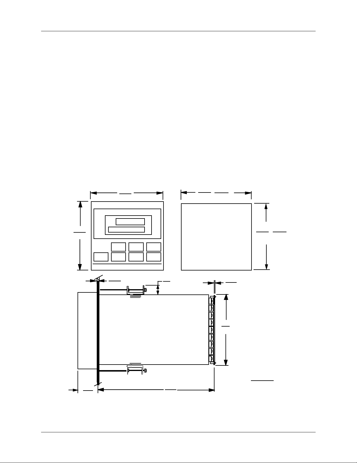
2.5 Mounting
Physical Considerations
The controller can be mounted on either a vertical or tilted panel using the mounting kit
supplied. Adequate access space must be available at the back of the panel for installation
and servicing activities.
• Overall dimensions and panel cutout requirements for mounting the controller are
shown in Figure 2-3.
• The controller’s mounting enclosure must be grounded according to CSA standard
C22.2 No. 0.4 or Factory Mutual Class No. 3820 paragraph 6.1.5.
• The front panel is moisture rated NEMA 3/IP65 (IEC) when properly installed with
panel gasket.
Overall Dimensions
96
3.780
92
90 =0.0
3.622 +0.031
3.5906
+0.8
+0.008
-0.0
+0.03
-0.0
Installation
96
3.780
21.0
.826
24
.945
Max Panel
Thickness
+0.008
92 -0.0
+0.031
Panel Cutout
10
.394
105.4
4.19
Max (2)
2.62
.103
90.7
3.57
3.622
with optional
rear cover
Dimensions:
Millimeters
Inches
-0.0
20751
Figure 2-3 Mounting Dimensions (not to scale)
4/00 UDC 2300 Controller Product Manual 9
Page 22
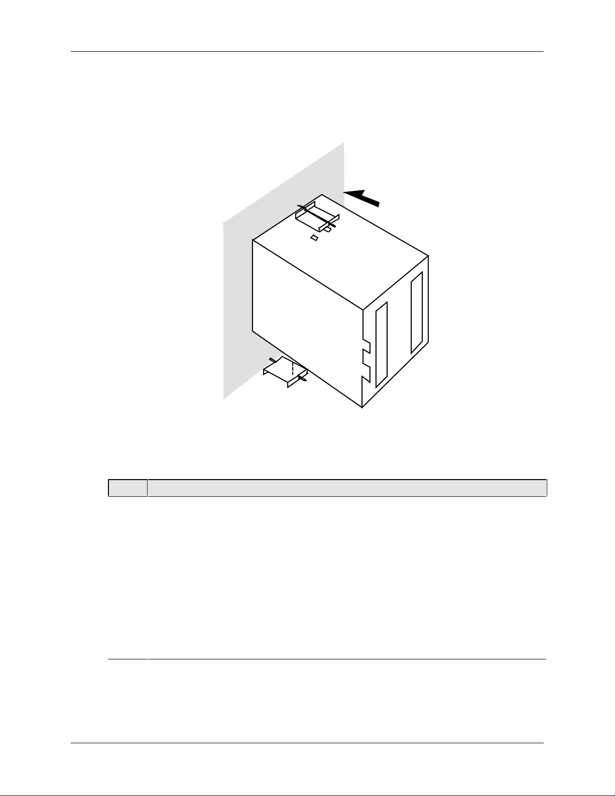
Installation
Mounting Method
Before mounting the controller, refer to the nameplate on the outside of the case and
make a note of the model number. It will help later when selecting the proper wiring
configuration.
Panel
Mounting Procedure
Step Action
Mark and cut out the controller hole in the panel according to the dimension information
1
in Figure 2-3.
Remove the screw cover and loosen the screw on the front of the controller. Pull the
2
chassis out of the case.
Orient the case properly and slide it through the panel hole from the front.
3
Remove the mounting kit from the shipping container and install the kit as follows:
4
• Install the screws into the threaded holes of the clips.
• Insert the prongs of the clips into the two holes in the top and bottom of the case.
• Tighten both screws to secure the case against the panel.
• Carefully slide the chassis assembly into the case, press to close, and tighten the
screw. Replace the screw cover.
20752
Figure 2-4 Mounting Method
Table 2-5 Mounting Procedure
10 UDC 2300 Controller Product Manual 4/00
Page 23

2.6 Wiring
Electrical Considerations
The controller is considered “rack and panel mounted equipment” per EN61010-1, Safety
Requirements for Electrical Equipment for Measurement, Control, and Laboratory Use, Part
1: General Requirements. Conformity with 72/23/EEC, the Low Voltage Directive requires
the user to provide adequate protection against a shock hazard. The user shall install this
controller in an enclosure that limits OPERATOR access to the rear terminals.
Mains Power Supply
This equipment is suitable for connection to 90 to 264 Vac, 50/60 Hz, power supply
mains. It is the user’s responsibility to provide a switch and non-time delay (North
America), quick-acting, high breaking capacity, Type F (Europe), 1/2A, 250V fuse(s), or
circuit-breaker, as part of the installation. The switch or circuit-breaker shall be located in
close proximity to the controller, within easy reach of the OPERATOR. The switch or
circuit-breaker shall be marked as the disconnecting device for the controller.
Controller Grounding
PROTECTIVE BONDING (grounding) of this controller and the enclosure in which it is
installed shall be in accordance with National and Local electrical codes. To minimize
electrical noise and transients that may adversely affect the system, supplementary
bonding of the controller enclosure to a local ground, using a No. 12 (4 mm
conductor, is recommended.
Installation
2
) copper
Control/Alarm Circuit Wiring
The insulation of wires connected to the Control/Alarm terminals shall be rated for the
highest voltage involved. Extra Low Voltage (ELV) wiring (input, current output, and
low voltage Control/Alarm circuits) shall be separated from HAZARDOUS LIVE (>30
Vac, 42.4 Vpeak, or 60 Vdc) wiring per Permissible Wiring Bundling, Table 2-6.
Electrical Noise Precautions
Electrical noise is composed of unabated electrical signals which produce undesirable
effects in measurements and control circuits.
Digital equipment is especially sensitive to the effects of electrical noise. Your controller
has built-in circuits to reduce the effect of electrical noise from various sources. If there is
a need to further reduce these effects:
• Separate External Wiring—Separate connecting wires into bundles
(See Permissible Wiring Bumdling - Table 2-6) and route the individual bundles
through separate conduit metal trays.
Use Suppression Devices—For additional noise protection, you may want to add
suppression devices at the external source. Appropriate suppression devices are
commercially available.
ATTENTION
For additional noise information, refer to document number 51-52-05-01, How to Apply Digital
Instrumentation in Severe Electrical Noise Environments.
4/00 UDC 2300 Controller Product Manual 11
Page 24
Installation
Permissible Wiring Bundling
Table 2-6 Permissible Wiring Bundling
Bundle No. Wire Functions
1
2Analog signal wire, such as:
3
• Line power wiring
• Earth ground wiring
• Control relay output wiring
• Line voltage alarm wiring
• Input signal wi re (thermocouple, 4 to 20 mA, etc.)
• 4-20 mA output signal wiring
Digital input signals
• Low voltage alarm relay output wiring
• Low voltage wiring to solid state type control circuits
2.7 Wiring Diagrams
Identify Your Wiring Requirements
To determine the appropriate diagrams for wiring your controller, refer to the model
number interpretation in this section. The model number of the controller can be found on
the outside of the case.
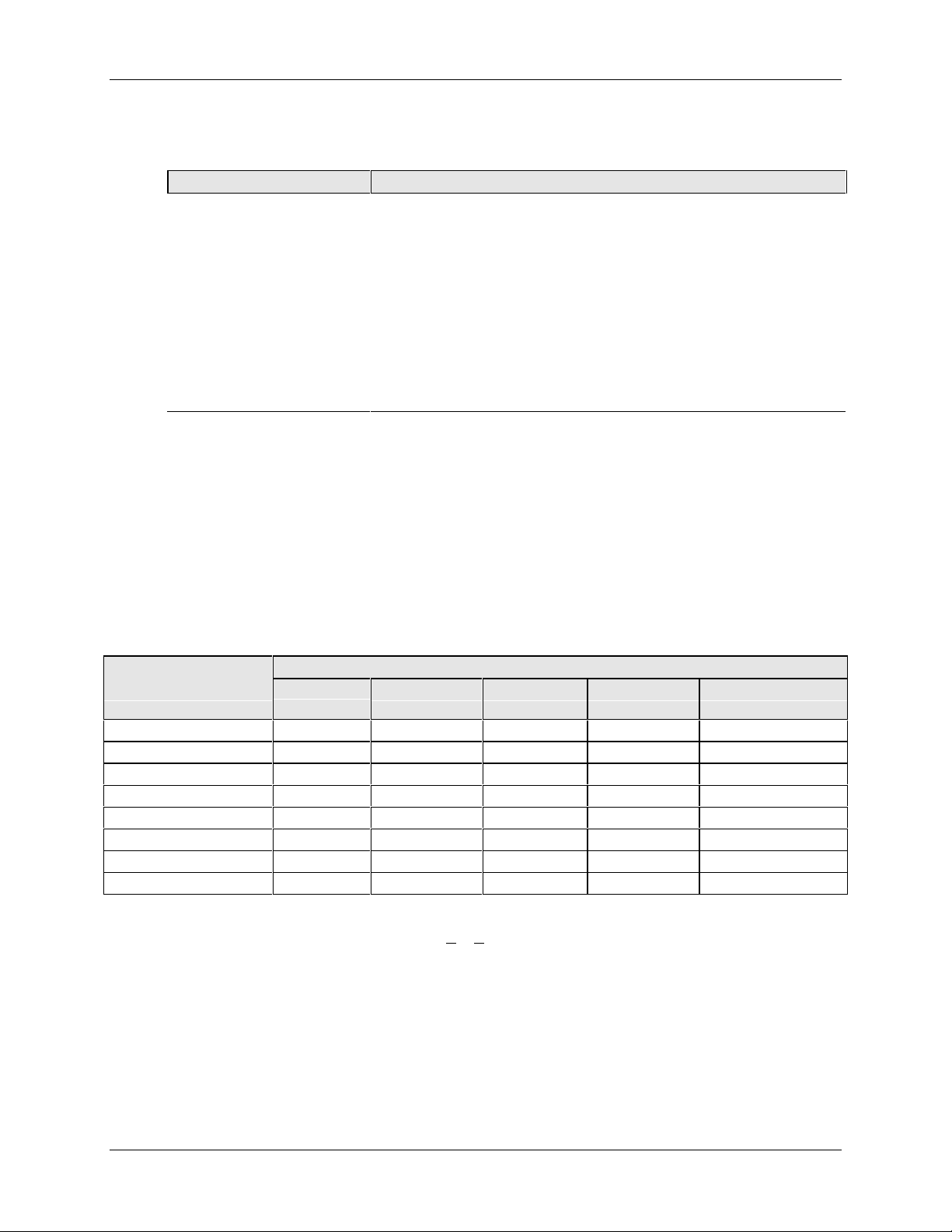
Universal Output Functionality and Restrictions
Table 2-7 Universal Output Functionality and Restrictions
Output/Socket
Output Type Current
Output
Time Simplex 1 N/I Output 1 Alarm 2 Alarm 1 Not Needed
Time Simplex 2 N/A N/I Output Alarm 1 Not Needed
Current Simplex Output N/I Alarm 2 Alarm 1 Not Needed
Time Duplex or TPSC N/I Output 1 Output 2 Alarm 1 Not Needed
Current Dup. 100 % Output 1 N/I Alarm 2 Alarm 1 Not Needed
Current Dup. 50 % Output 1 N/I Alarm 2 Alarm 1 Output 2
Current/Time Output 1 N/I Output 2 Alarm 1 Not Needed
Time/Current Output 2 N/I Output 1 Alarm 1 Not Needed
N/I = Not Installed
N/A = The output form or the individual output is Not A
Not Needed =Auxiliary Output is not needed to provide the desired output function and can be used for
another purpose. Auxiliary Output could also be used as a substitute for current Output 1.
Relay #1 Relay #2 Relay #3 Auxiliary Output
vailable or is not used for this output form.
12 UDC 2300 Controller Product Manual 4/00
Page 25
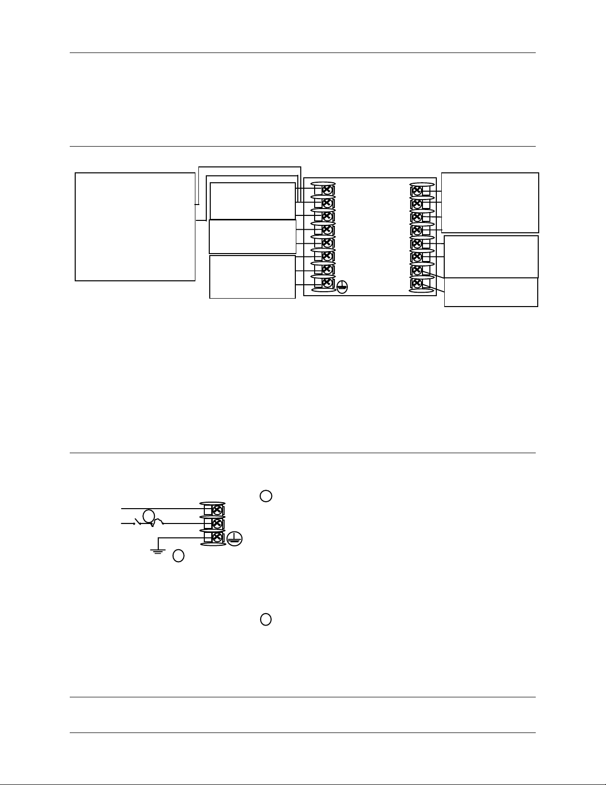
Wiring the Controller
Using the information contained in the model number, select the appropriate wiring
diagrams from the composite wiring diagram below. Refer to the individual diagrams
listed to wire the controller according to your requirements.
Installation
Transmitter Power for
4-20 mA 2-wire
transmitters
Using Alarm Output
•
See Figure 2-17
• Using Aux Output
See Figure 2-18
NOTE1:
Alarm and
Terminal
Input
See Figure 2-7
Control Output
Terminals
See Note 1
Mains Power
Supply Terminals
See Figure 2-6
8
7
6
5
4
L2 / N
L1
10
11
12
13
14
15
16
9
Duplex Output
Connections
See Figure 2-15
External Interface
Options Terminals
See Figure 2-16
Input #2 Terminals
See Figure 2-8
Time Proportional Electromechanical Relay Output – See Figure 2-9
Time Proportional Solid State Relay Output – See Figure 2-10
Time Proportional Open Collector Output – See Figure 2-11
Current Output – See Figure 2-12
External Solid State Relay Output – See Figure 2-13
Three Position Step Control Output – See Figure 2-14
Figure 2-5 Composite Wiring Diagram
24855
PROTECTIVE BONDING (grounding) of this controller
1
and the enclosure in which it is installed, shall be in
accordance with National and Local electrical codes. To
minimize electrical noise and transients that may
adversely affect the system, supplementary bonding of
the controller enclosure to a local ground, using a No.
2
12 (4 mm
) copper conductor, is recommended.
Mains
power
supply
2
Neutral
Hot
Ground
1
L2 / N
L1
24856
Before powering the controller, see “Preliminary
Checks” in this section of the Product manual for
switch and jumper settings.
Provide a switch and non-time delay (North America),
2
quick-acting, high breaking capacity, type F (Europe),
1/2 A, 250 V fuse(s), or circuit-breaker as part of the
installation.
Figure 2-6 Mains Power Supply
4/00 UDC 2300 Controller Product Manual 13
Page 26
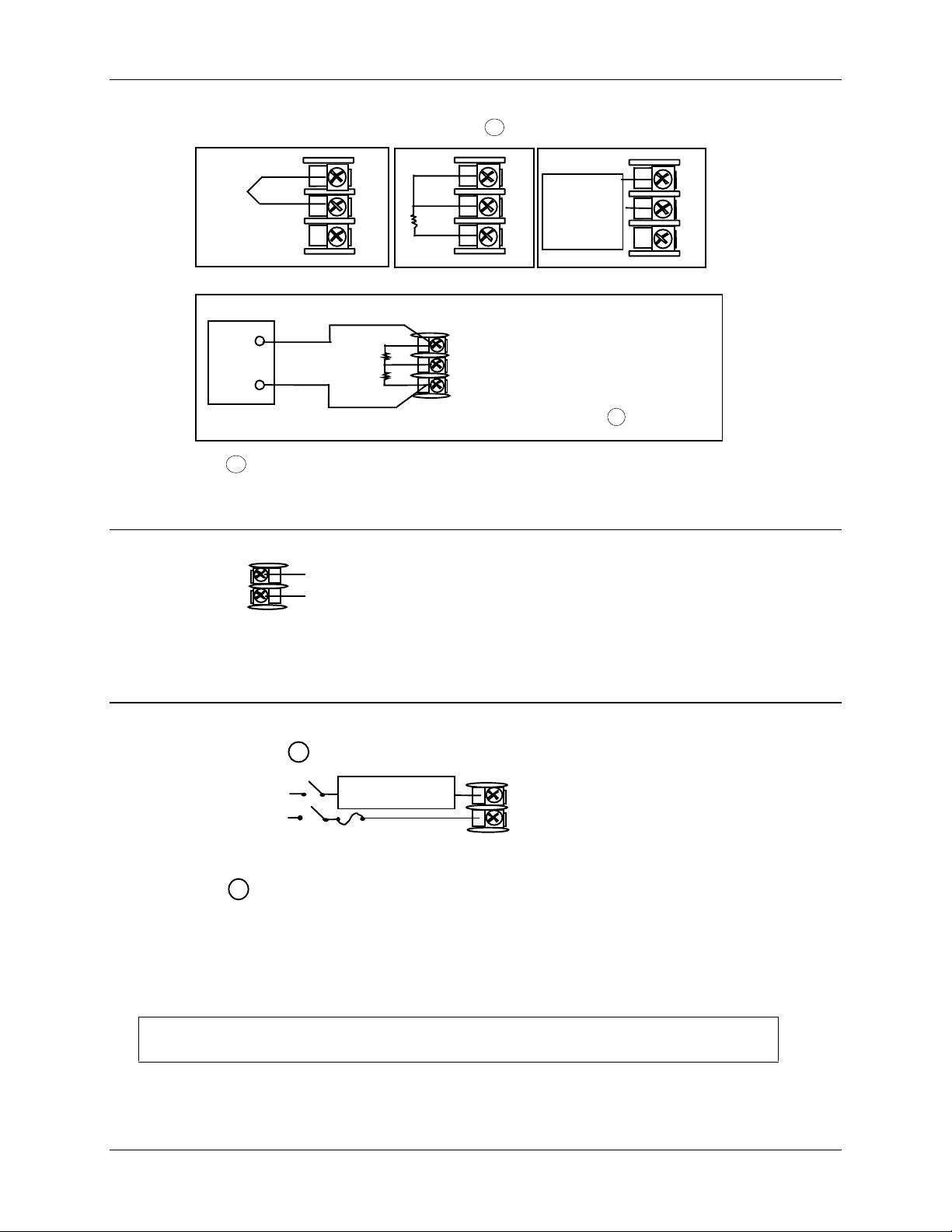
Installation
Volts is supplied with the
Thermocouple
Use
Thermocouple
extension wire
only
+
8
7
-
R
6
Platinum
RTD
RTD
1
8
+
7
-
R
6
0 to 10 Volts
The voltage divider for 0 to 10
+
_
controller when the input is
specified. You must install it
R
Volt
Source
+
_
1
2
3
8
7
6
when you wire the controller
before start-up. 1
1 These inputs are wired differently than the UDC2000
Figure 2-7 Input 1 Connections
+
15
16
0 to 20 mA,
_
4 to 20 mA,
0 to 5 Volts
1 to 5 Volts
24858
See “Preliminary Checks” in this
section of the Product Manual for
jumper selections.
mV, Volts (except 0-10V),
Milliamperes, or Radiamatic
+
mV, Volt,
or
Milliampere
Source
8
7
-
R
6
24857
Figure 2-8 Input 2 Connections
1
OUT1 OUT2/ALM2
Load
Supply
Power
Control relays 1 and 2 are configured N.O. as shipped. Alarm relays
1
Control Relay #1
Load
5 amp Fast Blo
5
4
9
10
24859
1 and 2 are configured N.C. as shipped. N.O. or N.C. configurations
are selectable by jumpers on the Main printed wiring boards.
See “Preliminary Checks” in this section of the
Product Manual for details.
Each SPST relay is rated at 5A, 120
Vac and 30 Vdc, 2.5 A 240 Vac. User-provided fuses should be sized
accordingly. For solid state relay outputs, see Figure 2-13.
See Figure 2-15 for Alarm and Duplex Output Connections.
See Table 2-3 and Table 2-4 for Control and Alarm Relay Contact information.
Figure 2-9 Electromechanical Relay Output
14 UDC 2300 Controller Product Manual 4/00
Page 27
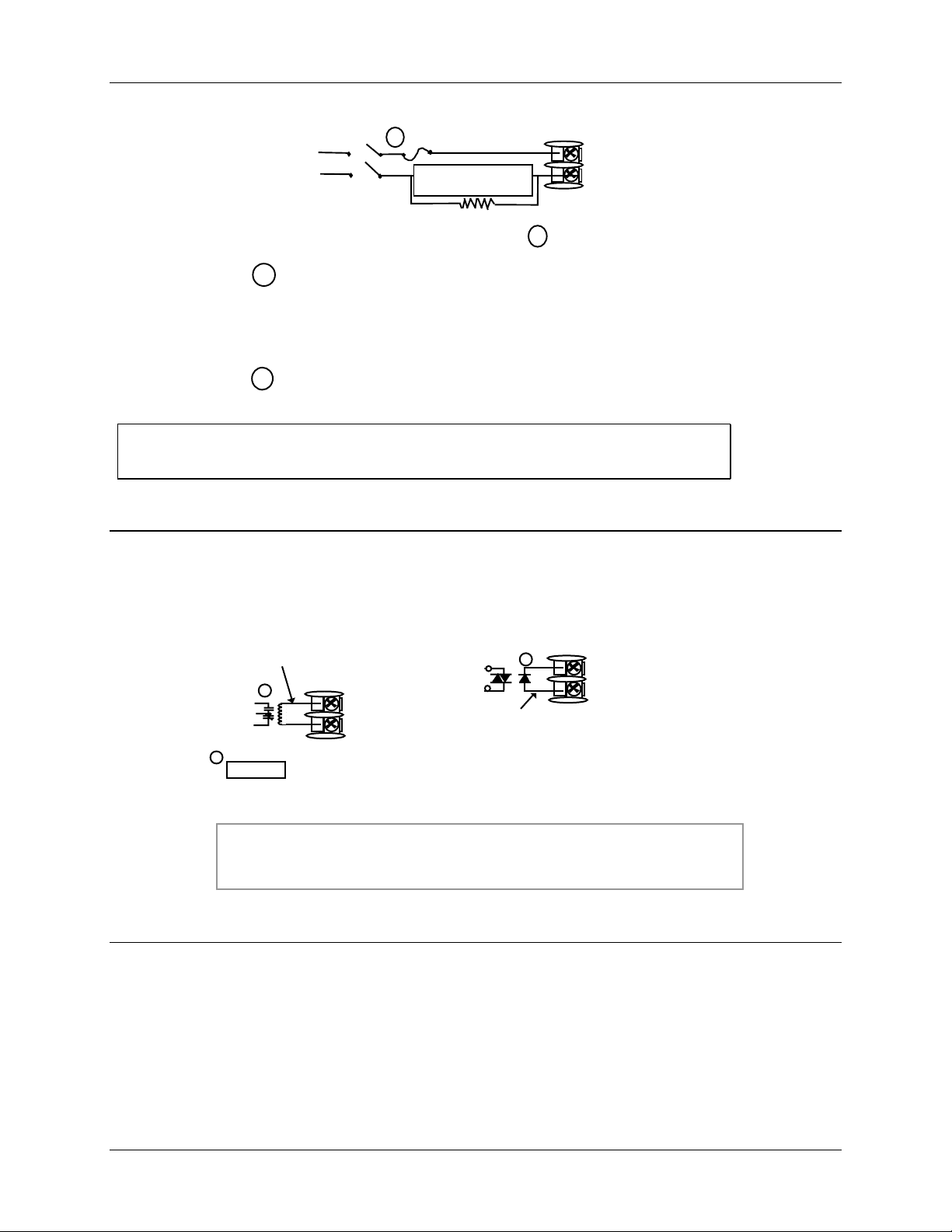
Installation
AC
2
Load
Power
Supply
1
If the load current is less than the minimum rated value of 20 mA,
1 amp Fast Blo
Control Relay #1
Load
Dummy Resistor
OUT1 OUT2/ALM2
5
4
1
9
10
24860
there may be a residual voltage across both ends of the load even
if the relay is turned off. Use a dummy resistor as shown to
counteract this. The total current through the resistor and the load
current must exceed 20 mA.
2
Solid State relay is rated at 1 Amp at 25°C, linearly derated to 0.5
Amp at 55°C. Customer should size fuse accordingly.
See Figure 2-15 for Alarm and Duplex Output Connections.
See Table 2-3 and Table 2-4 for Control and Alarm Relay Contact information.
Figure 2-10 Solid State Relay Output
Customer Supplied External
Electromechanical Relay
0-24 Vdc
OUT1 OUT2/ALM2
5–
4+
Open collector outputs are internally powered at 24 Vdc.
1
CAUTION
1
–
+
9 –
10+
Customer Supplied External
Solid State Relay
1
OUT1
–
+
OUT2/ALM2
5 –
4+
0-24 Vdc
9 –
10+
24861R
Connecting an external supply will damage the controller.
External relays should be fused between power and relay load.
See Figure 2-15 for Alarm and Duplex Output Connections.
See Tables 2-3 and 2-4 for Control and Alarm Relay Contact information
Figure 2-11 Open Collector Relay Output
.
4/00 UDC 2300 Controller Product Manual 15
Page 28
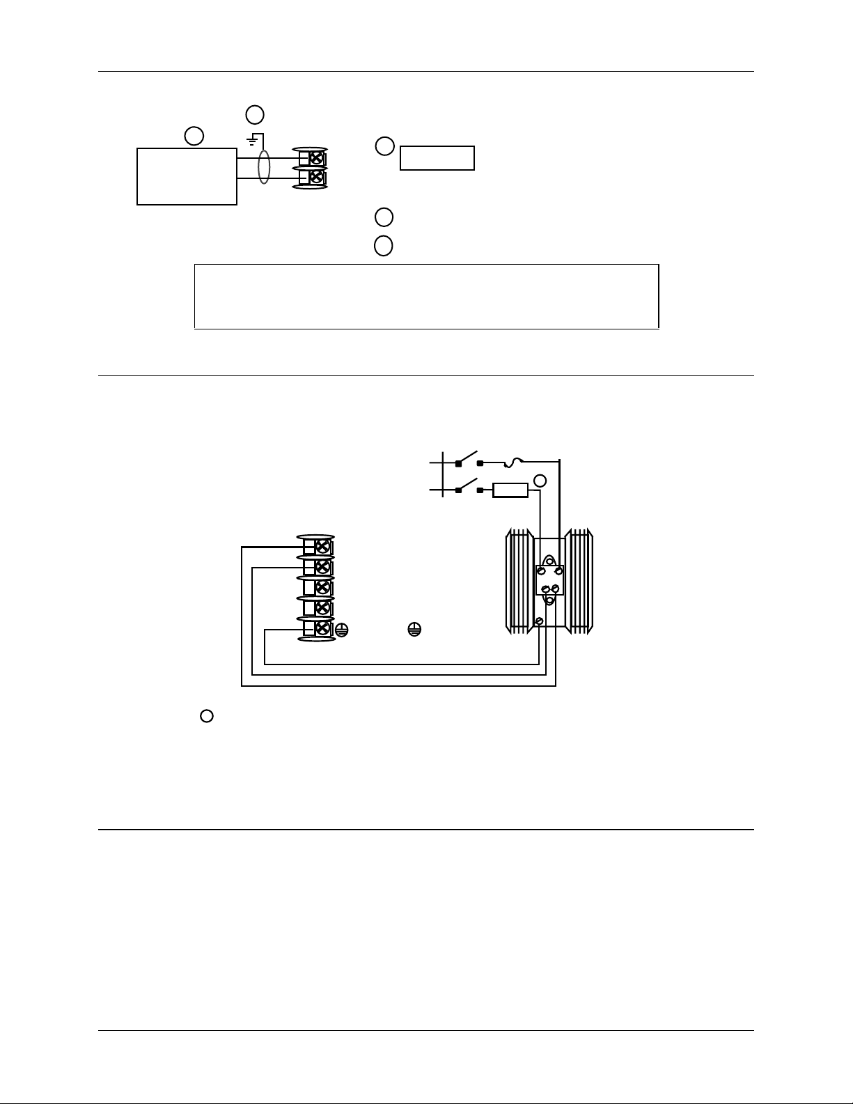
Installation
Controller
0 to 750 Ohms
24862
Load
2
1
+
-
5
4
Current
output
1
CAUTION
Installing a current output instrument
into a case wired for relay outputs
will damage the instrument.
2
Connect shield to ground at one end only.
4 to 20 mA
3
Set output jumper per Figure 2-2.
See Figure 2-15 for Alarm and Duplex Output Connections.
See Table 2-3 and Table 2-4 for Control and Alarm Relay Contact
information.
Figure 2-12 Current Output
10 amp Fast Blo
10 Amp Solid State
Relay Assembly
L1/H
L2/N
LOAD
1
White
Black
54+
L2 / N
Green
1
This Solid State relay is rated at 15 Amps at 25°C, linearly derated
to 10 Amps at 55°C.
Customer should size fuse accordingly
L1
9-
10+
L2 / N
L1
Green
Black
White
AC
-
+
Solid State
Relay
Assembly
24863R
Figure 2-13 External Solid State Relay Option (Internal Open Collector Output)
OUTPUT1 OUTPUT2
16 UDC 2300 Controller Product Manual 4/00
Page 29
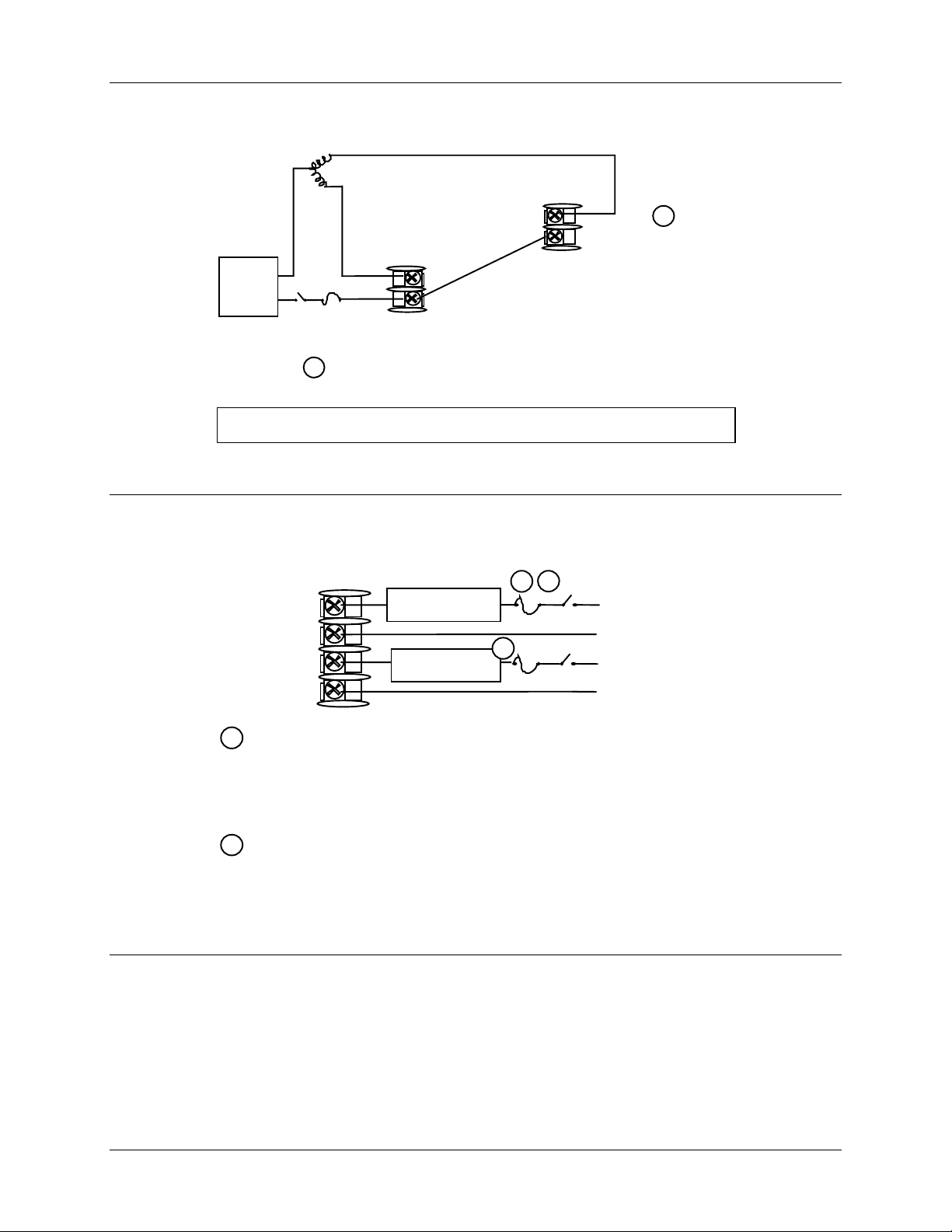
Close (CCW)
Installation
Open (CW)
9
Control Relay #2
10
Motor
Power
Supply
2 amp Fast Blo
1
Alarm #2 is not available with Three Position Step Control.
5+
4-
Control
Relay #1
See Figure 2-15 for Alarm and Duplex Output Connections.
Figure 2-14 Three Position Step Control Connections
1 2
10
11
12
9
Control or Alarm
Relay #2 Load
5 amp Fast Blo
Alarm
Relay #1 Load
1
5 amp fast Blo
Load
Supply
Power
Load
Supply
Power
1
24864
24867
1
Control relays 1 and 2 are configured N.O. as shipped. Alarm relays 1
and 2 are configured N.C. as shipped. N.O. or N.C. configurations are
selectable by jumpers on main printed wiring boards. See “Preliminary
Checks” in this sections of the Product Manual for details. Each SPST
relay is rated at 5 A, 120 Vac and 24 Vdc, 2.5 A, 240 Vac.
2
Alarm #2 not available for Time Proportional Duplex or Three Position
Step Control.
Figure 2-15 Alarm and Duplex Output Connections
4/00 UDC 2300 Controller Product Manual 17
Page 30
Installation
13
14
Auxiliary Output
+
_
Connect shield
to ground at one
end only.
1
Auxiliary
Load
0 - 500
Digital Inputs
+
13
Ω
14
_
1
Contact
Input
Switch
Connect shield
to ground at one
end only.
SHLD
1
D–
2
Communications
COMMUNICATION MASTER
(A) (RTN) (B)
D+
13
14
D+
D–
120 OHMS
1
1
TO OTHER
COMMUNICATION
CONTROLLERS
D+D–
120 OHMS ON LAST LEG
1
AuxOut , Digital Input and Communications are mutually exclusive.
Connect shield wires together with
supplied crimp part number 30755381-001
2
Do not run these lines in the same conduit
as AC power.
Figure 2-16 External Interface Option Connections
18 UDC 2300 Controller Product Manual 4/00
Page 31

2 Wire Transmitter
_
Installation
INPUT 1
8 +
7 -
OUTPUT 2
9 –
10+
Configure:
A2S1TYPE = NONE
A2S2TYPE = NONE
+
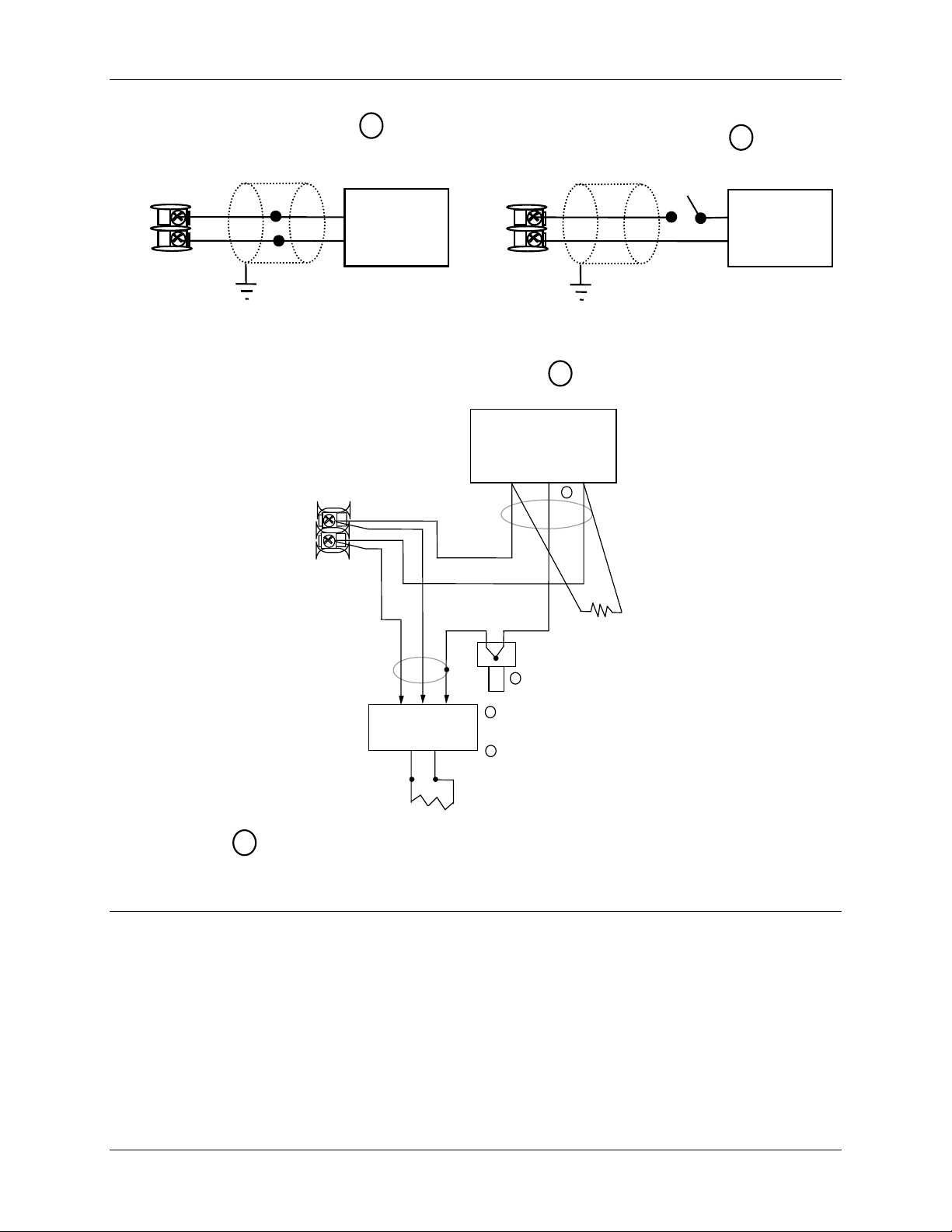
Figure 2-17 Transmitter Power for 4-20 mA — 2 wire Transmitter Using Open
Collector Alarm 2 Output
(Model DC230B-XT-XX-XX-XXXXXXX-XX-X)
2 Wire Transmitter
_
INPUT 1
8 +
7 -
AUXOUT
13 +
14 -
+
Configure:
AUXOUT = OUT
Auxiliary Output Calibration
ZEROVAL = 4095
SPANVAL = 4095
Figure 2-18 Transmitter Power for 4-20 mA — 2 Wire Transmitter
Using Auxiliary Output
(Model DC230B-XX-2X-XX-XXXXXXX-XX-X)
4/00 UDC 2300 Controller Product Manual 19
Page 32

Installation
20 UDC 2300 Controller Product Manual 4/00
Page 33

3 Initial Start-up
3.1 Overview
This section gives you the information necessary to start up your controller prior to
configuration. Review the Operator Interface portion to make sure you are familiar with
the indicator definitions and key functions.
3.2 Powering Up the Controller
Apply Power
When power is applied, the controller will run three diagnostic tests. After these tests are
completed, “TEST DONE” is displayed.
Test Failures
Initial Start-up
If one or more of these tests fail, the controller will go to the Failsafe Manual Mode, and
FAILSF will flash in the lower display and a message indicating which test failed will
appear in the lower display. Then, “DONE” will appear in the lower display.
4/00 UDC 2300 Controller Product Manual 21
Page 34

Initial Start-up
PV
RUN
Manual/Auto display
°Fahrenheit being use d
°Centigrade being used
- Remote or Local SP2
Lower Display
- Six alphanumeric characters
For default prompt of PV or Setpoint
and parameters
plus Timer start.
Decreases
or output value. Decreases the
mode groups.
Increases
or output value. Increases the
mode groups.
3.3 Oper ator Interface and Key Functions
FUNCTION
DISPLAY
MAN-AUTO
RESET
SET UP
ALM
- Alarm
conditions exist
OUT
- Control
Relay
1 or 2 on
Upper Display
• Normal operation - Process Variable
• Configuration mode - displays parameter
value or selection
TUNE-
•
ALM
1
2
1
OUT
2
- Four digits
Accutune in progress
2300
SP 2300
FUNCTION
DISPLAY
Keys
AUTO
TUNE
Selects functions within each configurati on group.
Selects 2nd Setpoint or Remote Setpoint.
Returns Controller to normal display from Set Up
mode.
Toggles various operating parameters for display.
Selects Manual or Auto mode.
Resets the latching Limit Controller relay.
In Set Up mode, used to restore original value or
selection.
Scrolls through the configuration Setup groups.
MAN-AUTO
RESET
F
C
M
A
R
L
SET UP
HOLD
AUTO
TUNE
RUN
HOLD
F
-
C
-
Mor A R
L
- Local setpoint active
• Normal operation – display is blank unless configured
• Configuration mode - displays func tions
24868
setpoint active
Initiates Limit Cycle Tuning (Accutune).
setpoint
configuration values or changes functions in Configurat i on
setpoint
configuration values or changes functions in Configurat i on
Enables Run/Hold of the SP Ramp or Program
Figure 3-1 Operator Interface and Key Functions
3.4 Key Error Message
When a key is pressed and the prompt KEYERR appears in the lower display, it will be
for one of the following reasons:
• parameter is not available,
• not in Set Up mode, press SET UP key first,
• key malfunction.
22 UDC 2300 Controller Product Manual 4/00
Page 35

4.1 Overview
Introduction
Configuration is a dedicated operation where you use straightforward keystroke
sequences to select and establish (configure) pertinent control data best suited for your
application.
To assist you in the configuration process, there are prompts that appear in the upper and
lower displays. These prompts let you know what group of configuration data (Set Up
prompts) you are working with and also, the specific parameters (Function prompts)
associated with each group.
Figure 3-1 shows you an overview of the prompt hierarchy as they appear in the
controller.
Configuration
4 Configuration
As you will see, the configuration data is divided into 11 main Set Up groups plus
prompts for calibration and prompts that show the status of the continuous background
tests that are being performed.
What’s in this section?
The following topics are covered in this section.
4.1 Overview 23
4.2 Configuration Prompt Hierarchy 24
4.3 Configuration Procedure 25
4.4 Timer Set Up Group 26
4.5 Tuning Set Up Group 27
4.6 SP Ramp Set Up Group 29
4.7 Accutune Set Up Group 31
4.8 Algorithm Set Up Group 32
4.9 Input 1 Set Up Group 33
4.10 Input 2 Set Up Group 35
TOPIC See Page
4.11 Control Set Up Group 36
4.12 Options Set Up Group 38
4.13 Communications Set Up Group 39
4.14 Alarms Set Up Group 41
4.15 Configuration Record Sheet 43
4/00 UDC 2300 Controller Product Manual 23
Page 36

Configuration
4.2 Confi guration Prompt Hierarchy
Table 4-1 Configuration Prompt Hierarchy
Set Up Group Function Prompts
TIMER
TUNING
SPRAMP
ATUNE
ALGOR
INPUT1
INPUT2
TIMER PERIOD START L DISP RESET INCRMT
PB or
GAIN
CYC2T2
or
CT2 X3
SPRAMP TI MIN FINLSP SPRATE EUHRUP EUHRDN SPPROG STRSEG
ENDSEG RPUNIT RECYCL SOKDEV PG END STATE ToBEGN PVSTRT
SGx RP* SGxSP* SGx TI*
FUZZY TUNE AT ERR
CTRALG OUTALG 4-20RG RLY TYP
DECMAL UNITS IN1TYP XMITR1 IN1 HI IN1 LO RATIO1 BIAS 1
FILTR1 BRNOUT EMISS FREQ DISPLY LNGUAG
IN2TYP XMITR2 IN2 HI IN2 LO RA TIO2 BIAS 2 FILTR2
RATE T I MIN or
I RPM
SECUR LOCK AUTOMA A TUNE RN HLD SP SL
MANRST PB 2 or
GAIN 2
* x = 1 to 12. Program concludes after segment 12
RATE2T I2 MIN or
I2 RPM
CYC T1
or
CT1 X3
CONTRL
OPTIONS
COM
ALARMS
STATUS
24 UDC 2300 Controller Product Manual 4/00
PIDSET SW VAL LSP’S RSP SRC SP TRK PWR UP PWROUT SP Hi
SP Lo ACTION OUT Hi OUT Lo D BAND HYST FAILSF FSMODE
PBorGN MINRPM
AUXOUT 0 PCT 100 PCT DIG IN DI COM
ComSTA ComADD SDENAB SHDTIM PARITY BAUD WS_FLT TXDLY
SDMODE SHD_SP UNITS CSRATO CSP_BI LOOPBK
A1S1VA A1S2VA A2S1VA A2S2VA A1S1TY A1S2TY A2S1TY A2S2TY
A1S1HL A1S1EV A1S2HL A1S2EV A2S1HL A2S1EV A2S2HL A2S2EV
ALHYST ALARM1 BLOCK
VERSON FAILSF TESTS
Page 37

4.3 Configuration Procedure
Introduction
Each of the Set Up groups and their functions are pre-configured at the factory.
The factory settings are shown in Table 4-3 through Table 4-13 that follow this
procedure.
If you want to change any of these selections or values, follow the procedure in Table 4-2.
This procedure tells you the keys to press to get to any Set Up group and any associated
Function parameter prompt.
If you need a detailed explanation of any prompt, refer to
Section 12 – Function Parameter Reference Guide.
Procedure
ATTENTION
The prompting scrolls at a rate of 2/3 seconds when the SET UP or FUNCTION key is held in.
Also, [▲] [▼] keys will move group prompts forward or backward at a rate twice as fast.
Table 4-2 Configuration Procedure
Step Operation Press Result
1
2
3
4
5
6
Enter Set Up
Mode
Select any Set Up
Group
Select a Function
Parameter
Change the
Value or
Selection
Enter the Value
or Selection
Exit Configuration
SET UP
SET UP
FUNCTION
[▲] [▼] Increments or decrements the value or selection that
FUNCTION
DISPLAY
Upper Display = SET
Lower Display = TIMER (This is the first Set Up Group title)
Sequentially displays the other Set Up group titles shown in
the prompt hierarchy in Table 4-1 Configuration Prompt
Hierarchy.
You can also use the [▲] [▼] keys to scan the Set Up groups
in both directions. Stop at the Set Up group title that
describes the group of parameters you want to configure.
Then proceed to the next step.
Upper Display = the current value or selection for the first
function prompt of the selected Set Up
group.
Lower Display = the first Function prompt within that Set Up
group.
Sequentially displays the other function prompts of the Set
Up group you have selected. Stop at the function prompt that
you want to change, then proceed to the next step.
appears for the selected function prompt. If you change the
value or selection of a parameter while in Set Up mode then
decide not to enter it, press [MAN-AUTO/RESET] once—the
original value or selection is recalled.
Enters value or selection made into memory after another
key is pressed.
Exits configuration mode and returns controller to the same
state it was in immediately preceding entry into the Set Up
mode. It stores any changes you have made.
If you do not press any keys for 30 seconds, the controller
times out and reverts to the mode and display used prior to
entry into Set Up mode.
Configuration
4/00 UDC 2300 Controller Product Manual 25
Page 38

Configuration
4.4 Ti mer Set Up Group
Introduction
The Timer Set Up group allows you to configure a time-out period and to select the timer
start by either the keyboard (
also be configured to the start the timer. The timer display is selectable as either “time
remaining” (see TREM) or “elapsed time” (see ET).
Alarm 1 is activated at the end of the time-out period. When the timer is enabled, it has
exclusive control of the alarm 1 relay—any previous alarm 1 configuration is ignored. At
time-out, the timer is ready to be activated again by whatever action has been configured.
Function Prompts
Table 4-3 TIMER Group (Numeric Code 100) Function Prompts
RUN/HOLD key) or Alarm 2. The optional digital input can
Prompt Selection or Range of Setting
English Numeric
Code
TIMER 101
PERIOD 102
START 103
L DISP 104
RESET 105
INCRMT 106
Description
Numeric
Code
Enable or Disable
Timer
Time-out Period 0:00 to 99:59
Timer Function
Start
Timer Display 0
Timer Reset
Control
Timer Count
Increment
0
1
0
1
1
0
1
0
1
DIS
ENAB
Select length of time in
Hours and Minutes, or
minutes and seconds.
KEY (
AL2 (Alarm 2)
TREM (time remaining)
ET (elapsed time)
Key (Run/Hold key)
AL1 (Alarm 1 or Key)
MIN (Counts HR/MIN)
SEC (Counts MIN/SEC)
English
RUN/HOLD key)
Factory
Setting
DIS 156
0:01 145
KEY 155
TREM 140
KEY 156
MIN 136
Reference
Guide
Page
26 UDC 2300 Controller Product Manual 4/00
Page 39

4.5 Tuni ng Set Up Group
Introduction
Tuning consists of establishing the appropriate values for the tuning constants you are
using so that your controller responds correctly to changes in process variable and
setpoint. You can start with predetermined values but you will have to watch the system
to see how to modify them. The Accutune feature automatically selects Gain, Rate, and
Reset on demand.
ATTENTION
Because this group contains functions that have to do with security and lockout, we recommend
that you configure this group last, after all other configuration data has been loaded.
Function Prompts
Table 4-4 TUNING Group (Numeric Code 200) Function Prompts
Configuration
Prompt Selection or Range of Setting
English Numeric
Code
PB or GAIN 201
RATE T 202
I MIN
or
I RPM
MANRST 204
PB 2 or
GAIN 2
RATE2T 206
203
205
Description
Numeric
Code
Proportional
Band or Gain
Rate in Minutes 0.00 to 10.00 minutes
Reset in
minutes/repeat
Reset in
repeats/minute
Manual Reset -100 to 100 % Output 0.0 142
Proportional
Band 2 or Gain 2
Rate 2 in
Minutes
PB = 0.1 to 1000 %
Gain = 0.01 to 1000
0.08 or less = OFF
0.02 to 50.00
0.02 to 50.00
PB = 0.1 to 1000 %
Gain = 0.01 to 1000
0.00 to 10.00 minutes
0.08 or less = OFF
English
Factory
Setting
1.0 143
0.00 148
1.0
1.0
1.0 144
0.00 148
Reference
Guide
Page
136
I2 MIN
or
I2 RPM
4/00 UDC 2300 Controller Product Manual 27
207
Reset in
minutes/repeat
Reset in
repeats/minute
0.02 to 50.00
0.02 to 50.00
1.0
1.0
Table continued next page
136
Page 40

Configuration
Table 4-4 TUNING Group (Numeric Code 200) Function Prompts, continued
Prompt Selection or Range of Setting
English Numeric
Code
CYC T1 or
CT1X3
CYC2T2 or
CT2 X3
SECUR 210
LOCK 211
208
209
Description
Numeric
Code
Cycle Time
(Heat)
Cycle Time
(Cool)
Security Code 0 to 4095 0 151
Lockout 0
1
2
3
4
1 to 120
Cycle times are in either
second or 1/3-second
increments depending
upon the configuration of
RLY TYP in the
“Algorithm” Set Up group
1 to 120
Cycle times are in either
second or 1/3-second
increments depending
upon the configuration of
RLY TYP in the
“Algorithm” Set Up group
NONE
CAL
CONF
VIEW
ALL
English
Factory
Setting
20 129
.
20 130
.
CAL 141
Reference
Guide
Page
AUTOMA 212
A TUNE 213
RN HLD 214
SP SEL 215
Auto/Manual Key
Lockout
Autotune Key
Lockout
Run/Hold Key
Lockout
Setpoint Select
Function Lockout
0
1
0
1
0
1
0
1
DIS
ENAB
DIS
ENAB
DIS
ENAB
DIS
ENAB
ENAB 121
ENAB 120
ENAB 150
ENAB 155
28 UDC 2300 Controller Product Manual 4/00
Page 41

4.6 SP Ramp Set Up Group
Introduction
A single setpoint ramp [SPRAMP] can be configured to occur between the current local
setpoint and a final local setpoint over a time interval of from 1 to 255 minutes.
SPRATE lets you configure a specific rate of change for any local setpoint change.
You can also configure a 12-segment program from a Ramp/Soak profile.
You can start and stop the ramp/program using the RUN/HOLD key.
PV Hot Start is standard and means that at power up, the setpoint is set to the current PV
value and the Ramp or Rate or Program then starts from this value.
Function Prompts
Table 4-5 SPRAMP Group (Numeric Code 300) Function Prompts
Configuration
Prompt Selection or Range of Setting
English Numeric
Code
SP RAMP 301
TI MIN 302
FINLSP 303
SPRATE 304
EUHRUP 305
EUHRDN 306
SPPROG 307
Description
Numeric
Code
Single Setpoint
Ramp
Single Setpoint
Ramp Time
Setpoint Ramp
Final Setpoint
Setpoint Rate 0
Rate Up 0 to 9999 in Engineering
Rate Down 0 to 9999 in Engineering
Setpoint
Ramp/Soak
Programming
0
1
1
0
1
DIS
ENAB
Rate and Program must
be disabled
0 to 255 minutes 3 156
Enter a value within the
setpoint limits
DIS
ENAB
Ramp and Program must
be disabled
units per hour
units per hour
DIS
ENAB
Rate and Ramp must be
disabled
English
Factory
Setting
DIS 154
1000 134
DIS 154
0 133
0 133
DIS 154
Reference
Guide
Page
STRSEG 308
ENDSEG 309
4/00 UDC 2300 Controller Product Manual 29
Start Segment
Number
End Segment
Number
2
4
6
8
10
12
1 to 11 - - - 156
2 to 12 (always end in a
soak segment 2, 4, … 12)
SOK 2
SOK 4
SOK 6
SOK 8
SOK 10
SOK 12
- - - 133
Page 42

Configuration
Table 4-5 SPRAMP Group (Numeric Code 300) Function Prompts, continued
Prompt Selection or Range of Setting
English Numeric
Code
RPUNIT 310 Engineering
RECYCL 311 Number of
SOKDEV 312 Guaranteed
PG END 313 Program
STATE 314 Program State
ToBEGN 315 Reset Program
PVSTRT 316 Program starts
Description
units for Ramp
Segments
Program
Recycles
Soak Deviation
Value
Termination
State
at Program End
to the Beginning
at PV value
Numeric
Code
0
1
2
0
1
0
1
0
1
0
1
Factory
English
TIME (hours:minutes)
EU-M (Rate EU/Minute)
EU-H (Rate EU/Hour)
0 to 99 recycles - - - 149
0 to 99
0 = No Soak
LAST (Hold at last SP)
FSAF (Manual
mode/failsafe)
DIS
HOLD
DIS
KEY (Keyboard)
DIS
ENAB
Setting
TIME 150
- - - 152
- - - 145
DIS 155
DIS 156
DIS
Reference
Guide
Page
SGx RP
SGx SP
SGx TI
SG1
SG3
SG5
SG7
SG9
SG11
SG2
SG4
SG6
SG8
SG10
SG12
SG2
SG4
SG6
SG8
SG10
SG12
317
320
323
326
329
332
318
321
324
327
330
333
319
322
325
328
331
334
Segment Ramp
or Rate Time
x = 1 through 11
Segment Soak
Setpoint Value
x = 2 through 12
Segment Soak
Duration
x = 2 through 12
0-99hours:0-59minutes
Engineering Units/minute
or
Engineering Units /hour
Enter a Value within the
Setpoint Limits
0-99 Hours:0-59 Minutes - - - 152
- - - 151
- - - 151
30 UDC 2300 Controller Product Manual 4/00
Page 43

4.7 Accutune Set Up Group
Introduction
Accutune II automatically calculates GAIN, RATE, and RESET TIME (PID) tuning
constants for your control loop. When initiated on demand, the Accutune algorithm
measures a process step response and automatically generates the PID tuning constants
needed for no overshoot on your process.
Fuzzy Overshoot Suppression, when enabled, will suppress or eliminate any overshoot
that may occur as a result of the existing tuning parameters, as the PV approaches the
setpoint.
Function Prompts
Table 4-6 ATUNE Group (Numeric Code 400) Function Prompts
Configuration
Prompt Selection or Range of Setting
English Numeric
Code
FUZZY 401
TUNE 402
AT ERR 403
Description
Numeric
Code
Fuzzy Overshoot
Suppression
Demand Tuning 0
Accutune Error
Codes (Read Only)
Factory
English
0
1
1
0
3
4
5
DIS
ENAB
DIS
TUNE
NONE
IDFL
ABRT
RUN
Setting
DIS 135
TUNE 157
- - - 121
Reference
Guide
Page
4/00 UDC 2300 Controller Product Manual 31
Page 44

Configuration
4.8 Algorithm Set Up Group
Introduction
This data deals with various algorithms in the controller: Control algorithm, Output
algorithm, Current Duplex Range, and Relay Cycle Time Increment.
Function Prompts
Table 4-7 ALGOR Group (Numeric Code 500) Function Prompts
Prompt Selection or Range of Setting
English Numeric
Code
CTRALG 501
OUTALG 502
4-20RG 503
RLY TYP 504
Description
Control
Algorithm
Output
Algorithm
Current Duplex
Range
Relay Cycle
Time Increment
Numeric
Code
0
1
2
3
4
0
1
2
3
4
5
6
7
0
1
0
1
English
ONOF
PIDA
PIDB
PDMR
TPSC (3 position step)
RLY (Time simplex Relay 1)
RLY2 (Time simplex Relay 2)
CUR (Current simplex)
TPSC (3 Position step)
RLYD (Time duplex)
CURD (Current duplex)
CURT (Current/time duplex)
TCUR (Time/current duplex)
100 (Full)
50 (Split)
MECH (one sec. increments)
S S (1/3 sec increments)
Factory
Setting
PIDA 127
depends
on
model
100 119
MECH 149
Reference
Guide
Page
142
32 UDC 2300 Controller Product Manual 4/00
Page 45

4.9 I nput 1 Set Up Gr oup
Introduction
This data deals with various parameters required to configure Input 1.
Function Prompts
Table 4-8 INPUT1 Group (Numeric Code 600) Function Prompts
Configuration
Prompt Selection or Range of Setting
English Numeric
Code
DECMAL 601
UNITS 602
IN1TYP 603
Description
Numeric
Code
Decimal Point
Selection
Temperature Units 1
Numeric English Numeric English
Input 1 Actuation
Type
10
11
12
13
14
15
16
Factory
English
0
1
2
2
0
1
2
3
4
5
6
7
8
9
8888 (none)
888.8
88.88
F
C
NONE
B
E H
E L
J H
J L
K H
K L
NNMH
NNML
N90H
N90L
NIC
R
S
T H
T L
17
18
19
20
21
22
23
24
25
26
27
28
29
30
31
33
W H
W L
100H
100L
200
500
RADH
RADI
0-20
4-20
10m
50m
0-5
1-5
0-10
100m
Setting
8888 131
F 157
K H 138
Reference
Guide
Page
XMITR1 604
4/00 UDC 2300 Controller Product Manual 33
Transmitter
Characterization
10
11
12
0
1
2
3
4
5
6
7
8
9
B
E H
E L
J H
J L
K H
K L
NNMH
NNML
N90H
N90L
NIC
R
13
14
15
16
17
18
19
20
21
22
23
24
25
S
T H
T L
W H
W L
100H
100L
200
500
RADH
RADI
LIN
SrT
LIN 158
Page 46

Configuration
Table 4-8 INPUT1 Group (Numeric Code 600) Function Prompts, continued
Prompt Selection or Range of Setting
English Numeric
Code
IN1 HI 605
IN1 LO 606
RATIO1 607
BIAS 1 608
FILTR1 609
BRNOUT 610
EMISS 611
Description
Numeric
Code
Input 1 High
Range Value
Input 1 Low Range
Value
Ratio on Input 1 -20.0 to 20.0 1.00 149
Bias on Input 1 -999 to 9999 0.0 125
Filter for Input 1 0 to 120 seconds
Burnout Protection
(Sensor Break)
Emissivity 0.01 to 1.00 (RADH &
0
1
2
3
−999 to 9999 floating in
engineering units
−999 to 9999 floating in
engineering units
0 = No Filter
NONE
UP (Upscale)
DOWN (Downscale)
NOFS (No Failsafe)
RADI only)
English
Factory
Setting
2400 136
0 137
1.0 134
UP 126
1.0 133
Reference
Guide
Page
FREQ 612
DISPLY 613
LNGUAG 614
Power Line
Frequency
Defalut Display
(Single Display
models only)
Language
Selection
0
1
0
1
2
0
1
2
3
4
5
60
50
SP (Setpoint)
PRY ( PV with Label)
PRN (PV without Label)
ENGL
FREN
GERM
SPAN
ITAL
NUMB (Numeric)
60 135
PRN —
ENGL 140
34 UDC 2300 Controller Product Manual 4/00
Page 47

4.10 Input 2 Set Up Group
Introduction
This data deals with various parameters required to configure Input 2.
Function Prompts
Table 4-9 INPUT2 Group (Numeric Code 700) Function Prompts
Configuration
Prompt Selection or Range of Setting
English Numeric
Code
IN2TYP 701
XMITR2 702
Description
Numeric
Code
Input 2 Type 0
25
26
29
30
34
Numeric English Numeric English
Transmitter
Characterization
for
Input 2
10
11
12
Factory
English
DIS
0-20 (mA)
4-20 (mA)
0-5 (Volts)
1-5 (Volts)
0-2 (Volts)
0
1
2
3
4
5
6
7
8
9
B
E H
E L
J H
J L
K H
K L
NNMH
NNML
N90H
N90L
NIC
R
13
14
15
16
17
18
19
20
21
22
23
24
25
S
T H
T L
W H
W L
100H
100L
200
500
RADH
RADI
LIN
SrT
Setting
1-5V 140
LIN 159
Reference
Guide
Page
Numeric English
IN2 HI 703
IN2 LO 704
RATIO2 705
BIAS 2 706
FILTR2 707
4/00 UDC 2300 Controller Product Manual 35
Input 2 High
Range Value
Input 2 Low Range
Value
Ratio on Input 2 -20.0 to 20.0 1.00 149
Bias on Input 2 -999 to 9999 0.0 125
Filter for Input 2 0 to 120 seconds
−999 to 9999 floating in
engineering units
−999 to 9999 floating in
engineering units
0 = No Filter
2400 139
0 139
1.0 134
Page 48

Configuration
4.11 Control Set Up Group
Introduction
The functions listed in this group deal with how the controller will control the process
including: Number of Tuning Parameter Sets, Setpoint Source, Tracking, Power-up
Recall, Setpoint Limits, Output Direction and Limits, Deadband, and Hysteresis.
Function Prompts
Table 4-10 CONTRL Group (Numeric Code 800) Function Prompts
Prompt Selection or Range of Setting
English Numeric
Code
PIDSET 801
SW VAL 802
LSP’S 803
RSPSRC 804
SP TRK 805
PWR UP 806
Description
Numeric
Code
Number of Tuning
Parameter Sets
Automatic
Switchover Value
Local Setpoint
Source
Remote Setpoint
Source
Setpoint Tracking 0
Power Up Controller
Mode Recall
Factory
English
0
1
2
3
0
1
0
1
1
2
0
1
2
3
4
ONE
2KBD (Keyboard)
2 PR (PV switch)
2 SP (SP switch)
Value in engineering units
within PV or SP range limits
ONE
TWO
NONE
INP2
NONE
PROC (LSP tracks PV–
manual)
RSP (LSP tracks RSP–
auto)
MAN (Manual/LSP/failsafe)
ALSP (Auto/last LSP)
ARSP (Auto/last RSP)
AMSP (Last mode/last SP)
AMLS (Last mode/last LSP)
Setting
ONE 146
0.00 156
ONE 141
NONE 150
NONE 155
ALSP 148
Reference
Guide
Page
PWROUT 807
SP Hi 808
SP Lo 809
ACTION 810
36 UDC 2300 Controller Product Manual 4/00
TPSC (Three
Position Step
Control) Output
Start-up Mode
Setpoint High Limit 0 to 100 % of the PV range 2400 153
Setpoint Low Limit 0 to 100 % of the PV range 0 153
Control Output
Direction
0
1
0
1
LAST (Last output)
FSAF (Failsafe output)
DIR
REV
LAST 147
REV 120
Page 49

Configuration
Table 4-10 CONTRL Group (Numeric Code 800) Function Prompts, continued
Prompt Selection or Range of Setting
English Numeric
Code
OUT Hi 811
OUT Lo 812
D BAND 813
HYST 814
FAILSF 815
816
Description
Numeric
Code
High Output Limit -5 to 105 % of Output
(Current)
0.0 to 100.0 % of Output
(Relay)
Low Output Limit -5 to 105 % of Output
(Current)
0.0 to 100.0 % of Output
(Relay)
Deadband -5 to 25.0 % (Time Duplex)
0.5 to 5.0 % (3 position
step)
Hysteresis (Output
Relay Only)
Failsafe Output
Value
0
1
0.0 to 100.0 % of PV 0.5 135
0 to 100 %
For 3 Position Step
0 (Closed position)
100 (Open position)
English
Factory
Setting
100 143
2.0 130
0.0 134
Reference
0 143
Guide
Page
FSMODE 817
PBorGN 818
MINRPM 819
4/00 UDC 2300 Controller Product Manual 37
Failsafe Mode 0
Proportional Band
Units
Reset Units 0
1
0
1
1
No L (Mode does not clear
once unit goes to FS
Output)
LACH (Unit goes to manual
and FS output)
GAIN
PB
MIN
RPM
NO_L 135
GAIN 145
MIN 142
Page 50

Configuration
4.12 Options Set Up Group
Introduction
The Options group lets you configure the remote mode switch (Digital Inputs) to a
specific contact closure response, or configure the Auxiliary Output to be a specific
selection with desired scaling.
Function Prompts
Table 4-11 Options Group (Numeric Code 900) Function Prompts
Prompt Selection or Range of Setting
English Numeric
Code
AUXOUT 901
0 PCT 902
100 PCT 903
DIG IN 904
DI COM 905
Description
Numeric
Code
Auxiliary Output 0
Auxiliary Output
Low Scaling Factor
Auxiliary Output
High Scaling
Factor
Digital Input
Digital Input
Combinations
10
11
12
13
14
15
16
17
Factory
English
DIS Disabled
1
2
3
4
5
6
7
0
1
2
3
4
5
6
7
8
9
0
1
2
3
4
5
IN1 Input 1
IN2 Input 2
PROC Process Variable
DEV Deviation
OUT Output
SP Setpoint
LSP1 Local Setpoint 1
Value in Engineering Units 0 119
Value in Engineering Units 100 119
None
MAN To Manual
LSP To Local SP 1
SP2 To Local SP 2
DIR Direct Control
HOLD Hold SPP/SP Ramp
PID2 PID Set 2
RUN Start a stopped
SPP/SP Ramp
Begn SPP Reset
NO I Inhibit Integral
MNFS Manual, Failsafe
Output
LOCK Keyboard Disable
TIMR Start Timer
TUNE Start Tune
INIT Init SP to PV
RSP Remote SP
MNLT Latching Manual
TRAK Output tracks Input 2
DIS Disable
+ PD2 PID Set 2
+DIR Direct
+SP2 Set Point 2
+SP1 Set Point 1
+RUN Start SPP
Setting
DIS 122
NONE 131
DIS 131
Reference
Guide
Page
38 UDC 2300 Controller Product Manual 4/00
Page 51

4.13 Communications Set Up Group
Introduction
The Communications group lets you configure the controller to be connected to a host
computer via RS422/486 or Modbus® protocol.
Function Prompts
Table 4-12 Communications Group (Numeric Code 1000)
Configuration
Prompt Selection or Range of Setting
English Numeric
Code
COMSTA 1001
ComADD 1002
SDENAB 1003
SHDTIM 1004
PARITY 1005
BAUD 1006
TX_DLY 1007
Description
Numeric
Code
Communications
State
Station Address 1 to 99 0
Disable/Enable
Shed function
Shed Time 0 to 255 Sample Periods 0
Parity 0
Baud Rate 0
Response Delay 1 to 500 milliseconds 1
0
1
2
0
1
1
1
2
3
DIS Disable
R422 RS-422/485
MODB Modbus
DIS Disable
ENAB Enable
Note: If Control Algorithm is 3
Position Step Control then this
must be enabled.
Odd
Even
2400 Baud
4800 Baud
9600 Baud
19200 Baud
English
Factory
Setting
DIS —
ENAB
Odd
2400
Reference
Guide
Page
WS_FLT 1008
4/00 UDC 2300 Controller Product Manual 39
Word/Byte Order
for floating point
communications
data
0
1
2
3
Byte Contents
0 seeeeeee
1 emmmmmmm
2 mmmmmmmm
3 mmmmmmmm
Choice Byte Order
FP_B 0123
FPBB 1032
FP_L 3210
FPLB 2301
FP_B
Page 52

Configuration
Table 4-12 Communications Group (Numeric Code 1000) (continued)
Prompt Selection or Range of Setting
English Numeric
Code
SDMODE 1009
SHD_SP 1010
UNITS 1011
CSRATIO 1012
CSP_BI 1013
LOOPBK 1014
Description
Shed Output
Mode
Shed Setpoint
Recall
Communications
Override Units
Computer
Setpoint Ratio
Computer
Setpoint Bias
Local Loopback
Test
Numeric
Code
0
1
2
3
0
1
0
1
0
1
Factory
English
LAST Same Mode & Output
MAN_Manual Mode, Same
Output
FSAF Man Mode, Failsafe
Output
AUTOAuto Mode, Failsafe
Output
LSP Last Local or remote
used
CSP last Computer Setpoint
PCT Percent
Eng Engineering Units
-20.0 to 20.0 1.0
-999 to 9999 in Engineering
Units
DIS Disable
EnAB Enable
Setting
LAST
LSP
PCT
0
DIS
Reference
Guide
Page
40 UDC 2300 Controller Product Manual 4/00
Page 53

4.14 Alarms Set Up Group
Introduction
An alarm is an indication that an event that you have configured (for example—Process
Variable) has exceeded one or more alarm limits. There are two alarms available. Each
alarm has two setpoints. You can configure each of these two setpoints to alarm on
various controller parameters.
There are two alarm output selections, High and Low. You can configure each setpoint to
alarm either High or Low. These are called single alarms.
You can also configure the two setpoints to alarm on the same event and to alarm both
high and low. A single adjustable Hysteresis of 0 % to 100 % is configurable for the
alarm setpoint.
See Table 2-4 in the Installation section for Alarm relay contact information.
The prompts for the Alarm Outputs appear whether or not the alarm relays are physically
present. This allows the Alarm status to be shown on the display and/or sent via
communications to a host computer.
Configuration
Function Prompts
Table 4-13 ALARMS Group (Numeric Code 1100) Function Prompts
Prompt Selection or Range of Setting
English Numeric
Code
AxSxVA
A1S1
A1S2
A2S1
A2S2
AxSxTY
A1S1
A1S2
A2S1
A2S2
1101
1102
1103
1104
1105
1106
1107
1108
Description
Alarm Setpointx
Value
X = 1 or 2
Alarmx Setpointx
Type
X = 1 or 2
Numeric
Code
0
1
2
3
4
5
6
7
8
9
10
11
12
13
14
15
English
within the range of the
selected parameter or of
the PV Span for Deviation
configurations
NONE No Alarm
IN 1 Input 1
IN 2 Input 2
PROC Process Variable
DE Deviation
OUT Output
SHED ShedCommunications
E-ON Event ON(SP Prog)
E-OF Event OFF(SP Prog)
MAN Alarm on Manual
RSP Remote Setpoint
FSAF Failsafe
PrRT PV Rate of Change
DI Alarm on Digital Input
DE 11 DEV Alarm based on
SP2
BRAK Loop break alarm
Factory
Setting
90 125
NONE 124
Reference
Guide
Page
4/00 UDC 2300 Controller Product Manual 41
Page 54

Configuration
Table 4-13 ALARMS Group (Numeric Code 1100) Function Prompts, continued
Prompt Selection or Range of Setting
English Numeric
Code
AxSxHL
A1S1
A1S2
A2S1
A2S2
AxSxEV
A1S1
A1S2
A2S1
A2S2
ALHYST 1113
ALARM1 1114
BLOCK 1115
1109
1110
1111
1112
1109
1110
1111
1112
Description
Numeric
Code
Alarmx Setpoint
State
X = 1 or 2
Alarmx Segment
Event x
X = 1 or 2
Alarm Hysteresis 0.0 to 100.0 % of span or
Latching Alarm
Output
Alarm Blocking 0
0
1
0
1
0
1
1
2
3
LOW Low Alarm
HIGH High Alarm
BEGN Beginning of
Segment
END End of Segment
full output as appropriate
NO L
LACH
DIS Disable Blocking
BK1 Block Alarm 1
only
BK2 Block Alarm 2
only
BK12 Blocks both
Alarms
English
Factory
Setting
HIGH 123
BEGN 123
0.0 121
NO L 120
DIS 126
Reference
Guide
Page
42 UDC 2300 Controller Product Manual 4/00
Page 55

4.15 Configuration Record Sheet
Enter the value or selection for each prompt on this sheet so you will have a record of
how your controller was configured.
Configuration
Group
Prompt Function Prompt
TIMER
TUNING
TIMER
PERIOD
START
L DISP
RESET
INCRMT
PB or GAIN
RATE T
I MIN or I RPM
MANRST
PB2 or GAIN 2
RATE2T
I2 MIN or I2 RPM
CYCT1 or CT1
X3
CYC2T2 or CT2
X3
SECUR
LOCK
AUTOMA
A TUNE
RN HLD
SP SEL
Value or
Selection
_______
_______
_______
_______
_______
_______
_______
_______
_______
_______
_______
_______
_______
_______
_______
_______
_______
_______
_______
_______
_______
_______
_______
Factory
Setting
DIS
0:01
KEY
TREM
KEY
MIN
1.0
0.00
1.0
1.0
0.0
0.00
1.0
20
20
20
20
0
CAL
ENAB
ENAB
ENAB
ENAB
Group
Prompt
ATUNE
ALGOR
Function
Prompt
FUZZY
TUNE
AT ERR
CTRALG
OUTALG
4-20RG
RLY TY
Value or
Selection
_______
_______
_______
_______
_______
_______
_______
Factory
Setting
DIS
TUNE
---
PIDA
(MOXL)
100
127
SPRAMP
SPRAMP
ATI MIN
FINLSP
SPRATE
EUHRUP
EUHRDN
SPPROG
_______
_______
_______
_______
_______
_______
_______
DIS
3
1000
DIS
0
0
DIS
INPUT1
DECIMAL
UNITS
IN1TYP
XMITR1
IN1 HI
IN1 LO
RATIO1
BIAS 1
RILTR1
BRNOUT
EMIS
FREQ
DISPLY
LNGUAG
_______
_______
_______
_______
_______
_______
_______
_______
_______
_______
_______
_______
_______
_______
8888
DegF
KH
LIN
2400
0
1.00
0.0
1.0
UP
1.0
60
SP
ENGL
Configuration Record Sheet continued on next page
4/00 UDC 2300 Controller Product Manual 43
Page 56

Configuration
Group
Prompt Function Prompt
INPUT2
IN2TYP
LIN
IN2 HI
IN2 LO
RATIO2
BIAS 2
FILTR2
CONTRL
PIDSET
SW VAL
LSP’S
RSPSRC
SP TRK
PWR UP
PWROUT
SP Hi
SP Lo
ACTION
OUT Hi
OUT Lo
D BAND
HYST
FAILSF
FSMODE
PBorGN
MINRPM
Value or
Selection
_______
_______
_______
_______
_______
_______
_______
_______
_______
_______
_______
_______
_______
_______
_______
_______
_______
_______
_______
_______
_______
_______
_______
_______
_______
Factory
Setting
1-5V
LIN
2400
0
1.00
0.0
1.0
ONE
0.00
ONE
NONE
NONE
MAN
LAST
2400
0
REV
100
0
2.0
0.5
0.0
NOL
GAIN
MIN
Group
Prompt
COM
ALARMS
Function
Prompt
ComSTA
ComADD
SDENAB
SHDTIM
PARITY
BAUD
TX_DLY
WS_FLT
SDMODE
SHDSP
UNITS
CSRATO
CSP_BI
LOOPBACK
A1S1VA
A1S2VA
A2S1VA
A2S2VA
A1S1TY
A1S1TY
A2S1TY
A2S2TY
A1S1HL
A1S1EV
A1S2HL
A1S2EV
A2S1HL
A2S1EV
A2S2HL
A2S2EV
ALHYST
ALARM1
BLOCK
Value or
Selection
_______
_______
_______
_______
_______
_______
_______
_______
_______
_______
_______
_______
_______
_______
_______
_______
_______
_______
_______
_______
_______
_______
_______
_______
_______
_______
_______
_______
_______
_______
_______
_______
_______
Factory
Setting
Disable
0
Enable
0
Odd
9600
1
FP_B
Last
LSP
PCT
1.0
0
Disable
90
90
90
90
NONE
NONE
NONE
NONE
HIGH
BEGN
HIGH
BEGN
HIGH
BEGN
HIGH
BEGN
0.0
NOL
DIS
OPTIONS
AUXOUT
0 PCT
100 PCT
DIG IN
DIG COM
44 UDC 2300 Controller Product Manual 4/00
_______
_______
_______
_______
_______
DIS
0
100
NONE
DIS
Page 57

5.1 Overview
Introduction
This section gives you all the information necessary to help you monitor your controller
including an Operator Interface overview, how to lockout changes to the controller,
entering a security code, and monitoring the displays.
What’s in this section?
The following topics are covered in this section.
5.2 Operator Interface 46
5.3 Entering A Security Code 46
5.4 Lockout Feature 47
5.5 Monitoring The Controller 49
Monitoring
5 Monitoring the Controller
TOPIC See Page
4/00 UDC 2300 Controller Product Manual 45
Page 58

Monitoring
5.2 Operator Interface
Introduction
Figure 5-1 is a view of the Operator Interface. A description of the displays and indicators
is included.
ALM
- Alarm
conditions exist
OUT
- Control
Relay
1 or 2 on
Upper Display
• Normal op eration - Process Variable
• C onfiguration mode - displays parameter
value or selection
• TUNE- Accutune in progress
ALM
1
2
1
OUT
2
2300
- Four digits
M
F
PV
F
C
A
R
L
- °Fahrenheit being used
C
- °Centigrade being used
M or A -
Manual/Auto displa y
- Remote or Local SP2 setpoint active
R
L
- Local setpoint active
SP 2300
Lower Display
• Normal operation - display is blank unless
configured for default prompt of PV or Setpoint)
FUNCTION
AUTO
TUNE
DISPLAY
MAN-AUTO
RESET
SET UP
RUN
HOLD
• Configuration mode - displays functions
and parameters
24868
Figure 5-1 Operator Interface
- Six alphanumeric characters
5.3 Entering a Security Code
Introduction
The level of keyboard lockout may be changed in the Set Up mode. However, knowledge
of a security code number (0 to 4095) may be required to change from one level of
lockout to another. When a controller leaves the factory, it has a security code of 0 which
permits changing from one lockout level to another without entering any other code
number.
Procedure
If you require the use of a security code, select a number from 0001 to 4095 and enter it
when the lockout level is configured as NONE. Thereafter, that selected number must be
used to change the lockout level from something other than NONE.
CAUTION
section so you will have a permanent record.
46 UDC 2300 Controller Product Manual 4/00
Write the number on the Configuration Record Sheet in the configuration
Page 59

Table 5-1 Procedure to Enter a Security Code
Step Operation Press Result
Monitoring
1
2
3
Enter Set Up
Mode
Select any Set Up
Group
Security Code
Entry
5.4 Lockout Feature
Introduction
The lockout feature in the UDC 2300 is used to inhibit changes (via keyboard) of certain
functions or parameters by unauthorized personnel.
Lockout levels
There are different levels of Lockout depending on the level of security required. These
levels are:
SET UP
FUNCTION
[▲] [▼] To enter a four digit number in the upper display
Upper Display = SET UP
Lower Display = TUNING
Upper Display = 0
Lower Display = SECUR
(0001 to 4095)
This will be your security code.
• NONE No Lockout. All groups Read/Write.
• CAL Calibration prompts are deleted from the Setup List.
• CONF Timer, Tuning, SP Ramp, and Accutune are Read/Write. All other Setup
groups are Read only. Calibration Group is not available.
• VIEW Timer, Tuning, and SP Ramp are Read/Write. No other parameters are
available.
• ALL Timer, Tuning, and SP Ramp are Read only. No other parameters are
viewable.
See Subsection 4.5 - Tuning Parameters Set Up Group prompts to select one of the
above.
Security Code (see Subsection 5.3)
4/00 UDC 2300 Controller Product Manual 47
Page 60

Monitoring
Individual key lockout
There are four keys that can be disabled to prevent unauthorized changes to the
parameters associated with these keys. First set the “Lock” prompt to NONE.
These keys are:
AUTOTUNE Key - you can disable the Autotune key at configuration Set Up,
group prompt Tuning”, function prompt “A TUNE”
See Subsection 4.5 - Tuning Parameters Set Up Group prompts to enable or disable
these keys.
Key error
When a key is pressed and the prompt “Key Error” appears in the lower display, it will be
for one of the following reasons:
RUN/HOLD
Key - you can disable the Run/Hold key for Set Point
Programming at configuration Set Up group prompt
“Tuning,” function prompt “RN HLD.”
AUTO/MAN
Key - you can disable the Auto/Manual key at configuration Set
Up, group prompt “Tuning”, function prompt “AUTOMA”
FUNCTION Key - you can disable the Set Point Select function key at
configuration Set Up group prompt “Tuning,” function
prompt “SP SEL.”
• Parameter not available or locked out
• Not in setup mode, press
SET UP key first
• Individual key locked out.
48 UDC 2300 Controller Product Manual 4/00
Page 61

5.5 Monitoring Your Controll er
Annunciators
The following annunciator functions have been provided to help monitor the controller:
Table 5-2 Annunciators
Annunciator Indication
ALM 1 2 A visual indication of each alarm
Blinking 1 indicates alarm latched and needs to be acknowledged
before extinguishing when the alarm condition ends
Monitoring
OUT 1 2
A or M A visual indication of the mode of the controller
F or C A visual indication of the temperature units
L or R A visual indication of setpoint being used
A visual indication of the control relays
A—Automatic Mode
M—Manual Mode
F—Degrees Fahrenheit
C—Degrees Celsius
L— Local Setpoint is active
R— RSP or LSP 2 is active
The upper display is used to show other annunciator functions
TUNE—Accutuning in progress
RUN—SP Program in progress
HOLD—SP Program on hold
CSP—Controlling to the Computer Setpoint
LOOPBK—Loopback Test running
4/00 UDC 2300 Controller Product Manual 49
Page 62

Monitoring
Viewing the operating parameters
Press the
DISPLAY key to scroll through the operating parameters listed in Table 5-3. The
lower display will show only those parameters and their values that apply to your specific
model.
Table 5-3 Lower Display Key Parameter Prompts
Lower Display Description
OT
SP
2L
RS
2ND
DE
PIDSX
OUTPUT—Output value is percent; for Three Position Step control, this is an
estimated motor position when no slidewire exists.
LOCAL SETPOINT #1—Also current setpoint when using SP Ramp.
LOCAL SETPOINT #2
REMOTE SETPOINT
INPUT 2
DEVIATION—Maximum negative display is –999.9.
TUNING PARAMETER SELECTED SET—where X is either 1 or 2.
TIME REMAINING—Time that remains on timer in Hours.Minutes
RPXXXM
AX
Sn
BI
To BGn
ELAPSED TIME—Time that has elapsed on timer in Hours.Minutes.
SETPOINT RAMP TIME—Time remaining in the setpoint ramp in minutes.
AUXILIARY OUTPUT
SP RATE SETPOINT—Current setpoint for setpoint rate applications
BIAS—Displays the manual reset value for algorithm PD+MR.
TO BEGIN—Resets Setpoint Program back to beginning of the program.
50 UDC 2300 Controller Product Manual 4/00
Page 63

Diagnostic Error Messages
The UDC 2300 performs background tests to verify data and memory integrity. If there is
a malfunction, an error message will be displayed. In the case of more than one
simultaneous malfunction, the messages will be displayed sequentially on the lower
display. If any of these error messages in Table 5-4 occur, refer to Section 10 -
Troubleshooting for information to correct the failure.
Prompt Description
Monitoring
Table 5-4 Error Messages
EE FAIL
IN1FL
IN2FL
CFGERR
IN1RNG
IN2RNG
PV LIM
FAILSF
Unable to write to nonvolatile memory.
Two consecutive failures of input 1 integration.
Two consecutive failures of input 2 integration.
Configuration Errors—Low limit greater than high limit for PV, SP, Reset, or
Output.
Input 1 Out-of-Range
Out-of-range criteria:
Linear range: ± 10 % out-of-range
Characterized range: ± 1 % out-of-range
Input 2 Out-of-Range—Same as Input 1.
PV Out-of-Range
PV = (PV source x PV source ratio) + PV source bias
Failsafe — conditions for failsafe are:
… EEROM Test Failed
… Scratch Pad RAM Test Failed
… Configuration Test Failed
… Field or Factory Cal Test Failed
Check the “Status” group.
RV LIM
SEG ERR
LOCK
4/00 UDC 2300 Controller Product Manual 51
Remote Variable Out-of-Range
RV = (RV source x RV source ratio) + RV source bias
Segment Error—SP Program starting segment number is less than ending
segment number.
The lockout feature has been enabled to prevent unauthorized changes of
certain functions or parameters.
Page 64

Monitoring
52 UDC 2300 Controller Product Manual 4/00
Page 65

6.1 Overview
Introduction
This section gives you all the information necessary to operate your controller. Review
the Operator Interface and Key Functions shown in Figure 3-1. Make sure you are
familiar with the indicator definitions listed in Table 5-2.
What’s in this section?
The following topics are covered in this section.
6.1 Overview 53
6.2 Single Display Functionality 54
Operation
6 Operation
TOPIC See Page
6.3 Start Up Procedure for Operation 54
6.4 Control Modes 57
0 Setpoints 58
6.6 Timer 59
6.7 Accutune 61
6.8 Fuzzy Overshoot Suppression 64
6.9 Using Two Sets Of Tuning Constants 64
6.10 Alarm Setpoints 66
6.11 Three Position Step Control Algorithm 67
6.12 Setting A Failsafe Output Value For Restart After A Power Loss 68
6.13 Setting Failsafe Mode 69
4/00 UDC 2300 Controller Product Manual 53
Page 66

Operation
6.2 Si ngle Display Functionality
Introduction
A UDC 2300 instrument, which has been configured with a ‘0’ for software options (i.e.,
DC230x-xx-x0-xx), will only have a single display capability. This means that the
displayed value of PV, Setpoint, Setpoint2, Remote Setpoint, Input 2, Output, Bias, Aux
Out, and Deviation will appear on the top display and a prompt identifying the value will
appear on the bottom display.
Access the Values
Pressing the
dependent). One minute after the last press of the display key, the display will revert back
to a configured default display. The default display is configured in the Input 1 Setup
Group, and has three selections:
• Active Setpoint (SP)
• Process Variable (PR Y)
• Process Variable with no bottom display prompt (PR n).
Exceptions
There are three exceptions to the above rules. The displays for PID SET, Timer and
Setpoint Ramp will appear the same as on a dual display model and, when displaying
Timer or Ramp values, the default display switchover feature is disabled.
Auto-only Mode
The single display model is Auto only mode. The Auto/Manual key has no effect on
controller mode. As a result of this, the failsafe mode is always non-latching.
While a failsafe condition exists, the controller output will assume the failsafe value.
When the failsafe condition goes away, normal automatic operation continues.
DISPLAY key will cycle through all applicable values (configuration
54 UDC 2300 Controller Product Manual 4/00
Page 67

Single Display Parameters
Table 6-1 Single Display Parameters
Lower Display Prompt Upper Display Value Comments
(blank) Process Variable Default selection
PV Process Variable Default selection
SP Local Setpoint #1 Default selection
2SP Local Setpoint #2 Default selection
RSP Remote Setpoint Default selection
OUT Output
DEV Deviation
2IN Input #2
AUX Aux Output value
BIA PD+MR bias value
Operation
PIDS x Process Variable Active PID set
RP xxxM Process Variable SP Ramp time left
HH.MM or MM.SS Process Variable Timer display
4/00 UDC 2300 Controller Product Manual 55
Page 68

Operation
6.3 Start Up Procedure for Operation
Table 6-2 Procedure for Starting Up the Controller
Step Operation Press Result
1
2
3
4
5
Select Manual
Mode
Adjust the Output [▲] [▼] To adjust the output value and ensure that the final control
Tune the
Controller
Enter the Local
Setpoint
Select Automatic
Mode
MAN/AUTO
RESET
SET UP
DISPLAY
[▲] [▼]
MAN/AUTO
RESET
Until “M” indicator is ON.
The controller is in manual mode.
N/A for Single Display model.
element is functioning correctly.
Upper Display = Pv Value
Lower Display = OT and the output value in %
Make sure the controller has been configured properly and
all the values and selections have been recorder on the
Configuration Record Sheet.
Refer to Tuning Set Up group to ensure that the selections
for PBor GAIN, RATE T, and I MIN, or I RPM have been
entered.
Use Accutune to tune the controller; see the procedure
in this section.
Upper Display = Pv Value
Lower Display = SP and the Local Setpoint Value
to adjust the local setpoint to the value at which you want
the process variable maintained.
The local setpoint cannot be changed if the Setpoint Ramp
function is running.
Until “A” indicator is ON.
The controller is in Automatic mode.
The controller will automatically adjust the output to
maintain the process variable at setpoint.
N/A for Single Display model.
56 UDC 2300 Controller Product Manual 4/00
Page 69

Operation
6.4 Control Modes
ATTENTION
After changing a Local Setpoint value, if no other key is pressed, it then takes a minimum of thirty (30)
seconds elapsed time before the new value is stored in non-volatile memory. If controller power is
removed before this time, the new setpoint value is lost and the previous setpoint value is used at
power-up. If, after changing the LSP value, another key is pressed, then the value is stored immediately.
6.4.1 Mode Definitions
Table 6-3 Control Mode Definitions
Control Mode Definition
AUTOMATIC with
LOCAL
SETPOINT
AUTOMATIC with
REMOTE
SETPOINT
MANUAL
In automatic local mode, the controller operates from the local setpoints and
automatically adjusts the output to maintain the PV at the desired value.
In this mode you can adjust the setpoint.
See Subsection 6.5 - Setpoints.
In automatic remote mode, the controller operates from the setpoint measured at the
remote setpoint input. Adjustments are available to ratio this input and add a
constant bias before it is applied to the control equation.
See Subsection 4.9 or 4.10, Input 1 or Input 2.
In the manual mode, the operator directly controls the controller output level. The
process variable and the percent output are displayed. The configured High and Low
Output Limits are disregarded and the operator can change the output value, using
the increment and decrement keys, to the limits allowed by the output type (0 % to
100 % for a time proportioning output or –5 % to 105 % for a current output).
Manual not available with Single Display model.
4/00 UDC 2300 Controller Product Manual 57
Page 70

Operation
6.4.2 What happens when you change modes
Table 6-4 Changing Control Modes (Dual Display Only)
Control Mode Definition
Manual to
Automatic Local
Setpoint
Manual or Auto
Local to Automatic
Remote SP
Automatic Remote
Setpoint to Manual
or Auto Local
Setpoint
6.5 Setpoints
Introduction
You can configure the following setpoints for the UDC 2300 controller.
• A Single Local Setpoint
• 2 Local Setpoints
The Local Setpoint is usually the value previously stored as the Local Setpoint.
PV tracking is a configurable feature which modifies this. For this configuration,
when the controller is in manual mode, the local setpoint value tracks the process
variable value continuously.
The Remote Setpoint uses the stored ratio and bias to calculate the control
setpoint.
If configured for local setpoint tracking, RSP, when the controller transfers out of
remote setpoint the last value of the remote setpoint is inserted into the local
setpoint.
If LSP tracking is not configured, the local setpoint will not be altered when the
transfer is made.
• a Local Setpoint and a Remote Setpoint
Refer to Subsection 4.11 – Control Set Up Group for configuration details.
Changing the Setpoints
Table 6-5 Procedure for Changing the Local Setpoints
Step Operation Press Result
1
2
3
Select the
Setpoint
Change the
Value
Return to PV
Display
DISPLAY
[▲] [▼] To change the Local Setpoint to the value at which you want
DISPLAY
Until you see:
Upper Display = PV
Lower Display = SP or 2L (Value)
the process maintained. The display “blinks” if you attempt to
enter setpoint values beyond the high and low limits..
To store immediately or will store after 30 seconds.
58 UDC 2300 Controller Product Manual 4/00
Page 71

Switching between setpoints
You can switch Local and Remote setpoints or between two Local setpoints when
configured.
Operation
ATTENTION
The REMOTE SETPOINT value cannot be changed at the keyboard.
Table 6-6 Procedure for Switching Between Setpoints
Step Operation Press Result
1
Select the
Setpoint
FUNCTION
To alternately select Local Setpoint 1 (LSP) and the Remote
Setpoint (RSP) or switch between the 2 Local Setpoints (LSP
and 2L)
ATTENTION
lower display, if:
• the remote setpoint or 2
as a setpoint source
• you attempt to change the setpoint while a setpoint ramp
is enabled, or
• if you attempt to change the setpoint with the setpoint
select function key disabled.
“KEY ERROR” will appear in the
nd
local setpoint is not configured
6.6 Timer
Introduction
The Timer provides a configurable Time-out period of from 0 to 99 hours:59 minutes or 0
to 99 minutes:99 seconds.
Timer “Start” is selectable as either the
The Timer display can be either “Time Remaining” or “Elapsed Time”.
Configuration check
Make sure:
• TIMER is enabled
• A TIMEOUT period has been selected (in hours and minutes or minutes and
seconds)
• A TIMER FUNCTION START has been selected (KEY or AL2)
• A TIMER display has been selected (Time remaining or Elapsed time)
• A timer increment selected
• Timer reset selected
Refer to Subsection 4.4 - Timer Set Up Group for details.
RUN/HOLD key or Alarm 2.
4/00 UDC 2300 Controller Product Manual 59
Page 72

Operation
Viewing Times
The times are viewed on the lower display as follows:
TIME REMAINING will show as a decreasing Hrs:Min value (HH:MM) or Min:Sec
ELAPSED TIME will show as an increasing Hrs:Min value(HH:MM) or Min:Sec
Operation
When the Timer is enabled (RUN/HOLD key or ALARM 2), it has exclusive control of
Alarm 1 relay.
At “TIME-OUT:
• Alarm 1 is active
• The clock character has stopped moving
• The Time display shows either 00:00 or the time-out period depending on the
configuration selection
value (MM:SS) plus a counterclockwise rotating clock face.
value (MM:SS) plus a clockwise rotating clock face.
• The Timer is ready to be reset
At “RESET”:
• Alarm 1 relay is inactive
• The time display shows the time-out period
• The time-out period can be changed at this time using the ▲ or ▼ keys.
• The Timer is ready to be activated
60 UDC 2300 Controller Product Manual 4/00
Page 73

6.7 Accutune II
Introduction
AccutuneII (TUNE) may be used for self-regulating and single integrating processes. This
autotuning method is initiated on-demand, typically at initial start-up.
There are no other requirements necessary, such as prior knowledge to the process
dynamics or initial or post tune process line-out to setpoint or manual output.
Also, the setpoint value is not required to change in order to initiate the tuning process,
but the controller must be in the Automatic mode to start tuning.
Configuration check
Make sure:
• TUNE has been enabled see to Subsection 4.7 - Accutune Set Up Group for details.
• Key Enabled – see Subsection 4.5 – Tuning Set Up Group for details.
Tuning indicators
Operation
“TUNE” will flash in the upper display until tuning is completed.
Operation
“TUNE” (Accutune II) algortihm provides foolproof, trouble-free on-demand tuning in
the UDC 2300 controller. No knowledge of the process is required at start-up. The
operator simply initiates the tuning while in the automatic mode.
The UDC controller immediately starts controlling to the setpoint while it identifies the
process, calculates the tuning constants and enters them into the Tuning group, and begins
PID control with the correct tuning parameters. This works with any process, including
integrating type processes, and allows retuning at a fixed setpoint.
The tuning sequence will cycle the controller’s output two full cycles between 0 % and
100 % (or low and high output limits) while allowing only a very small Process Variable
change above and below the SP during each cycle. “TUNE” flashes in the upper display
until tuning is completed.
After “TUNE” has been enabled, you can start Accutune as shown in Table 6-7.
Table 6-7 Procedure for Starting “TUNE”
Step Operation Press Result
1
Switch to
“Automatic” Mode
MAN/AUTO
RESET
Until you “A” indicator is lit.
2
4/00 UDC 2300 Controller Product Manual 61
Initiate Accutune
AUTO
TUNE
Page 74

Operation
Tune for Duplex (Heat/Cool)
“TUNE” can be done for applications using Duplex (Heat/Cool) control.
During tuning, Accutune II assumes SP 1 will cause a Heating demand, and then then the
calculated tuning parameters will be automatically entered as PID SET 1. Likewise, it
assumes tuning at Local SP 2 will cause a Cooling demand, and the cooling parameters
will be entered as PID SET 2.
Configuration Check for Duplex
Make sure:
• TUNE has been enabled see to Subsection 4.7 - Accutune Set Up Group for details.
• Key Enabled – see Subsection 4.5 – Tuning Set Up Group for details.
Using TUNE at start-up for Duplex (Heat/Cool)
Table 6-8 Procedure for Using TUNE at Start-up for Duplex Control
Step Action
1
2
Heat Zone:
a. Adjust the Local SP1 to a value within the Heat Zone.
b. Insure that the UDC is in Automatic mode.
c. Press the AUTOTUNE key to initiate Heat zone tuning.
The output will cycle between 50 % and 100 % (or high output limit).
“TUNE” flashes in the upper display until tuning is completed and final Heat parameters are
entered for PID Set 1 in the Tuning group.
Cool Zone:
a. Adjust the Local SP2 to a value within the Cool Zone.
b. Insure that the UDC is in Automatic mode.
c. Press the AUTOTUNE key to initiate Cool tuning.
The output will cycle between 0 % and 50 % (or low output limit).
“TUNE” FLASHES IN THE UPPER DISPLAY UNTIL TUNING IS COMPLETED AND FINAL
COOL PARAMETERS ARE ENTERED FOR PID SET 2 IN THE TUNING GROUP.
62 UDC 2300 Controller Product Manual 4/00
Page 75

Error Codes
Table 6-9 Procedure for Accessing Accutune Error Codes
Step Operation Press Result
Operation
1
2
Select Accutune
Set-up Group
Go to Error Code
Prompt
SET UP
FUNCTION
Upper Display = SET
Lower Display = ATUNE
Upper Display = (an error code)
Lower Display = ATERR
Table 6-10 lists all the error codes, definitions, and fixes.
Table 6-10 Accutune Error Codes
Error Code
(Upper Display) Definition Fix
RUN
NONE
IDFL
ACCUTUNE RUNNING
NO ERRORS OCCURRED
DURING LAST ACCUTUNE
PROCEDURE
PROCESS IDENTIFICATION
FAILURE
Autotune has aborted
because an illegal value of
GAIN, RATE, or reset was
calculated.
The Accutune process is still active (Read Only)
None
• Illegal Values
– try Accutune again.
• untunable process -- contact local application
engineer.
ABRT
CURRENT ACCUTUNE
PROCESS ABORTED
caused by the following
conditions:
a. Operator changed to
Manual mode
b. Digital Input detected
c. In Heat region of output
and a Cool output calculated
or vice versa.
Aborting Accutune
To abort Accutune and return to the last previous operation (SP or output level), press
MAN-AUTO/RESET key to abort the Accutune process.
Completing Accutune
When Accutune is complete, the calculated tuning parameters are stored in their proper
memory location in the controller, and the controller will control at the local setpoint
using the newly calculated tuning constants.
Try Accutune again
4/00 UDC 2300 Controller Product Manual 63
Page 76

Operation
6.8 Fuz zy Overshoot Suppression
Introduction
Fuzzy Overshoot Suppression minimizes Process Variable overshoot following a setpoint
change or a process disturbance. This is especially useful in processes which experience
load changes or where even a small overshoot beyond the setpoint may result in damage
or lost product.
How it works
The fuzzy logic observes the speed and direction of the PV signal as it approaches the
setpoint and temporarily modifies the internal controller response action as necessary to
avoid an overshoot. There is no change to the PID algorithm, and the fuzzy logic does
not alter the PID tuning parameters. This feature can be independently Enabled or
Disabled as required by the application to work with “TUNE” (On-Demand) Accutune II
tuning algorithm.
Configuration
To configure this item, refer to Section 4 - Configuration:
Set Up Group “ATUNE”
Function Prompt “FUZZY”
Select “ENAB”(enable) or “DIS” (disable) - Use or .
6.9 Usi ng Two Sets of Tuning Constants
Introduction
You can use two sets of tuning constants for single output types and choose the way they
are to be switched. (Does not apply for Duplex control..)
The sets can be:
• keyboard selected,
• automatically switched when a predetermined process variable value is reached,
• automatically switched when a predetermined setpoint value is reached.
Set up Procedure
The following procedure (Table 6-11) to:
• select two sets,
• set the switch-over value,
• set tuning constant value for each set.
64 UDC 2300 Controller Product Manual 4/00
Page 77

Table 6-11 Set Up Procedure
Step Operation Press Result
Operation
1
Select Control
SET UP
Set-up Group
Until you see:
Upper Display = SET
Lower Display = CONTRL
2
Select PID SETS
FUNCTION
Until you see:
Upper Display = (available selections)
Lower Display = PID SETS
3
Select PID SETS
Function
4
Set Tuning
Values for Each
[▲] [▼] To select the type of function. Available selections are:
ONE—1 set of constants
2 KBD—2 sets, keyboard selectable
2 PR—2 sets, auto switch at PV value
2 SP—2 sets, auto switch at SP value
Refer to “TUNING” Set up group, subsection 4.5 and set the
following tuning parameters:
Set
PB or GAIN*
RATE T*
I MIN or I RPM*
CYCT1 or CTIX3*
PB2 or GAIN2**
RATE 2T**
I2MIN or I2RPM**
CYC2T2 or CT2X3**
*PIDSET1 will be used when PV or SP, whichever is
selected, i s greater than the switchover value.
**PIDSET2 will be used when PV or SP, whichever is
selected, i s less than the switchover value.
5
Set Switchover
FUNCTION
Value for 2PR or
2SP Selection
Until you see:
Upper Display = (the switchover value)
Lower Display = SW VAL
[▲] [▼] To select the switchover value in the upper display.
Switch between two sets via keyboard (without automatic switch-over)
Table 6-12 Procedure for Switching PID SETS from the Keyboard
Step Operation Press Result
1
Select Control
DISPLAY
Set-up Group
2
[▲] [▼]
Until you see:
Upper Display = (the PV value)
Lower Display = PIDS X (X= 1 or 2)
To change PID SET 1 to PID SET2 or Vice Versa.
You can use Accutune on each set.
4/00 UDC 2300 Controller Product Manual 65
Page 78

Operation
6.10 Alarm Setpoints
Introduction
An alarm consists of a relay contact and an operator interface indication. The alarm relay
is de-energized if setpoint 1 or setpoint 2 is exceeded.
The alarm relay is energized when the monitored value goes into the allowed region by
more than the hysteresis.
The relay contacts can be wired for normally open (NO) energized or normally closed
(NC) de-energized using internal jumper placement. See Table 2-4 in the Section 2 –
Installation for alarm relay contact information.
There are four alarm setpoints, two for each alarm. The type and state (High or Low) is
selected during configuration. See Subsection 4.13 – Configuration for details.
Alarm Setpoints Display
Table 6-13 Procedure for Displaying Alarm Setpoints
Step Operation Press Result
1
2
Select Alarm
Set-up Group
Access the Alarm
Setpoint Values
SET UP
FUNCTION
Until you see:
Upper Display = SET
Lower Display = ALARMS
To successively display the alarm setpoints and their values.
Their order of appearance is shown below.
Upper Display = (the alarm setpoint value)
Range values are within the range of the selected
parameters except:
DEVIATION (DE) value = PV Span
EVENTS (E-ON/E-OF) value = Event Segment Number
PV RATE OF CHANGE (PVRT) = The amount of PV change
in one minute in engineering units.
LOOP BREAK ALARMS (BRAK) = The timer value may be
changed only for controllers configured for ON/OF.
Lower Display = A1S1VA = Alarm 1, Setpoint 1
A1S2VA = Alarm 1, Setpoint 2
A2S1VA = Alarm 2, Setpoint 1
A2S2VA = Alarm 2, Setpoint 2
NOTES:
With 3 position step control, the alarms set for “output”
will not function.
MAN, RSP, AND FSAF selections do not have setpoint
values.
3
4
66 UDC 2300 Controller Product Manual 4/00
Change a value [▲] [▼] To change any alarm setpoint value in the upper display.
Return to Normal
Display
DISPLAY
Page 79

6.11 Three Position Step Control Algorithm
Introduction
The Three Position Step Control algorithm allows the control of a valve (or other
actuator) with an electric motor driven by two controller output relays; one to move the
motor upscale, the other to move it downscale, without a feedback slidewire linked to the
motor shaft.
Estimated Motor Position
The Three Position Step control algorithm provides an output display (“OT”) which is an
estimated motor position since the motor is not using any feedback.
• Although this output indication is only accurate to a few percent, it is corrected each
time the controller drives the motor to one of its stops (0 % or 100 %).
• It avoids all the control problems associated with the feedback slidewire (wear, dirt,
and noise).
• When operating in this algorithm, the estimated “OT” display is shown to the nearest
percent (that is, no decimal).
Operation
Refer to Subsection 9.4 to set the Motor Travel Time (the time it takes the motor to travel
from 0 % to 100 %).
Motor Position Display
Table 6-14 Procedure for Displaying 3Pstep Motor Position
Step Operation Press Result
1
Access the
Displays
DISPLAY
Until you see:
Upper Display = PV
Lower Display = OT (The estimated motor position in %)
4/00 UDC 2300 Controller Product Manual 67
Page 80

Operation
6.12 Setting a Failsafe Output Value for Restart After a Power Loss
Introduction
If the power to the controller fails and power is reapplied, the controller goes through the
power up tests, then goes to a user configured FAILSAFE OUTPUT VALUE.
Set a Failsafe Value
Table 6-15 Procedure for Setting a Failsafe Value
Step Operation Press Result
1
2
3
4
Select Control
Set-up Group
Select Failsafe
Function Prompt
Select a value [▲] [▼] To select a failsafe output value in the upper display
Return to Normal
Display
SET UP
FUNCTION
DISPLAY
Until you see:
Upper Display = SET
Lower Display = CONTRL
You will see:
Upper Display = (range)
within the range of the Output 0 to 100 for all output types
except 3 Position Step
3 Position Step
0 = motor goes to closed position
100 = motor goes to open position
Lower Display = FAILSF
At power up, the output will go to the value set.
68 UDC 2300 Controller Product Manual 4/00
Page 81

6.13 Setting Failsafe Mode
Introduction
You can set the Failsafe Mode to be Latching or Non-Latching.
Set Failsafe Mode
Table 6-16 Procedure for Setting a Failsafe Mode
Step Operation Press Result
Operation
1
2
3
4
Select Control
Set-up Group
Select Failsafe
Function Prompt
Select a value [▲] [▼] To select a failsafe mode in the upper display.
Return to Normal
Display
SET UP
FUNCTION
DISPLAY
Until you see:
Upper Display = SET
Lower Display = CONTRL
You will see:
Upper Display =
LACH (Controller goes to manual and output goes to
failsafe value)
NO L (Controller mode does not change and output goes
to failsafe value)
Lower Display = FSMODE
At power up, the output will go to the value set.
4/00 UDC 2300 Controller Product Manual 69
Page 82

Operation
70 UDC 2300 Controller Product Manual 4/00
Page 83

7 Setpoint Rate/Ramp/Program Operation
7.1 Overview
Introduction
The Setpoint Ramp configuration group lets you enable and configure any of the
following:
• SPRATE – a specific rate of change for any local setpoint change. (Subsection 7.2)
• SPRAMP – a single setpont ramp that occurs between the current local setpoint and a
final local setpont over a time interval of 1 to 255 minutes. (Subsection 7.3)
• SPPROG – a ramp/soak profile in a 12-segment program. (Subsection 7.4)
This section explains the operation of each selection and configuration reference where
necessary.
Setpoint Rate/Ramp/Program Operation
ATTENTION
For any option to function, the other options must be disabled (see Subsection 4.6 –
Configuration).
PV Hot Start
This is a standard feature. At power-up, the setpoint is set to the current PV value and the
Rate or Ramp or Program then starts from this value.
RUN/HOLD key
You can start or stop the Ramp or Program using the RUN/HOLD key.
What’s in this section?
The following topics are covered in this section.
7.2 Setpoint Rate 72
7.3 Setpoint Ramp 72
7.4 Setpoint Ramp/Soak Programming 74
TOPIC See Page
4/00 UDC 2300 Controller Product Manual 71
Page 84

Setpoint Rate/Ramp/Program Operation
7.2 Setpoint Rate
Introduction
When you have configured a SETPOINT RATE, it will apply immediately to local
setpoint change.
Configuration check
Make sure:
• SPRATE is enabled
• SPRAMP and SPPROG are disabled
• A Rate Up (EUHRUP) or Rate Down (EUHRDN) value has been configured in
Engineering units per hour.
ATTENTION: A value of 0 will imply an immediate change in setpoint, that is, NO
RATE applies. See Subsection 4.6 – Configuration group “SPRAMP” for details.)
Operation
When a change to local setpoint is made, this controller will ramp from the original
setpoint to the “target” setpoint at the rate specified.
The current setpoint value can be viewed at Sn on the lower display.
Power outages
If power is lost before the “target” setpoint is reached, upon power recovery, the
controller powers up with Sn = Current PV value and it automatically “Restarts” from Sn
= current PV value up to the original “target” setpoint.
7.3 Setpoint Ramp
Introduction
When you have configured a SETPOINT RAMP, the ramp will occur between the current
local setpoint and a final local setpoint over a time interval of from 1 to 255 minutes.
You can RUN or HOLD the ramp at any time.
Configuration Check
Make sure
• SPRAMP is enabled
• SP RATE and SPPROG are disabled
• A Ramp Time (TIMIN) in minutes has been configured
• A final setpoint value (FINLSP) has been configured. See Subsection 4.6 –
Configuration group “SPRAMP” for details.
72 UDC 2300 Controller Product Manual 4/00
Page 85

Setpoint Rate/Ramp/Program Operation
Operation
Running a Setpoint Ramp includes starting, holding, viewing the ramp, ending the ramp
and disabling it. See Table 7-1.
Table 7-1 Running A Setpoint Ramp
Step Operation Press Result
1
2
3
4
5
6
7
Select Automatic
Mode
Set Start Setpoint
Start the Ramp
Hold/Run the
Ramp
View the
remaining ramp
time
End the Ramp
Disable SPRAMP
MAN/AUTO
DISPLAY
RUN/HOLD
RUN/HOLD
DISPLAY
“A” indicator is on.
Upper Display = Hold and PV value
Lower Display = SP and Present value
Until start SP value is in lower display
Upper Display = Hold and PV value
Lower Display = SP and start SP value
You will see
Upper Display = Run and a changing PV value
Lower Display = SP and a changing SP value increasing
or decreasing toward a final SP value
This holds the ramp at the current setpoint value. Press
again to continue.
Until you see
Upper Display = RUN or HOLD and the PV value
Lower Display = RP xx HH.MM (time remaining)
When the final setpoint is reached, “RUN” changes to
“HOLD” in the upper display and the controller operates at
the new final setpoint.
See Section 4 – Configuration group “SPRAMP” for
details.
Power Outage
If power is lost during a ramp, upon power-up the controller will be in HOLD and the
setpoint value will be the setpoint value prior to the beginning of the setpoint ramp.
The ramp is placed in hold at the beginning.
Configure the mode at Set Up Group “CONTROL”, function prompt “PWRUP”. See
Subsection 4.11 – CONTRL GROUP FUNCTION Prompts.
4/00 UDC 2300 Controller Product Manual 73
Page 86

Setpoint Rate/Ramp/Program Operation
7.4 Setpoi nt Ramp/ S oak Pr ogramming
Introduction
The term “programming” is used here to identify the process for selecting and entering
the individual ramp and soak segment data needed to generate the rEquired setpoint
versus time profile (also called a program).
A segment is a ramp or soak function which together make up a setpoint program.
Setpoint Ramp/Soak Programming lets you configure six ramp and six soak segments to
be stored for use as one program or several small programs. You designate the beginning
and end segments to determine where the program is to start and stop.
Review program data and configuration
While the procedure for programming is straightforward, and aided by prompts, we
suggest you read “Program Contents”. Table 7-2 lists the program contents and an
explanation of each to aid you in configuration. Then refer to Subsection 4.6 –
Configuration to do the setpoint program.
Make sure SPRATE and SPRAMP are disabled.
Fill out the worksheet
Refer to the example in Figure 7-1 and draw a Ramp/Soak Profile on the worksheet
provided (Figure 7-2) and fill in the information for each segment. This will give you a
record of how the program was developed.
Operation
Refer to Table 7-3 Run/Monitor the program.
Program Contents
Table 7-2 lists all the program contents and a description of each.
74 UDC 2300 Controller Product Manual 4/00
Page 87

Setpoint Rate/Ramp/Program Operation
Table 7-2 Program Contents
Contents Definition
Ramp time or rate
segments
Ramp unit
Soak segments
A ramp segment is the time or rate of change it takes to change the setpoint to
the next setpoint value in the program.
• Ramps are odd number segments. Segment #1 will be the initial ramp time.
• Ramp time is determined in either:
TIME* - Hours:Minutes Range = 0-99 hr.:59 min.
or
EU-M* - Degrees/Minute Range = 0 to 999
EU-H* - Degrees/Hour
*The selection of time or rate is made at prompt “RP UNIT”
- Set this prompt before entering any Ramp information.
ATTENTION
the next soak.
The ramp unit selection determines the engineering units for the ramp
segments.
The selections are:
• TIME = Hours:Minutes (XX:XX) Range: 0-99 hr.:0-59 min
• EU-H = Degrees/Hour OR EU-M = Degrees/Minute (Range – 0-999)
A soak segment is a combination of soak setpoint (value) and a soak duration
(time).
Entering “0” will imply an immediate step change in setpoint to
Start segment
number
End segment number
Recycle number
• Soaks are even number segments.
• Segment 2 will be the initial soak value and soak time.
• The soak setpoint range value must be within the setpoint high and low
range limits in engineering units.
• Soak time is the duration of the soak and is determined in:
TIME - Hours:Minutes Range = 0-99 hr.:59 min.
The start segment number designates the number of the first segment.
Range = 1 to 11
The end segment number designates the number of the last segment, it must
be a soak segment (even number). Range = 2 to 12
The recycle number allows the program to recycle a specified number of times
from beginning to end. Range = 0 to 99
4/00 UDC 2300 Controller Product Manual 75
Page 88

Setpoint Rate/Ramp/Program Operation
Contents Definition
Guaranteed soak
PV Start
All soak segments can have a deviation value of from 0 to ± 99 (specified by
SOK DEV) which guarantees the value for that segment.
Guaranteed soak deviation values >0 guarantee that the soak segment’s
process variable is within the ± deviation for the configured soak time.
Whenever the ± deviation is exceeded, soak timing is frozen.
There are no guaranteed soaks whenever the deviation value is configured to
0, (that is, soak segments start timing soak duration as soon as the soak
setpoint is first reached, regardless of where the process variable remains
relative to the soak segment).
The soak deviation value is the number in engineering units, above or below
the setpoint, outside of which the timer halts. The range is 0 to ± 99.
The decimal location corresponds to input 1 decimal selection.
This function determines whether LSP1 or PV is used as the setpoint when the
program is initially changed from HOLD to RUN.
The selections are:
DISABL = When the program is initially changed from HOLD to RUN the
present LSP1 value is captured as the default setpoint. If the program is
terminated or the power cycled before the program has completed, the LSP1
is used as the control setpoint. The beginning segment uses this value as the
initial ramp setpoint.
ENABL = When the program is initially changed from HOLD to RUN the
present PV value is captured and used as the beginning setpoint value for the
ramp segment. If the program is terminated before completion, the setpoint
value will revert back to the PV value captured at the initial HOLD to RUN
transition. If the power is cycled before program completion, upon power-up
the setpoint is set to the PV value at power-up and when the program is
restarted that setpoint value is used initially.
Program state
The program state selection determines the program state after completion.
The selections are:
• DIS = program is disabled (so program value changed to DIS)
• HOLD = program on hold
Program termination
state
The program termination state function determines the status of the controller
upon completion of the program.
The selections are:
• LAST = controls to last setpoint
• FSAF = manual mode and failsafe output.
Reset Program to
Beginning
76 UDC 2300 Controller Product Manual 4/00
When enabled, this selection allows you to reset the program to the beginning
from the keyboard.
Page 89

Ramp/soak profile example
Before you perform the actual configuration, we recommend that you draw a Ramp/Soak
profile in the space provided on the “Program Record Sheet” (Figure 7-2) and fill in the
associated information. An example of a Ramp-Soak Profile is shown in Figure 7-1.
Start setpoint is at 200 degrees F.
Setpoint Rate/Ramp/Program Operation
4/00 UDC 2300 Controller Product Manual 77
Page 90

Setpoint Rate/Ramp/Program Operation
Setpoint
Time/Hours
500
400
F
°
F
300
200
SEG 4
SEG 5
SEG 2
SEG 1
0 1 2 3 4 5 6 7 8 9 10 11 12 13 14 15 16 17
SEG 3
SEG 6
SEG 7
SEG 8
SEG 9
SG 10
SG 11
SG 12
Figure 7-1 Ramp/Soak Profile Example
Ramp/Soak Profile Example
Prompt Function Segment Value Prompt Function Segment Value
STRSEG
Start Seg. 1
SG4 TI
Soak Time 4 1 hr.
20765
ENDSEG
RP UNIT
End Seg. 12
Engr. Unit for
Ramp
PG END
Controller
Status
STATE
Controller
State at end
TO BEGIN
Reset SP
Program
PVSTRT Program starts
at PV value
RECYCL
Number of
Recycles
SOKDEV
Deviation
Value
SG1 RP
SG2 SP
SG2 TI
SG3 RP
Ramp Time 1 1 hr.
Soak SP 2 300
Soak Time 2 1 hr.:30 min.
Ramp Time 3 1 hr.
TIME
LAST SP
HOLD
DIS
DIS
2
0
SG5 RP
SG6 SP
SG6 TI
SG7 RP
SG8 SP
SG8 TI
SG9 RP
SG10 SP
SG10 TI
SG11 RP
SG12 SP
SG12TI
Ramp Time 5 1 hr.:30 min.
Soak SP 6 250
Soak Time 6 3 hr.:0 min.
Ramp Time 7 2 hr.:30 min.
Soak SP 8 500
Soak Time 8 0 hr.:30 min.
Ramp Time 9 0
Soak SP 10 400
Soak Time 10 0 hr.:30 min.
Ramp Time 11 3 hr.:30 min.
Soak SP 12 200
Soak Time 12 0 hr.:30 min.
SG4 SP
78 UDC 2300 Controller Product Manual 4/00
Soak SP 4 400
Page 91

Program record sheet
Draw your ramp/soak profile on the record sheet shown in Figure 7-2 and fill in the
associated information in the blocks provided. This will give you a permanent record of
your program and will assist you when entering the Setpoint data.
Setpoint Rate/Ramp/Program Operation
20766
Figure 7-2 Program Record Sheet
Prompt Function Segment Value Prompt Function Segment Value
STRSEG
ENDSEG
RP UNIT
RECYCL
SOKDEV
PG END
STATE
TO BEGIN
PVSTRT Program starts
SG1 RP
SG2 RP
Start Seg.
End Seg.
Engr. Unit for
Ramp
Number of
Recycles
Deviation Value
Controller
Status
Program
Controller State
Reset SP
Program
at PV value
Ramp Time 1
Soak SP 2
SG4 TI
SG5 RP
SG6 SP
SEG6 TI
SG7 RP
SG8 SP
SG8 TI
SG9 RP
SG10 SP
SG10 TI
SG11RP
Soak Time 4
Ramp Time 5
Soak SP 6
Soak Time 6
Ramp Time 7
Soak SP 8
Soak Time 8
Ramp Time 9
Soak SP 10
Soak Time 10
Ramp Time 11
SG2 TI
SG3 RP
SG4 SP
4/00 UDC 2300 Controller Product Manual 79
Soak Time 2
Ramp Time 3
Soak SP 4
SG12SP
SG12TI
Soak SP 12
Soak Time 12
Page 92

Setpoint Rate/Ramp/Program Operation
Run/Monitor the program
Prior to running the program, make sure all the “SP PROG” function prompts under the
Set Up group “SP RAMP” have been configured with the required data.
“HOLD” appears periodically in the upper display indicating that the program is in the
HOLD state.
ATTENTION
SP Programmer parameter cannot be changed during RUN state (must be
in HOLD state).
Run/Monitor functions
Table 7-3 lists all the functions required to run and monitor the program.
Function Press Result
Set the Local
Setpoint
Run State
Hold State
Table 7-3 Run/Monitor Functions
DISPLAY
or
RUN/HOLD
RUN/HOLD
Upper Display = PV value
Lower Display = SP
To set the Local Setpoint value to where you
want the program to start out.
Initiates the setpoint program.
“RUN” appears in the upper display indicating
that the program is running.
Holds the setpoint program.
“HOLD” appears in the upper display indicating
that the program is in the HOLD state.
The setpoint holds at the current setpoint.
External Hold If Remote Switching (Digital Input Option) is
present on your controller, contact closure
places the controller in the HOLD state, if the
setpoint program is running.
The “HOLD” in the upper display will be
displayed periodically in lower case.
ATTENTION
over the external switch for the RUN/HOLD
function.
Contact reopening runs program.
Viewing the present
ramp or soak
segment number
and time
80 UDC 2300 Controller Product Manual 4/00
DISPLAY
until you see
Upper Display = PV value
Lower Display = XXHH.MM
Time remaining in the SEGMENT in hours and
minutes. XX = 1 to 12
The keyboard takes priority
continued
Page 93

Setpoint Rate/Ramp/Program Operation
Function Press Result
Viewing the number
of cycles left in the
program
End Program When the final segment is completed, the
Disable Program See Section 4 – Configuration Group
Power outage
ATTENTION
hold and the setpoint value will be the setpoint value prior to the beginning of the setpoint
program. The program is placed in hold at the beginning. The mode will be as configured
under “PWR UP” in the “CONTROL” group.
DISPLAY
until you see
Upper Display = PV value
Lower Display = REC_XX
Number of cycles remaining in the setpoint
program. X = 0 to 99
“RUN” in the upper display either changes to
“HOLD” (if configured for HOLD state), or
disappears (if configured for disable of setpoint
programming).
• The controller either operates at the last
setpoint in the program or goes into manual
mode/failsafe output.
“SPPROG” for details.
If power is lost during a program, upon power-up the controller will be in
Digital input (remote) operation
Program can be placed in RUN or HOLD state through a remote dry contact connected to
optional digital input terminals, as follows:
RUN—contact closure places Program in RUN state, OR
HOLD—contact closure places Program in HOLD state
Opening contact reverts to original state.
4/00 UDC 2300 Controller Product Manual 81
Page 94

Setpoint Rate/Ramp/Program Operation
82 UDC 2300 Controller Product Manual 4/00
Page 95

8.1 Overview
Introduction
This section describes the field calibration procedures for Input 1 and Input 2.
• Every UDC 2300 controller contains all input actuation ranges which are fully
factory-calibrated and ready for configuration to range by the user.
• However, these procedures can be implemented if the factory calibration of the
desired range is not within specification.
CAUTION
The field calibration will be lost if a change in input type configuration is implemented at a later
time. The original factory calibration data remains available for later use after a field calibration is
done. See subsection 8.8 if you want to restore factory calibration values.
Input Calibration
8 Input Calibration
What’s in this section?
The following topics are covered in this section.
8.1 Overview 83
8.2 Minimum and Maximum Range Values 84
8.3 Preliminary Information 85
8.4 Input #1 Set Up Wiring 87
8.5 Input #1 Calibration Procedure 89
0 Input #2 Set Up Wiring 91
8.7 Input #2 Calibration Procedure 92
8.8 Restore Factory Calibration 93
INPUT CALIBRATION MAY REQUIRE ACCESS TO HAZARDOUS LIVE CIRCUITS, AND
SHOULD ONLY BE PERFORMED BY QUALIFIED SERVICE PERSONNEL. MORE THAN
ONE SWITCH MAY BE REQUIRED TO DE-ENERGIZE UNIT BEFORE CALIBRATION.
TOPIC See Page
!
WARNING—SHOCK HAZARD
4/00 UDC 2300 Controller Product Manual 83
Page 96

Input Calibration
Calibration Steps
Use the following steps when calibrating an input.
Step Action
Find the minimum and maximum range values for your PV input range from Table 8-1.
1
Disconnect the field wiring and find out what equipment you will need to calibrate.
2
Wire the calibrating device to your controller according to the set up wiring instructions
3
for your particular input (Subsection 8.4 or 8.6).
Follow the calibration procedure given for Input #1 or Input #2 (Subsection 8.5 or 8.7).
4
8.2 M inimum and Maximum Range Values
Select the Range Values
You should calibrate the controller for the minimum (0 %) and maximum (100 %) range
values of your particular controller. If you have a two input controller, calibrate each
input separately.
Select the Voltage or Resistance equivalent for 0 % and 100 % range values from Table
8-1. Use these values when calibrating your controller.
Table 8-1 Voltage and Resistance Equivalents for Input 1 Range Values
PV Input Range Range ValuesSensor Type
°F °C 0 % 100 %
Thermocouples
B
E
E (low)
J
J (low)
K
K (low)
NiNiMoly (NNM68)
NiNiMoly (low)
NiMo-NiCo (NM90)
NiMo-NiCo (low)
0 to 3300 –18 to 1816 –0.100 mV 13.769 mV
-454 to 1832 –270 to1000 –9.835 mV 76.373 mV
-200 to 1100 –129 to593 –6.472 mV 44.455 mV
0 to 1600 –18 to871 –0.886 mV 50.060 mV
20 to 770 –7 to410 –0.334 mV 22.400 mV
0 to 2400 –18 to1816 –0.692 mV 52.952 mV
–20 to 1000 –29 to538 –1.114 mV 22.255 mV
32 to 2500 0 to1371 0.000 mV 71.330 mV
32 to 1260 0 to682 0.000 mV 31.820 mV
32 to 2500 0 to1371 0.000 mV 71.773 mV
32 to 1260 0 to682 0.000 mV 31.825 mV
Nicrosil Nisil (Nic)
R
S
84 UDC 2300 Controller Product Manual 4/00
0 to 2372 –18 to1300 –0.461 mV 47.513 mV
0 to 3100 –18 to1704 –0.090 mV 20.281 mV
0 to 3100 –18 to1704 –0.092 mV 17.998 mV
Page 97

Input Calibration
PV Input Range Range ValuesSensor Type
°F °C 0 % 100 %
T
T (low)
W5W26
W5W26 (low)
Honeywell
Radiamatic
Type RH
Type RI
RTD
(IEC Alpha=0.00385)
100 ohms
100 ohms (low)
200 ohms
500 ohms
Linear
Milliamps
(impedance – 249 Ω)
Millivolts
-300 to 700 –184 to371 –5.341 mV 19.097 mV
-200 to 500 –129 to260 –4.149 mV 12.574 mV
0 to 4200 –18 to2315 –0.234 mV 37.075 mV
0 to 2240 –18 to1227 –0.234 mV 22.283 mV
0 to 3400
0 to 3200
-300 to 1200
-300 to 300
-300 to 900
-300 to 900
4 to 20 mA
0 to 20 mA
0 to 10 mV
0 to 50 mV
0 to 100 mV
–18 to1871
–18 to1760
–184 to649
–184 to149
–184 to482
–184 to482
0.00 mV
0.00 mV
25.18 ohms
25.18 ohms
50.36 ohms
125.90 ohms
4.00 mA
0.00 mA
0.00 mV
0.00 mV
0.00 mV
57.12 mV
60.08 mV
274.96 ohms
156.90 ohms
549.92 ohms
1374.80 ohms
20.00 mA
20.00 mA
10.00 mV
50.00 mV
100.00 mV
Volts
1 to 5 Volts
0 to 2 Volts
0 to 5 Volts
0 to 10 Volts
8.3 Preliminary Information
Disconnect the Field Wiring
Tag and disconnect any field wiring connected to the input (#1 or #2) terminals on the
rear of the controller.
+
Input 1
Connections
_
R
Figure 8-1 Input 1 and Input 2 Wiring Terminals
1.00 Volts
0.00 Volts
0.00 Volts
0.00 Volts
8
7
6
15
16
17
+
_
Connections
5.00 Volts
2.00 Volts
5.00 Volts
10.00 Volts
Input 2
24869
4/00 UDC 2300 Controller Product Manual 85
Page 98

Input Calibration
Check the Jumper for Input 1
Before you calibrate Input #1, check the internal jumper for Input 1 to make sure it is set
for the correct input type. The jumper is located at position S101 on the printed wiring
board. Figure 2-2 shows the location of the jumper and position selections.
Check the Jumper for Input 2
Before you calibrate Input #2, check the internal jumper for Input 2 to make sure it is set
for the correct input type. The jumper is located at position S201 on the printed wiring
board. Figure 2-2 shows the location of the jumper and position selections.
Equipment Needed
Table 8-2 lists the equipment you will need to calibrate the specific types of inputs that
are listed in the table. You will need a screwdriver to connect these devices to your
controller.
Type of Input Equipment Needed
Table 8-2 Equipment Needed
Thermocouple
Inputs (Ice Bath)
Thermocouple
Inputs (T/C Source)
RTD (Resistance
Thermometer
Device)
Milliampere,
Millivolt, Volts, and
Radiamatic
• A calibrating device with ± 0.02 % accuracy for use as a signal
source such as a millivolt source.
• Thermocouple extension wire that corresponds with the type of
thermocouple that will be used with the controller input.
• Two insulated copper leads for connecting the thermocouple
extension wire from the ice baths to the mV source.
• Two containers of crushed ice.
• A calibrating device with ± 0.02 % accuracy for use as a signal
source such as a millivolt source.
• Thermocouple extension wire that corresponds with the type of
thermocouple that will be used with controller input.
• A decade box, with ± 0.02 % accuracy, capable of providing stepped
resistance values over a minimum range of 0 to 1400 ohms with a
resolution of 0.1 ohm.
• Three insulated copper leads of equal length for connecting the
decade box to the controller.
• A calibrating device with ± 0.02 % accuracy for use as a signal
source.
• Two insulated copper leads for connecting the calibrator to the
controller.
• Place current source at zero before switching ON.
• Do not switch current sources OFF/ON while connected to the UDC
2300 input.
ATTENTION: For radiamatic inputs only, set emissivity value to 1.0.
See Subsection 4.9– Configuration Set Up prompt INPUT1, function
prompt EMISS.
86 UDC 2300 Controller Product Manual 4/00
Page 99

8.4 I nput 1 Set Up Wiring
Thermocouple Inputs Using an Ice Bath
Refer to Figure 8-2 and wire the controller according to the procedure given in Table 8-3.
Make sure the jumper at S101 is in the #1 position. See Figure 2-2 Jumper Placements.
Table 8-3 Set Up Wiring Procedure for Thermocouple Inputs
Using an Ice Bath
Step Action
Connect the copper leads to the calibrator.
1
Connect a length of thermocouple extension wire to the end of each copper lead and
2
insert the junction points into the ice bath.
Connect the thermocouple extension wires to the terminals for Input #1.
3
See Figure 8-2.
Input Calibration
+
Millivolt
Source
Copper Leads
_
Ice Bath
Figure 8-2 Wiring Connections for Thermocouple Inputs Using an Ice Bath
Thermocouple Inputs Using a Thermocouple Source
Refer to Figure 8-3 and wire the controller according to the procedure given in Table 8-4.
Make sure the jumper at S101 is in the #1 position. See Figure 2-2 Jumper Placements.
Table 8-4 Set Up Wiring Procedure for Thermocouple Inputs using
Thermocouple Source
Step Action
Connect the thermocouple extension wires to the terminals for Input #1 as shown in
1
Figure 8-3.
Thermocouple
Source
+
_
+
_
Thermocouple
Extension Wire
8
7
24873
8
7
24872
+
_
Thermocouple
Extension Wire
Figure 8-3 Wiring Connections for Thermocouple Inputs Using
Thermocouple Source
4/00 UDC 2300 Controller Product Manual 87
Page 100

Input Calibration
RTD Inputs
Refer to Figure 8-4 and wire the controller according to the procedure given in Table 8-5.
Make sure the jumper at S101 is in the #2 position. See Figure 2-2 Jumper Placements
Step Action
1
2
3
Table 8-5 Set Up Wiring Procedure for RTD Inputs
Connect the copper leads from the calibrator to the Input #1 terminals as shown in
Figure 8-4.
Place current source at zero before switching on.
Do not switch current sources ON/OFF while connected to the UDC 2300 input.
Decade
Resistance
Box
Figure 8-4 Wiring Connections for RTD (Resistance Thermometer Device)
Radiamatic, Millivolts, Milliamperes, or Volts
Refer to Figure 8-5 and wire the controller according to the procedure given in Table 8-6.
Make sure the jumper at S101 is in the #2 position for, mV, Volts, or the #4 position for
mA. See Figure 2-2 Jumper Placements.
Table 8-6 Set Up Wiring Procedure for Radiamatic, Milliampere, Millivolts,
or Volts Inputs (Except 0-10 Volts)
Step Action
Connect the copper leads from the calibrator to the Input #1 terminals as shown in
1
Figure 8-5.
Place current source at zero before switching on.
2
Copper Leads
Equal Length
8
7
6
+
_
R
24875
Do not switch current sources ON/OFF while connected to the UDC 2300 input.
3
ATTENTION
For radiamatic inputs only, set emissivity value to 1.0. See Subsection 4.9 – Configuration Set
Up prompt INPUT1, function prompt EMISS.
Continued next page
88 UDC 2300 Controller Product Manual 4/00
 Loading...