

Page 1

ST3000
Smart Pressure Transmitter
Quick Start
Installation Guide
34-ST-25-24
October 2005
Industrial Measurement and Control
Page 2
SFC, Smartline, and ST 3000 are U.S. registered trademarks of Honeywell Inc.
®
HART
FOUNDATION™ is a trademark of the Fieldbus Foundation.
is a trademark of the Hart Communication Foundation.
WARRANTY/REMEDY
Honeywell warrants goods of its manufacture as being free of defective materials and faulty
workmanship. Contact your local sales office for warranty information. If warranted goods are returned to
Honeywell during the period of coverage, Honeywell will repair or replace without charge those items it
finds defective. The foregoing is Buyer's sole remedy and is in lieu of all other warranties, expressed
or implied, including those of merchantability and fitness for a particular purpose. Specifications
may change without notice. The information we supply is believed to be accurate and reliable as of this
printing. However, we assume no responsibility for its use.
While we provide application assistance personally, through our literature and the Honeywell web site, it
is up to the customer to determine the suitability of the product in the application.
Notices and Trademarks
Copyright 2005 by Honeywell
Revision 3 October 2005
About This Document
This document provides descriptions and procedures for the Quick Installation of your ST3000
Transmitter.
Various other documents are available for reference that describes how to Install, Configure, and Operate
the ST3000 Transmitter. These can be ordered on CD or hardcopy, or may be downloaded from
http://honeywell.silverw.com
ST3000 Smart Transmitter and SFC Smart Field Communicator Model STS103 34-ST-25-14
ST3000 FF Transmitter with Foundation Fieldbus Option Installation and
Device Reference Guide
ST3000 Smart Transmitter Release 300 with HART Communications Option User Manual 34-ST-25-17
SMV3000 Smart Multivariable Transmitter User’s Manual 34-SM-25-02
RMA Smart Meter User’s Manual 34-ST-25-08
Smart Field Communicator Model STS103 Operating Guide 34-ST-11-14
Smartline Confoguration Toolkit SCT3000 Installation and Start-up Guide 34-ST-10-08
MC Toolkit User Manual 34-ST-25-20
. (Registration is required at this site)
Document Title Document #
34-ST-25-15
ii ST3000 Transmitter Quick Start Installation Guide 10/05
Page 3
Contacts
World Wide Web
The following lists Honeywell’s World Wide Web sites that will be of interest to our customers.
Honeywell Organization WWW Address (URL)
Corporate Http://www.honeywell.com
Honeywell Process Solutions
International
http://hpsweb.honeywell.com/Cultures/en-US/
http://content.honeywell.com/imc/fi/
http://www.honeywell.com/business/global.asp
Telephone
Contact us by telephone at the numbers listed below.
United States and
Canada
Asia Pacific Honeywell Asia Pacific Inc. (852) 8298298 Hong Kong
Europe Honeywell PACE [32-2] 728-2111 Brussels
Latin America Honeywell Inc (305) 364-2355 Sunrise, Florida
Honeywell Inc. 1-800-343-0228 Sales
Organization Phone Number
1-800-525-7439 Service
USA
Technical Assistance
By Telephone Honeywell Solution Support Center Phone:
1-800-423-9883 (U.S. only)
Outside the U.S. call: 1-602-313-6510
Additional Help You may also seek additional help by contacting the Honeywell distributor who
supplied your ST 3000 transmitter.
By E Mail You can also e-mail your technical questions or comments about this product to:
Honeywell Solution Support Center e-mail: ace@honeywell.com
Problem Resolution If it is determined that a hardware problem exists, a replacement transmitter or
part will be shipped with instructions for returning the defective unit. Please do
not return your transmitter without authorization from Honeywell’s Solution
Support Center or until the replacement has been received.
10/05 ST3000 Transmitter Quick Start Installation Guide iii
Page 4
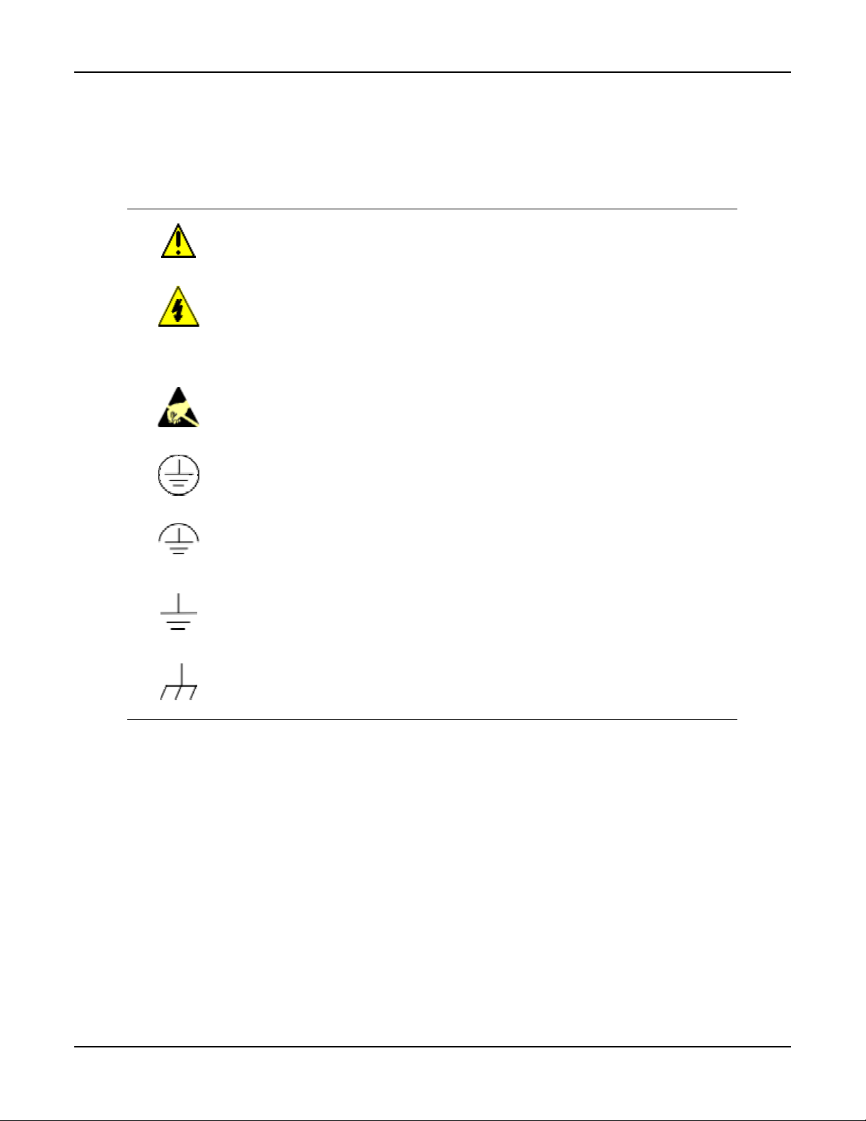
Symbol Definitions
The following table lists those symbols used in this document to denote certain conditions.
Symbol Definition
This CAUTION symbol on the equipment refers the user to the Product Manual for
additional information. This symbol appears next to required information in the manual.
WARNING
PERSONAL INJURY: Risk of electrical shock. This symbol warns the user of a
potential shock hazard where HAZARDOUS LIVE voltages greater than 30 Vrms, 42.4
Vpeak, or 60 VDC may be accessible. Failure to comply with these instructions
could result in death or serious injury.
ATTENTION, Electrostatic Discharge (ESD) hazards. Observe precautions for
handling electrostatic sensitive devices
Protective Earth (PE) terminal. Provided for connection of the protective earth (green
or green/yellow) supply system conductor.
Functional earth terminal. Used for non-safety purposes such as noise immunity
improvement. NOTE: This connection shall be bonded to protective earth at the source
of supply in accordance with national local electrical code requirements.
Earth Ground. Functional earth connection. NOTE: This connection shall be bonded to
Protective earth at the source of supply in accordance with national and local electrical
code requirements.
Chassis Ground. Identifies a connection to the chassis or frame of the equipment shall
be bonded to Protective Earth at the source of supply in accordance with national and
local electrical code requirements.
iv ST3000 Transmitter Quick Start Installation Guide 10/05
Page 5

Contents
1 MOUNTING THE TRANSMITTER......................................................................... 1
1.1 Typical Bracket mounted and Flange Mounted Installations .........................................................1
1.2 Bracket Mounting ...........................................................................................................................1
1.3 Flange Mounting.............................................................................................................................4
1.4 Flush Mounting...............................................................................................................................5
1.5 High Temperature Transmitter Mounting.......................................................................................5
1.6 Remote Seal Mounting ...................................................................................................................6
2 TRIM THE TRANSMITTER ...................................................................................7
2.1 Procedure to Trim the Transmitter..................................................................................................7
3 SET THE JUMPERS..............................................................................................8
3.1 Changing Default Failsafe Direction ..............................................................................................8
3.2 Optional Write Protect Jumper .......................................................................................................9
4 CONNECT THE WIRING AND POWER UP........................................................ 10
4.1 Summary.......................................................................................................................................10
4.2 Wiring Connections ......................................................................................................................11
4.3 Lightning Protection .....................................................................................................................11
4.4 Additional Considerations for Wiring SMV 3000 Transmitter ....................................................12
5 CERTIFICATIONS............................................................................................... 13
5.1 Product Certifications ...................................................................................................................13
5.1.1 Approved Manufacturing Locations ..................................................................................13
5.1.2 European Directive Information ........................................................................................13
5.2 Hazardous Location Certifications................................................................................................14
5.2.1 North American Certifications...........................................................................................14
5.2.2 Atex Certification...............................................................................................................16
5.2.3 SA (Standards Australia) Certification, Australia..............................................................19
5.2.4 Russia Certification, Russia ...............................................................................................19
5.2.5 INMETRO Certification, Brazil .........................................................................................19
10/05 ST3000 Transmitter Quick Start Installation Guide v
Page 6

vi ST3000 Transmitter Quick Start Installation Guide 10/05
Page 7

A
1 Mounting The Transmitter
1.1 Typical Bracket mounted and Flange Mounted Installations
ngle
Mounting
Bracket
Tank
Wall
Flange
Connection
Horizontal Pipe
Transmitter
Flange
Fla t
Mounting
Bracket
Figure 1
1.2 Bracket Mounting
Optional mounting bracket, see Figure 2.
Existing mounting bracket, see Figure 3.
Rotate the transmitter housing, see Figure 4.
Level a transmitter with small absolute or differential pressure spans, see Figure 5.
10/05 ST3000 Transmitter Quick Start Installation Guide 1
Page 8
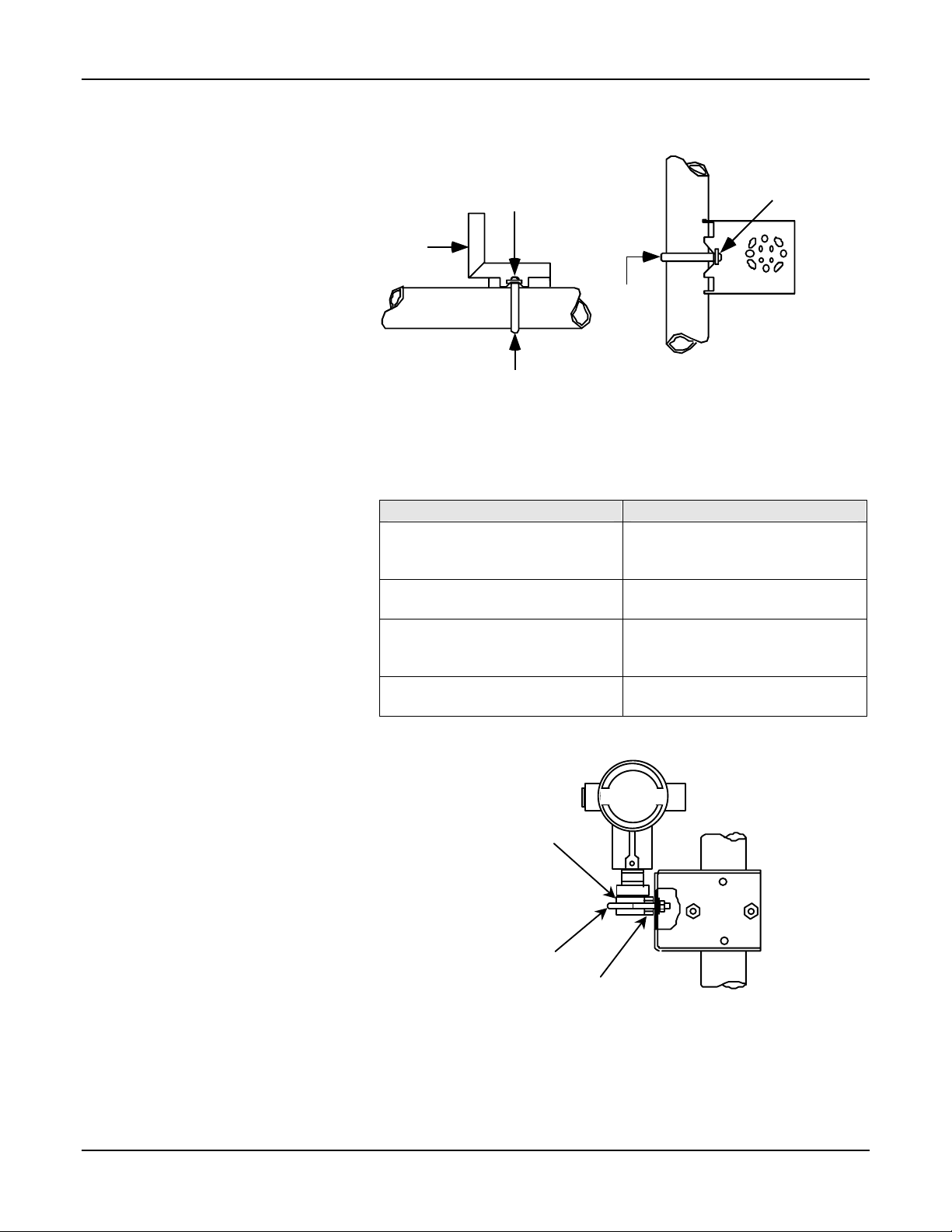
Optional Mounting Bracket
Position bracket on 2-inch (50.8
mm) or, and install “U” bolt
around pipe and through holes
in bracket. Secure with nuts and
lockwashers provided.
Figure 2 Example - Angle
mounting bracket secured to
horizontal or vertical pipe.
Mounting
Bracket
Horizontal Pipe
Nuts and
Lockwashers
U-Bolt
Nuts and
Lockwashers
Mounting
Bracket
Existing Mounting Bracket
Align appropriate mounting
holes in transmitter with holes in
bracket and secure with bolts
and washers provided.
NOTE: If the meter body is
hexagonal, you must use the
additional bracket supplied. If
meter body is round, discard
the bracket
Figure 3 Example – LGP model
transmitter mounted to optional
angle mounting bracket.
U-Bolt
Vertical Pipe
Figure 2
If Transmitter is…. Then….
DP type with double-ended
process heads and/or remote
seals
GP and AP with single-ended
head
In-line GP and AP (LGP model) Use smaller “U” bolt provided to
Dual head GP Use mounting holes in end of
LGP and LAP models
Use alternate mounting holes in
end of heads
Use mounting holes in side of
meter body
attach meter body to bracket
See Figure 3.
process head
Meter Body
Smaller
“U” bolt
Use bracket for
hexagonal meter body
Figure 3
2 ST3000 Transmitter Quick Start Installation Guide 10/05
Page 9
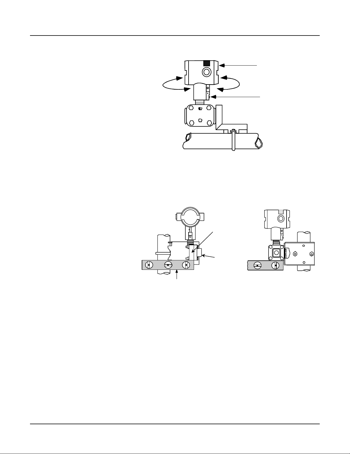
Rotating Transmitter Housing
Loosen set screw on outside
neck of transmitter one full turn.
Rotate Transmitter housing in
maximum of 180 degree
increment in left or right
direction from center to position
you require and tighten set
180 degrees
max.
180 degrees
max.
Electronics
Housing
Set Screw
screw (1.46 to 1.68 Nùm/13 to
15 lb-in).
Figure 4 Example – Rotating
Transmitter Housing.
Figure 4
Leveling Transmitters with Small Absolute or Differential Pressure Spans
Mounting position of these
transmitters is critical due to
the smaller transmitter spans.
To minimize these positional
effects on calibration (zero
shift), take the appropriate
mounting precautions that
follow for the given transmitter
model.
See Figure 5 and 5a for
suggestions on how to level
the transmitter using a spirit
balance.
To perform a Zero Trim after
leveling, refer to Section 2.
Models STA122 and STA922
Center
Section
Process
Head
Position spirit balance on
center section of meter
body only.
For a model STA122 or STA922 transmitter, you must ensure that the
transmitter is vertical when mounting it. You do this by leveling the
transmitter side-to-side and front-to-back.
Figure 5
10/05 ST3000 Transmitter Quick Start Installation Guide 3
Page 10
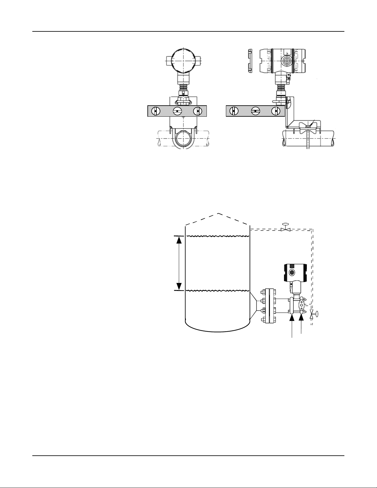
1.3 Flange Mounting
Mount transmitter vertically to assure best accuracy. Position spirit
balance on pressure connection surface of AP body.
Figure 5a
To mount a flange mounted
transmitter model, bolt the
transmitter’s flange to the flange
pipe on the wall of the tank.
On insulated tanks, remove
enough insulation to
accommodate the flange
extension.
It is the End User’s
responsibility to provide a flange
gasket and mounting hardware
that are suitable for the
transmitter’s service condition.
To prevent degradation of
performance in Flush-Mounted
Flanged Transmitters, exercise
care to ensure that the internal
diameter of the flange gasket
does not obstruct the sensing
diaphragm.
To prevent degradation of
performance in Extended Mount
Flanged Transmitters, ensure
that there is sufficient clearance
in front of the sensing
diaphragm body.
Variable
Head H1
Maximum Level
Minimum Level
Attention: Dotted area indicates use
with closed tank with reference leg.
Figure 6
HP Side
mounted
to tank
Reference
Leg
LP Side vented
to atmosphere
4 ST3000 Transmitter Quick Start Installation Guide 10/05
Page 11

1.4 Flush Mounting
To mount a flush mounted transmitter
model, cut a hole for a 1-inch standard
pipe in the tank or pipe where the
transmitter is to be mounted.
See Figure 7
Weld the 1-inch mounting sleeve to the
wall of the tank or to the hole cut on the
pipe. Insert the meter body of the
transmitter into the mounting sleeve and
secure with the locking bolt. Tighten the
bolt to a torque of 6,4 Nm+/- 0,30 Nm
[4.7 ft.-lbs. +/- 0.2 ft.-lbs.]
Once the transmitter is mounted, the
transmitter housing can be rotated to
the desired position. See Figure 4
On insulated tanks, remove enough
insulation to accommodate the
mounting sleeve.
1.5 High Temperature Transmitter Mounting
You can mount the high temperature
transmitter directly to the process flange
connection or the process piping. See
Figure 8.
To mount a flange mounted transmitter
model, bolt the transmitter’s flange to
the flange on the wall of the tank or
process pipe.
Tank
Wall
1” Pipe Mount 316 SS Weld Nipple
(standard option)
Figure 7
It is the End User’s responsibility to
provide a flange gasket and mounting
hardware that are suitable for the
transmitter’s service condition.
Once the transmitter is mounted, the
transmitter housing can be rotated to
Flange
Connection
Transmitter
Flange
the desired position. See Figure 4
On insulated tanks, remove enough
insulation to accommodate the
mounting sleeve.
Process Pipe
1/2" NPT
Connection
Figure 8
10/05 ST3000 Transmitter Quick Start Installation Guide 5
Page 12

1.6 Remote Seal Mounting
Mount the transmitter at a
remote distance determined by
length of capiliary tubing.
NOTE: The combination of tank
vacuum and high pressure
capillary head effect should not
exceed 9 psi (300 mm Hg)
absolute.
On insulated tanks, remove
enough insulation to
accommodate the mounting
sleeve.
Figure 3 Example – Typical
Remote Seal Transmitter
installation
If Transmitter Model Number
is….
Then connect remote seal
on….
STR93D or STR12D high pressure (HP) side of
transmitter to lower flange
mounting on tank wall for
variable head H1.
STR13D low pressure (LP) side of
transmitter to lower flange
mounting on tank wall for
variable head H1.
STR93D or STR12D low pressure (LP) side of
transmitter to upper flange
mounting on tank wall for fixed
or constant head H2.
STR13D high pressure (HP) side of
transmitter to upper flange
mounting on tank wall for fixed
or constant head H2.
It is the End User’s responsibility to provide a flange gasket and
mounting hardware that are suitable for the transmitter’s service
condition
LP Side
- Model STR93D
- Model STR12D
HP Side
- Model STR13D
Maximum Level
H2
Fixed
Ref. Leg
Minimum Level
HP Side
- Model STR93D
- Model STR12D
LP Side
- Model STR13D
Variable
Head H1
Figure 9
6 ST3000 Transmitter Quick Start Installation Guide 10/05
Page 13

2 Trim the Transmitter
2.1 Procedure to Trim the Transmitter
For a transmitter with a small
differential pressure span, you
must ensure that the transmitter is
vertical when mounting it. You do
this by leveling the transmitter
side-to-side and front-to-back. See
Figure 5 for suggestions on how to
level the transmitter using a spirit
balance. You must also zero the
transmitter by following the steps in
this table.
Step Action
1
2
3
4
5
6
7
Attach the transmitter to the mounting bracket but do not
completely tighten the mounting bolts
Connect a tube between the input connections in the high
pressure (HP) and low pressure (LP) heads to eliminate
the affects of any surrounding air currents.
Connect 24 Vdc power to the transmitter and connect a
digital voltmeter or SFC to read the transmitter’s output or
connect a voltmeter across the 250 ohm resistor, if desired.
Use applicable communicator to establish communications
with the transmitter. For DE transmitter use SFC, SCT, or
MCT. For Hart, use MCT or other Hart Communicator with
applicable Honeywell DD's. For Fieldbus, use NI FBUS
tools with applicable Honeywell DD's.
While reading the transmitter’s output on a communication
tool or a voltmeter, position the transmitter so the output
reading is at or near zero, then completely tighten the
mounting bolts.
Do an input zero correct function using the communication
tool. This corrects the transmitter for any minor error that
may occur after the mounting bolts are tightened.
Remove the tube from between the input connections, the
power, and the digital voltmeter or communication tool.
10/05 ST3000 Transmitter Quick Start Installation Guide 7
Page 14

3 Set the Jumpers
3.1 Changing Default Failsafe Direction
Transmitters are shipped with a
default failsafe direction of upscale.
This means that the transmitter’s
output will be driven upscale
(maximum output) when the
transmitter detects a critical status.
You can change the direction from
upscale to downscale (minimum
output) by cutting jumper W1 on
the printed wiring assembly. If your
transmitter is operating in the
analog mode, an upscale failsafe
action will drive the transmitter’s
output to greater than 21 mA or a
downscale action will drive its
output to less than 3.8 mA.
If your transmitter is operating in
the DE mode an upscale failsafe
action will cause the transmitter to
generate a “+ infinity” digital signal,
or a downscale failsafe action will
cause it to generate a “– infinity”
digital signal. The STIMV IOP
module interprets either signal as
“not a number” and initiates its own
configured failsafe action for the
control system. The STDC initiates
the failsafe mode configured
through the transmitter when either
signal is generated.
NOTE: The failsafe direction
display that you can access
through the SFC only shows the
state of the failsafe jumper in the
transmitter as it correlates to
analog transmitter operation. The
failsafe action of the digital control
system may be configured to
operate differently than indicated
by the state of the jumper in the
transmitter.
Step Action
1
2
3
4
5
Failsafe
Direction
Jumper
Figure 10
ATTENTION: Electrostatic Discharge (ESD) hazards.
Observe precautions for handling electrostatic sensitive
devices
With transmitter on bench and no power applied. Loosen
end-cap lock and unscrew end cap from electronics side of
transmitter housing.
If applicable, unsnap Local Smart Meter from PWA
mounting bracket and unplug cable from connector on
back of meter assembly.
Loosen two retaining screws and carefully pull mounting
bracket and PWA from housing.
Using retaining clip remove flex-tape connector from PWA
Remove 2-wire power connector from PWA, and then
remove PWA and mounting bracket assembly.
With component side of PWA facing you, locate failsafe
jumper W1 and cut it in half with small wire cutter such as
dykes. See Figure 10. This changes failsafe action from
upscale to downscale.
Reverse applicable previous steps to replace PWA.
Turn ON transmitter power.
Power
Connector
Meter
Connector
8 ST3000 Transmitter Quick Start Installation Guide 10/05
Page 15

3.2 Optional Write Protect Jumper
The ST 3000 transmitters are
available with a “write protect
option”. When the write
protect option is ordered,
transmitters are shipped with
a default jumper position for
read-only. This means that
the transmitter’s configuration
database can not be
overwritten. To allow
read/write access, the jumper
can be moved to the
read/write position. When the
write protect option is not
ordered access is read/write.
There is no need to check the
jumper position unless you
want to change it. Refer to
the steps in the table in
section 3.1 to remove the
PWA from the transmitter and
Figure 11 to reposition the
jumper.
Failsafe
Direction
Jumper
Figure 11
ATTENTION: Electrostatic Discharge (ESD) hazards.
Observe precautions for handling electrostatic sensitive
devices
W
R
Read and
Write
Read Only
Power
Connector
Meter
Connector
10/05 ST3000 Transmitter Quick Start Installation Guide 9
Page 16

4 Connect the Wiring and Power Up
4.1 Summary
The transmitter is designed to
operate in a two-wire
power/current loop with loop
resistance and power supply
voltage within the operating
range shown in Figure 12.
Loop wiring is connected to the
transmitter by simply attaching
the positive (+) and negative (–)
loop wires to the positive (+)
and negative (–) SIGNAL screw
terminals on the terminal block
in the transmitter’s electronics
housing shown in the table in
Section 4.2.
Each transmitter includes an
internal ground terminal to
connect the transmitter to earth
ground. A ground terminal can
be optionally added to the
outside of the electronics
housing. While it is not
necessary to ground the
transmitter for proper operation,
we suggest that you do so to
minimize the possible effects of
“noise” on the output signal and
provide additional protection
against lightning and static
discharge damage.
1440
1200
Loop
Resistance
(ohms)
800
650
450
250
0 10.8 16.28 20.63 25 28.3 37.0 42.4
Operating Voltage (Vdc)
Figure 12
= Operating
Area
NOTE: A minimum of
250 0hms of loop
resistance is
necessary to support
communications. Loop
resistance equals
barrier resistance plus
wire resistance plus
receiver resistance.
21012
10 ST3000 Transmitter Quick Start Installation Guide 10/05
Page 17

4.2 Wiring Connections
This procedure shows the steps for
connecting power to the
transmitter.
For loop wiring and external
wiring diagrams, refer to the
installation drawings presented in
the Transmitter Manual.
Detailed drawings are provided for
transmitter installation in nonintrinsically safe areas and for
intrinsically safe loops in
hazardous area locations.
ATTENTION
All wiring must comply with
local codes, regulations, and
ordinances.
If you will be using the
transmitter in a hazardous area,
be sure to review the hazardous
location reference data included
in Appendix B of the transmitter
manual before operating the
transmitter.
Step Action
1
Loosen end-cap lock using a 1.5 mm allen wrench and
remove end-cap cover from terminal block end of
transmitter housing.
2
Feed loop power leads through one of conduit entrances
on either side of transmitter housing. Plug whichever
entrance you do not use.
ATTENTION
The transmitter accepts up to 16 AWG
wire.
3
Observing polarity, connect positive loop power lead to
SIGNAL + terminal and negative loop power lead to
SIGNAL – terminal.
EXAMPLE - CONNECTING LOOP POWER TO
TRANSMITTER.
3-screw terminal block
Loop
Power
+
-
T
S
E
+
T
+
L
A
N
G
I
S
-
5-screw terminal block (option LP)
Loop
Power
4
Replace end-cap, and tighten end-cap lock
L
A
+
N
G
+
-
I
S
L
-
R
E
T
E
M
L
A
+
-
N
G
I
-
S
+
T
S
E
-
T
+
-
.
4.3 Lightning Protection
When your transmitter is
equipped with optional lightning
protection, you must connect a
wire from the transmitter to
ground as shown in
Figure 13 to make the
protection effective. We
recommend that you use a size
8 (American Wire Gage) or
(8.37mm
2
) bare or green
covered wire.
Figure 13
10/05 ST3000 Transmitter Quick Start Installation Guide 11
Electronics
Housing
Connect to
Earth Ground
Page 18

4.4 Additional Considerations for Wiring SMV 3000 Transmitter
Figure 14 SMV 3000 Transmitter Terminal Block
Connect RTD leads to the TC terminals 1, 2, 3, and 4 as appropriate for the given probe type.
Figure 15 RTD Input Wiring Connections.
Connect thermocouple leads to terminals 1 (–) and 3 (+), observing polarity.
Figure 16 Thermocouple Input Wiring Connections.
12 ST3000 Transmitter Quick Start Installation Guide 10/05
Page 19

5 Certifications
5.1 Product Certifications
5.1.1 Approved Manufacturing Locations
Honeywell Industrial Measurement & Control
Honeywell International Inc.
2500 West Union Hills Drive
Phoenix, AZ 85027 USA
Honeywell (Tianjin) Limited
66 BaiHe Road, Tianjin EconomicTechnological Development Area
Tianjin, 300457, P.R. China
TATA Honeywell Limited
55-A, 8 & 9 Hadapsar Industrial Estate
Pune 411 013, India
5.1.2 European Directive Information
The EC Declarations of Conformity for all applicable directives for this product can be found on the
Honeywell website at www.honeywell.com/imc. A hard copy may be obtained by contacting your local
Honeywell sales office.
European Pressure Equipment Directive (PED) 97/23/EC
The ST 3000 pressure transmitters are in conformity with the essential requirements of the PED. A formal
statement from TÜV Industry Service Group of TÜV America, Inc., a division of TÜV Süddeutschland, a
Notified Body regarding the Pressure Equipment Directive, is available upon request.
Electromagnetic Compatibility (EMC) 89/336/EEC
All ST 3000 Pressure Transmitters
EN 50081-1: 1992; EN 50082-2: 1995;
EN 61326: 1997 / A1: 1998 – Industrial
10/05 ST3000 Transmitter Quick Start Installation Guide 13
Page 20

5.2 Hazardous Location Certifications
5.2.1 North American Certifications
FM Approvals (USA)
Code Comm Description
1C
4-20 mA / DE
4-20 mA / HART
FOUNDATION™
Fieldbus
Intrinsically Safe for Class I, Division 1, Groups A, B, C, D, E, F & G,
ENTITY, when installed per Honeywell Control Drawing 51204241.
Nonincendive Class 1, Division 2, Groups A, B, C & D
T4, (Ta ≤ 93°C);
Explosionproof for Class I, Division 1, Groups A, B, C & D;
Dust-Ignitionproof for Class II, Division 1, Groups E, F & G;
Suitable for Class II, Division 2, Groups F & G and Class III
T5, (Ta ≤ 93°C); Seal all conduits within 18 inches, Group A only;
Enclosure Type 4X, IP 66/67
Intrinsically Safe for Class I, Division 1, Groups A, B, C, D, E, F & G,
ENTITY, when installed per Honeywell Control Drawing 51205784.
Nonincendive for Class 1, Division 2, Groups A, B, C & D
T4, (Ta ≤ 93°C)
Explosionproof for Class I, Division 1, Groups A, B, C & D
Dust-Ignitionproof for Class II, Division 1, Groups E, F & G
Suitable for Class II, Division 2, Groups F & G and Class III
T5, (Ta ≤ 93°C); Seal all conduits within 18 inches, Group A only;
Enclosure Type 4X, IP 66/67
Intrinsically Safe for Class I, Division 1, Groups A, B, C, D, E, F & G,
ENTITY, when installed per Honeywell Control Drawing 51204301.
Nonincendive Class 1, Division 2, Groups A, B, C & D
T4, (Ta -40 to 40°C), T3A, (Ta -40 to 93°C)
Explosionproof Class I, Division 1, Groups A, B, C & D
Dust-Ignitionproof, Class II, Division 1, Groups E, F & G
Suitable for Class II, Division 2, Groups F & G and Class III
T4, (Ta -40 to 40°C), T3A, (Ta -40 to 93°C); Seal all conduits within 18
inches, Group A only; Enclosure Type 4X, IP 66/67
14 ST3000 Transmitter Quick Start Installation Guide 10/05
Page 21

Canadian Standards Association (CSA)
Code Comm Description
2J
4-20 mA / DE
4-20 mA / HART
FOUNDATION™
Fieldbus
Intrinsically Safe, Class I, Division 1, Groups A, B, C & D, Class II, Division
1, Groups E, F & G, Class III, Divisions 1 & 2, when installed per
Honeywell Control Drawing 51204242
Non-Incendive Class I, Division 2, Groups A, B, C & D, Class II, Division 2,
Groups E, F & G and Class III, Division 2
T4 (Ta ≤ 93°C)
Explosion Proof for Class I, Division 1, Groups B, C & D
Dust-Ignitionproof for Class II, Division 1, Groups E, F & G and Class III,
Division 1
T4 (Ta ≤ 93°C) ; Enclosure Type 4X, IP 66/67
Intrinsically Safe, Class I, Division 1, Groups A, B, C & D, Class II, Division
1, Groups E, F & G, Class III, Divisions 1 & 2, when installed per
Honeywell Control Drawing 51450806
Non-Incendive Class I, Division 2, Groups A, B, C & D, Class II, Division 2,
Groups E, F & G and Class III, Division 2
T4 (Ta ≤ 93°C)
Explosion Proof for Class I, Division 1, Groups B, C & D
Dust-Ignitionproof for Class II, Division 1, Groups E, F & G and Class III,
Division 1
T4 (Ta ≤ 93°C) ; Enclosure Type 4X, IP 66/67
Intrinsically Safe, Class I, Division 1, Groups A, B, C & D, Class II, Division
1, Groups E, F & G, Class III, Divisions 1 & 2, when installed per
Honeywell Control Drawing 51204302.
Nonincendive Class 1, Division 2, Groups A, B, C & D
T4, (Ta -40 to 40°C), T3A, (Ta -40 to 93°C)
Explosion Proof Class I, Division 1, Groups A, B, C & D
Dust-Ignitionproof, Class II, Division 1, Groups E, F & G
Suitable for Class II, Division 2, Groups F & G and Class III
T4, (Ta -40 to 40°C), T3A, (Ta -40 to 93°C) ; Enclosure Type 4X, IP 66/67
10/05 ST3000 Transmitter Quick Start Installation Guide 15
Page 22

5.2.2 Atex Certification
ATEX Certification, Europe (Assembled in Phoenix, AZ USA)
Code Comm Description
3D ALL
3N ALL
3S 4-20 mA / DE
3S 4-20 mA / HART
LCIE 02 ATEX 6099, Ex II 2 G - Flameproof, EEx d IIC T5, (Ta -50 to
93°C), T6, (Ta -50 to 78°C); Enclosure IP 66/67
ATEX-Z2-51452622, Ex II 3 G - Non-Sparking, EEx nA, IIC, T5, (Ta -40 to
93°C), T6, (Ta -40 to 78°C); Enclosure IP 66/67
Special Conditions for Safe Use:
The installation of this equipment in Zone 2 hazardous areas must comply
with IEC 60079-14, EN 50021 and/or valid national standards for
installation and operation.
The power supply voltage cannot exceed the 42 Vdc maximum for 4-20
mA analog, DE and HART equipment, and 24 Vdc for Fieldbus equipment.
The electronic assemblies in these units are non-repairable items and if
faulty must be replaced. The electrical power supply must be switched off
before any replacement and during any time that the wiring terminations
are being connected or disconnected.
The technical data supplied by the manufacturer must be adhered to.
LCIE 02 ATEX 6100X, Ex II 1 G - Intrinsically Safe, EEx ia IIC T4, (Ta -50
to 93°C), T5, (Ta -50 to 85°C), T6, (Ta -50 to 70°C); Enclosure IP 66/67
Special Conditions for Safe Use (X):
The transmitter is intrinsically safe apparatus; it may be installed in
potentially explosive atmospheres.
For safety purposes, terminals + and – must be considered as eventually
connected to ground.
The power terminals (+ and -) must only be connected to certified
associated intrinsically safe equipment. The combinations must be
compatible in accordance with intrinsic safety rules.
LCIE 02 ATEX 6101X, Ex II 1 G - Intrinsically Safe, EEx ia IIC T4, (Ta -50
to 93°C), T5, (Ta -50 to 63°C), T6, (Ta -50 to 48°C); Enclosure IP 66/67
Special Conditions for Safe Use (X):
The transmitter is intrinsically safe apparatus; it may be installed in
potentially explosive atmospheres.
For safety purposes, terminals + and – must be considered as eventually
connected to ground.
The power terminals (+ and -) must only be connected to certified
associated intrinsically safe equipment. The combinations must be
compatible in accordance with intrinsic safety rules.
16 ST3000 Transmitter Quick Start Installation Guide 10/05
Page 23

Code Comm Description
3S FOUNDATION™
Fieldbus
LCIE 03 ATEX 6175X, Ex II 1 G - Intrinsically Safe, EEx ia IIC T3, (Ta -50
to 93°C), T4, (Ta -50 to 40°C); Enclosure IP 66/67
Special Conditions for Safe Use (X):
The transmitter is intrinsically safe apparatus; it may be installed in
potentially explosive atmospheres.
For safety purposes, terminals + and – must be considered as eventually
connected to ground.
The power terminals (+ and -) must only be connected to certified
associated intrinsically safe equipment. The combinations must be
compatible in accordance with intrinsic safety rules.
The electrical parameters of certified equipment which can be connected
to the transmitter exceed the following values:
Uo ≤ 24 V; Io ≤ 250 mA; Po ≤ 1,2 W.
ATEX Certification, Europe (Assembled in Tianjin, P.R. China)
Code Comm Description
3D ALL
3N ALL
3S 4-20 mA / DE
LCIE 03 ATEX 6396, Ex II 2 G - Flameproof, EEx d IIC T5, (Ta -50 to
93°C), T6, (Ta -50 to 78°C); Enclosure IP 66/67
ATEX-Z2-51453605, Ex II 3 G - Non-Sparking, EEx nA, IIC, T5, (Ta -40 to
93°C), T6, (Ta -40 to 78°C); Enclosure IP 66/67
Special Conditions for Safe Use:
The installation of this equipment in Zone 2 hazardous areas must comply
with IEC 60079-14, EN 50021 and/or valid national standards for
installation and operation.
The power supply voltage cannot exceed the 42 Vdc maximum for 4-20
mA analog, DE and HART equipment, and 24 Vdc for Fieldbus equipment.
The electronic assemblies in these units are non-repairable items and if
faulty must be replaced. The electrical power supply must be switched off
before any replacement and during any time that the wiring terminations
are being connected or disconnected.
The technical data supplied by the manufacturer must be adhered to.
LCIE 03 ATEX 6397X, Ex II 1 G - Intrinsically Safe, EEx ia IIC T4, (Ta -50
to 93°C), T5, (Ta -50 to 85°C), T6, (Ta -50 to 70°C); Enclosure IP 66/67
Special Conditions for Safe Use (X):
The transmitter is intrinsically safe apparatus; it may be installed in
potentially explosive atmospheres.
For safety purposes, terminals + and – must be considered as eventually
connected to ground.
The power terminals (+ and -) must only be connected to certified
associated intrinsically safe equipment. The combinations must be
compatible in accordance with intrinsic safety rules.
10/05 ST3000 Transmitter Quick Start Installation Guide 17
Page 24

Code Comm Description
3S 4-20 mA / HART
LCIE 03 ATEX 6398X, Ex II 1 G – Intrinsically Safe, Eex ia IIC T4, (Ta –50
to 93°C), T5, (Ta –50 to 63°C), T6, (Ta –50 to 48°C); Enclosure IP 66/67
Special Conditions for Safe Use (X):
The transmitter is intrinsically safe apparatus; it may be installed in
potentially explosive atmospheres.
For safety purposes, terminals + and – must be considered as eventually
connected to ground.
The power terminals (+ and -) must only be connected to certified
associated intrinsically safe equipment. The combinations must be
compatible in accordance with intrinsic safety rules.
3S FOUNDATION™
Fieldbus
LCIE 04 ATEX 6118X, Ex II 1 G – Intrinsically Safe, Eex ia IIC T3, (Ta –50
to 93°C), T4, (Ta –50 to 40°C); Enclosure IP 66/67
Special Conditions for Safe Use (X):
The transmitter is intrinsically safe apparatus; it may be installed in
potentially explosive atmospheres.
For safety purposes, terminals + and – must be considered as eventually
connected to ground.
The power terminals (+ and -) must only be connected to certified
associated intrinsically safe equipment. The combinations must be
compatible in accordance with intrinsic safety rules.
The electrical parameters of certified equipment which can be connected
to the transmitter exceed the following values:
Uo ≤ 24 V; Io ≤ 250 mA; Po ≤ 1,2 W.
ATEX Certification (Apparatus Marked with Multiple Types of Protection)
Code Description
3H
The 3H code provides a certification nameplate listing three types of
protection: 3D – flameproof (zone 1), 3N – non-sparking (zone 2), and 3S
– intrinsically safe (zones 0/1).
The user must determine the type of protection required for installation of
the equipment. The user shall then permanently mark the box [D]
adjacent to the type of protection used on the equipment certification
nameplate. Once a type of protection has been checked on the
nameplate, the equipment must not be reinstalled using any of the other
unmarked certification types.
18 ST3000 Transmitter Quick Start Installation Guide 10/05
Page 25

5.2.3 SA (Standards Australia) Certification, Australia
Code Comm Description
4G 4-20 mA / DE
4N 4-20 mA / DE
AUS-Ex 1371X-06, Intrinsically Safe, Ex ia IIC T4 (Ta ≤ 93°C); NonSparking, Ex n IIC T4 (Ta ≤ 93°C); Enclosure IP 66/67
Special Conditions for Safe Use (X):
The system installation instructions shall be followed when installing this
equipment.
Cables are to be connected using a cable gland with IP rating of IP66 or
greater.
If the temperature under rated conditions exceeds 75°C at the cable or
conduit entry point or at the branching point of the conductors, a label shall
be provided on the outside of the unit as a guide to the selection of the
cable or the wiring in the conduit.
AUS Ex 3781X, Non-Sparking, Ex n IIC T4 (Ta ≤ 93°C); Enclosure IP
66/67
Special Conditions for Safe Use (X):
The Maximum Input Voltage must not exceed 42 V.
The system installation instructions shall be followed when installing this
equipment.
Tampering and replacement with non-factory components may adversely
affect the safe use of the system.
Cables are to be connected using a cable gland with IP rating of IP66 or
greater.
If the temperature under rated conditions exceeds 75°C at the cable or
conduit entry point or at the branching point of the conductors, a label shall
be provided on the outside of the unit as a guide to the selection of the
cable or the wiring in the conduit.
5.2.4 Russia Certification, Russia
Code Comm Description
5D ALL
5S ALL
RU-230, Flameproof, 1ExdIICT6X, T6 (Ta ≤ 93°C), Enclosure IP 66/67
RU-306, Intrinsically Safe, 0ExiaIICT5X, T5 (Ta ≤ 93°C), Enclosure IP
66/67
5.2.5 INMETRO Certification, Brazil
Code Comm Description
6D ALL
10/05 ST3000 Transmitter Quick Start Installation Guide 19
INMETRO-2002EC02CP031, CERTSUP/INMETRO, Flameproof, Ex d IIC
T5, (Ta -50 to 93°C); Enclosure IP 66/67
Page 26

20 ST3000 Transmitter Quick Start Installation Guide 10/05
Page 27

ST 3000 Smart Pressure Transmitter,
Quick Start Installation Guide
Write-protect option
Overview
Approx.
Page # in
User
Manual
9
3.2 Optional Write Protect
Jumper
The ST3000 Pressure Transmitter (DE or HART) is now being shipped with a newly
designed printed wiring assembly (PWA) that allows user access to the optional write
protect jumper without removing the PWA. This version of the PWA is functionally
identical to the previous version, with the same performance and specifications. The
new version PWA differs only in location of the optional write protect jumper and the
associated bracket and hardware.
Section Description of Change
Do not remove the PWA as described in Section 3.1 Changing Default
Failsafe Direction. Instead, follow the following steps.
34-ST-99-44
10/6/05
Addendum
(to User Manual
34-ST-25-24)
ATTENTION: Electrostatic Discharge (ESD) hazards. Observe
precautions for handling electrostatic sensitive devices.
WARNING! PERSONAL INJURY: Risk of electrical shock.
Disconnect power before proceeding. HAZARDOUS LIVE voltages
greater than 30 Vrms, 42.4 Vpeak, or 60 VDC may be accessible.
Failure to comply with these instructions could result in death or
serious injury.
Step 1 Place transmitter on bench. Remove power. Loosen end-cap
lock and unscrew end-cap from electronics side of transmitter
housing.
Step 2 If applicable, unsnap local smart meter from PWA mounting
bracket.
Step 3 Find the write protect jumper shown in Figure 11 below.
Position the jumper for read-only or read/write.
Step 4 Reverse applicable previous steps to install smart meter and
end-cap.
Step 5 Re-connect transmitter power.
10/6/05 34-ST-99-44 (Addendum to 34-ST-25-24) 1 of 2
Page 28

Approx.
Page # in
User
Manual
Section Description of Change
Figure 11
2 of 2 34-ST-99-44 (Addendum to 34-ST-25-24) 10/6/05
Page 29

Page 30

Page 31

Page 32

Industrial Measurement and Control
Honeywell International, Inc
2500 Union Hills Drive
Phoenix, Arizona 85027
34-ST-25-24 Rev. 3 10 05 Printed in USA www.honeywell.com/imc
 Loading...