

Page 1

Release 100.3
Safety Manager
Safety Manual
EP-SM.MAN.6283
100.3
25 January 2005
Page 2

Document Release Date
EP-SM.MAN.6283 100.3 January 2005
Notice
This document contains Honeywell proprietary information. Information
contained herein is to be used solely for the purpose submitted, and no part of this
document or its contents shall be reproduced, published, or disclosed to a third
party without the express permission of Honeywell Safety Management Systems.
While this information is presented in good faith and believed to be accurate,
Honeywell disclaims the implied warranties of merchantability and fitness for a
purpose and makes no express warranties except as may be stated in its written
agreement with and for its customer.
In no event is Honeywell liable to anyone for any direct, special, or consequential
damages. The information and specifications in this document are subject to
change without notice.
Copyright 2004 – Honeywell Safety Management Systems, a division of
Honeywell Aerospace B.V.
Honeywell trademarks
Safety Manager
Experion PKS
U.S. registered trademarks of Honeywell International Inc.
™
is a trademark of Honeywell International Inc.
®
, PlantScape®, SafeBrowse®, TotalPlant® and TDC 3000® are
Other trademarks
Microsoft and SQL Server are either registered trademarks or trademarks of
Microsoft Corporation in the United States and/or other countries.
Trademarks that appear in this document are used only to the benefit of the
trademark owner, with no intention of trademark infringement.
ii
Page 3

Support and other contacts
United States and Canada
Contact: Honeywell IAC Solution Support Center
Phone: 1-800 822-7673. In Arizona: (602) 313-5558
Facsimile: (602) 313-5476
Mail: Honeywell IS TAC, MS P13
Europe
Contact: Honeywell PACE TAC
Phone: +32-2-728-2657
Facsimile: +32-2-728-2278
Mail: Honeywell PACE TAC
Calls are answered by dispatcher between 6:00 am and 4:00 pm Mountain
Standard Time. Emergency calls outside normal working hours are
received by an answering service and returned within one hour.
2500 West Union Hills Drive
Phoenix, AZ, 85027
Avenue du Bourget, 1
B-1140 Brussels, Belgium
Pacific
Contact: Honeywell Global TAC - Pacific
Phone: 1300-300-4822 (toll free within Australia)
+61-2-9353-7255 (outside Australia)
Facsimile: +61-2-9353-8044
Mail: Honeywell Global TAC - Pacific
5 Thomas Holt Drive
North Ryde, NSW, 2113, Australia
Email GTAC@honeywell.com
iii
Page 4

India
Contact: Honeywell Global TAC - India
Phone: +91-20-687-5531
Facsimile: +91-20-687-9404
Mail: TATA Honeywell Ltd.
55 A8 & 9, Hadapsar Industrial
Hadapsar, Pune -411 013, India
Email Global-TAC-India@honeywell.com
Korea
Contact: Honeywell Global TAC - Korea
Phone: +82-2-799-6317
+82-11-743-6016
Facsimile: +82-2-792-9015
Mail: Honeywell IAC SBE, CRC
17F, Kikje Center B/D,
191, Hangangro-2Ga
Yongsan-gu, Seoul, 140-702, Korea
Email Global-TAC-Korea@honeywell.com
People’s Republic of China
Contact: Honeywell Global TAC - China
Phone: +86-10-8458-3280 ext. 361
Mail: Honeywell Tianjin Limited
17 B/F Eagle Plaza
26 Xiaoyhun Road
Chaoyang District
Beijing 100016, People's Republic of China
Email Global-TAC-China@honeywell.com
iv
Page 5

Singapore
Contact: Honeywell Global TAC - South East Asia
Phone: +65-580-3500
Facsimile: +65-580-3501
+65-445-3033
Mail: Honeywell Private Limited
Honeywell Building
17, Changi Business Park Central 1
Singapore 486073
Email GTAC-SEA@honeywell.com
Tai wan
Contact: Honeywell Global TAC - Taiwan
Phone: +886-7-323-5900
Facsimile: +886-7-323-5895
+886-7-322-6915
Mail: Honeywell Taiwan Ltd.
10F-2/366, Po Ai First Rd.
Kaohsiung, Taiwan, ROC
Email Global-TAC-Taiwan@honeywell.com
Japan
Contact: Honeywell Global TAC - Japan
Phone: +81-3-5440-1303
Facsimile: +81-3-5440-1430
Mail: Honeywell K.K
1-14-6 Shibaura Minato-Ku
Tokyo 105-0023
Japan
Email Global-TAC-JapanJA25@honeywell.com
Elsewhere
Call your nearest Honeywell office.
World Wide Web
Honeywell Solution Support Online:
http://www.ssol.acs.honeywell.com
v
Page 6

Training classes
Honeywell holds technical training classes on Safety Manager. These classes are
taught by experts in the field of process control systems. For more information
about these classes, contact your Honeywell representative, or see
http://www.automationcollege.com.
Related Documentation
The following guides are available for Safety Manager.
The guide in front of you is Safety Manual.
Guide Description
The Overview Guide This guide describes the general knowledge required, the
The Safety Manual This guide describes the specifications, design guidelines,
The Planning and Design
Guide
The Installation and Upgrade
Guide
The Troubleshooting and
Maintenance Guide
The System Administration
Guide
The Hardware Reference This guide specifies the hardware components that build a
The Software Reference This guide specifies the software functions that build a
The On-line Modification
Guide
basic functions of, and the tasks related to Safety Manager.
and safety aspects related to Safety Manager.
This guide describes the tasks related to planning and
designing a Safety Manager project.
This guide describes the tasks related to installing,
replacing and upgrading hardware and software as part of
a Safety Manager project.
This guide describes the tasks related to troubleshooting
and maintaining Safety Manager.
This guide describes the task related to administrating the
computer systems used in a Safety Manager project.
Safety Manager project.
Safety Manager project and contains guidelines on how to
operate them.
This guide describes the theory, steps and tasks related to
upgrading Safety Builder and embedded software and
modifying an application online in a redundant Safety
Manager.
vi
Page 7

Task-oriented guides
A task-oriented guide provides both procedural and basic knowledge. A task can
inform the reader on how to perform the task in terms of steps to follow.
Additionally a task can describe what important considerations to make or what
options to choose from when performing a task.
A task-oriented guide lists the required skills and knowledge that people must
master to qualify for the described tasks.
It is common for task oriented guides to refer to reference guides for details.
Reference guides
A reference guide provides detailed information or solutions regarding its scope.
A reference guide is a Safety Manager related guide and provides background
information to support tasks as described in task-oriented guides.
A reference guide does not describe tasks in terms of how to perform the task in
terms of steps to follow.
Available electronic format
All guides are accessible via the Safety Manager Knowledge Builder; an Internet
Explorer based viewer with extensive search and indexing options.
The Knowledge Builder contains guides stored as:
• web pages
• Adobe PDF guides
The information stored on the Safety Manager Knowledge Builder CD-ROM can
be installed as stand-alone or merged with other Knowledge Builder booksets on
a server.
Conventions
Symbols
The following symbols are used in Safety Manager documentation:
Attention
This symbol is used for information that emphasizes or supplements important points of
the main text.
Tip
This symbol is used for useful, but not essential, suggestions.
vii
Page 8
Note
This symbol is used to emphasize or supplement important points of the main text
Caution
This symbol warns of potential damage, such as corruption of the database.
Warning
This symbol warns of potentially hazardous situation, which, if not avoided, could result
in serious injury or death.
ESD
This symbol warns for danger of an electro-static discharge to which equipment may be
sensitive
Fonts
The following fonts are used in Safety Manager documentation:
Emphasis
• “... inform the reader on how to perform
the task in terms of...”
• “...see the Overview Guide”
Label
“The Advanced tab of the Properties
window has..”
Steps
Take the following steps:
1. Create a plant and set its properties.
2. ....
Value
“Low is the fault reaction state for
digital inputs and digital outputs.”
Variable
“The syntax is: filename [-s] [-p]“
http://www.honeywellsms.com This font is used to identify a URL, directing
Emphasised text is used to:
• emphasise important words in the text,
• identify document titles.
This font is used to identify labels.
Labels are used for Dialog box labels, menu
items, names of properties, and so on.
This font is used to identify steps.
Steps indicate the course of action that must
be adhered to, to achieve a certain goal.
This font is used to indicate a value.
Value is a variable that the reader must
resolve by choosing a pre-defined state.
This font is used to identify a variable.
Variables are used in syntax and code
examples.
a reader to a website that can be referred to.
viii
Page 9

Contents
1The Safety Manual 1
Content of Safety Manual . . . . . . . . . . . . . . . . . . . . . . . . . . . . . . . . . . . . . . . . . . . . . . . . . . . . . . . 2
Basic skills and knowledge . . . . . . . . . . . . . . . . . . . . . . . . . . . . . . . . . . . . . . . . . . . . . . . . . . . . . . 3
Prerequisite skills. . . . . . . . . . . . . . . . . . . . . . . . . . . . . . . . . . . . . . . . . . . . . . . . . . . . . . . . 3
Training . . . . . . . . . . . . . . . . . . . . . . . . . . . . . . . . . . . . . . . . . . . . . . . . . . . . . . . . . . . . . . . 3
Safety standards for Process & Equipment Under Control (PUC, EUC) . . . . . . . . . . . . . . . . . . . 4
Safety Integrity Level (SIL) . . . . . . . . . . . . . . . . . . . . . . . . . . . . . . . . . . . . . . . . . . . . . . . 4
Equipment Under Control (EUC) . . . . . . . . . . . . . . . . . . . . . . . . . . . . . . . . . . . . . . . . . . . 4
Process Under Control (PUC) . . . . . . . . . . . . . . . . . . . . . . . . . . . . . . . . . . . . . . . . . . . . . . 5
Application design conform IEC 61131-3. . . . . . . . . . . . . . . . . . . . . . . . . . . . . . . . . . . . . . . . . . . 6
The IEC 61508 and IEC 61511 standards . . . . . . . . . . . . . . . . . . . . . . . . . . . . . . . . . . . . . . . . . . . 7
2Introduction 9
System overview . . . . . . . . . . . . . . . . . . . . . . . . . . . . . . . . . . . . . . . . . . . . . . . . . . . . . . . . . . . . . 10
Certification. . . . . . . . . . . . . . . . . . . . . . . . . . . . . . . . . . . . . . . . . . . . . . . . . . . . . . . . . . . . . . . . . 11
Standards compliance . . . . . . . . . . . . . . . . . . . . . . . . . . . . . . . . . . . . . . . . . . . . . . . . . . . . . . . . . 13
EU Standards. . . . . . . . . . . . . . . . . . . . . . . . . . . . . . . . . . . . . . . . . . . . . . . . . . . . . . . . . . . . . . . . 16
CE marking . . . . . . . . . . . . . . . . . . . . . . . . . . . . . . . . . . . . . . . . . . . . . . . . . . . . . . . . . . . 16
EMC directive (89/336/EEC) . . . . . . . . . . . . . . . . . . . . . . . . . . . . . . . . . . . . . . . . . . . . . 17
Low voltage directive (73/23/EEC). . . . . . . . . . . . . . . . . . . . . . . . . . . . . . . . . . . . . . . . . 18
Machine safety directive (89/392/EEC)). . . . . . . . . . . . . . . . . . . . . . . . . . . . . . . . . . . . . 18
Definitions . . . . . . . . . . . . . . . . . . . . . . . . . . . . . . . . . . . . . . . . . . . . . . . . . . . . . . . . . . . . . . . . . . 20
3 Safety Manager architectures 29
Safety Manager basic architectures. . . . . . . . . . . . . . . . . . . . . . . . . . . . . . . . . . . . . . . . . . . . . . . 30
Dual Modular Redundant (DMR) architecture . . . . . . . . . . . . . . . . . . . . . . . . . . . . . . . . 30
Quadruple Modular Redundant (QMR) architecture . . . . . . . . . . . . . . . . . . . . . . . . . . . 31
System architectures . . . . . . . . . . . . . . . . . . . . . . . . . . . . . . . . . . . . . . . . . . . . . . . . . . . . 32
Overall safety life cycle. . . . . . . . . . . . . . . . . . . . . . . . . . . . . . . . . . . . . . . . . . . . . . . . . . . . . . . . 39
4 Design phases for an E/E/PE safety-related system 45
Specifying the safety integrity level of the process. . . . . . . . . . . . . . . . . . . . . . . . . . . . . . . . . . . 46
Specifying the field instrumentation . . . . . . . . . . . . . . . . . . . . . . . . . . . . . . . . . . . . . . . . . . . . . . 47
Specifying the safety-related system functions. . . . . . . . . . . . . . . . . . . . . . . . . . . . . . . . . . . . . . 49
Approval of the specification . . . . . . . . . . . . . . . . . . . . . . . . . . . . . . . . . . . . . . . . . . . . . . . . . . . 51
Safety Manager Safety Manual ix
Page 10

Contents
5 Design and implementation phases of Safety Manager 53
Safety Manager project configuration. . . . . . . . . . . . . . . . . . . . . . . . . . . . . . . . . . . . . . . . . . . . . 54
Safety Manager configuration parameters . . . . . . . . . . . . . . . . . . . . . . . . . . . . . . . . . . . . . . . . . 57
Specification of input and output signals . . . . . . . . . . . . . . . . . . . . . . . . . . . . . . . . . . . . . . . . . . 59
Implementation of the application software . . . . . . . . . . . . . . . . . . . . . . . . . . . . . . . . . . . . . . . . 60
Application verification. . . . . . . . . . . . . . . . . . . . . . . . . . . . . . . . . . . . . . . . . . . . . . . . . . . . . . . . 61
6 Safety Manager special functions 63
Forcing of IO signals. . . . . . . . . . . . . . . . . . . . . . . . . . . . . . . . . . . . . . . . . . . . . . . . . . . . . . . . . . 64
Communication with third party Control systems . . . . . . . . . . . . . . . . . . . . . . . . . . . . . . . . . . . 67
On-line modification . . . . . . . . . . . . . . . . . . . . . . . . . . . . . . . . . . . . . . . . . . . . . . . . . . . . . . . . . . 68
7 Safety Manager fault detection and response 69
Principle of fault detection and response . . . . . . . . . . . . . . . . . . . . . . . . . . . . . . . . . . . . . . . . . . 70
Definitions. . . . . . . . . . . . . . . . . . . . . . . . . . . . . . . . . . . . . . . . . . . . . . . . . . . . . . . . . . . . 70
Principle of fault detection . . . . . . . . . . . . . . . . . . . . . . . . . . . . . . . . . . . . . . . . . . . . . . . 73
Principle of fault response . . . . . . . . . . . . . . . . . . . . . . . . . . . . . . . . . . . . . . . . . . . . . . . . 74
Watchdog and redundancy . . . . . . . . . . . . . . . . . . . . . . . . . . . . . . . . . . . . . . . . . . . . . . . 78
Safety Manager alarm markers, registers and diagnostic inputs . . . . . . . . . . . . . . . . . . . . . . . . . 80
System markers and registers . . . . . . . . . . . . . . . . . . . . . . . . . . . . . . . . . . . . . . . . . . . . . 80
Alarm markers. . . . . . . . . . . . . . . . . . . . . . . . . . . . . . . . . . . . . . . . . . . . . . . . . . . . . . . . . 81
Diagnostic inputs. . . . . . . . . . . . . . . . . . . . . . . . . . . . . . . . . . . . . . . . . . . . . . . . . . . . . . . 83
SM IO faults . . . . . . . . . . . . . . . . . . . . . . . . . . . . . . . . . . . . . . . . . . . . . . . . . . . . . . . . . . . . . . . . 85
Digital input faults. . . . . . . . . . . . . . . . . . . . . . . . . . . . . . . . . . . . . . . . . . . . . . . . . . . . . . 86
Analog input faults . . . . . . . . . . . . . . . . . . . . . . . . . . . . . . . . . . . . . . . . . . . . . . . . . . . . . 87
Digital output faults. . . . . . . . . . . . . . . . . . . . . . . . . . . . . . . . . . . . . . . . . . . . . . . . . . . . . 87
Analog output faults . . . . . . . . . . . . . . . . . . . . . . . . . . . . . . . . . . . . . . . . . . . . . . . . . . . . 89
IO compare errors and system response . . . . . . . . . . . . . . . . . . . . . . . . . . . . . . . . . . . . . 90
Compare error detection and synchronization. . . . . . . . . . . . . . . . . . . . . . . . . . . . . . . . . 92
SM Controller faults . . . . . . . . . . . . . . . . . . . . . . . . . . . . . . . . . . . . . . . . . . . . . . . . . . . . . . . . . . 95
QPP faults . . . . . . . . . . . . . . . . . . . . . . . . . . . . . . . . . . . . . . . . . . . . . . . . . . . . . . . . . . . . 96
USI faults. . . . . . . . . . . . . . . . . . . . . . . . . . . . . . . . . . . . . . . . . . . . . . . . . . . . . . . . . . . . . 98
BKM faults . . . . . . . . . . . . . . . . . . . . . . . . . . . . . . . . . . . . . . . . . . . . . . . . . . . . . . . . . . . 99
PSU faults . . . . . . . . . . . . . . . . . . . . . . . . . . . . . . . . . . . . . . . . . . . . . . . . . . . . . . . . . . . 100
Communication faults . . . . . . . . . . . . . . . . . . . . . . . . . . . . . . . . . . . . . . . . . . . . . . . . . . 100
Calculation errors . . . . . . . . . . . . . . . . . . . . . . . . . . . . . . . . . . . . . . . . . . . . . . . . . . . . . . . . . . . 102
Rules of thumb with respect to safety and availability . . . . . . . . . . . . . . . . . . . . . . . . . . . . . . . 105
IO settings . . . . . . . . . . . . . . . . . . . . . . . . . . . . . . . . . . . . . . . . . . . . . . . . . . . . . . . . . . . 105
System settings . . . . . . . . . . . . . . . . . . . . . . . . . . . . . . . . . . . . . . . . . . . . . . . . . . . . . . . 106
8 Using Safety Manager alarm markers and diagnostic inputs 109
Shutdown at assertion of Safety Manager alarm markers . . . . . . . . . . . . . . . . . . . . . . . . . . . . . .110
Unit shutdown . . . . . . . . . . . . . . . . . . . . . . . . . . . . . . . . . . . . . . . . . . . . . . . . . . . . . . . . . . . . . . .111
Diagnostic status exchange with DCS . . . . . . . . . . . . . . . . . . . . . . . . . . . . . . . . . . . . . . . . . . . .115
x Release 100.3
Page 11

Contents
9 Fire and gas application example 117
Introduction . . . . . . . . . . . . . . . . . . . . . . . . . . . . . . . . . . . . . . . . . . . . . . . . . . . . . . . . . . . . . . . . 118
General system and Fire and Gas alarms . . . . . . . . . . . . . . . . . . . . . . . . . . . . . . . . . . . . . . . . . 119
Input loops. . . . . . . . . . . . . . . . . . . . . . . . . . . . . . . . . . . . . . . . . . . . . . . . . . . . . . . . . . . . . . . . . 122
Loop status . . . . . . . . . . . . . . . . . . . . . . . . . . . . . . . . . . . . . . . . . . . . . . . . . . . . . . . . . . . . . . . . 123
Output loops . . . . . . . . . . . . . . . . . . . . . . . . . . . . . . . . . . . . . . . . . . . . . . . . . . . . . . . . . . . . . . . 125
Monitoring for alarm status. . . . . . . . . . . . . . . . . . . . . . . . . . . . . . . . . . . . . . . . . . . . . . . . . . . . 133
Monitoring for failure status . . . . . . . . . . . . . . . . . . . . . . . . . . . . . . . . . . . . . . . . . . . . . . . . . . . 136
Inhibit function . . . . . . . . . . . . . . . . . . . . . . . . . . . . . . . . . . . . . . . . . . . . . . . . . . . . . . . . . . . . . 138
10 Special requirements for TUV-approved applications 141
List of abbreviations 147
Safety Manager Glossary 149
Safety Manager Safety Manual xi
Page 12

Contents
xii Release 100.3
Page 13

Figures
Figure 1 Example FLD layout . . . . . . . . . . . . . . . . . . . . . . . . . . . . . . . . . . . . . . . . . . . . . . . . . . . . . . . . 6
Figure 2 CE mark. . . . . . . . . . . . . . . . . . . . . . . . . . . . . . . . . . . . . . . . . . . . . . . . . . . . . . . . . . . . . . . . . 16
Figure 3 Failure model. . . . . . . . . . . . . . . . . . . . . . . . . . . . . . . . . . . . . . . . . . . . . . . . . . . . . . . . . . . . . 21
Figure 4 Programmable electronic system (PES): structure and terminology. . . . . . . . . . . . . . . . . . . 24
Figure 5 Functional diagram: DMR architecture. . . . . . . . . . . . . . . . . . . . . . . . . . . . . . . . . . . . . . . . . 31
Figure 6 Functional diagram: QMR architecture. . . . . . . . . . . . . . . . . . . . . . . . . . . . . . . . . . . . . . . . . 32
Figure 7 Functional diagram: non-redundant Controller, non-redundant IO. . . . . . . . . . . . . . . . . . . . 33
Figure 8 Non-redundant Controller, non-redundant IO configuration . . . . . . . . . . . . . . . . . . . . . . . . 33
Figure 9 Functional diagram: redundant Controller, non-redundant IO . . . . . . . . . . . . . . . . . . . . . . . 34
Figure 10 Redundant Controller, non-redundant IO configuration . . . . . . . . . . . . . . . . . . . . . . . . . . . . 34
Figure 11 Functional diagram: redundant Controller, redundant IO . . . . . . . . . . . . . . . . . . . . . . . . . . . 36
Figure 12 Redundant Controller, redundant IO configuration. . . . . . . . . . . . . . . . . . . . . . . . . . . . . . . . 36
Figure 13 Redundant Controller with redundant and non-redundant IO configuration . . . . . . . . . . . . 37
Figure 14 Functional diagram: redundant Controller with redundant and non-redundant IO. . . . . . . . 38
Figure 15 Overall safety life cycle. . . . . . . . . . . . . . . . . . . . . . . . . . . . . . . . . . . . . . . . . . . . . . . . . . . . . 39
Figure 16 E/E/PES safety life cycle (in realization phase) . . . . . . . . . . . . . . . . . . . . . . . . . . . . . . . . . . 40
Figure 17 Software safety life cycle (in realization phase) . . . . . . . . . . . . . . . . . . . . . . . . . . . . . . . . . . 41
Figure 18 Relationship of overall safety life cycle to E/E/PES and software safety life cycles . . . . . . 41
Figure 19 Example of Functional Logic Diagram (FLD) . . . . . . . . . . . . . . . . . . . . . . . . . . . . . . . . . . . 50
Figure 20 Example of a Safety Builder configurator screen . . . . . . . . . . . . . . . . . . . . . . . . . . . . . . . . . 54
Figure 21 Safety Builder Point Configurator main screen . . . . . . . . . . . . . . . . . . . . . . . . . . . . . . . . . . 55
Figure 22 Example of Functional Logic Diagram (FLD) . . . . . . . . . . . . . . . . . . . . . . . . . . . . . . . . . . . 56
Figure 23 The forcing sequence. . . . . . . . . . . . . . . . . . . . . . . . . . . . . . . . . . . . . . . . . . . . . . . . . . . . . . . 64
Figure 24 Schematic diagram of a SMOD with 4 channels . . . . . . . . . . . . . . . . . . . . . . . . . . . . . . . . . 72
Figure 25 Each watchdog has 2 outputs . . . . . . . . . . . . . . . . . . . . . . . . . . . . . . . . . . . . . . . . . . . . . . . . 79
Figure 26 Input failure alarm marker function . . . . . . . . . . . . . . . . . . . . . . . . . . . . . . . . . . . . . . . . . . . 83
Figure 27 Intended square-root function . . . . . . . . . . . . . . . . . . . . . . . . . . . . . . . . . . . . . . . . . . . . . . . 103
Figure 28 Square-root function with validated input value . . . . . . . . . . . . . . . . . . . . . . . . . . . . . . . . . 103
Figure 29 Square-root function with validity check in function block . . . . . . . . . . . . . . . . . . . . . . . . 104
Figure 30 Properties of an analog output module . . . . . . . . . . . . . . . . . . . . . . . . . . . . . . . . . . . . . . . . 105
Figure 31 Point detail. . . . . . . . . . . . . . . . . . . . . . . . . . . . . . . . . . . . . . . . . . . . . . . . . . . . . . . . . . . . . . 106
Figure 32 Diagram to shut down system in case of output compare error . . . . . . . . . . . . . . . . . . . . . 110
Figure 33 Wiring diagram for unit shutdown . . . . . . . . . . . . . . . . . . . . . . . . . . . . . . . . . . . . . . . . . . . .111
Figure 34 Functional logic diagram of unit shutdown . . . . . . . . . . . . . . . . . . . . . . . . . . . . . . . . . . . . . 113
Figure 35 Safety Manager system information to DCS. . . . . . . . . . . . . . . . . . . . . . . . . . . . . . . . . . . . 115
Figure 36 FLD2000 system alarms . . . . . . . . . . . . . . . . . . . . . . . . . . . . . . . . . . . . . . . . . . . . . . . . . . . 120
Safety Manager Safety Manual xiii
Page 14

Figures
Figure 37 FLD2002 general fault alarm . . . . . . . . . . . . . . . . . . . . . . . . . . . . . . . . . . . . . . . . . . . . . . . 120
Figure 38 FLD2004 general fire/gas alarm . . . . . . . . . . . . . . . . . . . . . . . . . . . . . . . . . . . . . . . . . . . . . 121
Figure 39 FLD530 smoke detector input loop. . . . . . . . . . . . . . . . . . . . . . . . . . . . . . . . . . . . . . . . . . . 121
Figure 40 FLD120 gas detector input loop . . . . . . . . . . . . . . . . . . . . . . . . . . . . . . . . . . . . . . . . . . . . . 122
Figure 41 FLD230 common low level alarm Area 1. . . . . . . . . . . . . . . . . . . . . . . . . . . . . . . . . . . . . . 123
Figure 42 FLD232 common F&G detector fault Area 1 . . . . . . . . . . . . . . . . . . . . . . . . . . . . . . . . . . . 124
Figure 43 FLD240 sounders and beacons . . . . . . . . . . . . . . . . . . . . . . . . . . . . . . . . . . . . . . . . . . . . . . 126
Figure 44 FLD290 deluge valve . . . . . . . . . . . . . . . . . . . . . . . . . . . . . . . . . . . . . . . . . . . . . . . . . . . . . 127
Figure 45 FLD162 status signals deluge valve . . . . . . . . . . . . . . . . . . . . . . . . . . . . . . . . . . . . . . . . . . 127
Figure 46 FLD160 status signals fire suppression system. . . . . . . . . . . . . . . . . . . . . . . . . . . . . . . . . . 128
Figure 47 FLD260 start firewater pump(s) . . . . . . . . . . . . . . . . . . . . . . . . . . . . . . . . . . . . . . . . . . . . . 129
Figure 48 FLD262 discrepancy alarm firewater pump . . . . . . . . . . . . . . . . . . . . . . . . . . . . . . . . . . . . 129
Figure 49 FLD250 alarm signal to PA/GA . . . . . . . . . . . . . . . . . . . . . . . . . . . . . . . . . . . . . . . . . . . . . 130
Figure 50 FLD680 HVAC trip signal . . . . . . . . . . . . . . . . . . . . . . . . . . . . . . . . . . . . . . . . . . . . . . . . . 131
Figure 51 FLD690 close fire damper signals. . . . . . . . . . . . . . . . . . . . . . . . . . . . . . . . . . . . . . . . . . . . 132
Figure 52 FLD250 grouping of alarm signals . . . . . . . . . . . . . . . . . . . . . . . . . . . . . . . . . . . . . . . . . . . 134
Figure 53 FLD2004 Fire and Gas alarm lamp and buzzer on mimic panel. . . . . . . . . . . . . . . . . . . . . 134
Figure 54 FLD240 audible and visual alarm signals . . . . . . . . . . . . . . . . . . . . . . . . . . . . . . . . . . . . . . 135
Figure 55 FLD232 grouping of detector fault signals . . . . . . . . . . . . . . . . . . . . . . . . . . . . . . . . . . . . . 136
Figure 56 FLD2002 general fault alarm lamp and buzzer on mimic panel. . . . . . . . . . . . . . . . . . . . . 137
Figure 57 FLD101 inhibit M-out-of-N function F&G detector devices . . . . . . . . . . . . . . . . . . . . . . . 138
Figure 58 FLD234 common F&G detector inhibited Area 1 . . . . . . . . . . . . . . . . . . . . . . . . . . . . . . . 139
Figure 59 FLD236 common F&G outputs inhibited Area 1 . . . . . . . . . . . . . . . . . . . . . . . . . . . . . . . . 139
Figure 60 Power supply . . . . . . . . . . . . . . . . . . . . . . . . . . . . . . . . . . . . . . . . . . . . . . . . . . . . . . . . . . . . 145
Figure 61 Multidrop link . . . . . . . . . . . . . . . . . . . . . . . . . . . . . . . . . . . . . . . . . . . . . . . . . . . . . . . . . . . 158
xiv Release 100.3
Page 15

Tables
Table 1 Safety Manager compliance to standards . . . . . . . . . . . . . . . . . . . . . . . . . . . . . . . . . . . . . . . 13
Table 2 Safety integrity levels: target failure measures for a safety function, allocated to the E/E/PE
Safety Related System operating in low demand mode of operation . . . . . . . . . . . . . . . . . . 25
Table 3 Safety integrity levels: target failure measures for a safety function, allocated to the E/E/PE
Safety Related System operating in high demand or continuous mode of operation . . . . . . 25
Table 4 Safety Manager architectures . . . . . . . . . . . . . . . . . . . . . . . . . . . . . . . . . . . . . . . . . . . . . . . . 30
Table 5 Overall safety life cycle overview. . . . . . . . . . . . . . . . . . . . . . . . . . . . . . . . . . . . . . . . . . . . . 42
Table 6 Example specification of IO signals of Safety Manager . . . . . . . . . . . . . . . . . . . . . . . . . . . . 48
Table 7 Relation between SIL and AK Levels . . . . . . . . . . . . . . . . . . . . . . . . . . . . . . . . . . . . . . . . . . 57
Table 8 Example of safety relation of IO signals with location COM. . . . . . . . . . 67
Table 9 Fault Reaction settings for hardware IO . . . . . . . . . . . . . . . . . . . . . . . . . . . . . . . . . . . . . . . . 76
Table 10 Fault Reaction settings for communication IO . . . . . . . . . . . . . . . . . . . . . . . . . . . . . . . . . . . 77
Table 11 Safety Manager system markers . . . . . . . . . . . . . . . . . . . . . . . . . . . . . . . . . . . . . . . . . . . . . . 80
Table 12 Safety Manager system registers. . . . . . . . . . . . . . . . . . . . . . . . . . . . . . . . . . . . . . . . . . . . . . 81
Table 13 Safety Manager alarm markers . . . . . . . . . . . . . . . . . . . . . . . . . . . . . . . . . . . . . . . . . . . . . . . 81
Table 14 Safety Manager alarm registers . . . . . . . . . . . . . . . . . . . . . . . . . . . . . . . . . . . . . . . . . . . . . . . 82
Table 15 Diagnostic inputs (channel status). . . . . . . . . . . . . . . . . . . . . . . . . . . . . . . . . . . . . . . . . . . . . 83
Table 16 Diagnostic inputs (loop status) . . . . . . . . . . . . . . . . . . . . . . . . . . . . . . . . . . . . . . . . . . . . . . . 84
Table 17 Explanation of a “Controller response to faults” table . . . . . . . . . . . . . . . . . . . . . . . . . . . . . 85
Table 18 Controller response to digital input faults . . . . . . . . . . . . . . . . . . . . . . . . . . . . . . . . . . . . . . . 86
Table 19 Controller response to analog input faults. . . . . . . . . . . . . . . . . . . . . . . . . . . . . . . . . . . . . . . 87
Table 20 Controller response to digital output fault. . . . . . . . . . . . . . . . . . . . . . . . . . . . . . . . . . . . . . . 87
Table 21 Controller response to Analog output faults . . . . . . . . . . . . . . . . . . . . . . . . . . . . . . . . . . . . . 89
Table 22 Explanation of a “Controller response to compare error” table . . . . . . . . . . . . . . . . . . . . . . 91
Table 23 Controller response to IO compare faults . . . . . . . . . . . . . . . . . . . . . . . . . . . . . . . . . . . . . . . 92
Table 24 Explanation of a “response to Controller faults” table . . . . . . . . . . . . . . . . . . . . . . . . . . . . . 96
Table 25 Controller response to QPP faults . . . . . . . . . . . . . . . . . . . . . . . . . . . . . . . . . . . . . . . . . . . . . 97
Table 26 Controller response to USI faults . . . . . . . . . . . . . . . . . . . . . . . . . . . . . . . . . . . . . . . . . . . . . 99
Table 27 Controller response to BKM faults . . . . . . . . . . . . . . . . . . . . . . . . . . . . . . . . . . . . . . . . . . . . 99
Table 28 Controller response to PSU faults . . . . . . . . . . . . . . . . . . . . . . . . . . . . . . . . . . . . . . . . . . . . 100
Table 29 Controller response to communication faults . . . . . . . . . . . . . . . . . . . . . . . . . . . . . . . . . . . 100
Safety Manager Safety Manual xv
Page 16

Tables
xvi Release 100.3
Page 17
The Safety Manual
The Safety Manual is intended primarily for the people responsible for and
performing tasks related to Safety Manager.
This guide provides directions as how to configure and use Safety Manager the
way it is intended. It provides design guidelines, lists the boundaries of Safety
Manager, and advises the best hardware for certain functions.
Typical readers are all people involved in planning and design, engineering,
troubleshooting and maintenance as well as operating Safety Manager.
It is assumed that the reader masters the required skills and knowledge as
described herein.
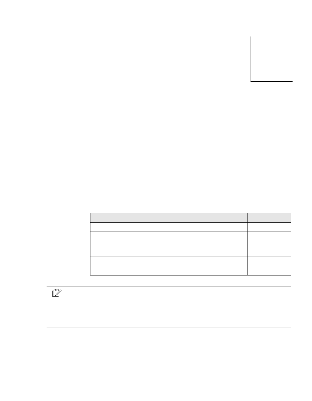
This section contains the following information about this guide:
Topic See
Content of Safety Manual page 2
Basic skills and knowledge page 3
Safety standards for Process & Equipment Under Control (PUC,
EUC)
Application design conform IEC 61131-3 page 6
The IEC 61508 and IEC 61511 standards page 7
1
page 4
Note
This guide does not contain information related to other Honeywell Experion PKS
systems and third-party controllers such as Allen-Bradley, Series 9000, TDC 3000, Data
Hiway, UDC, and so on.
For information about these systems, see the manufacturers bookset.
Safety Manager Safety Manual 1
Page 18
1 – The Safety Manual
Content of Safety Manual
The Safety Manual guide is a reference guide providing detailed information
regarding how safety aspects are met in Safety Manager. A reference guide is a
Safety Manager related guide and does not describe tasks in terms of how to
perform the task in terms of steps to follow. A reference guide can provide input
to support decisions required to achieve a certain objective.
Guide subjects
Safety Manual
• “Introduction” on page 9
• “Safety Manager architectures” on page 29
• “Design phases for an E/E/PE safety-related system” on page 45
• “Design and implementation phases of Safety Manager” on
page 53
• “Safety Manager special functions” on page 63
• “Safety Manager fault detection and response” on page 69
• “Using Safety Manager alarm markers and diagnostic inputs” on
page 109
• “Fire and gas application example” on page 117
• “Special requirements for TUV-approved applications” on
page 141
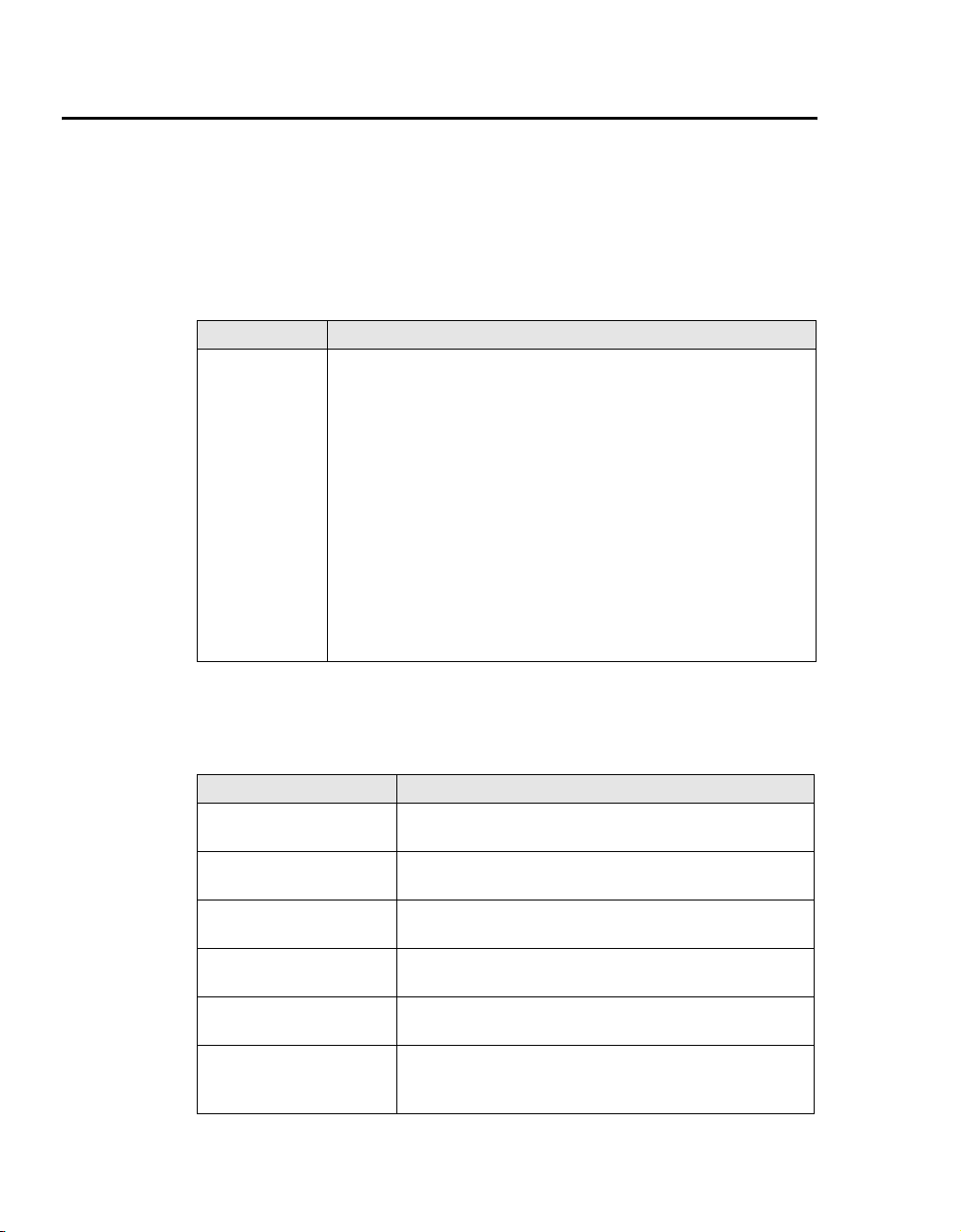
References
The following guides may be required as reference materials:
Guide Description
The Overview Guide This guide describes the general knowledge required, the
The Planning and Design
Guide
The Troubleshooting and
Maintenance Guide
The System Administration
Guide
The Hardware Reference This guide specifies the hardware components that build a
The Software Reference This guide specifies the software functions that build a
2 Release 100.3
basic functions of, and the tasks related to Safety Manager.
This guide describes the tasks related to planning and
designing a Safety Manager project.
This guide describes the tasks related to troubleshooting and
maintaining Safety Manager.
This guide describes the task related to administrating the
computer systems used in a Safety Manager project.
Safety Manager project.
Safety Manager project and contains guidelines on how to
operate them.
Page 19

Basic skills and knowledge
Before performing tasks related to Safety Manager you need to:
• Understand basic Safety Manager concepts as explained in the Overview
Guide and the Glossary.
• Have a thorough understanding of the Safety Manual.
• Have had appropriate training related to Safety Manager that certifies you for
your tasks (see the Planning and Design Guide).
Prerequisite skills
When you perform tasks related to Safety Manager, it is assumed that you have
appropriate knowledge of:
• Site procedures
• The hardware and software you are working with. These may i.e be:
computers, printers, network components, Controller and Station software.
• Microsoft Windows operating systems.
• Programmable logic controllers (PLCs).
• Applicable safety standards for Process & Equipment Under Control.
• Application design conform IEC 61131-3.
• The IEC 61508 and IEC 61511 standards.
This guide assumes that you have a basic familiarity with the process(es)
connected to the equipment under control.
Basic skills and knowledge
Training
Most of the skills mentioned above can be achieved by appropriate training. For
more information, contact your Honeywell SMS representative or see:
• http://www.honeywellsms.com or
• http://www.automationcollege.com.
Safety Manager Safety Manual 3
Page 20

1 – The Safety Manual
Safety standards for Process & Equipment Under Control (PUC, EUC)
Safety Manager is a PLC based Safety Instrumented System (SIS) performing
specific safety functions to ensure risks are kept at predefined levels.
A SIS measures, independently from the Basic Process Control System, a couple
of relevant process signals like temperature, pressure, level in a tank or the flow
through a pipe. The values of these signals are compared with the predefined safe
values, and if needed, the SIS gives an alarm or takes action. In such cases the SIS
controls the safety of the process and lowers the chance of an unsafe situation.
The logic in Safety Manager defines the response to process parameters.
In this context the following terms are explained in this section:
• Safety Integrity Level (SIL)
• Equipment Under Control (EUC)
• Process Under Control (PUC)
Safety Integrity Level (SIL)
The IEC 61508 standard specifies 4 levels of safety performance for safety
functions. These are called safety integrity levels. Safety integrity level 1 (SIL1)
is the lowest level of safety integrity, and safety integrity level 4 (SIL4) the
highest level. If the level is below SIL 1, the IEC 61508 and IEC 61511 do not
apply.
Safety Manager can be used for processes requiring a SIL1, SIL2 and SIL3.
To achieve the required safety integrity level for the E/E/PE safety-related
systems, an overall safety life cycle is adopted as the technical framework (as
defined in IEC 61508). For more information see inside the Safety Manual.
Equipment Under Control (EUC)
EUC is the equipment controlled by Safety Manager.
Safety-related systems are designed to prevent the EUC from going into a
dangerous state. Safety-related systems can broadly be divided into:
• Emergency shutdown systems.
• Fire and Gas detection and control systems.
Safety-related systems interface with the process through sensors and actuators.
The required safety integrity level may be achieved by implementing the safety
4 Release 100.3
Page 21

Safety standards for Process & Equipment Under Control (PUC, EUC)
functions in the process control system or by using separate and independent
systems dedicated to safety.
During the various phases of the safety cycle different knowledge and skills are
required with respect to EUC. For more information see inside the Safety Manual.
Process Under Control (PUC)
A Process Under Control is Equipment Under Control expanded with additional
regulations for the process (i.e. refining).
• Where EUC is concerned, the emphasis is on keeping the equipment safe.
• Where PUC is concerned, the emphasis is on keeping the process safe
(broader perspective).
Where PUC is concerned, Safety Manager monitors the process for abnormal
situations. Safety Manager is able to initiate safety actions and process alarms. An
alarm can be caused by abnormal situations in the:
• Process
• Safety loops
• Safety system itself
Safety Manager Safety Manual 5
Page 22
1 – The Safety Manual
Application design conform IEC 61131-3
The IEC 61131 standard defines, as a minimum set, the basic programming
elements, syntactic and semantic rules for the most commonly used programming
languages, including graphical languages of:
• Ladder Diagram,
• Functional Block Diagram and,
• Textual languages of Instruction List and structured Text;
For more information see the IEC web site.
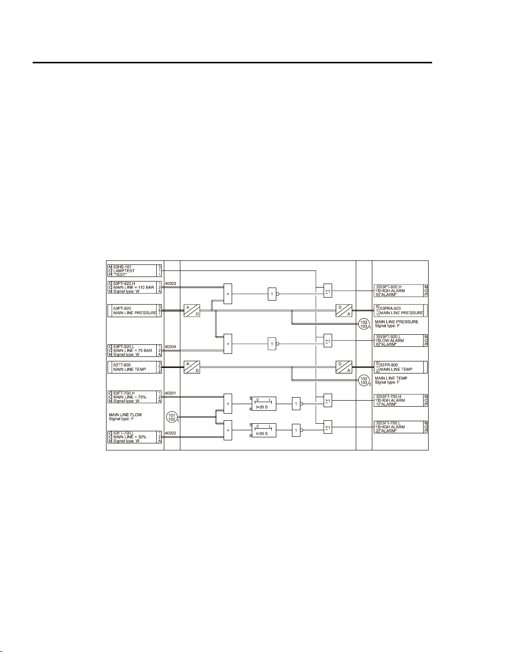
Figure 1 on page 6 shows how Safety Manager uses the graphical programming
method, based on Functional Block Diagram as defined by the IEC 61131-3.
Figure 1 Example FLD layout
6 Release 100.3
Page 23

The IEC 61508 and IEC 61511 standards
The IEC 61508 and IEC 61511 standards
SISs have been used for many years to perform safety functions e.g. in chemical,
petro-chemical and gas plants. In order for instrumentation to be effectively used
for safety functions, it is essential that the instrumentation meets certain minimum
standards and performance levels.
To define the characteristics, main concepts and required performance levels,
standards IEC 61508 and IEC 61511 have been developed. The introduction of
Safety Integrity level (SIL) is one of the results of these standards.
This brief provides a short explanation of each standard. Detailed information
regarding IEC 61508 and 61511 can be found on the IEC web site.
Tip
For more information regarding, or help on, implementing or determining, the applied
safety standards for your plant/process please contact your Honeywell affiliate. Our
Safety Consultants can help you to e.g.:
• perform a hazard risk analysis
• determine the SIL requirements
• design the Safety Instrumented System
• validate and verify the design
• train your local safety staff
IEC 61508, the standard for all safety related systems
The IEC 61508 is called “Functional safety of
electrical/electronic/programmable electronic safety-related systems”
IEC 61508 covers all safety-related systems that are electrotechnical in nature
(i.e. electromechanical systems, solid-state electronic systems and
computer-based systems).
The standard is generic and can be used directly by industry (as a “standalone”
standard) and serves as a basis for the development of sector standards (e.g. for
the machinery sector, the process sector the nuclear sector, etc.).
SIL
IEC 61508 details the design requirements for achieving the required Safety
Integrity Level (SIL).
The safety integrity requirements for each individual safety function may differ.
The safety function and SIL requirements are derived from the hazard analysis
and the risk assessment.
The higher the level of adapted safety integrity, the lower the likelihood of
dangerous failure of the SIS.
Safety Manager Safety Manual 7
Page 24

1 – The Safety Manual
This standard also addresses the safety-related sensors and final elements
regardless of the technology used.
IEC 61511, the standard for the process industry
The IEC 61511 is called “Functional safety - Safety instrumented systems for the
process industry sector”.
This standard addresses the application of SISs for the process industries. It
requires a process hazard and risk assessment to be carried out, to enable the
specification for SISs to be derived. In this standard a SIS includes all
components and subsystems necessary to carry out the safety instrumented
function from sensor(s) to final element(s).
The standard is intended to lead to a high level of consistency in underlying
principles, terminology and information within the process industries. This
should have both safety and economic benefits.
It is strongly recommended that attention is paid to the IEC 61508 as the
IEC 61511 sits within the framework of IEC 61508.
8 Release 100.3
Page 25
Introduction
The Safety Manual describes the specifications, design guidelines, and safety
aspects related to Safety Manager.
It is created to ensure that the required safety knowledge for designing,
engineering and constructing Safety Manager is transferred to the user.
This section describes the following topics:
Topic See
System overview page 10
Certification page 11
Standards compliance page 13
Definitions page 20
2
Safety Manager Safety Manual 9
Page 26

2 – Introduction
System overview
Safety Manager is a Safety Instrumented System (SIS). The SIS can be used in a
number of different basic architectures (DMR, QMR) depending on the required
availability level.
The safety of Safety Manager is obtained through its specific design for these
applications. This design includes facilities for self-testing of all Safety Manager
modules through software and specialized hardware based on a failure mode
effect analysis (FMEA) for each module. Additional software diagnostic routines
are included to guarantee proper execution of the hardware. This approach can be
classified as software diversity. These features maintain the highest level of safety
operation of Safety Manager even in the single-channel configurations. By
placing these single-channel versions in parallel, one not only gets safety but also
availability: proven availability.
Safety Manager and Safety Station from Honeywell SMS provide the means to
guarantee optimal safety and availability. To achieve these goals, it is essential
that the system is operated and maintained by authorized and qualified staff. If it
is operated by unauthorized or unqualified persons, severe injuries or loss of
production could be the result. This Safety Manual covers the applications of
Safety Manager for Safety Integrity Levels (SIL) 1 to 3 in compliance with the
international standard IEC 61508.
Tip
More overview information regarding Safety Manager can be found in the Overview
Guide.
10 Release 100.3
Page 27
Certification
The advantage of applying and complying to standards is obvious:
• International standards force companies to evaluate and develop their
• Products certified conform these international standards guarantee a certain
Since functional safety is the core of the Safety Manager design, the system has
been certified for use in safety applications all around the world. Safety Manager
has been developed specifically to comply with the IEC61508 functional safety
standards, and has been certified by TUV for use in SIL1 to SIL3 applications.
Safety Manager has also obtained certification in the United States for the UL
1998 and ANSI/ISA S84.01 standards.
For a full list of all these and other certifications see “Certification” on page 11.
Certification
Safety Manager has been certified to comply with the following standards:
Certification
products and processes according a consistent and uniform way.
degree of quality and product reliability that other products lack.
International Electronical Commission (IEC) — The
design and development of Safety Manager are compliant
with IEC 61508 (as certified by TUV).
Instrument Society of America (ISA) — Certified to
fulfill the requirements laid down in ANSI/ISA S84.01.
CE compliance — Complies with CE directives
89/336/EEC (EMC) and 73/23/EEC (Low Voltage),
89/392/EEC (Machine Safety)
European Committee for Standardization — CEN,
CENELEC
Safety Manager Safety Manual 11
Page 28
2 – Introduction
Lloyds Register of Shipping — Test specification nr 1
(LRS), 96/98/EEC (EEC Marine directive)
TUV (Germany) — Certified to fulfill the requirements
of SIL3 safety equipment as defined in the following
documents: IEC61508, IEC60664-3, EN50156, EN 54-2,
EN50178, IEC 60068, IEC 61131-2, IEC 61131-3,
IEC60204.
Canadian Standards Association (CSA) — Complies
with the requirements of the following standards:
• CSA Standard C22.2 No. 0-M982 General
Requirements – Canadian Electrical Code, Part II;
• CSA Standard C22.2 No. 142-M1987 for Process
Control Equipment.
Underwriters Laboratories (UL) — Certified to fulfill
the requirements of UL 508, UL 991, UL 1998, and
ANSI/ISA S84.01.
12 Release 100.3
Factory Mutual (FM) — Certified to fulfill the
requirements of FM 3611 and FM3600 (non-incentive
field wiring circuits for selected modules and installation
in Class 1 Div 2 environments).
Page 29

Standards compliance
This subsection lists the standards Safety Manager complies with, and gives some
background information on the relevant CE marking (EMC directive and Low
Voltage directive).
Standard Title Remarks
IEC61508
(S84.01)
DIN V 0801 (1/90)
and Amendment A
(10/94)
VDE 0116 (10/89) Electrical equipment of furnaces.
EN 54 part 2
(01/90)
EN 50081-2-1994 Electromagnetic compatibility –
EN 50082-2-1995 Electromagnetic compatibility –
IEC 61010-1-1993 Safety Requirements for Electrical
IEC 61131-2-1994 Programmable controllers. Part 2:
UL 1998 Safety-related software, first
UL 508 Industrial control equipment,
Functional safety of
electrical/electronic/
programmable electronic (E/E/PE)
safety-related systems.
Principles for computers in
safety-related systems.
(German title: Grundsätze für
Rechner in Systemen mit
Sicherheitsaufgaben)
(German title: Elektrische
Ausrüstung von
Feuerungsanlagen)
Components of automatic fire
detection systems, Introduction.
(German title: Bestandteile
automatischer
Brandmeldeanlagen)
Generic emission standard, Part 2:
Industrial environment.
Generic immunity standard, Part 2:
Industrial environment.
Equipment for Measurement,
Control and Laboratory Use, Part
1: General Requirements.
Equipment requirements and tests.
edition.
sixteenth edition.
Standards compliance
Table 1 Safety Manager compliance to standards
Microprocessor-based safety
systems.
Underwriters Laboratories.
Underwriters Laboratories.
Safety Manager Safety Manual 13
Page 30

2 – Introduction
Tab le 1 Safety Manager compliance to standards
Standard Title Remarks
UL 991 Test for safety-related controls
employing solid-state devices,
second edition.
FM3600, FM 3611
Class I, Division 2,
Groups A, B, C &
D
Class II,
Division 2,
Groups F & G
CSA C22.2 Process control equipment.
IEC 60068-1 Basic environmental testing
IEC 60068-2-1 Cold test. 0°C (32°F); 16 hours; system in
IEC 60068-2-1 Cold test. –10°C (14°F); 16 hours; system
IEC 60068-2-2 Dry heat test. up to 65°C (149°F); 16 hours;
IEC 60068-2-3 Test Ca: damp heat, steady state. 21 days at +40°C (104°F), 93%
IEC 60068-2-3 Test Ca: damp heat, steady state. 96 hours at +40°C (104°F), 93%
IEC 60068-2-14 Test Na: change of temperature –
Electrical equipment for use in
• Class I, Division 2,
• Class II, Division 2, and
• Class III, Division 1 and 2,
hazardous locations.
Industrial products.
procedures.
withstand test.
Underwriters Laboratories.
Factory Mutual Research.
Applies to the field wiring
circuits of the following
modules:
SDI-1624, SAI-0410,
SAI-1620m, SDIL-1608 and
SAO-0220m, and installation of
the Controller in these
environments.
Canadian Standards Association
No. 142 (R1993).
operation; reduced power supply
voltage:
(–15%): U=20.4 Vdc or
(–10%): U=198 Vac.
in operation.
system in operation; increased
power supply voltage:
(+15%): U=27.6 Vdc or
(+10%): U=242 Vac.
relative humidity; function test
after cooling.
relative humidity; system in
operation.
–25°C—+55°C (–13°F—
+131°F), 12 hours, 95% relative
humidity, recovery time: max. 2
hours.
14 Release 100.3
Page 31

Table 1 Safety Manager compliance to standards
Standard Title Remarks
IEC 60068-2-30 Test Db variant 2: cyclic damp
heat test.
IEC 60068-2-6 Environmental testing – Part 2:
Tests – Test.
Fc: vibration (sinusoidal).
IEC 60068-2-27 Environmental testing – Part 2:
Tests – Test.
Ea: shock.
+25°C—+55°C (+77°F—
+131°F), 48 hours, 80-100%
relative humidity, recovery time:
1—2 hours.
Excitation: sine-shaped with
sliding frequency;
Frequency range: 10—150 Hz.
Loads:
• 10—57 Hz; 0.075 mm.
• 57—150 Hz; 1 G.
Duration: 10 cycles (20 sweeps)
per axis.
No. of axes: 3 (x, y, z).
Traverse rate: 1 oct/min in
operation.
Half sine shock.
2 shocks per 3 axes (6 in total).
Maximum acceleration: 15 G.
Shock duration: 11 ms.
Safety Manager in operation.
Standards compliance
Safety Manager Safety Manual 15
Page 32

2 – Introduction
EU Standards
This section explains the major EU standards that apply to Safety Manager.
These standards are:
Topic See
CE marking page 16
EMC directive (89/336/EEC) page 17
Low voltage directive (73/23/EEC) page 18
Machine safety directive (89/392/EEC)) page 18
CE marking
The CE mark (see Figure 2 on page 16) is a compliance symbol, which indicates
that a product meets the requirements of the EU directives that apply to that
product. CE (Conformité Européenne) marking is a legal requirement for selling
products in the European Union.
EU directives documentation is issued on the authority of the Council of the
European Union. It contains requirements and regulations for certain categories
of products or problem areas. The directives apply not only to member countries
of the European Union but also to the whole European Economic Area (EEA).
The European directives have the following key objectives:
• Free movement of goods within the EU/EEA geographical regions through
harmonization of standards and elimination of trade barriers.
• Safety of persons, their property and of animals.
• Protection of the environment.
For control products like Safety Manager, a number of EU directives apply.
Safety Manager is compliant with: the Electromagnetic Compatibility (EMC)
Directive (89/336/EEC), the Low Voltage Directive (73/23/EEC), Marine
Directive (96/98/EEC) and Machine Safety Directive (89/392/EEC). Some are
16 Release 100.3
Figure 2 CE mark
Page 33

discussed in more detail below. An item of equipment may only display the CE
mark when the equipment satisfies all relevant directives.
EMC directive (89/336/EEC)
One of the EU directives Safety Manager complies with is the EMC directive, or
Council Directive 89/336/EEC of 3 May 1989 on the approximation of the laws of
the Member States relating to electromagnetic compatibility as it is officially
called. It “applies to apparatus liable to cause electromagnetic disturbance or the
performance of which is liable to be affected by such disturbance” (Article 2).
The EMC directive defines protection requirements and inspection procedures
relating to electromagnetic compatibility for a wide range of electric and
electronic items.
Within the context of the EMC directive, ‘apparatus’ means all electrical and
electronic appliances together with equipment and installations containing
electrical and/or electronic components. ‘Electromagnetic disturbance’ means
any electromagnetic phenomenon which may degrade the performance of a
device, unit of equipment or system. An electromagnetic disturbance may be
electromagnetic noise, an unwanted signal or a change in the propagation medium
itself.
‘Electromagnetic compatibility’ is the ability of a device, unit of equipment or
system to function satisfactorily in its electromagnetic environment without
introducing intolerable electromagnetic disturbances to anything in that
environment.
There are two sides to electromagnetic compatibility: emission and immunity.
These two essential requirements are set forth in Article 4, which states that an
apparatus must be constructed so that:
1. The generated electromagnetic disturbance does not exceed a level allowing
radio and telecommunications equipment and other apparatus to operate as
intended.
2. The apparatus has an adequate level of intrinsic immunity of electromagnetic
disturbance to enable it to operate as intended.
The EMC directive was originally published in the Official Journal of the
European Communities on May 23, 1989. As of January 1, 1996 compliance with
the EMC directive is mandatory (a legal requirement). All electronic products
may now only be marketed in the European Union if they meet the requirements
laid down in the EMC directive. This also applies to Safety Manager cabinets.
EU Standards
Safety Manager Safety Manual 17
Page 34

2 – Introduction
Low voltage directive (73/23/EEC)
Safety Manager also complies with the low voltage directive, or Council
Directive 73/23/EEC of 19 February 1973 on the harmonization of the laws of the
Member States relating to electrical equipment designed for use within certain
voltage limits as it is officially called. It states that “electrical equipment may be
placed on the market only if, having been constructed in accordance with good
engineering practice in safety matters in force in the Community, it does not
endanger the safety of persons, domestic animals or property when properly
installed and maintained and used in applications for which it was made” (Article
2).
The low voltage directive defines a number of principal safety objectives that
electrical equipment must meet in order to be considered “safe”.
Within the context of the low voltage directive, ‘electrical equipment’ means any
equipment designed for use with a voltage rating of between 50 and 1,000 V for
alternating current (AC) and between 75 and 1,500 V for direct current (DC).
The low voltage directive was originally published in the Official Journal of the
European Communities on March 26, 1973. It was amended by Council Directive
93/68/EEC. As of January 1, 1997 compliance with the low voltage directive is
mandatory (a legal requirement). All electronic products may now only be
marketed in the European Union if they meet the requirements laid down in the
low voltage directive. This also applies to Safety Manager cabinets.
Machine safety directive (89/392/EEC))
The directive holds the requirements for machinery safety in every country within
the European Economic Area (EEA). The Directive applies to all machinery and
to safety components. A machine is defined as “an assembly of linked parts or
components, at least one of which moves…”
Machinery meeting the requirements of the Directive is required to have the CE
symbol clearly affixed to indicate compliance. An item of equipment may only
display the CE mark when the equipment satisfies all relevant directives.
The Directive requires the machines manufacturer to produce a Technical File
containing documentary evidence that the machinery complies with the directive.
The Directive also effectively allows a period of grace in which the file can be
assembled after it has been requested by the authorities.
The Directive gives a comprehensive list of the potential hazards (annex I) which
may arise from the design and operation of machinery, and gives general
instructions on what hazards must be avoided. Detailed requirements are laid out
in a series of safety standards.
18 Release 100.3
Page 35

EU Standards
Because so many standards are required to cover the full range of machines
within the scope of the Directive, the European standards bodies devised a
hierarchy which can be applied in every situation:
• ‘Type A’ are the most basic standards set out the requirements for the safety of
machines only in the most general terms: part 2 of EN292 is essentially a
reproduction of annex 1 of the Machinery Directive.
• ‘Type B’ standards deal with more specific issues: design of emergency stops
(EN418); prevention of unexpected start-up (EN1037); pneumatic systems
(EN983); temperature of touchable surfaces (EN563) and many others.
• ‘Type C’ standards deal with specific classes of machinery: for example,
EN1012 deals with safety of compressors and vacuum pumps; EN 792 deals
with pneumatic hand tools.
Safety Manager Safety Manual 19
Page 36

2 – Introduction
Definitions
Dangerous failure
Error
This section provides a list of essential safety terms that apply to Safety Manager.
All definitions have been taken from IEC 61508-4, published in 2000.
Failure which has the potential to put the safety-related system in a hazardous or
fail-to-function state.
Note
Whether or not the potential is realized may depend on the channel architecture of the
system; in systems with multiple channels to improve safety, a dangerous hardware
failure is less likely to lead to the overall dangerous or fail-to-function state.
Discrepancy between a computed, observed or measured value or condition and
the true, specified or theoretically correct value or condition.
EUC risk
Failure
Risk arising from the EUC or its interaction with the EUC control system.
The termination of the ability of a functional unit to perform a required function.
Note
• The definition in IEV 191-04-01 is the same, with additional notes.
• See Figure 3 on page 21 for the relationship between faults and failures, both in
IEC 61508 and IEV 191.
• Performance of required functions necessarily excludes certain behavior, and some
functions may be specified in terms of behavior to be avoided. The occurrence of such
behavior is a failure.
• Failures are either random (in hardware) or systematic (in hardware or software).
20 Release 100.3
Page 37

Fault
Functional safety
Definitions
Abnormal condition that may cause a reduction in, or loss of, the capability of a
functional unit to perform a required function.
Note
IEV 191-05-01 defines “fault” as a state characterized by the inability to perform a
required function, excluding the inability during preventative maintenance or other
planned actions, or due to lack of external resources.
Part of the overall safety relating to the EUC and the EUC control system which
depends on the correct functioning of the E/E/PE safety-related systems, other
technology safety-related systems and external risk reduction facilities.
Figure 3 Failure model
L (i-1) FU
L (i FU
L (i+1) FU L (i+1) FU
L (i+1) FUL (i+1) FU
L= level, i=1,2,3, etc.; FU=Functional Unit
A) Configuration of a Functional Unit
Level(i) Level(i-1)
failure
fault
C) IEC 61508's and ISO/IEC 2382-14's view
L (i FU
L (i+1) FU L (i+1) FU
"Entity X"
failure
fault
Level(i) Level(i-1)
"F" state
"Entity X"
L (i+1) FUL (i+1) FU
"F" state
failure
cause
B) Generalized view
Level(i) Level(i-1)
fault
failure
failure cause
"Entity X"
D) IEC 50(191)'s view
failure
cause
fault
failure
failure cause
Safety Manager Safety Manual 21
Page 38

2 – Introduction
Notes for Figure 3 on page 21
• As shown in A), a functional unit can be viewed as a hierarchical composition of
multiple levels, each of which can in turn be called a functional unit. In level (i), a
“cause” may manifest itself as an error (a deviation from the correct value or state)
within this level (i) functional unit, and, if not corrected or circumvented, may cause a
failure of this functional unit, as a result of which it falls into an “F” state where it is no
longer able to perform a required function (see B)). This “F” state of the level (i)
functional unit may in turn manifest itself as an error in the level (i-1) functional unit
and, if not corrected or circumvented, may cause a failure of this level (i-1) functional
unit.
• In this cause and effect chain the same thing (“Entity X”) can be viewed as a state (“F”
state) of the level (i) functional unit into which it has fallen as a result of its failure, and
also as the cause of the level (i-1) functional unit. This “Entity X” combines the
concept of “fault” in IEC 61508 and ISO/IEC 2382-14, which emphasizes its cause
aspect as illustrated in C), and that of “fault” in IEC 50(191), which emphasizes its
state aspect as illustrated in D). The “F” state is called fault in IEC 50(191), whereas it
is not defined in IEC 61508 and ISO/IEC 2382-14.
• In some cases, a failure may be caused by an external event such as lightning or
electrostatic noise, rather than by an internal fault. Likewise, a fault (in both
vocabularies) may exist without a prior failure. An example of such a fault is a design
fault.
Functional safety assessment
Investigation, based on evidence, to judge the functional safety achieved by one
or more E/E/PE safety-related systems, other technology safety-related systems
or external risk reduction facilities.
Human error
Mistake.
Human action or inaction that produces an unintended result.
Hardware safety integrity
Part of the safety integrity of the safety related systems relating to random
hardware failures in a dangerous mode of failure.
Note
The term relates to failures in a dangerous mode. That is, those failures of a safety-related
system that would impair its safety integrity. The two parameters that are relevant in this
context are the overall dangerous failure rate and the probability of failure to operate on
demand. The former reliability parameter is used when it is necessary to maintain
continuous control in order to maintain safety, the latter reliability parameter is used in the
context of safety-related protection systems.
22 Release 100.3
Page 39

Mode of operation
Way in which a safety-related system is intended to be used, with respect to the
frequency of demands made upon it in relation to the proof check frequency,
which may be either:
• Low demand mode - where the frequency of demands for operation made on
a safety-related system is not significantly greater than the proof check
frequency; or
• High demand or continuous mode - where the frequency of demands for
operation made on a safety-related system is significantly greater than the
proof check frequency.
Note
Typically for low demand mode, the frequency of demands on the safety-related system is
the same order of magnitude as the proof test frequency (i.e. months to years where the
proof test interval is a year). While typically for high demand or continuous mode, the
frequency of demands on the safety-related system is hundreds of times the proof test
frequency (i.e. minutes to hours where the proof test interval is a month).
Programmable electronic system (PES)
System for control, protection or monitoring based on one or more programmable
electronic devices, including all elements of the system such as power supplies,
sensors and other input devices, data highways and other communication paths,
and actuators and other output devices (see Figure 4 on page 24).
Definitions
Note
The structure of a PES is shown in Programmable electronic system (PES): structure and
terminology A). Programmable electronic system (PES): structure and terminology B)
illustrates the way in which a PES is represented in IEC 61508, with the programmable
electronics shown as a unit distinct from sensors and actuators on the EUC and their
interfaces, but the programmable electronics could exist at several places in the PES.
Programmable electronic system (PES): structure and terminology C) illustrates a PES
with two discrete units of programmable electronics. Programmable electronic system
(PES): structure and terminology D) illustrates a PES with dual programmable electronics
(i.e. two channel), but with a single sensor and a single actuator.
Safety Manager Safety Manual 23
Page 40

2 – Introduction
Figure 4 Programmable electronic system (PES): structure and terminology
Risk
Safe failure
Output interfaces
D-A converters
Output devices/final elements
(eg actuators)
PE
2
D) Single PES with dual program-
mable electronic devices but with
shared sensors and final elements (ie
one PES comprised of two channels
of programmable electronics)
PE
PE
1
2
PE
Input interfaces
A-D converters
Input devices
(eg sensors)
Extend
of PES
B) Single PES with single program-
mable electronic device (ie one PES
comprised of a single channel of
programmable electronics)
Communications
Programmable
electronics
(see note)
A) Basic PES structure
PE
1
C) Single PES with dual program-
mable electronic devices linked in a
serial manner (eg intelligent sensor
and programmable controller)
Combination of the probability of occurrence of harm and the severity of that
harm.
Failure which does not have the potential to put the safety-related system in a
hazardous or fail-to-function state.
Note
Whether or not the potential is realized may depend on the channel architecture of the
system; in systems with multiple channels to improve safety, a safe hardware failure is
less likely to result in an erroneous shutdown.
Safety
Freedom from unacceptable risk.
Safety integrity level (SIL)
Discrete level (one out of a possible four) for specifying the safety integrity
requirements of the safety functions to be allocated to the E/E/PE safety-related
24 Release 100.3
Page 41

Definitions
systems, where safety integrity level 4 has the highest level of safety integrity and
safety integrity level 1 has the lowest.
Note
• The target failure measures for the safety integrity levels are specified in Safety
integrity levels: target failure measures for a safety function, allocated to the E/E/PE
Safety Related System operating in low demand mode of operation and Safety
integrity levels: target failure measures for a safety function, allocated to the E/E/PE
Safety Related System operating in high demand or continuous mode of operation.
Table 2 Safety integrity levels: target failure measures for a safety function, allocated to the E/E/PE
Safety Related System operating in low demand mode of operation
Safety integrity level Low demand mode of operation
(average probability of failure to perform its design function
on demand)
4 ≥ 10
-5
3 ≥ 10-4 to < 10
2 ≥ 10-3 to < 10
1 ≥ 10-2 to < 10
NOTE: see notes below for details on interpreting this table.
to < 10
-4
-3
-2
-1
Table 3 Safety integrity levels: target failure measures for a safety function, allocated to the E/E/PE
Safety Related System operating in high demand or continuous mode of operation
Safety integrity level High demand or continuous mode of operation (probability
of a dangerous failure per hour)
4 ≥ 10
-9
3 ≥ 10-8 to < 10
2 ≥ 10-7 to < 10
1 ≥ 10-6 to < 10
to < 10
-8
-7
-6
-5
NOTE: see notes below for details on interpreting this table.
Safety Manager Safety Manual 25
Page 42

2 – Introduction
Note
1. The parameter in Safety integrity levels: target failure measures for a safety function,
allocated to the E/E/PE Safety Related System operating in high demand or continuous
mode of operation, probability of a dangerous failure per hour, is sometimes referred
to as the frequency of dangerous failures, or dangerous failure rate, in units of
dangerous failures per hour.
2. This document sets a lower limit on the target failure measures, in a dangerous mode
of failure, than can be claimed. These are specified as the lower limits for safety
integrity level 4 (that is an average probability of failure of 10
function on demand, or a probability of a dangerous failure of 10
possible to achieve designs of safety-related systems with lower values for the target
failure measures for non-complex systems, but it is considered that the figures in the
table represent the limit of what can be achieved for relatively complex systems (for
example programmable electronic safety-related systems) at the present time.
3. The target failure measures that can be claimed when two or more E/E/PE
safety-related systems are used may be better than those indicated in Safety integrity
levels: target failure measures for a safety function, allocated to the E/E/PE Safety
Related System operating in low demand mode of operation and Safety integrity
levels: target failure measures for a safety function, allocated to the E/E/PE Safety
Related System operating in high demand or continuous mode of operation providing
that adequate levels of independence are achieved.
4. It is important to note that the failure measures for safety integrity levels 1, 2, 3 and 4
are target failure measures. It is accepted that only with respect to the hardware safety
integrity will it be possible to quantify and apply reliability prediction techniques in
assessing whether the target failure measures have been met. Qualitative techniques
and judgements have to be made with respect to the precautions necessary to meet the
target failure measures with respect to the systematic safety integrity.
5. The safety integrity requirements for each safety function shall be qualified to indicate
whether each target safety integrity parameter is either:
• the average probability of failure to perform its design function on demand (for a low
demand mode of operation); or
• the probability of a dangerous failure per hour (for a high demand or continuous mode
of operation).
-5
to perform its design
-9
per hour). It may be
Safety life cycle
Necessary activities involved in the implementation of safety-related systems,
occurring during a period of time that starts at the concept phase of a project and
finishes when all of the E/E/PE safety-related systems, other technology
safety-related systems and external risk reduction facilities are no longer
available for use.
Safety-related system
Designated system that both:
• implements the required safety functions necessary to achieve or maintain a
safe state for the EUC, and
26 Release 100.3
Page 43

Definitions
• is intended to achieve, on its own or with other E/E/PE safety-related systems,
other technology safety-related systems or external risk reduction facilities,
the necessary safety integrity for the required safety functions.
Note
1. The term refers to those systems, designated as safety-related systems, that are
intended to achieve, together with the external risk reduction facilities, the necessary
risk reduction in order to meet the required tolerable risk.
2. The safety-related systems are designed to prevent the EUC from going into a
dangerous state by taking appropriate action on receipt of commands. The failure of a
safety-related system would be included in the events leading to the identified hazard
or hazards. Although there may be other systems having safety functions, it is the
safety-related systems that have been designated to achieve, in their own right, the
required tolerable risk. Safety-related systems can broadly be divided into
safety-related control systems and safety-related protection systems, and have two
modes of operation.
3. Safety-related systems may be an integral part of the EUC control system or may
interface with the EUC by sensors and/or actuators. That is, the required safety
integrity level may be achieved by implementing the safety functions in the EUC
control system (and possibly by additional separate and independent systems as well)
or the safety functions may be implemented by separate and independent systems
dedicated to safety.
4. A safety-related system may:
• be designed to prevent the hazardous event (that is if the safety-related systems
perform their safety functions then no hazard arises). The key factor here is the
ensuring that the safety-related systems perform their functions with the degree of
certainty required (for example, for the specified functions, that the average
probability of failure should not be greater than 10
demand).
• be designed to mitigate the effects of the hazardous event, thereby reducing the risk by
reducing the consequences. As for the first item in this list, the probability of failure on
demand for the specified functions (or other appropriate statistical measure) should be
met.
• be designed to achieve a combination of both kinds of systems.
5. A person can be part of a safety-related system. For example, a person could receive
information from a programmable electronic device and perform a safety task based
on this information, or perform a safety task through a programmable electronic
device.
6. The term includes all the hardware, software and supporting services (for example
power supplies) necessary to carry out the specified safety function (sensors, other
input devices, final elements (actuators) and other output devices are therefore
included in the safety-related system).
7. A safety-related system may be based on a wide range of technologies including
electrical, electronic, programmable electronic, hydraulic and pneumatic.
-4
to perform its design function on
Safety Manager Safety Manual 27
Page 44

2 – Introduction
Systematic safety integrity
Part of the safety integrity of safety-related systems relating to systematic failures
in a dangerous mode of failure.
Note
Systematic safety integrity cannot usually be quantified (as distinct from hardware safety
integrity which usually can).
Validation
Confirmation by examination and provision of objective evidence that the
particular requirements for a specific intended use are fulfilled.
28 Release 100.3
Page 45

Safety Manager architectures
To optimize Safety Manager for multiple processes (i.e. batch processing and
continues processing), the system can be supplied in a number of architectures,
each with its own characteristics and typical applications.
This section provides information on the Safety Manager architectures. It covers
the following topics:
Topic See
Safety Manager basic architectures page 30
Dual Modular Redundant (DMR) architecture page 30
Quadruple Modular Redundant (QMR) architecture page 31
To optimize the choice for a certain system architecture, the availability level is
stated next to the type of architecture.
3
Topic Availability level See
System architectures: page 32
• Non-redundant Controller and non-redundant IO
• Redundant Controller and non-redundant IO
• Redundant Controller and redundant IO
• Redundant Controller with redundant and
non-redundant IO
normal page 32
increased page 33
optimal page 35
optimal page 37
Safety Manager Safety Manual 29
Page 46

3 – Safety Manager architectures
Safety Manager basic architectures
Safety Manager can be configured for a number of architectures, each with its
own characteristics and typical applications. Table 4 on page 30 provides an
overview of the available architectures.
Tab le 4 Safety Manager architectures
Controller
configuration
Non-redundant
(DMR, see page 30)
Redundant
(QMR, see page 31)
IO configuration Remarks
Non-redundant, see page 32 DMR architecture;
• Non-redundant, see page 33
• Redundant, see page 35
• Redundant and non-redundant,
see page 37
DMR = Dual Modular Redundant
QMR = Quadruple Modular Redundant
All Safety Manager architectures can be used for safety applications. The
preferred architecture depends on the availability requirements.
Dual Modular Redundant (DMR) architecture
Typical applications of a DMR architecture are:
• Burner Management System
• Batch processing
• Machine safety
The Dual Modular Redundant (DMR) architecture provides 1oo2 voting in a
non-redundant system. The DMR architecture with 1oo2 voting is based on
dual-processor technology, and is characterized by a high level of self tests,
diagnostics and fault tolerance.
The DMR architecture is realized with a non-redundant Controller. A
non-redundant architecture contains only one QPP (see Figure 5 on page 31),
which contains a redundant processor with 1oo2 voting between the processors
and memory.
Applications up to SIL3
QMR architecture;
Applications up to SIL3
30 Release 100.3
Page 47

Figure 5 Functional diagram: DMR architecture
QPP Control Processor
Sensor
xx
yyy
SD
Input
Module
Input Interfaces Output Interfaces
Watchdog
Processor
Processor
In IO configurations, each path is primarily controlled by the Control Processor
and an independent switch (Secondary Means of De-energization, SMOD) which
is controlled by an independent watchdog.
Quadruple Modular Redundant (QMR) architecture
Safety Manager basic architectures
SMOD
Output
Module
Final Element
Typical applications of a QMR architecture are:
• process safeguarding applications for which continues operation is essential.
The Quadruple Modular Redundant (QMR) architecture is based on 2oo4D
voting, dual-processor technology in each QPP. This means that it is characterized
by a ultimate level of self diagnostics and fault tolerance.
The QMR architecture is realized with a redundant Controller. This redundant
architecture contains two QPPs (see Figure 6 on page 32), which results in
quadruple redundancy making it dual fault tolerant for safety.
The 2oo4D voting is realized by combining 1oo2 voting of both CPUs and
memory in each QPP, and 1oo2D voting between the two QPPs. Voting takes
place on two levels: on a module level and between the QPPs.
Safety Manager Safety Manual 31
Page 48

3 – Safety Manager architectures
SD
Figure 6 Functional diagram: QMR architecture
QPP Control Processor 1
Watchdog
SMOD
Output
Module
SMOD
Output
Module
Output Interfaces
Quad
Vot er
Final Element
Sensor
xx
yyy
Input Interfaces
Input
Module
Input
Module
Processor
Processor
Processor
Processor
Watchdog
QPP Control Processor 2
In redundant IO configurations, each path is controlled by one of the Control
Processors and an independent switch (Secondary Means of De-energization,
SMOD), which is controlled by the diagnostic software and an independent
watchdog.
Furthermore, each Control Processor is able to switch off the output channels of
the other Control Processor.
System architectures
Non-redundant Controller and non-redundant IO
This Safety Manager architecture has a non-redundant Controller and
non-redundant input and output (IO) modules (see Figure 8 on page 33 and Figure
7 on page 33).
The IO modules are controlled via the IO bus drivers (located in the QPP) and the
IO Bus, which can control up to 8 IO chassis per cabinet. Each IO chassis is
controlled via the IO Extender. There is no redundancy except for those modules
with built-in redundancy (QPP, memory and watchdog).
This architecture can be applied up to SIL3.
32 Release 100.3
Page 49

Sensor
xx
yyy
Safety Manager basic architectures
Figure 7 Functional diagram: non-redundant Controller, non-redundant IO
QPP Control Processor
SD
Input
Module
Watchdog
Processor
Processor
SMOD
Output
Module
Input Interfaces
Figure 8 Non-redundant Controller, non-redundant IO configuration
System Bus
QPP
COM
COM
Control Processor
I/O Chassis 1
SDI SDO SDI SDO
Redundant Controller and non-redundant IO
This Safety Manager architecture has a redundant Controller and non-redundant
input and output (IO) modules (see Figure 10 on page 34 and Figure 9 on
page 34).
The IO modules are controlled via the IO bus drivers (located in the QPP) and the
IO Bus, which can control up to 8 IO chassis per cabinet. Each IO chassis is
controlled via the IO Extender.
This architecture can be applied up to SIL3.
PSU
21
BKM
I/O-Bus
Output Interfaces
21
I/O
Extender
Final Element
s
u
B
O
/
I
Safety Manager Safety Manual 33
Page 50

3 – Safety Manager architectures
u
s
Interaction between Control Processors
Both Control Processors run in parallel, meaning that they simultaneously read
input states and write output states. Via the redundant link both Control
Processors continuously inform each other about the achieved IO states,
application states. The redundant link is used to synchronize actions and compare
results. For more information see “Quadruple Modular Redundant (QMR)
architecture” on page 31.
A redundant Controller is single fault tolerant with respect to availability.
SD
Figure 9 Functional diagram: redundant Controller, non-redundant IO
QPP Control Processor 1
Watchdog
Processor
Processor
Sensor
xx
yyy
Input Interfaces Output Interfaces
Input
Module
Processor
Processor
Watchdog
QPP Control Processor 2
SMOD
Output
Module
Figure 10 Redundant Controller, non-redundant IO configuration
System Bus
QPP
COM
Control Processor 1
I/O Chassis n+1
COM
SDI SDO SDI SDO
PSU
21
BKM
I/O-Bus
QPP
COM
COM
Control Processor 2
Final Element
PSU
21
I/O
Extender
B
O
/
I
34 Release 100.3
Page 51

Redundant Controller and redundant IO
This Safety Manager architecture has a redundant Controller and redundant input
and output (IO) modules (OR function outputs) (see Figure 12 on page 36 and
Figure 11 on page 36).
The IO modules are controlled via the IO bus drivers (located in the QPP) and the
IO Bus, which can control up to 8 IO chassis per cabinet. Each IO chassis is
controlled via the IO Extender. The processor and IO are fully redundant, which
allows continuous operation and smooth (zero-delay) transfer of the control in
case of a Control Processor or IO failure.
This architecture can be applied up to SIL3.
Interaction between Control Processors
Both Control Processors run in parallel, meaning that they simultaneously read
input states and write output states. Via the redundant link both Control
Processors continuously inform each other about the achieved IO states,
application states. The redundant link is used to synchronize actions and compare
results. For more information see “Quadruple Modular Redundant (QMR)
architecture” on page 31.
Interaction between redundant IO
Both IO modules reside next to each other in the same IO chassis. On the
backplane they are wired parallel.
• In principle, when a fault is detected in an input channel, this channel is
deactivated by its corresponding Control Processor. The correct value is
obtained from the IO module connected to the other Control Processor via the
redundant internal link before the application cycle is started.
• In principle, when a fault is detected in an output channel, this channel is
de-energized by the SMOD (see “Secondary means” on page 25 for details).
The correct value is driven into the field by the other Control Processor, but
not after both Control Processors have agreed on its value via the redundant
internal link.
For more information see “Fault detection and response” on page 23.
Safety Manager basic architectures
Safety Manager Safety Manual 35
Page 52

3 – Safety Manager architectures
SD
Figure 11 Functional diagram: redundant Controller, redundant IO
QPP Control Processor 1
Watchdog
Sensor
xx
yyy
Input Interfaces
QPP
SMOD
Output
Module
SMOD
Output
Module
Output Interfaces
Input
Module
Input
Module
Processor
Processor
Processor
Processor
Watchdog
QPP Control Processor 2
Figure 12 Redundant Controller, redundant IO configuration
System Bus
COM
COM
PSU
COM
Control Processor 1
BKM
QPP
Control Processor 2
COM
Quad
Voter
Final Element
PSU
I/O Chassis 1
I/O Chassis n
36 Release 100.3
SDI SDI
SDI SDI
I/O-Bus
2
SDO SDO
SDO SDO
2011718
21
I/O
I/O
EXTENDER
EXTENDER
I/O
I/O
EXTENDER
EXTENDER
s
u
B
O
/
I
Page 53

Redundant Controller with redundant and non-redundant IO
This Safety Manager architecture has a redundant Controller and redundant input
and output (IO) modules (OR function outputs) combined with non-redundant
input and output modules (see Figure 13 on page 37 and Figure 14 on page 38).
This architecture can be applied up to SIL3.
This architecture is a mix of the described:
• “Redundant Controller and non-redundant IO” on page 33 and
• “Redundant Controller and redundant IO” on page 35.
Figure 13 Redundant Controller with redundant and non-redundant IO configuration
Safety Manager basic architectures
System Bus
Selective watchdog
QPP
COM
Control Processor 1
I/O Chassis 1
I/O Chassis n
I/O Chassis n+1
COM
2
SDI SDI
SDI SDI
SDI SDO
PSU
21
BKM
I/O-Bus
QPP
SDO SDO
SDO SDO
SDI SDO
COM
COM
Control Processor 2
2011718
I/O
EXTENDER
I/O
EXTENDER
21
I/O
EXTENDER
I/O
EXTENDER
21
I/O
Extender
PSU
In a system with combined redundant and non redundant IO 3 watchdog lines are
active:
• WD1
This is the Watchdog line dedicated for Control Processor 1.
- De-energizes upon a safety related fault in Control Processor 1 or an
output module of Control Processor 1.
- When de-energized, Control Processor 1 and the related outputs are halted.
s
u
B
O
/
I
Safety Manager Safety Manual 37
Page 54

3 – Safety Manager architectures
•WD2
This is the Watchdog line dedicated for Control Processor 2.
- De-energizes upon a safety related fault in Control Processor 2 or an
output module of Control Processor 2.
- When de-energized, Control Processor 2 and the related outputs are halted.
• WD3
This is the combined watchdog line, controlled by both Control Processors.
- De-energizes upon a safety related fault in a non redundant output.
- When de-energized, the non-redundant outputs are de-energized, but the
redundant outputs and the Control Processors remain operational.
Figure 14 Functional diagram: redundant Controller with redundant and non-redundant IO
SD
QPP Control Processor 1
Watchdog
Sensor
xx
yyy
Sensor
xx
yyy
Input Interfaces
Input
Module
Input
Module
Input
Module
Processor
Processor
Processor
Processor
Watchdog
QPP Control Processor 2
SMOD
Output
Module
SMOD
Output
Module
SMOD
Output
Module
Output Interfaces
Quad
Vote r
Final Element
Final Element
38 Release 100.3
Page 55

Overall safety life cycle
To deal in a systematic manner with all the activities necessary to achieve the
required safety integrity level for the E/E/PE safety-related systems, an overall
safety life cycle is adopted as the technical framework (as defined in IEC 61508)
(see Figure 15 on page 39).
Overall safety life cycle
Figure 15 Overall safety life cycle
Safety Manager Safety Manual 39
Page 56

3 – Safety Manager architectures
Note
• Activities relating to verification, management of functional safety and functional
safety assessment are not shown for reasons of clarity. These activities are relevant to
all overall, E/E/PES and software safety life cycle phases.
• The phases represented by boxes 10 and 11 are outside the scope of this standard.
• Parts 2 and 3 deal with box 9 (realization) but they also deal, where relevant, with the
programmable electronic (hardware and software) aspects of boxes 13, 14 and 15.
The overall safety life cycle encompasses the following risk reduction measures:
• E/E/PE safety-related systems
• Other technology safety-related systems
• External risk reduction facilities
The portion of the overall safety life cycle dealing with E/E/PE safety-related
systems is expanded and shown in Figure 16 on page 40. The software safety life
cycle is shown in Figure 17 on page 41. The relationship of the overall safety life
cycle to the E/E/PES and software safety life cycles for safety-related systems is
shown in Figure 18 on page 41.
Figure 16 E/E/PES safety life cycle (in realization phase)
40 Release 100.3
Page 57

Overall safety life cycle
Figure 17 Software safety life cycle (in realization phase)
Figure 18 Relationship of overall safety life cycle to E/E/PES and software safety life cycles
The overall, E/E/PES and software safety life cycle figures (Figure 15 on page 39,
Figure 16 on page 40 and Figure 17 on page 41) are simplified views of the
reality and as such do not show all the iterations relating to specific phases or
between phases. The iterative process, however, is an essential and vital part of
development through the overall, E/E/PES and software safety life cycles.
Safety Manager Safety Manual 41
Page 58

3 – Safety Manager architectures
Objectives
Table 5 on page 42 indicates the objectives to be achieved for all phases of the
overall safety life cycle (Figure 16 on page 40).
Phase Objective Overall
Concept
Overall scope
definition
Hazard and risk
analysis
Overall safety
requirements
Safety requirements
allocation
Table 5 Overall safety life cycle overview
• To develop a level of understanding of the EUC and
its environment (physical, legislative etc.) sufficient
to enable the other safety life cycle activities to be
satisfactorily carried out.
• To determine the boundary of the EUC and the EUC
control system.
• To define the scope of the hazard and risk analysis
(for example process hazards, environmental
hazards, etc.).
• To identify the hazards and hazardous events of the
EUC and the EUC control system (in all modes of
operation), for all reasonably foreseeable
circumstances including fault conditions and misuse.
• To identify the event sequences leading to the
hazardous events identified.
• To determine the EUC risks associated with the
hazardous events identified.
• To develop the specification for the overall safety
requirements to achieve the required functional
safety. These specifications contain the safety
functions requirements and safety integrity
requirements, for the E/E/PE safety-related systems,
other technology safety-related systems and external
risk reduction facilities.
• To allocate the safety functions to the designated
E/E/PE safety-related systems, other technology
safety-related systems and external risk reduction
facilities.
• To allocate a safety integrity level to each safety
function.
safety
life cycle
box
number
1
2
3
4
5
42 Release 100.3
Page 59

Overall safety life cycle
Tab le 5 Overall safety life cycle overview (continued)
Phase Objective Overall
safety
life cycle
box
number
Overall operation and
maintenance
planning
Overall safety
validation planning
Overall installation
and commissioning
planning
E/E/PE
safety-related
systems: realization
Other technology
safety-related
systems: realization
External risk
reduction facilities:
realization
Overall installation
and commissioning
Overall safety
validation
Overall operation,
maintenance and
repair
Overall modification
and retrofit
• To develop a plan for operating and maintaining the
E/E/PE safety-related systems, to ensure that the
required functional safety is maintained during
operation and maintenance.
• To develop a plan to facilitate the overall safety
validation of the E/E/PE safety-related systems.
• To develop a plan for the installation of the E/E/PE
safety-related systems in a controlled manner, to
ensure the required functional safety is achieved.
• To develop a plan for the commissioning of the
E/E/PE safety-related systems in a controlled
manner, to ensure the required functional safety is
achieved.
• To create E/E/PE safety-related systems conforming
to the specification for the E/E/PES safety
requirements.
• To create other technology safety-related systems to
meet the safety functions requirements and safety
integrity requirements specified for such systems.
• To create external risk reduction facilities to meet
the safety functions requirements and safety
integrity requirements specified for such facilities.
• To install the E/E/PE safety-related systems.
• To commission the E/E/PE safety-related systems.
• To validate that the E/E/PE safety-related systems
meet the specification for the overall safety
requirements, taking into account the safety
requirements allocation for the E/E/PE safety-related
systems.
• To operate, maintain and repair the E/E/PE
safety-related systems so that the required functional
safety is maintained.
• To ensure that the functional safety of the E/E/PE
safety-related systems is appropriate, during and
after modification and retrofit activities.
6
7
8
9
10
11
12
13
14
15
Safety Manager Safety Manual 43
Page 60

3 – Safety Manager architectures
Phase Objective Overall
Decommissioning or
disposal
Sequence of phases
The overall safety life cycle should be used as a basis. The most important item
with respect to Safety Manager is the sequence of phases for the works to be done
and the decisions to be taken.
The safety-related system connects to the process units, the control system and
the operator interface. Consequently, the specification of the safety-related
system is made late in the project. However, the first system that is required
during start-up and commissioning is the safety system to ensure the safe
commissioning of the process unit. The result is always a very tight schedule for
the detailed design and production of the safety-related system.
Tab le 5 Overall safety life cycle overview (continued)
• To ensure that the functional safety of the
E/E/PE safety-related systems is appropriate in the
circumstances during and after the process of
decommissioning or disposing of the EUC.
safety
life cycle
box
number
16
Self documenting
This requires a flexible safety system that can be easily and quickly engineered
and modified without sacrificing or neglecting the safety aspects;
self documenting is therefore a prerequisite.
Safety Manager can be programmed during manufacturing and modified on site
through the specification of the safety function (the functional logic diagrams or
FLDs). The application program and up-to-date application documentation are
generated automatically and almost immediately available.
For details about the design phases with regard to Safety Manager see “Design
and implementation phases of Safety Manager” on page 53.
44 Release 100.3
Page 61

Design phases for an E/E/PE safety-related system
This section describes the design phases for an E/E/PE safety-related system. It
covers the following topics:
Topic See
Overall safety life cycle page 39
Specifying the safety integrity level of the process page 46
Specifying the field instrumentation page 47
Specifying the safety-related system functions page 49
Approval of the specification page 51
4
Safety Manager Safety Manual 45
Page 62

4 – Design phases for an E/E/PE safety-related system
Specifying the safety integrity level of the process
The overall safety requirements of the safety related system have to be specified
according to step 4 of Table 5 on page 42.
Each production process must be classified with regard to safety. Each company
shall therefore have competent personnel to conduct SIL classifications. If not
available, third party safety consultancy is to be hired.
In Germany for example the government (law) has delegated the approval of both
the SIL classification as well as the SIL verification to the TUV.
46 Release 100.3
Page 63

Specifying the field instrumentation
The field instruments related to the safety-related system consist of valves, limit
switches, high-level and low-level pressure switches, temperature switches, flow
switches, manual switches, etc. Inputs used for safety applications can be analog
or digital. Outputs are mainly digital.
The instrumentation index generally contains:
• Tag number of the instrument
• Description of the process Point
• Make of the instrument
• Supplier
•Setting
Connections to the safety-related system
The connection to the safety system is specified in the form of a tag number with
a description and termination details. The description provides additional
information on the tag number and very often includes information on the signal's
“health situation” (status).
Following characteristics are to be supported in the IO signal database of a safety
system. Table 6 on page 48 shows an extract of the Safety Manager database:
• Safety Related
Indicates whether a signal is to be treated as safety related or not.
• Force enable
Allows forcing of signals (only if certain conditions are met). E.g. for
simulation, troubleshooting, maintenance and start-up purposes.
• Write enable
Allows overwriting of communication signals. E.g. to manually change
setpoints and flags that are normally controlled by a DCS.
Specifying the field instrumentation
Safety Manager Safety Manual 47
Page 64

4 – Design phases for an E/E/PE safety-related system
Table 6 Example specification of IO signals of Safety Manager
Point type
Tag number
DI 53HS-101 LAMPTEST TEST MCP 102 Yes Yes No
DI 53_HS_101 LAMPTEST TEST MCP 104 Yes Yes No
DI 91XA-651A Door switch Close AH 5000 91UZ Yes No No
DI CP_Fault System marker SYS 106 Yes No No
DI ExtComFaultCC3 System marker SYS 106 Yes No No
DI ForceEnable FORCE-ENABLE ENABLE SYS Yes No No
DI ExtComFaultCC4 System marker SYS 106 Yes No No
DI Flasher-1Hz System marker SYS 107 No No No
DI InputFault System marker SYS 122 Yes No No
DI InputForced System marker SYS Yes No No
DI 53ES-101 LAMPTEST FLD 5000 104 Yes Yes No
AI Sensor-A1 TEMPERATURE FLD 5000 104 Yes Yes No
AO 53PRA-920 MAIN LINE TEMP FLD 5000 104 No No No
DO 53PT-920.H HIGH ALARM ALARM MCP 5000 104 Yes No No
BI 53PT-920.H MAIN LINE= 110BAR COM 5000 104 No No No
BO Sensor-B3 MAIN LINE TEMP COM 5000 104 No No No
Description
Status
Location
Unit
Subunit
Fld number
Safety related
Force Enable
Write Enable
Determining the signal parameters
The first phase of a safety-related system safety requirements specification is the
inventory of the input and output signals, the process interface.
During the specification stage, certain parameters of the IO signal must be
determined by the design engineer. For example parameters like the type of signal
(digital or analog), safety settings (safety related, force enable etc.), SER enable,
scaling, etc.
The setting of the IO parameters determine how Safety Manager treats the inputs
and the outputs. This way the design engineer loads the required signal settings,
and access restrictions, of each Point in Safety Manager.
48 Release 100.3
Page 65

Specifying the safety-related system functions
Specifying the safety-related system functions
The safety functionality of the safety-related system has to be specified according
to steps 4 and 5 of Table 5 on page 42:
• Overall safety requirements
• Safety requirements allocation
The basic function of the safety system is to control the outputs (process)
according to the predefined logic sequence based on the current state of the
process received via the inputs.
The input and output signals of a safety system are a mixture of digital and analog
signals. For digital signals, the relation between input and output can be
established with various logical functions such as AND, OR and NOT. This is
also possible with analog signals when they have been compared with a defined
setpoint. To allow certain process conditions to occur or to continue, the safety
system requires timing functions (for example delayed on, delayed off, pulse). In
Safety Manager, these basic functions have been extended with functionality that
allows more complex functions such as counters, calculations, communication,
etc.
For management purposes a communication link to a supervisory control system
may be required. This needs to be specified in this phase of the overall design.
The relations between inputs and outputs have to be chosen so that:
• The process stays in the predefined “operational safe status” during healthy
conditions of the input signals.
• The process is directed to a predefined “non-operational safe status” if an
unhealthy process or system condition is detected (either automatically or by
manual intervention).
The relations between inputs and outputs are determined via functional logic
diagrams (FLDs, see Figure 19 on page 50). The functional logic diagrams are
created with the Application Editor of the Safety Builder.
Safety Manager Safety Manual 49
Page 66

4 – Design phases for an E/E/PE safety-related system
Figure 19 Example of Functional Logic Diagram (FLD)
50 Release 100.3
Page 67

Approval of the specification
The last step is to validate the safety functionality according to steps 4 and 5 of
Table 5 on page 42.
This is done by step 7 of Table 5 on page 42:
• Overall safety planning validation
The approved specification is the basis of the design of the safety system. Since
the time for the specification preparation is generally too short and since the
safety system influences all process units, a large number of revisions (function
and termination details) of the specification may be required.
The phases as described in subsections “Specifying the safety integrity level of
the process” on page 46 to “Specifying the safety-related system functions” on
page 49 are usually performed by the customer or an engineering consultant
acting on behalf of the customer. The phases that follow are normally performed
by the supplier of the safety system (for example Honeywell SMS for Safety
Manager).
Approval of the specification
Safety Manager Safety Manual 51
Page 68

4 – Design phases for an E/E/PE safety-related system
52 Release 100.3
Page 69

Design and implementation phases of Safety Manager
This section describes the design and implementation phases when using Safety
Manager as a safety-related system.
It briefly describes the Safety Builder options, the toolset available for the
engineers to create the application for Safety Manager in a structured way.
The following topics are covered:
Topic See
Safety Manager project configuration page 54
Safety Manager configuration parameters page 57
Specification of input and output signals page 59
Implementation of the application software page 60
Application verification page 61
5
Safety Manager Safety Manual 53
Page 70

5 – Design and implementation phases of Safety Manager
Safety Manager project configuration
Safety Builder
To translate the process related safety aspects into a Safety Manager application,
the design engineer uses the Safety Builder toolset.
Safety Builder provides a Windows-based user interface to Safety Manager (see
Figure 20 on page 54). It is a powerful tool which supports the user in performing
a number of design and maintenance tasks. Safety Builder must be used to:
• Configure the network
• Configure Safety Manager
• Design the application program
• Generate application documentation
• Monitor Safety Manager
Figure 20 Example of a Safety Builder configurator screen
54 Release 100.3
Page 71

Point list
Safety Manager project configuration
The specification of the IO Points with IO parameters, such as description,
hardware configuration, etc. is stored in a Point list as shown in Figure 21 on
page 55.
Figure 21 Safety Builder Point Configurator main screen
The Point list is the basis of the design of the functionality of the safety system by
creating functional logic diagrams (FLDs). The use of a Point list containing
information on the IO signals has the advantage that basic information only needs
to be updated once.
Creating the Point list with aid of the Point Configurator provides:
• A single point of entry for all Point data
• Consistency of throughout the engineering stage
• Automatically updated documentation.
Safety Manager Safety Manual 55
Page 72

5 – Design and implementation phases of Safety Manager
Functional logic diagrams (FLDs)
The functional logic diagrams (FLDs) define the relationship between the inputs
and the outputs of a safety system (see Figure 22 on page 56). The information
entered in the Point list is added automatically in the functional logic diagrams.
The Safety Builder also checks the consistency of the information if the engineer
uses Points that have not been allocated to inputs and outputs.
Figure 22 Example of Functional Logic Diagram (FLD)
56 Release 100.3
Page 73

Safety Manager configuration parameters
Safety Manager configuration parameters
General
The first step in the Safety Manager configuration is to determine the Safety
Manager properties.
The most important properties are:
• Safety integrity level
• Safety Manager architecture
• Diagnostic Test Interval
• Interval time between faults
These properties are described in more detail below.
Safety integrity level
This parameter specifies the level of safety performance of the overall system.
Safety Manager supports safety integrity level 1 (SIL1) which is the lowest level
of safety integrity through safety integrity level 3 (SIL3) as the highest level. IEC
61508 details the requirements necessary to achieve each safety integrity level.
These requirements are more rigorous at higher levels of safety integrity to
achieve the required lower likelihood of dangerous failure.
The system safety level can also be expressed in safety requirement classes. DIN
V 19250 defines these requirement classes (Anforderungsklassen, or AK). Safety
Manager supports AK1 which is the lowest requirement class (low safety level)
through AK6 as the highest requirement class (high safety level). Table 7 on
page 57 shows the relation between the safety integrity levels and requirement
classes.
Table 7 Relation between SIL and AK Levels
Safety Integrity Level Safety Requirement Class Safety Level
SIL1 AK1 - AK3 Low
SIL2 AK4 Medium
SIL3 AK5 and AK6 High
Safety Manager Safety Manual 57
Page 74

5 – Design and implementation phases of Safety Manager
Diagnostic Test Interval
The Diagnostic Test Interval (DTI) is the time a fault may be present in a safety
system, without possibly endangering an installation or environment. Therefore it
specifies the period in which all self-tests are to be executed within Safety
Manager.
Maximum repair time
During normal operation, each Control Processor of Safety Manager performs
self-tests and tests the allocated IO modules. If a fault is detected during the tests,
the Control Processor reports the failure and takes action to guarantee a safe
operational state.
If possible, the fault will be isolated and Control Processor operation continues. If
the continuation of the Safe operation cannot be guaranteed, the Control
Processor stops. Certain failure types can be isolated, but safe operation can then
only be guaranteed as long as no additional faults occur, which, in correlation
with the first failure, may lead to unsafe operation. Therefore, when continuing
operation, there is a certain risk of such an additional correlating fault occurring.
The longer Safety Manager operates, the larger this risk becomes. To keep the risk
within acceptable limits, a time interval must be defined: the maximum repair
time, which reflects the maximum period of time the Control Processor is allowed
to operate after the first failure occurrence. When the maximum repair time
expires, the Control Processor shuts down.
The maximum repair time can be defined between 0 and 2047 hours, or can be
completely deactivated. In the latter case, organizational measures must be
defined to ensure correct action on Safety Manager failure reports.
58 Release 100.3
Page 75

Specification of input and output signals
Specification of input and output signals
Safety
Safety Builder provides an extensive safety guidance to ensure that correct
engineering decisions are taken. Safety Builder assists with allocating IO signals
in a safety system. For example, the Point Configurator does not allow multiple
allocation or the connection of safety-related signals to modules that do not have
self-diagnostic capabilities.
Input/output signals
The specification of input and output signals is partly done during the
specification stage. The data entered in that stage does not contain any
information on the physical “chassis/slot/channel” allocation of the IO signal in
the safety system.
The Point Configurator of Safety Builder can show Point information of IO
signals. To simplify editing and viewing Points, the Point Configurator offers
standard and custom views. For detailed information refer to Software Reference.
Physical allocation
The physical allocation of Points in Safety Manager should be chosen based on a
number of criteria including:
• Subsystems
• Process units
• Location in the plant
• Type of signal
• Engineering preference
Safety Manager Safety Manual 59
Page 76

5 – Design and implementation phases of Safety Manager
Implementation of the application software
When the application is built using Safety Builder, the combination of
configuration data, Functional Logic Diagrams and Point information can be
translated into machine code, which is to be loaded in the SM Controller.
Translate
Translation of the application into machine code is consists of the following steps:
1 The Application Compiler of Safety Builder checks for inconsistencies
between:
a. System configuration
b. IO Point database and
c. Functional Logic Diagrams (FLD’s)
2 Possible errors and warnings are displayed in a log file, which are available
and can be printed for future reference.
3 If the application proves to be consistent the Application Compiler then
generates the machine code and stores it on hard disk.
Implementation
After the machine code is created, the Controller Management tool is used to load
the machine code into the flash memory of the SM Controller (QPP and COM
modules). This method does not require any modules to be removed from the
chassis.
60 Release 100.3
Page 77

Application verification
Introduction
Throughout the application design, several verification steps must be performed
to guarantee the actual application software in Safety Manager meets the safety
requirements of the process.
IO signal configuration
The Print option of Safety Builder allows the user to create hard copies of the IO
signal configuration as stored in the application database.
The hardcopy must be reviewed to verify that the signal configuration represents
the originally defined configuration.
This review may be concentrated on the safety-related configuration aspects, such
as the Point qualification, the fault reaction, force enable, hardware allocation and
power-on values.
This activity covers the following aspects:
• Data entry by the design engineer.
• System response conform settings in the Hardware Configurator and Point
Configurator of Safety Builder.
• Operation of the Safety Station.
Depending on local legislation, the IO signal configuration may need to be
approved by an independent certification body, for example TUV.
Application verification
Functional logic diagrams (FLDs)
The Print option of Safety Builder also allows the user to create hard copies of the
functional logic diagrams as stored in the application database. The hardcopy
must be reviewed to verify that the functional logic diagrams represent the
intended safeguarding strategy.
This activity covers the following aspects:
• Data entry by the design engineer.
• Operation of the Application Editor of Safety Builder.
Depending on local legislation, the functional logic diagrams may need to be
approved by an independent certification body, for example TUV.
Safety Manager Safety Manual 61
Page 78

5 – Design and implementation phases of Safety Manager
Application software
After the application has been successfully translated and the application software
has been downloaded to Safety Manager, the correct operation of the application
must be verified via a functional test which is carried out during the Factory
Acceptance Test (FAT) and/or the start-up and commissioning stages.
The customer then verifies if the original requirements have been correctly
implemented in the IO signal configuration, the system configuration and the
functional logical diagrams.
Functional test
Functional testing is done via the Application Viewer and a switch box.
Via the switch box, connected to the systems’ inputs, the assessor can control the
state of each input.
In the Application Viewer the assessor can verify the inputs and application
response.
Verify load diagnostics
The Safety Manager File is stored in the SM Controller with the Controller
Management function of Safety Builder. After storing, Controller Management
reads the diagnostics and checks if the file is correctly stored.
Additionally, an Acceptance Test must be performed. During the Acceptance Test
the IO allocation, safety application and communication are tested. This is
required to comply with the safety requirements.
62 Release 100.3
Page 79

Safety Manager special functions
This section describes some special functions of Safety Manager. It covers the
following topics:
Topic See
Forcing of IO signals page 64
Communication with third party Control systems page 67
On-line modification page 68
6
Safety Manager Safety Manual 63
Page 80

6 – Safety Manager special functions
Forcing of IO signals
Stop:
Forcing Points can be dangerous if not handled properly! Always communicate your
actions when applying or removing forces.
During FAT, on-line testing or calibration of connected devices, it may be
required to force an IO Point to a certain fixed state.
For example when testing a defective input sensor forcing allows the sensor to be
taken off-line without affecting the continuity of production. While the sensor is
being tested, the respective input can be forced to its operational state.
Enable forcing
The procedure to enable forcing of a Point in Safety Manager is as follows:
1 Identify the Points that may require forcing during operation and use the Point
Configurator to set the force enable flag of thesePoints to ‘Yes’.
2 Translate the application, load it into the system and start the application
Applying forces
Warning
Applying forces for a prolonged period of time introduces a potentially dangerous
situation as the corresponding process Point could go to the unsafe state while the force is
active.
The procedure to apply a force is as follows (see also Figure 23 on page 64):
64 Release 100.3
Figure 23 The forcing sequence
COM
QPP
Force Enable
Table
BKM
Key Switch
Force Enable
Page 81

Setting
Forcing of IO signals
1
Set the Force Enable key switch in the “on” position
2 Open the Application Viewer with a maintenance engineering user level or
above (may be password protected)
3 Select the first Point to be forced
4 Right click the Point and select a force option from the pop-up menu.
IO signals can only be forced using the Application Viewer of Safety Builder.
Forcing is only allowed if the correct password has been entered when selecting
the force option. The status of the force enable flag is also stored in the
application in Safety Manager. This has been done in such a way that a change of
the force enable flag after compilation of the application does not allow forcing of
the corresponding Point without reloading the application software.
Forces may be set high, low or on a specific value as required. The procedure of
how to use forcing is as follows:
1 Activate the Force Enable key switch on the BKM after approval by the
responsible maintenance manager.
2 Use Application Viewer of Safety Builder to select the Point that needs to be
forced. (A password may be required.)
3 Right click the Point and select the value that the Point should be forced to.
4 The force will be applied immediately.
Checks
Notes
• All forces are cleared when the Force Enable key switch is deactivated.
• All force actions are included in the SER report for review/historical purposes.
To make this operation single fault tolerant, both the Safety Builder and the
SM Controller carry out checks before a force is executed:
1. Safety Builder checks if the password is activated.
2. Safety Builder checks if the Force Enable key switch is activated.
3. Safety Builder checks if the force enable flag for the Point is set to 'Yes'.
4. SM Controller checks if the Force Enable key switch is activated.
5. SM Controller checks if the force enable flag in the application is set to
‘Yes’.
Safety Manager continuously checks the Force Enable key switch and
immediately clears all forces when the Force Enable key switch is deactivated.
Safety Manager Safety Manual 65
Page 82

6 – Safety Manager special functions
Forced Points
If a force command is accepted for an input or output, the ‘ForceActive’
system Point becomes active, which can be used as an alarm/indication for
operation (see also: “Safety Manager alarm markers, registers and diagnostic
inputs” on page 80).
On any subsequent force, the ‘ForceActive’ marker pulses for one application
cycle. When all forces are cleared, ‘ForceActive’ becomes inactive.
References
Specific TUV requirements with the regard to forcing are described in a
document of TUV Bayern Sachsen e.V. and TUV Rheinland: Maintenance
override.
Tip
This document is available on request. Please contact your local Honeywell affiliate or
e-mail to sms-info@honeywell.com.
All Safety Manager architectures meet the requirements specified in this
document.
Clearing forces
Attention:
To immediately remove all forces:
turn the Force Enable key switch or
a.
b. click the Remove All Forces button on the Application Viewer tool bar.
Warning:
This action is irreversible.
To remove forces set in Safety Manager, select the forced Point as described in
“Setting” on page 65, step 2 onwards.
Instead of selecting a force value, select ‘Clear’. This will clear the force
instead of applying a forced value.
66 Release 100.3
Page 83

Communication with third party Control systems
Communication with third party Control systems
Exchanging process data
Safety Manager can be used to exchange process data with a process control
system or PC acting as a man machine interface (e.g. Safety Builder). Such data is
represented in functional logic diagrams (FLDs) as Points with location 'COM'.
Points with location 'COM' may only be used for non safety-related functions.
The Point Configurator of Safety Builder sets the safety-relation flag of these
signals to 'No' (FALSE) and does not allow this flag to be changed.
The safety-relation flag of the Points can be checked with a list which can be
printed with Safety Builder. Table 8 on page 67 shows an example of such an
input signal specification.
Table 8 Example of safety relation of IO signals with location COM
Point type
Tag number
BI 53PT-920.H MAIN LINE= 110BAR COM 5000 104 No No No
BO Sensor-B3 MAIN LINE TEMP COM 5000 104 No No No
Description
Status
Location
Unit
Subunit
Fld number
Safety related
Force Enable
Protocols
For communication with process control systems and computer equipment
running visualization programs the Ethernet communication protocols is used.
For details on communication protocols refer to Planning and Design Guide.
Safety Manager Safety Manual 67
Write Enable
Page 84

6 – Safety Manager special functions
On-line modification
Tip:
Detailed information about On-line modification can be found in On-line Modification
Guide
Introduction
On-line modification (OLM) is a Safety Manager option which allows you to
modify the application software, embedded system software and the Safety
Manager hardware configuration of systems with a redundant Controller while
the system remains operational.
During the on-line modification, the changes are implemented in the Control
Processors one by one. While one Control Processor is being modified, the other
Control Processor continues safeguarding the process.
The engineer executing the OLM is guided through the OLM procedure step by
step by the Controller Management tool which is integrated in the Safety Builder.
Compatibility check
During the modification, Safety Manager and the Controller Management tool of
the Safety Builder perform a compatibility check of the application-related data,
to guarantee a safe changeover from the existing configuration to the new
configuration. The system reports the FLD numbers of the changed functional
logic diagrams. This allows easy verification of the implemented modifications.
With the Controller Management, changes in the functional logic diagrams
(FLDs), the Safety Manager architecture and the system software can be
implemented in the system, step by step, without shutting down the system.
For details refer to:
• Planning and Design Guide
• On-line Modification Guide.
When modifications are implemented in a application, only a functional logic test
of the modified functions is required by, for example, TUV, when the final
verification of the implemented changes is obtained via the built-in sheet
difference report in Controller Management diagnostics.
68 Release 100.3
Page 85

Safety Manager fault detection and response
A Safety Instrumented System (SIS) is responsible for maintaining the safety of a
process or Equipment Under Control (EUC), regardless the state of the system.
Should a fault arise in the SIS, it must deal with this fault in a safe way within the
defined Diagnostic Test Interval (DTI).
A Safety Instrumented System operating in Safety Integrity Level 3 (SIL 3)
complies if it can detect and safely isolate any single fault within the defined DTI,
without affecting the process safety.
This section describes:
• Principles of fault detection and response
• Diagnostic inputs and alarm markers,
• Safety Manager faults,
• Safety Manager response to faults,
• Rules of thumb.
Below table details the topics described in this section:
7
Topic See
Principle of fault detection and response page 70
Safety Manager alarm markers, registers and
diagnostic inputs
SM IO faults page 85
SM Controller faults page 95
Calculation errors page 102
Rules of thumb with respect to safety and availability page 105
page 80
Safety Manager Safety Manual 69
Page 86

7 – Safety Manager fault detection and response
Principle of fault detection and response
The goal of fault detection and response is to detect and isolate any single fault
that affects the safety of the process under control, within a time frame that is
acceptable for the process.
Below topics describe the principle of fault detection and response.
Topic See
Definitions page 70
A Safety Instrumented System (SIS) operating in “high
demand mode of operation” must detect and safely
isolate any single fault within one PST.
Watchdog and redundancy page 78
Watchdog and redundancy page 78
Definitions
In order to better understand the concept of fault detection and response a number
of related definitions are stated below.
page 73
Fault reaction
The response to faults in the Controller, application and/or IO.
• The fault reaction towards Controller and/or application faults is fixed.
• The fault reaction towards IO faults can be configured on a module level and
should be customized to the application for which Safety Manager is used.
Process safety time (PST)
The time a process can be left running uncontrolled without loosing the ability to
regain control.
Diagnostic Test Interval (DTI)
The time period used by Safety Manager to cyclically locate and isolate safety
related faults within on-line system components that could otherwise cause a
hazardous situation.
With Safety Manager, the default DTI is set at 3 seconds. This setting needs to be
verified for each process.
70 Release 100.3
Page 87

Repair time
Repair timer
Principle of fault detection and response
The time allowed to keep a Safety Instrumented System (SIS) running with a fault
present that “may affect safety upon accumulation of multiple faults”. Repair time
is introduced to extend the SIS up-time for a limited time frame, allowing system
repair.
A configurable count-down timer triggered upon detection of a fault that
minimizes the safety availability of the system.
The timer is a configurable count-down timer, which can be deactivated. The
default repair window is 200 hours, which is more than sufficient if spare parts
are available.
Each Control Processor has its own repair timer. Once running, a repair timer
shows the remaining time to repair the fault that triggered the repair timer in the
Control Processor (200 hours default). If the fault is not repaired within the repair
time the Control Processor containing the fault halts.
A repair timer protects the system from certain fault accumulations that may
affect the safety of Safety Manager. The timer therefore only starts on detection
of faults on output modules and the Force Enable key switch.
Safe
A design property of an item in which the specified failure mode is predominantly
in a safe direction.
Safety related
A flag to indicate that a signal is used for a safety related function.
Secondary Means
A means designed to drive towards a safe state in case the primary means is
unable or unreliable to do so.
An example of a secondary means is the watchdog: The watchdog is designed to
drive the Control Processor and related outputs to a safe state if the Control
Processor itself is unable or unreliable to do so.
Secondary Means Of De-energization (SMOD)
A SMOD is a Secondary Means designed to de-energize the output in case the
primary means is unable or unreliable to do so.
Figure 24 on page 72 shows an example of a SMOD protecting 4 output channels.
Safety Manager Safety Manual 71
Page 88

7 – Safety Manager fault detection and response
Figure 24 Schematic diagram of a SMOD with 4 channels
Single fault tolerant
d8
WDG
d2
Group
On/Off
Group
readback
CH1
On/Off
On/Off
CH2
On/Off
CH3
On/Off
CH4
CH1 readback
CH2 readback
readback
CH3
readback
CH4
&
SMOD
OUT1+
OUT2+
OUT3+
OUT4+
OUT-
d32,z32
z8,d30,z30
Built-in ability of a system to correctly continue its assigned function in the
presence of a single fault in the hardware or software.
Vdc int.
Vdc ext.
0 Vdc
Single fault tolerant for safety
Built-in ability of each Safety Manager configuration to continue to maintain
safety in the presence of a single fault in the hardware or software.
Control Processor states
A Control Processor (CP) can have many states. For fault detection and response
only the following states are relevant.
• running without detected faults; CP is fully functional and runs the application
• running with detected faults; CP runs the application but lacks certain
functions
•halted
72 Release 100.3
Page 89

IO states
Process states
Principle of fault detection and response
The applicable CP state can be read from the User Interface Display located on
each Control Processor and from the diagnostic screens available on Experion
and Safety Stations.
From a SIS point of view, IO can have either the healthy state, the de-energized
state or the fault reaction state.
• When healthy, the IO is active and has the application value or a forced value
applied.
• When de-energized, the IO is de-activated (as if no power was supplied).
• When the fault reaction state is applied, the IO responds conform a predefined
fault condition (fault reaction).
A process can have many states. Related to fault detection and response in the
safety loop of a process, the following process states are described:
• running without detected faults
• running with detected faults
• halted
Principle of fault detection
A Safety Instrumented System (SIS) operating in “high demand mode of
operation” must detect and safely isolate any single fault within one PST.
Note
Fault detection and response is aimed at detecting and responding to faults that affect or
endanger the safety of the system and the process under control.
Fault detection
Fault detection is the first step towards fault response.
Faults in Safety Manager are detected conform the Failure Mode and Effect
Analysis (FMEA) model, which provides adequate diagnostics on any detected
fault. Test algorithms and / or test circuits are embedded in the safety related
software and hardware components, such to allow the detection of these faults.
A running SM Controller continuously performs a series of extensive diagnostic
checks on all safety related software and hardware components. This way it will
Safety Manager Safety Manual 73
Page 90

7 – Safety Manager fault detection and response
find faults before they can jeopardize the safety of the process and equipment
under control.
Fault detection cycle
The fault detection and diagnostic checks are executed during a fault detection
cycle, which is usually split-up over a number of application cycles.
A fault detection cycle always lasts less than one DTI.
Fault database
Upon detection, a fault is stored in a fault database, where it is further processed
by the Controller.
Upon the severity of the fault, the configuration settings, the redundancy in the
Controller and other user settings, the Controller will decide what action is
appropriate.
To clear a fault from the fault database, the fault must be resolved and a fault reset
must be initiated (e.g. turn and release the Reset key switch on the BKM).
Attention
Make sure that the diagnostic message is understood and the fault is resolved before
initiating a fault reset! Attempting a reset without checking the nature of the fault may
lead to a recurring event.
Principle of fault response
Attention
It is strongly recommended to repair faults even though a fault seems to have no effect on
the system.
If not repaired immediately, faults may accumulate and -combined- create an unforeseen
but expectable system response.
Each detected fault is reported by means of a diagnostic message, alarm markers
and/or diagnostic markers.
If the nature of the fault requires the system to respond, Safety Manager will
isolate the faulty component from the rest of the system.
At the same time the system acts on the effect of loosing the function of that
component.
74 Release 100.3
Page 91

Redundancy
No impact on safety
Principle of fault detection and response
That action may be:
• none, a redundant component can cover for the lost function.
• none, loosing the function has no impact on safety.
• apply the fault reaction state to the affected IO.
• start the repair timer.
• halt the affected Control Processor.
• de-energize all non-redundant outputs via the watchdog
• de-energize all outputs via the watchdog.
Below explains these items in more detail.
When available, the redundant component in the system will continue to perform
that function. This means that, when redundancy is provided, the system remains
available for the process.
Fault reaction state
Attention:
When below faults occur, the system will report the anomaly but take no action by itself.
However the system can be programmed to initiate action if needed.
The following examples show a number of faults that have no impact on safety:
• External power down.
• Loss of communication with a process control system.
• Failure of the Controller back-up battery.
If Safety Manager detects a fault related to the IO, this may result in the IO to go
to the fault reaction state.
The fault reaction state is a state used as response to faults arising related to IO.
The fault reaction state is user configurable on module level for hardware IO and
on point level for communication IO. The following fault reaction states exist:
• High is a fault reaction state for digital inputs:
Upon a detected fault the input is energized, or -in other words, the input goes
high or becomes ‘1’.
Safety Manager Safety Manual 75
Page 92

7 – Safety Manager fault detection and response
• Low is a fault reaction state for digital inputs and digital outputs:
Upon a detected fault the digital input or output is de-energized, or -in other
words, the digital input or output goes low or becomes ‘0’.
• Top Scale is a fault reaction state for analog inputs:
Upon a detected fault the input is set to the top scale of the range.
• Bottom Scale is a fault reaction state for analog inputs:
Upon a detected fault the analog input is set to the bottom scale of the range.
• Scan is a fault reaction state for tested (analog or digital) inputs:
Upon a detected fault the input or output continues to carry the processing
value, even if this value may be incorrect.
• Hold is a fault reaction state for analog and digital inputs:
Upon a detected fault the input freezes to the last known good value.
• 0 mA is a fault reaction state for analog outputs:
Upon a detected fault the analog output is de-energized.
• Appl is a fault reaction state for all outputs:
Upon a detected fault the output remains active, the output value may be
incorrect.
• Preset is a fault reaction state for numeric inputs located on a
communication channel:
Upon detected fault the numeric input is preset to a predefined value (not
necessary being the startup value).
• Freeze is a fault reaction state for numeric inputs located on a
communication channel:
Upon a detected fault the input freezes to the last known good value.
Table 9 on page 76 shows the settings applicable to fault reaction for hardware
IO.
Signal type Fault Reaction settings
Digital Inputs
Safe Digital Inputs with Line Monitoring High/Low/Scan/Hold
Digital Outputs
Tested Digital Outputs with Line Monitoring Low/Appl
Tested Analog Inputs Top Scale/Bottom Scale/Scan/Hold
76 Release 100.3
Tab le 9 Fault Reaction settings for hardware IO
Tested High/Low/Scan/Hold
Not Tested High/Low/Hold
Tested Low/Appl
Not Tested Low/Appl
Page 93

Repair timer
Principle of fault detection and response
Table 9 Fault Reaction settings for hardware IO
Signal type Fault Reaction settings
Analog Outputs
* The setting Tested or Not Tested is determined by the properties of the analog output module.
*
Tested 0 mA/Appl
Not Tested 0 mA/Appl
Table 10 on page 77 shows the settings applicable to fault reaction for
communication IO.
Table 10 Fault Reaction settings for communication IO
Signal type Fault Reaction settings
Digital Points (DI) High/Low/Freeze
Numeric Points (BI)
* the default preset value for numeric points is 0
*
Preset/Freeze
All configurations of Safety Manager are single fault tolerant towards faults that
affect safety: By using a secondary means Safety Manager is always able to bring
a process to safe state, regardless of the fault.
However, given some time, a second fault may occur. This second fault may then
disable the secondary means that keeps the process in a safe state.
To prevent such a scenario to develop, the system starts a repair timer if a
secondary means becomes vulnerable to faults. Once started, this configurable
timer counts down until the fault is repaired. If the timer is allowed to reach zero,
the Control Processor halts.
Halt Control Processor
A Control Processor halts if:
• A fault is detected in one of its safety functions.
• The repair timer runs out.
• The Control Processor is disabled by its own watchdog,
• The Control Processor is disabled by the watchdog of the other Control
For example: corrupted software, safety processors out of sync, watchdog
fault
Processor.
Safety Manager Safety Manual 77
Page 94

7 – Safety Manager fault detection and response
Watchdog and redundancy
The availability of the system after responding to a fault depends on the available
redundancy in the system and if -and how- the watchdog interfered.
As shown in Figure 25 on page 79 each Control Processor has a watchdog with
two watchdog lines to independently enable/disable the (non-) redundant outputs.
If the watchdog interferes, this can be caused by:
• A fault in the Control Processor:
This will halt the related CP and disable all output controls of that CP.
• A fault in the non-redundant outputs:
This will cause the watchdogs of both Control Processors to disable the
non-redundant outputs.
• A fault in one of the redundant outputs:
This will cause the related watchdog to halt its CP and disable all outputs
controlled by that CP.
78 Release 100.3
Page 95

Principle of fault detection and response
Figure 25 Each watchdog has 2 outputs
QPP Control Processor 1
SD
Watchdog
Sensor
xx
yyy
Sensor
xx
yyy
Input Interfaces
Input
Module
Input
Module
Input
Module
Processor
Processor
Processor
Processor
Watchdog
QPP Control Processor 2
SMOD
Output
Module
SMOD
Output
Module
SMOD
Output
Module
Output Interfaces
Quad
Vote r
Final Element
Final Element
Attention
It is strongly recommended to repair faults even though a fault seems to have no effect on
the system. If not repaired immediately, faults may accumulate and -combined- create an
unforeseen but expectable system response.
Safety Manager Safety Manual 79
Page 96

7 – Safety Manager fault detection and response
Safety Manager alarm markers, registers and diagnostic inputs
Safety Manager has a number of inputs, generated by the system, that can be used
in the application to indicate an alarm or a state:
• System markers and registers indicate the state of the system,
• Alarm markers indicate the occurrence of an abnormal system state,
• Diagnostic inputs indicate the health of the related IO channel or IO loop.
All three are discussed in this section.
Topic See
System markers and registers page 80
Alarm markers page 81
Diagnostic inputs page 83
System markers and registers
System markers and system registers reflect the system state in the application.
System markers
The following system markers are available:
System marker Description
FaultReset Fault reset input
ForceEnable Force enable
ClockSync Clock synchronization input
CP1_Running Control Processor 1 running
CP2_Running Control Processor 2 running
ForceActive IO forced
Flasher-0.5Hz 0.5 Hz flasher
Flasher-1Hz 1 Hz flasher
Flasher-2Hz 2 Hz flasher
Flasher-5Hz 5 Hz flasher
80 Release 100.3
Tab le 11 Safety Manager system markers
Page 97

System registers
The following system registers are available:
Alarm markers
Safety Manager uses a number of alarm markers and alarm registers to indicate
the occurrence of abnormal system state. Some markers are general markers,
others are specific.
Safety Manager alarm markers, registers and diagnostic inputs
Tab le 12 Safety Manager system registers
System register Description
TempCP1 Temperature Control Processor 1
TempCP2 Temperature Control Processor 2
Second Second
Minute Minute
Hour Hour
Day Day
DayOfTheWeek Day of the week
Month Month
Ye ar Ye ar
Alarm markers
The following alarm markers are available:
Table 13 Safety Manager alarm markers
Alarm marker Description
TempHH_Alarm Temperature high-high alarm
TempH_Alarm Temperature high alarm
TempL_Alarm Temperature low alarm
TempLL_Alarm Temperature low-low alarm
ExtComFaultCC1 External communication fault in communication channel 1
ExtComFaultCC2 External communication fault in communication channel 2
ExtComFaultCC3 External communication fault in communication channel 3
ExtComFaultCC4 External communication fault in communication channel 4
ExtComFaultCC5 External communication fault in communication channel 5
ExtComFaultCC6 External communication fault in communication channel 6
Safety Manager Safety Manual 81
Page 98

7 – Safety Manager fault detection and response
Table 13 Safety Manager alarm markers (continued)
Alarm marker Description
ExtComFaultCC7 External communication fault in communication channel 7
ExtComFaultCC8 External communication fault in communication channel 8
ClockSrcFault1 Clock source 1 fault
ClockSrcFault2 Clock source 2 fault
ClockSrcFault3 Clock source 3 fault
SecSwitchOff Secondary switch-off-Control Processor fault
CP_Fault Control Processor fault
ControllerFault Safety Manager controller fault
InputFault Input channel fault
InputLoopFault Input loop fault
InputCompare Input compare fault
OutputFault Output channel fault
OutputLoopFault Output loop fault
OutputCompare Output compare fault
RepairTimerStart_CP1 Repair timer started in CP1
RepairTimerStart_CP2 Repair timer started in CP2
Remaining repair time
The following registers are available to indicate the remaining repair time:
Repair timer registers Description
Repair_CP1 Remaining repair time Control Processor 1
Repair_CP2 Remaining repair time Control Processor 2
Alarm marker state
The normal state of a marker (no fault detected) is ‘1’. When the first fault is
detected, the associated alarm marker changes to ‘0’. Any subsequent fault of the
same type causes the alarm marker to pulse for one application program cycle
(see Figure 26 on page 83).
82 Release 100.3
Tab le 14 Safety Manager alarm registers
Page 99

Safety Manager alarm markers, registers and diagnostic inputs
Figure 26 Input failure alarm marker function
1
Input fault
Controller fault
1 No fault present in Safety Manager
2 First input fault
3 Second input fault
4 Faults corrected and acknowledged via fault reset
Diagnostic inputs
Diagnostic inputs are available for every Point allocated on a testable IO module.
There are basically two types of diagnostic inputs.
All diagnostic inputs can be used as a digital input in the functional logic
diagrams to indicate the status of the IO.
Diagnostic inputs related to channel status.
These indicate the diagnostic status of a specific IO channel allocated to a Safety
Manager Safety Related IO module (see Table 15 on page 83).
Table 15 Diagnostic inputs (channel status)
2
34
Typ e IO Module
IO type I SDI-1648, SDIL-1608
IO type O SDO-0824, SDO-04110, SDO-0448, SDO-0424, SDOL-0424
IO type AI SAI-0410, SAI-1620m
IO type AO SAO-0220m
VM cab.c/s/17
(Voltage
SAI-1620m
*
Monitoring)
EFM cab.c/s/ch
**
(Earth
SDIL-1608
Fault Monitoring)
* cab.c/s identifies the cabinet, chassis and slot number of the module. 17 is a dedicated channel
for Voltage monitoring
** cab.c/s/ch stands for cabinet, chassis, slot number and channel of the earth fault.
Safety Manager Safety Manual 83
Page 100

7 – Safety Manager fault detection and response
If the channel status is healthy, its diagnostic input is high. If a fault is detected in
the channel, the diagnostic input goes low. The status of the diagnostic inputs
does not depend on the safety relation of the channel.
Diagnostic inputs related to loop status.
These indicate the diagnostic status of a process loop in the field (see Table 16 on
page 84).
Typ e IO Module
SensAI SAI-0410, SAI-1620m transmitter status
LoopI SDIL-1608 loop status
LoopO SDOL-0424 loop status
When a Control Processor detects a loop fault, the system response sets the
corresponding marker (SensAI, LoopI, LoopO) to faulty (value “low” or “0”).
Table 16 Diagnostic inputs (loop status)
84 Release 100.3
 Loading...