

Honda Power Equipment WSP73AA, WSP53AA User Manual 2
OPERATOR'S MANUAL
SUBMERSIBLE PUMP
WSP33AA • WSP53AA • WSP73AA
©2003 American Honda Motor Co., Inc. — All Rights Reserved
© 2004 American Honda Motor Co., Inc. – All Rights Reserved
BY:

Thank you for purchasing this Honda Stainless Steel Sump
Pump. We hope you are pleased with your purchase and
that our pumps will provide you with long service life and
exceptional performance.
To ensure satisfactory service life, there are several considerations regarding proper installation, operation and power
source. Please review the recommendations outlined within
this operator’s manual.
Please contact your supplier (supplying dealer or contractor)
if service is necessary or if you have any questions or need
further assistance.
Please retain the following information for your records and
to help expedite service:
Purchase Date: ____________________________
Purchased From: ____________________________
____________________________
Serial No: ____________________________
(Located on the pump nameplate)

Important Safeguards
To reduce risk of injury,
when using this pump and to maintain warranty.
Read All Instructions Prior to Installation
Installation/Operation:
• Never lift or carry pump by the electrical cord. Use a chain or rope affixed
on handle to install/remove pump. To reduce potential damage to the pump
from inadvertent lifting by the electrical cord, please refer to “Proper Lifting”
located on the following page.
• This pump must be operated fully submerged. Pump must be shutdown if
sump, pit or pond level drops below the motor housing.
• Pump is designed to pump clean water (maximum temperature of 122
with suspended solids up to 3/16 of an inch. Larger solids will clog the
suction strainer plate leading to dry running and subsequent failure (
Pumping sand, gravel, and other hard debris will shorten the life of the
pump)
. Elevate the pump with bricks or other support above the sump, pit or
pond bottom if debris is present.
• Clean filter basin when cleaning inlet filter media when pump is shutdown.
• If used with a float switch, the float must have a full range of motion to
operate properly without obstruction. Refer to installation instructions,
page 9.
• Pump should be mounted upright only (vertical). Never lay the pump on its side.
always
follow these instructions and safety precautions
(SAVE THESE INSTRUCTIONS)
••
F)
Note:
Electrical Requirements:
• Pump must be operated with a GFI breaker of at least 20 amps.
• High OR Low Voltage can damage the pump. Power from your utility or generator
set cannot be more or less than 10% of the rated voltage shown on the pump.
• Maximum distance from power source and pump must not exceed 100 feet
using 16/3 electrical cables. This distance is from the breaker box and
includes the pump cord. If the run is longer, consult a qualified electrician or
your dealer.
• Lightning strikes can destroy the capacitor in your pump. Ensure proper
protection is provided.
• Consult this manual for additional operation and application information.
1
Important Safeguards
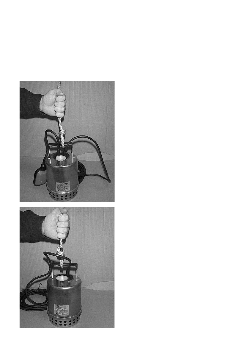
Proper Lifting:
A separate chain or rope should be attached to the handle for normal lifting.
Please note that this will help prevent damage due to inadvertent lifting of
the pump by the power cord.
Rope attached to automatic pump
for lifting and installation.
Rope attached to manual pump for
lifting and installation.
2

Contents
Section Page
General Application Information . . . . . . . . . . . . . . . . . . . . . . . . . . . . . . . . . 3
Safety Information and Introduction . . . . . . . . . . . . . . . . . . . . . . . . . . . . . . . 5
General Specifications . . . . . . . . . . . . . . . . . . . . . . . . . . . . . . . . . . . . . . . . . 6
Materials Needed and Installation Instructions . . . . . . . . . . . . . . . . . . . . . 6, 7
Electrical Information . . . . . . . . . . . . . . . . . . . . . . . . . . . . . . . . . . . . . . . . . . 8
Submersible Pump Installation . . . . . . . . . . . . . . . . . . . . . . . . . . . . . . . . . . . 9
Performance Table . . . . . . . . . . . . . . . . . . . . . . . . . . . . . . . . . . . . . . . . . . . 10
Installation Diagram . . . . . . . . . . . . . . . . . . . . . . . . . . . . . . . . . . . . . . . . . . 11
Motor Wiring Diagram. . . . . . . . . . . . . . . . . . . . . . . . . . . . . . . . . . . . . . . . . 12
Operation . . . . . . . . . . . . . . . . . . . . . . . . . . . . . . . . . . . . . . . . . . . . . . . . . . 12
Technical Specifications . . . . . . . . . . . . . . . . . . . . . . . . . . . . . . . . . . . . . . . 13
Troubleshooting Checklist . . . . . . . . . . . . . . . . . . . . . . . . . . . . . . . . . . . . . . 14
Maintenance and Service . . . . . . . . . . . . . . . . . . . . . . . . . . . . . . . . . . . . . . 15
Sectional Views . . . . . . . . . . . . . . . . . . . . . . . . . . . . . . . . . . . . . . . . . . . . . 16
Disassembly and Assembly . . . . . . . . . . . . . . . . . . . . . . . . . . . . . . . . . . . . 19
Customer Service Information . . . . . . . . . . . . . . . . . . . . . . . . . . . . . . . . . . 20
General Application Information
The Sump and Installation
If your basement does not currently have a sump installed, it would be necessary
check local plumbing codes as to the acceptable type of sump that may be used.
Materials commonly specified are: clay tile, fiberglass, steel, concrete and
It may be necessary to cut a hole in the basement floor and excavate
Plumbing and electrical contractors can advise on proper installations of drain tiles,
sump, pump and electrical service. Honda recommends that a solid sump base be
provided. The sump is fed by drain tile placed around the outside and/or inside basement walls at the footings. If applications where a gravel base must be used, to relieve
hydraulic pressure under the basement floor, be sure to provide a permanent and solid
base for the pump (bricks or a steel plate). A sump cover capable of supporting 200
pounds should be employed to contain odors and for obvious safety reasons.
for the sump.
to
polyethylene.
Electrical Installation
Electrical service for any sump pump installation must be grounded and separately fused
or breakered directly from the entrance box with a single grounding type receptacle at
the pump. The receptacle should not be less than four feet above the basement floor for
3

General Application Information
safety reasons.You should never touch a sump pump or discharge piping while the
pump is connected to electrical power and water is present. The pump should be
disconnected from the electrical source before handling in all cases.
Discharge Piping Installation
To assure the maximum performance from your sump pump, the discharge pipe size
and piping fittings should not be smaller than the discharge port of the pump. Smaller
pipe will add to friction losses and reduce the capacity of the pump. Normally accepted
materials are galvanized pipe, rigid plastic pipe or
of flexible hose between the pump discharge
in alignment, reduce vibration and noise, and will act as a union when it is necessary to
remove the pump. Where the discharge pipe is long, a check valve is often employed to
prevent the water from flowing back into the sump when the pump turns off. If the discharge
is directed into a sanitary sewer, a suitable anti-siphon device or a free flow check valve
should be inserted in the line to prevent backflow into the pit. Sump pumps are not
designed to handle raw sewage (see page 9, Septic Tank Installation). Do not attempt
to adapt one for this type of application. A sewage ejector pump especially designed to
handle solids must be used.
Pump Installation
When the sump, electrical and discharge plumbing installation is complete and ready
for the pump, clean all solid debris from the pit. Complete the plumbing connection to
the pump and then plug the pump into the electrical outlet. A few extra minutes to test
the sump pump installation are now in order. Fill the sump with water, note the turn on
and turn off level of the pump, and the pumping cycle. This will allow you to calculate
the approximate discharge flow of the pump system. If everything is operating properly,
install the sump cover.
acceptable flexible pipe or hose. A piece
and the discharge piping will provide for ease
(cont.)
Pump Selection
The pump should be of sufficient capacity and head to satisfy anticipated use requirements.
Basement perimeter water intrusion varies by area and region. Typically a 1/3 HP or 1/2
HP DRAINAGE PUMP WILL EVACUATE MOST HOME SUMP PITS.
Commercial and industrial drainage applications require that calculations of pumping
volume and pumping head be performed to determine the proper size pump is applied.
NOTE:
Pumping volume may vary seasonally due to rainfall and area run-off.
4

General Application Information
Basin and Cover
The basin should not be less than 18 inches in diameter and 24 inches deep.
Larger diameters are advisable in instances of increased pump capacity requirements:
Required Minimum
Pump Capacity Basin Diameter
up to 35 GPM 18"
over 35 GPM 24"
over 60 GPM 30"
over 100 GPM 36"
over 150 GPM 48"
The basin should be located such that all water flows into the basin due to gravity.
Outdoor installations should be at a sufficient depth to ensure protection from freezing.
Maintenance Tips
• Every three or four months:
1) Clean the pump screen or inlet opening. If your sump collects the discharge
from an automatic washing machine, cleaning will be required more often. (Before
removing the pump be sure to disconnect the unit from electrical power; and
reconnect after completion of cleaning);
2) Pour enough water into the sump to cycle the pump and assure its proper
functioning.
• Annually:
Remove and clean the pump. Clean the sump pit also.
(cont.)
Safety Information and Introduction
WARNING
Before handling this pump, always disconnect
the power first.
This pump should only be serviced by a qualified person or a factory
trained person.
CAUTION
This instruction manual includes necessary items for installation, operation
Read this manual carefully to ensure correct installation,
Be sure to keep this instruction manual on hand for future reference.
operation and maintenance.
and maintenance.
5
 Loading...