

Honda Power Equipment WB20XT2A user guide
_
Honda
WB20XT, WB30XT
OWNER’S MANUAL
Original instructions
MANUEL DE L’UTILISATEUR
Notice originale
BEDIENUNGSANLEITUNG
Originalbetriebsanleitung
MANUAL DE EXPLICACIONES
Manual original
The‘‘e-SPEC’’mark symbolizes environmentally
responsible technologies applied to Honda power
equipment, which contains our wish to ‘‘preserve
nature for generations to come.’’
09/08/01 11:40:13 32YG3610_002
Thank you for purchasing a Honda water pump.
This manual covers the operation and maintenance of Honda water
pump:
WB20XT/WB30XT
All information in this publication is based on the latest product
information available at the time of approval for printing.
Honda Motor Co., Ltd. reserves the right to make changes at any time
without notice and without incurring any obligation.
No part of this publication may be reproduced without written
permission.
This manual should be considered a permanent part of the pump and
should remain with the pump if it is resold.
The illustrations in this manual are based on:
WB20XT
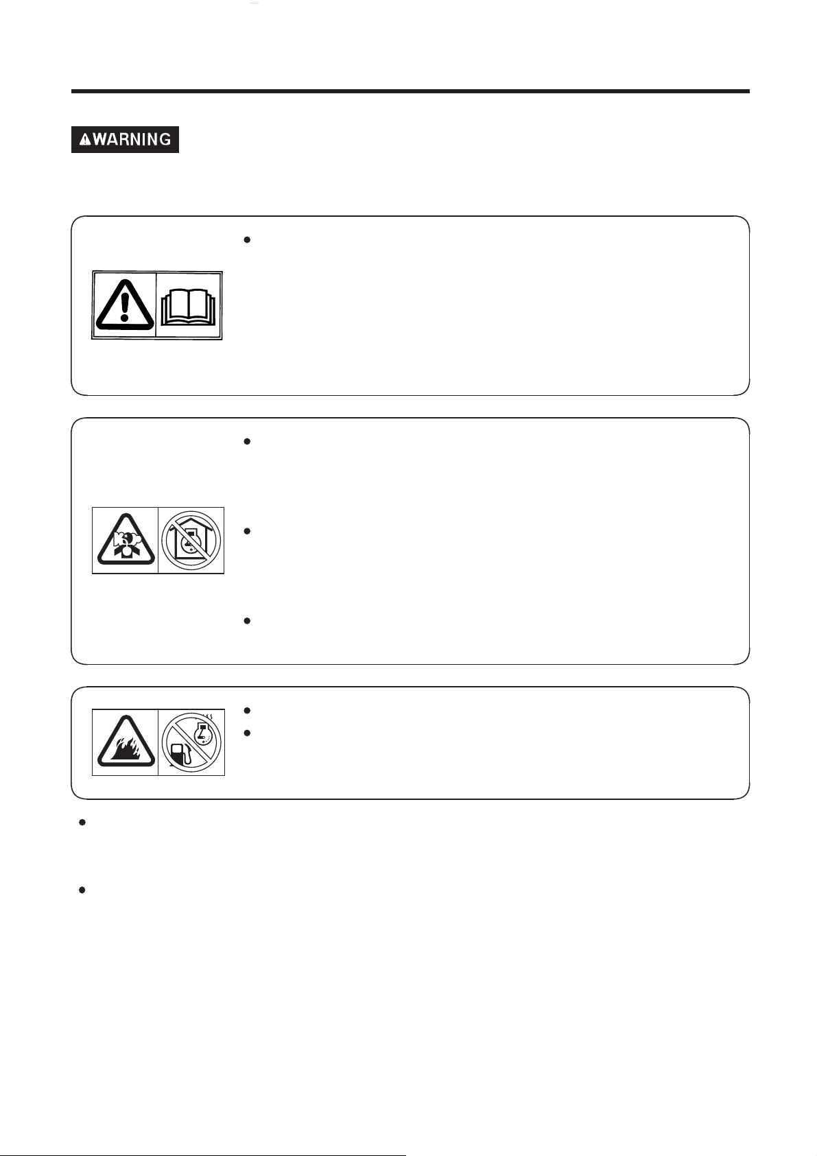
Pay special attention to statements preceded by the following words:
Indicates a strong possibility of severe personal injury or
death if instructions are not followed.
Indicates a possibility of equipment or property damage if
instructions are not followed.
Gives helpful information.
If a problem should arise, or if you have any questions about the
pump, consult an authorized Honda dealer.
Honda water pump is designed to give safe and dependable service if
operated according to instructions.
Read and understand the O wner’s Manual before operating the water pump. Failure to do so could result in personal injury or equipment damage.
The illustration may vary according to the type.

09/08/01 11:40:16 32YG3610_003
Disposal
To protect the environment, do not dispose of this product,
battery, engine oil, etc. carelessly by leaving them in the waste.
Observe the local laws and regulations or consult your authorized
Honda dealer for disposal.
1

09/08/01 11:40:19 32YG3610_004
CONTENTS
.......................................................................................6. OPERATION .18
.................................................................................8. MAINTENANCE .20
EC Declaration of Conformity
.......................................................................1. SAFETY INSTRUCTION .3
..............................................................2. SAFETY LABEL LOCATIONS .5
.....................................................CE mark and noise label locations .6
.........................................................3. COMPONENT IDENTIFICATION .7
......................................................4. PRE-OPERATION FOR STARTING .9
...................................................................5. STARTING THE ENGINE .15
..................................................................High altitude operation .17
...................................................................7. STOPPING THE ENGINE .19
.............................................................9. TRANSPORTING/STORAGE .27
........................................................................10. TROUBLESHOOTING .29
...............................................................................11. SPECIFICATIONS .31
................MAJOR Honda DISTRIBUTOR ADDRESSES .Inside back cover
.......‘‘ ’’ CONTENT OUTLINE . Inside back cover
2
09/08/01 11:40:27 32YG3610_005
SAFETY INSTRUCTION1.
To ensure safe operation
Honda water pump is designed to give safe and
dependable service if operated according to instructions.
Read and understand the Owner’s Manual before operating the w at er pump. Failure to do so
could result in personal injury or equipment damage.
Exhaust contains poisonous carbon monoxide, a
colorless, od orless gas. Brea thing c arbon
monoxide can cause loss of consciousness and
may lead to death.
If you run the pump in an area that is confined,
or even partially enclosed area, the air you
breathe could contain a dangerous amount of
exhaust gas.
Never run your pump inside a garage, house or
near open windows or doors.
−
Stop the engine before refueling.
Gasoline is extremely flammable and explosive
under certain conditions. Refuel in a well
ventilated area with the engine stopped.
Be careful not to spill fuel when refueling. Spilled fuel or fuel vapor
may ignite. If any fuel is spilled, make sure the area is dry before
starting the engine.
Never run the engine in an enclosed or confined area. Exhaust gas
contains poisonous carbon monoxide gas; exposure can cause loss
of consciousness and may lead to death.
3

09/08/01 11:40:33 32YG3610_006
To ensure safe operation
Always make a pre-operation inspection (page ) before you start
the engine. You may prevent an accident or equipment damage.
For safety, never pump flammable or corrosive liquids such as
gasoline or acid. Also, to avoid pump corrosion, never pump sea
water, chemical solutions, or caustic liquids such as used oil, wine,
or milk.
Place the pump on a firm, level surface. If the pump is tilted or
overturned, fuel spillage may result.
To prevent fire hazards and to provide adequate ventilation, keep
the pump at least 1 meter (3 feet) away from building walls and
other equipment during operation. Do not place flammable objects
close to the pump.
Children and pets must be kept away from the area of operation
due to a possibility of burns from the hot engine components.
Know how to stop the pump quickly, and understand the operation
of all controls. Never permit anyone to operate the pump without
proper instructions.
−
9
4
09/08/01 11:40:41 32YG3610_007
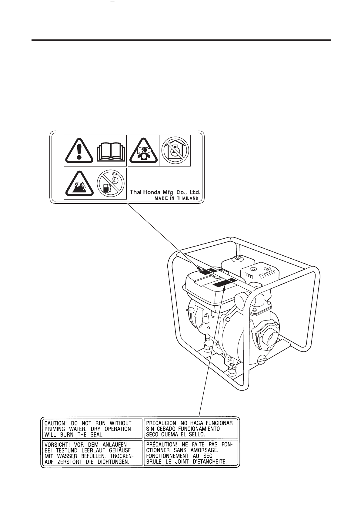
These labels warn you of potential hazards that can cause serious injury. Read the labels and safety notes and precautions described in this
manual carefully.
If a label comes off or becomes hard to read, contact your Honda dealer for a replacement.
OPERATOR CAUTION [For European types]
SAFETY LABEL LOCATIONS2.
PUMP CAUTION [For Australian types]
5

09/08/01 11:40:47 32YG3610_008
CE mark and noise label locations
[For European types]
CE MARK [Example: WB20XT]
Manufacturer and address
Model
Sales agency and address
Year of manufacture
Dry mass
6
NOISE LABEL
[Example: WB20XT]
09/08/01 11:40:54 32YG3610_009
〈〉
WB20XT
THROTTLE LEVER
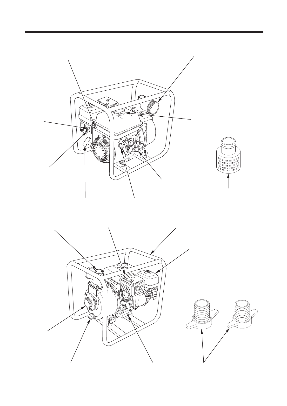
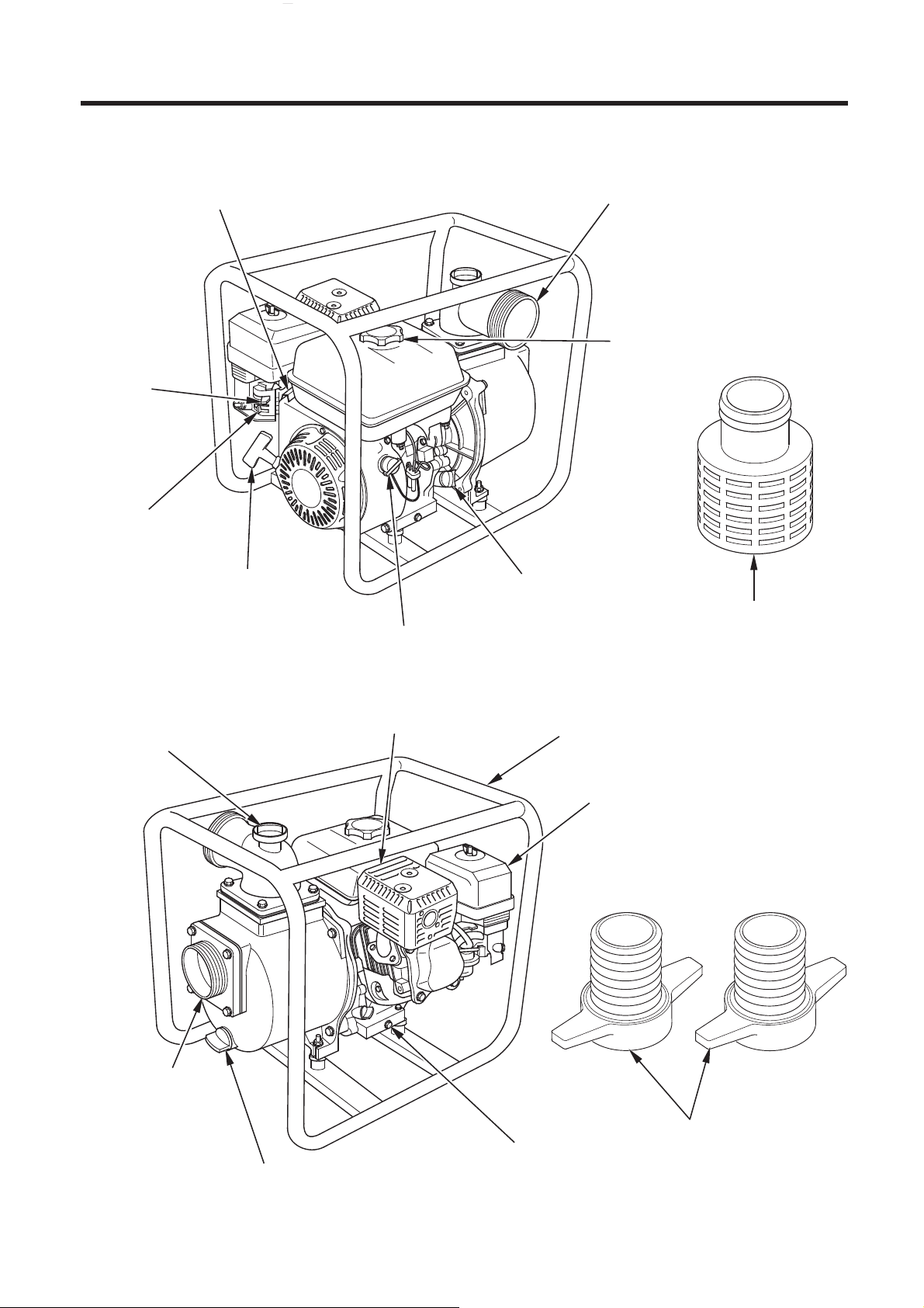
COMPONENT IDENTIFICATION3.
DISCHARGE PORT
CHOKE
LEVER
FUEL VALVE LEVER
STARTER GRIP
PRIMING WATER
FILLER CAP
FUEL FILLER CAP
OIL FILLER CAP/
DIPSTICK
STRAINER
ENGINE SWITCH
MUFFLER FRAME
AIR CLEANER
SUCTION PORT
PUMP DRAIN PLUG
OIL DRAIN PLUG
HOSE
CONNECTOR
7
09/08/01 11:41:00 32YG3610_010
〈〉
WB30XT
THROTTLE LEVER
CHOKE
LEVER
FUEL VALVE
LEVER
STARTER GRIP
DISCHARGE PORT
FUEL FILLER CAP
OIL FILLER CAP/
DIPSTICK
STRAINER
ENGINE SWITCH
PRIMING WATER
FILLER CAP
SUCTION PORT
PUMP DRAIN PLUG
MUFFLER
FRAME
AIR CLEANER
HOSE CONNECTOR
OIL DRAIN PLUG
8
09/08/01 11:41:08 32YG3610_011
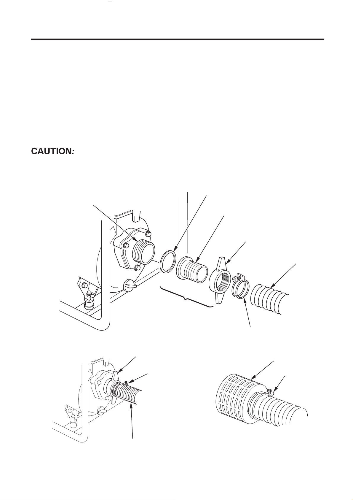
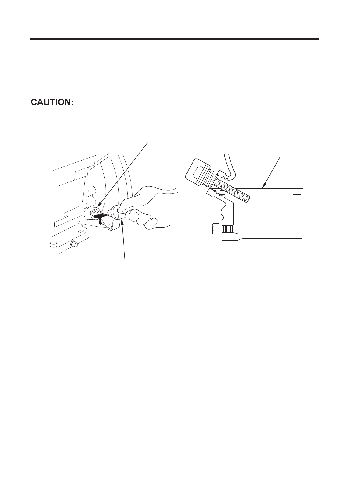
Connect the suction hose.
1.
Use commercially available hose, hose connector, and hose bands.
The suction hose must be of reinforced, noncollapsible construction.
Suction hose length should not be longer than necessary, as pump
performance is best when the pump is not far above the water level.
Self-priming time is also proportional to hose length.
The strainer that is provided with the pump should be attached to the
end of the suction hose with a band, as shown.
Always install the strainer on the end of the suction hose before
pumping. The strainer will exclude debris that can cause clogging or
impeller damage.
SUCTION PORT
PRE-OPERATION FOR STARTING4.
SEALING WASHER
HOSE
CONNECTOR
HOSE CONNECTOR
HOSE BAND
HOSE COUPLING
HOSE CLAMP RING
SUCTION HOSE
HOSE BAND
STRAINER
HOSE BAND
SUCTION HOSE
9
09/08/01 11:41:16 32YG3610_012
Connect the discharge hose.
2.
Use a commercially available hose, hose connector, and hose band. A
short, large-diameter hose is most efficient. Long or small-diameter
hose increases fluid friction and reduces pump output.
Tighten the hose band securely to prevent the hose from
disconnecting under high pressure.
HOSE BAND
DISCHARGE HOSE
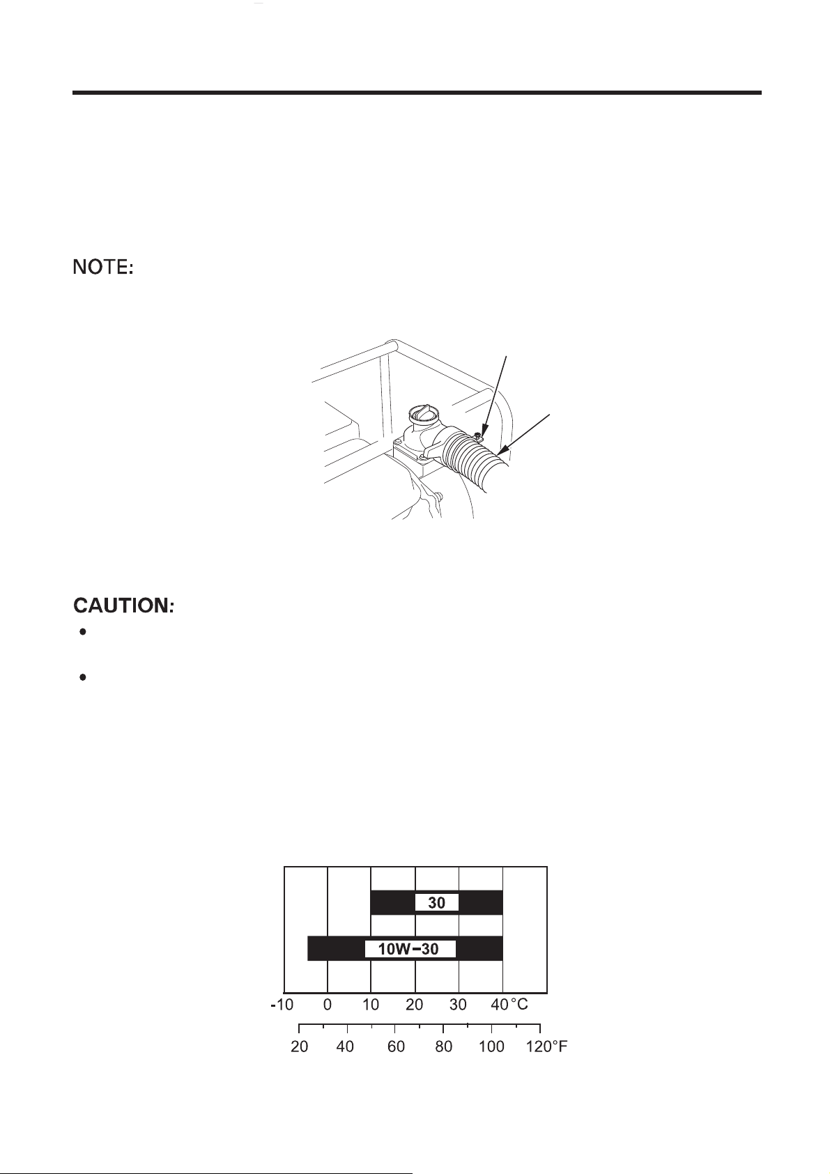
Check the engine oil level.
3.
Engine oil is a major factor affecting engine performance and
service life. Nondetergent or vegetable oils are not recommended.
Check the oil level with the pump on a level surface and the engine
stopped.
Use high-detergent, premium quality 4-stroke engine oil, certified to
meet or exceed U.S. automobile manufacturer’s requirements for API
service category SE or later (or equivalent).
Select the appropriate viscosity for the average temperature in your
area.
10
AMBIENT TEMPERATURE
09/08/01 11:41:22 32YG3610_013
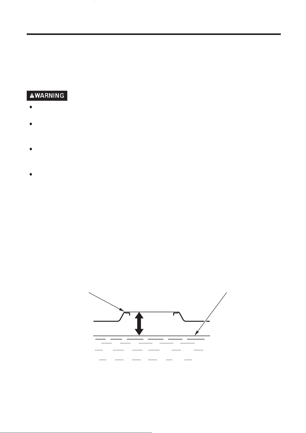
Remove the oil filler cap/dipstick and wipe it clean.
Insert the filler cap/dipstick into the oil filler neck, but do not screw it in.
If the level is low, fill to the top of the oil filler neck with the recommended oil.
Running the engine with insufficient oil can cause serious engine
damage.
OIL FILLER NECK
UPPER LIMIT
OIL FILLER CAP
Oil Alert System (Where equipped)
The Oil Alert System is designed to prevent engine damage caused by
an insufficient amount of oil in the crankcase. Before the oil level in the
crankcase can fall below a safe limit, the Oil Alert System will automatically stop the engine (the engine switch will remain in the ON
position).
If the engine stops and will not restart, check the engine oil level
before troubleshooting in other areas.
11
09/08/01 11:41:30 32YG3610_014
Check the fuel level.
4.
Use automotive unleaded gasoline with a Research Octane Number of
91 or higher (a Pump Octane Number of 86 or higher).
Never use stale or contaminated gasoline or an oil/gasoline mixture.
Avoid getting dirt or water in the fuel tank.
Gasoline is extremely flammable and is explosive under certain
conditions.
Refuel in a well-ventilated area with the engine stopped. Do not
smoke or allow flames or sparks in the refueling area or where
gasoline is stored.
Be careful not to spill fuel when refueling. Spilled fuel or fuel vapor
may ignite. If any fuel is spilled, make sure the area is dry before
starting the engine.
Avoid repeated or prolonged contact with skin or breathing of
vapor.
KEEP OUT OF REACH OF CHILDREN.
With the engine stopped and on a level surface, remove the fuel tank
cap and check the fuel level.
Refill the tank if the fuel level is low.
Do not fill the fuel tank completely. Fill tank to approximately 25 mm (1
inch) below the top of the fuel tank to allow for fuel expansion. If may
be necessary to lower the fuel level depending on operating
conditions.
After refueling, make sure the tank cap is closed properly and securely.
FUEL TANK TOP MAXIMUM FUEL LEVEL
25 mm
(1 inch)
12
 Loading...