

Page 1
PROVISIONAL FINAL
HTI NUMBER: TI-62002082
DATE OF ISSUE: 2002/10/24
Honda Technical Information
DATE OF REVISION:
MODEL: BF15D / BF20D YOUR REFERENCE NO.
SUBJECT:FUEL LEAK WHEN IN FULLY TILT UP POSITION
N/A
SYMPTOM:
Fuel may leak slight ly out of the outboard motor under
the following conditions:
1. Engine is stopped after widely open throttle
operation.
2. The outboard motor is fully tilted up and tipped
to the right-turn position.
3. It is kept in that position for 1.5~8 minutes.
CAUSE:
Due to vaporised Gasoline in the fuel pump, the
internal pressure of the fuel pump rose, allowing
liquid gasoline in the fuel chamber flow into the
carburettor. And the gasoline that flowed into the
carburettor leaked o ut of the carburettor through the
main nozzle.
COUNTERMEASURE:
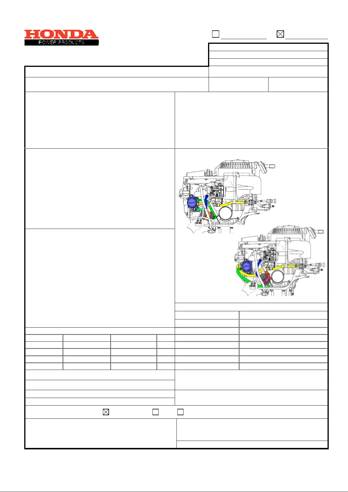
1. The installation direction of the fuel pump has been
changed 180 degrees to prevent fuel from flowing
out even if it vaporizes.
2. The installation direction of the fuel chamber has
been changed not to drain liquid gasoline to the
carburettor, but to let vapour gasoline flow into the
chamber.
3. As the installation direction of the two above
components was chan ged, the length and s hape of
the fuel hoses have been changed, too.
APPLICATION ON PRODUCTION LINE
MODEL SERIAL PREFIX SERIAL NO.FRT
BF15D3 BALJ 1002828 0.5 90503-ZV4-000 6mm washer
BF20D3 BAMJ 1002875 0.5 95005-1100130M 11x20 tube (Cutting to use)
WARRANTY APPLICATION:
MAIN CAUSAL PART:
WARRANTY DEFECT CODE:
QIS NUMBER:
Ordinary
16700-ZW9/16790-ZY1
060
AP2002090611151
M
ARKET TREATMENT:
If the symptom mentioned on the left is confirmed,
replace the part with the countermeasure part listed
below.
ILLUSTRATION
Before C/M
After C/M
SERVICE PARTS INFORMATION
PARTS NUMBER PARTS DESCRIPTION
16861-ZY1-010 Fuel tube B
17702-ZY1-010 Fuel tube C
17701-ZY1-010 Fuel tube D
90679-SG9-E01 Tie wrap
(91303-ZW9-000) O-ring (Replace new one)
PARTS AVAILABILITY:
Will be available in the middle of November.
P
ARTS TREATMENT:
Necessary
DEALER NOTICE: Bulletin Orally Not necessary
NOTES:
101, 120, 130, 23D, 231, 235, 2 37, 240, 25F, 26 E, 267,
272, 28R, 350, 374, 41C, 430, 4 60, 504, 507, 5 22, 550,
741, 776
Issued by Manager
T. Warabi T. Kubota
Power Product Service Division
DISTRIBUTION: All
1/4
Page 2
ANNEX
)
p
HTI NUMBER: TI-62002082
DATE OF ISSUE: 2002/10/24
Honda Technic al I nformation
ATE OF REVISION:
D
MODEL: BF15D / BF20D YOUR REFERENCE NO.
N/A
SUBJECT:FUEL LEAK WHEN IN FULLY TILT UP POSITION
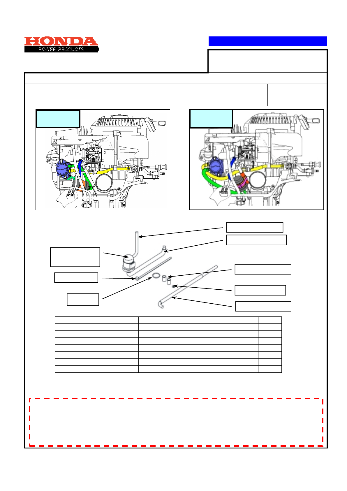
Before
replacement
(A) Necessary parts.
Fuel chamber
(not included)
10.Tie wra
After
replacement
3. Fuel tube D
1. Fuel tube C
9. 11 x 20 tube (2
8. 6 mm washer
11. O-ring
2. Fuel tube B
No. Part Number Part Name Q'ty
1 16861-ZY1-010 Tube B, fuel 1
2 17702-ZY1-010 Tube C, fuel 1
3 17701-ZY1-010 Tube D, fuel 1
8 90503-ZV4-000 6 mm washer 1
9 95005-1100130M Tube, 11 x 20 (To be cut into 20mm) 2
10 90679-SG9-E01 Tie wrap 1
11 91303-ZW9-000 O-ring 1
(B) Preparation before work
N Because this work involves changes of fuel tubes, fuel remaining in the related parts leaks. Be
careful not to allow fuel to le ak to the outside using shop cloth.
N Before starting work, make sure that there is no flame nearby. (Remove the terminals if a
battery is equipped.)
N Be careful not to allow dust to enter during work.
N Remove the fuel connector.
2/4
Page 3
ANNEX
HTI NUMBER: TI-62002082
DATE OF ISSUE: 2002/10/24
Honda Technic al I nformation
ATE OF REVISION:
D
MODEL: BF15D / BF20D YOUR REFERENCE NO.
N/A
SUBJECT:FUEL LEAK WHEN IN FULLY TILT UP POSITION
(C) Work
1-1. Remove the undercover on the re ar side.
1-2. Remove the water pilot tube and carburet or drain tube from
the undercover on the right.
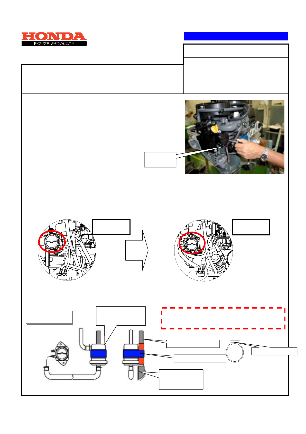
2. Remove the engine side stopper, and then remov e t he fu el
chamber stay (not reusable).
Engine side
stopper
3-1. Remove the fuel tubes B and C of the fuel pump, and remove the fuel pump from th is unit.
[Note] Replace the O-ring of the fuel pu mp with the supplied O-ring.
3-2. Invert the direction of the fuel pump by 180 d egrees, and install it.
Tightening torque of 6 x 22 flange bolt: 12 Nm
Before
replacement
After
replacement
4-1. Pull out the oil level gauge, and insert the 11 x 20 mm t ube into the oil level pipe as far as it will go.
4-2. Insert the slit of the fuel chamber suspension of the subassembled kit into the oil level pipe.
4-3. Similarly insert the second 11 x 20 mm tub e int o the oil level pipe, an d install the oil level gauge.
Installed position
and direction
Insert the chamber
with its direction as
shown in illustration.
Apply soap suds when installing the 11 x 20 mm tube and
rubber suspension. Be sure to insert them as far as they
will go without any clearance.
Oil level pipe
Suspension slit
Suspension
11 x 20 tube
Make 2 pcs at
20mm length
3/4
Page 4
ANNEX
r
f
r
p
HTI NUMBER: TI-62002082
DATE OF ISSUE: 2002/10/24
Honda Technic al I nformation
ATE OF REVISION:
D
MODEL: BF15D / BF20D YOUR REFERENCE NO.
N/A
SUBJECT:FUEL LEAK WHEN IN FULLY TILT UP POSITION
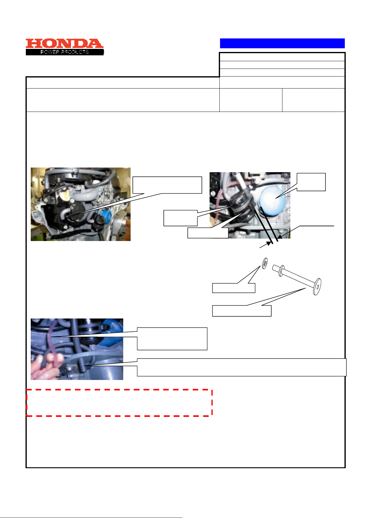
5-1. Install each fuel tube of the kit. Reuse the tube clip and clamp.
5-2. Install the fuel tube B on the joint on the upp er side of the pump.
5.3 Adjust the chamber position so that clearance between the oil filter cartridge and fuel chamber will be
approx.
15 mm as shown in the illustration below, and then secure the chamber with a tie wrap. After
securing it with the tie wrap, cut t he surplus end.
Tube B for upper joint
Tube C for lower joint
Fuel
chambe
Tie wra
6. Mount a new 6 mm washer on the engin e side stopper before installat ion.
Tightening torque of engine side stopper: 10 Nm
6 mm washe
7. Installation of water check tube and carburetor drain tube
Pass the carburetor drain
tube between the fuel tube
B and fuel tube C.
Engine side stopper
Oil filter
cartridge
15 mm
Do not block the water pilot hole tube. (Avoid blockage by taking a large bend
radius through passing the tube under the chamber.)
8. Conn ect the fuel connector from the f uel tank before installing
the rear undercover. Check for fuel leakage from each joint o
the tube by supplying fuel with the primary pump.
9. Install the undercover.
Tightening torque of 5 x 10 screw was her: 4. 5 N m
10. Check that the tube does not interf ere w ith t he undercover.
11. Install the battery terminals re moved for preparation work.
[END]
4/4
 Loading...