

Page 1
Instructions for the Estart Kit XR400
Read the instructions before you do anything and if there are questions call 408.924.0139
First off you must be competent with basic hand tools and be patient otherwise you might break a lot
of things. The only special tool required is a Honda Fly Wheel Puller, which can be had at any local
bike store.
Lets begin. First put the bike on a Jack or stand and drain all of the oil. There is a plug by the
alternator side to help drain the left side.
Remove the seat, tank, skid plate shift lever, and the connectors from the alternator cover. You will
have to remove the crank vent assembly; now I can’t legally tell you to throw it as faraway as possible
but when they stick and they do it will blow out every seal in your motor. Now I can’t tell you to
replace it but I have seen people run a hose up to the air box and put on a little uni-filter. Keep it high
up if you forge deep streams. Remember I can’t tell you to do this so if you do its on your on accord.
Next remove the alternator cover from the motor. Pull out the stud that’s left in the engine case. Now
carefully remove the three 8mm screw and 2 8mm screws holding the stator and pick-up. (Hint
degreases every thing makes life easier). Be aware of how the cable and cable hold-downs are
situated.
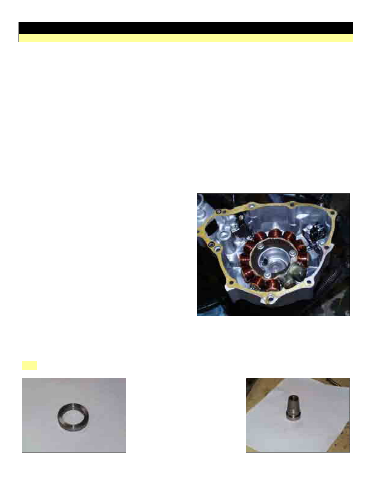
Now carefully install the stator (hopefully you got a
200 watt version) and pick-up in the new cover use
locktite on the screws (just a little please). Bend the
cable tabs a bit to make sure it does not rub. You
may have to pull the wires through the rubber
grommet, as some stators are a little short. It is
imperative that there is enough strain relief in the
harness.
Remove the Alternator/flywheel, and inspect the key
to make sure there are no burrs or distortions.
Check the crank to make sure it’s clean and
smooth. If not sand with Emory cloth. It is
imperative that there are no high spots or burrs
other wise you will experience the sadness of your
bike dying due to shavings collecting on the coils
from the fly wheel rubbing.
Now in stall the Shim marked P1, (This is the thicker of the two shims) follow with the crank adapter.
Hint: Rotate motor so key is facing up.
Crank adapter
1
Page 2
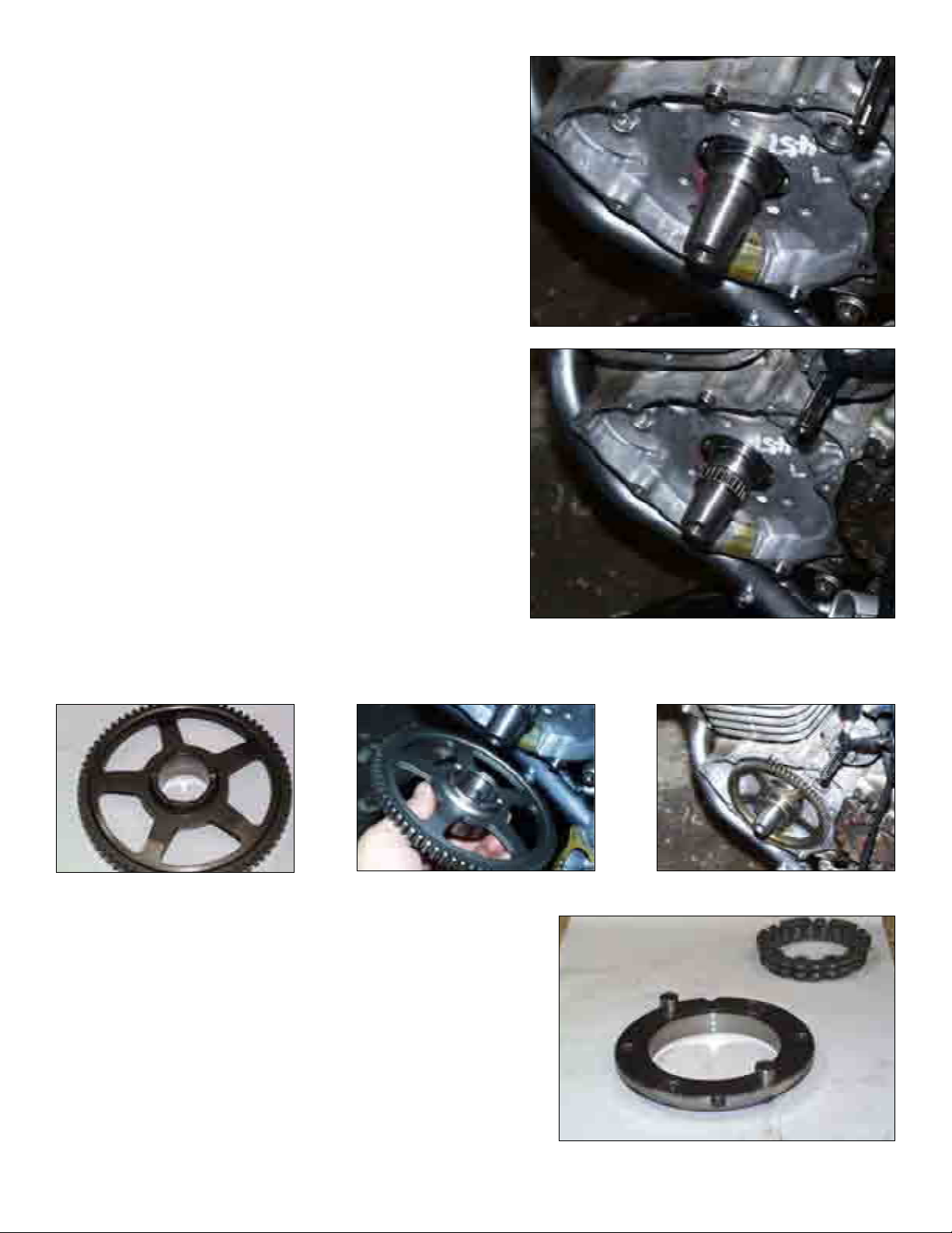
Tap the crank adapter with a soft mallet to help set it in
place. If you have a dial indicator it would be a good
time to check the run out.
Install the Joeracer key in the adapter making sure that
it is sitting flush and snug with no burrs folds spindles
or mutilations.
Next install the needle bearing over the adapter
making sure to grease well.
Now install part 3 from the clutch assembly sketch, paying attention to the correct direction the gear is
in-stalled.
The thin shim goes in the pocket of the gear facing out
Now per the picture carefully install the clutch bearing
assembly in the hub (part 5 in to part 4) and then in stall
over the large gear assembly part 3
2
Page 3
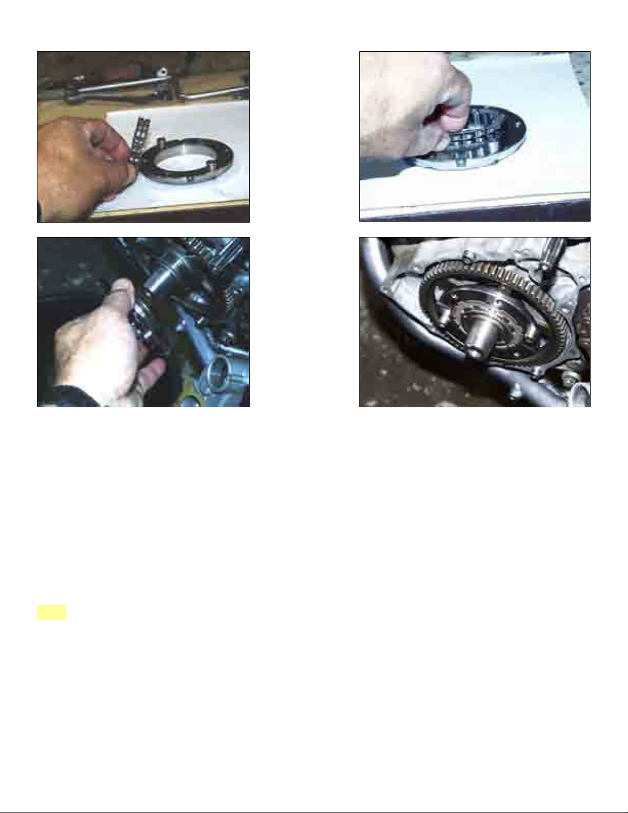
Note the position of ft the key and the drive pins. Make sure everything rotates freely and apply a libbrial
amount of motor oil. (At this point the clutch will only rotate freely in one direction. In stall the second
shim (part 9 from the clutch assembly sketch Honda part).
Now carefully align the flywheel to the key, you will have to rotate the clutch assembly to align the
drive holes with the 2 holes in the flywheel. Carefully! Tap the flywheel in place.
If it doesn’t want to go on easily, you may have to either remove the clutch outer hub and bearing
assembly and attach to the flywheel, and then assemble to the clutch gear. NOTE! There are two sets
of drive screws included. The button heads and the machined socket heads. For some flywheels that
are of the 98 and earlier the machined socket heads are the only ones that will fit. Locktite and torque
to 20 ft. lbs.
Note: The correct direction of the key is the wide section in horizontal plane.
The flywheel should be attached to the drive clutch plate. The button heads go through the flywheel
and attach the in the plate. The socket heads are a pin drive where they float.
The upper pictures show the drive pins (socket heads) installed prior to the flywheel installation. This
may not be possible on all bikes; the button heads would go on after the flywheel is installed.
3
Page 4
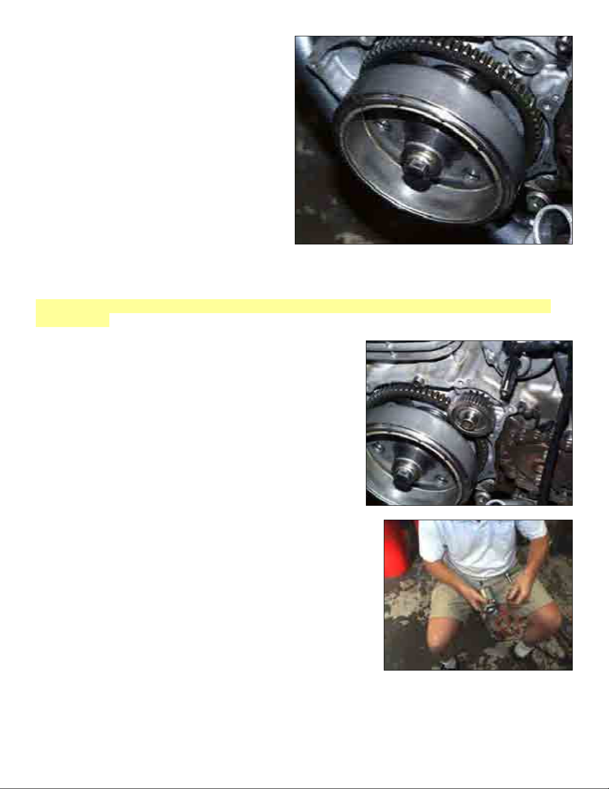
We no longer use the machined socket
head screws.
The button heads should be installed last after
the flywheel is torqued down and the assembly
is rotates to center the clutch.
Through the two holes in the fly wheel install
the button heads and locktite torqued to
20 ft. lbs.
Now install the 75x12x1.25 mm bolt, washer (use the original) and lock washer and torque down to
70 ft.lbs. (no more no less if you do it will distort the crank adapter).
Note: Don’t use an impact wrench; if you do you’ll come back to me crying and I’ll have to verbally
assuault you.
Don’t be afraid to use a good deal of locktite. Make sure all
of the threads are cleaned with brake clean or carb cleaner.
Again if you have a dial indicator checks the run out of the
inside of the flywheel. Next install part 1 and part 6 from the
sketch. Which is the double gear and corresponding pin.
Locate the starter motor from your box and the long red cable.
Install the cable on the connector leaving a little loose to adjust
later.
4
Page 5
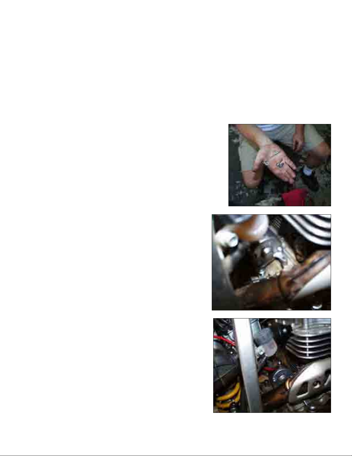
Now locate the over flow hose’s from the carb. At the engine case there is a metal rod that holds
them in place.
Remove the screw and rod, as that’s where the starter bolts to the case.
From the flywheel side slide the starter and align with the screw hole that you removed the rod from.
From your pile of old case bolts find a screw about 35 mm (1.25) or so and reinstall the metal rod on
top of the screw. Unless you are good at guessing the alignment of the starter in relation to the case
do not Locktite and tighten, as you’ll be removing later to do so.
Run the wire up to the air box area.
5
Page 6

Now is the scary part. Be very careful. Put the gasket on the engine case with the dowels. If the
dowels are on the alternator, cover case remove them and put them in the engine case. Now carefully
install the alternator. Cover. The magnets on the flywheel will want to pull it on so have a good grip. If
everything is nasty oily greasy, clean it NOW!
You will have to fudge with the starter motor to align it. Ok now if everything is in place per the
assembly drawing start putting in screws. Put in a quart of oil by pouring it through the starter drive
cover opening. This will ensure proper lubrication of all the new parts.
Now locate the starter drive housing on the new cover (should be obvious) install part 7-8-and 2, and
the cover with gasket. (Parts 20-5-24-4-9-8-13) from the alternator cover sketch. Locktite and tighten
the starter bolt.
Now is a good time to fill the engine sump with oil and start with the kick-starter to make sure there
are no funny noises and leaks. The clutch assembly will kind of whirr and whine slightly, but as the
motor warms it should all sound normal. Let it run for a good 5 minutes.
Do NOT REV IT ABOVE THE REQUIRED RPM TO KEEP A COLD MOTOR RUNNING!
If you do you run the risk of prematurely wearing out the crank adapter and bearing.
If every thing is cool then shut it down have a beer and rest.
The hard part is over and I know you anxious to fire this bike electrically!
6
Page 7

Ok having had lunch or dinner and resting, the fun starts. I won’t go in to a lot of text here. I’ll show
pictures it’s pretty easy. The most complicated part is the battery mount and air box mod. But before
we do that. Knowing that the bike runs, replace the stock CDI with the Dynatek box.
Read the directions once then read it again.
Now pull out the spark plug and make sure we got spark.
If that’s cool then follow the pictures forthwith shows.
Cut the top of the air box out being careful to not cut out the mount bolt. Follow the frame as close as
possible. This is required to provide space for air for the motor the battery takes away.
You may want to take off the filter and put a rag in the intake.
Now locate the battery, and battery mount and place in the air box so as the battery does not interfere
with removing the air filter and so it just barley sticks up to the frame rails.
Mark the inner fender with a scribe.
Next drill two holes for either a 5/26 rivet or a 10-32 screw in the middle of the brace.
Note: At last writing we found it’s easier to remove the sub frame and take out the air box when
cutting. You can get a nicer cut and closer to the edge. Also it makes installing the battery mount
much easier.
7
Page 8

Drill two matching holes in the inner fender and fasten with either the rivets or screws, use washers
on both sides. If you use screws use button heads. If you use rivets use the big head type with
backing washers. Use the straps to tie down the battery.
Note: The new battery box has two legs as opposed to an angle bracket.
The rest of the pictures show the install of the wiring. I’ll assume you know red is positive.
8
Page 9

Connect the button wires to the solenoid
harness
Location
of
button
Route on tank pad so wires wont get pinched or connectors come loose.
9
Page 10

Solenoid connector and ground strap, which connects to air filter, mount bolt.
This is the positive wire for
the Solenoid and the starter
cable, which goes to the
solenoid post.
10
Page 11

This is what it
should look like
when you getting
close.
The short cable
goes from the
battery positive to
the solenoid; the
starter cable is on
the other post.
All done!
11
Page 12

Well? What are you waiting for start your engine!
Some advice: Charge the battery fully!
Crank the motor with the release in to charge the caps in the CDI box and then freshen the fuel
charge in the cylinder.
With the choke on full hit the button for a few seconds then dump the release lever, the bike, if jetted
properly should fire right up.
The skid plate may need to be bent to clear the case and the shift lever will need to be tweaked
I bent it by putting it in a vise before the weld. In other word don’t bent it at the weld it will break!
Final words and disclaimers legal stuff; crap my lawyer made me say.
This kit has no warranty.
The CDI has a 1-year box and Honda parts have a 30-day limited warranty.
This kit is considered an aftermarket performance based add on.
Please read the instructions carefully and if you’re NOT SURE call me!
Because of the do it your self-installation I can make no guaranties on the install.
If you are colorblind challenged, I can make a black and white harness for you or get a friend to help.
The failure mode is the needle bearing doesn’t get oiled properly or the big bolt didn’t get Locktite and
the proper torque.
So again, read the instructions carefully.
12
Page 13

13
Page 14

Electric Start Option Honda
OEM parts PN 0100-1000r4
XR4004
Parts for clutch assy.
Item PN Description Qty
1 13111-KN6-930 PIN, PISTON 1
2 13111-ZE0-000 PIN, PISTON 1
3 28110-HN1-000 GEAR COMP., STARTER DRIVEN (72T) 1
4 28125-HN1-003 OUTER COMP., STARTER CLUTCH 1
6 28131-HN1-000 GEAR, STARTER REDUCTION (16T/47T) 1
7 28141-HN1-000 GEAR, STARTER IDLE (45T) 1
8 28143-HN1-000 COLLAR, STARTER IDLE GEAR 1
Parts for Cover
1 11340-HN1-000 COVER COMP., L. CRANKCASE 1
4 11370-HN1-000 COVER COMP., STARTER 1
5 11377-HN1-000 GASKET, STARTER COVER 1
6 11395-KCY-671 GASKET, L. COVER 1
8 90004-GHB-680 BOLT, FLANGE (6X28) (NSHF) 1
9 90004-GHB-700 BOLT, FLANGE (6X35) (NSHF) 1
10 90004-GHB-710 BOLT, FLANGE (6X40) (NSHF) 1
11 90004-GHB-730 BOLT, FLANGE (6X50) (NSHF) 2
12 90004-GHB-750 BOLT, FLANGE (6X60) (NSHF) 4
13 90004-GHB-760 BOLT, FLANGE (6X65) (NSHF) 2
20 94301-018140 PIN DOWEL 2
22 96001-06018-07 BOLT, FLANGE (6X18) 1
23 96001-06032-07 BOLT, FLANGE (6X32) 1
25 31200-HN1-000 MOTOR ASSY.M STARTER 1
All Cable is 10ga
27 5AH battery 1
28 Soleniod 1
28 Starter button 1
29 CDI box CDI Box from any year XR650R 1
30 Joeracer Kit 1
Total
14
 Loading...