

Page 1
INSTALLATION
HandA-Accessories.com
INSTRUCTIONS
Accessory Application Publications No.
CD/CASSETTE PLAYER
CIVIC
2- AND 4-DOOR
AII 27857
Issue Date
AUG 2004
PARTS LIST
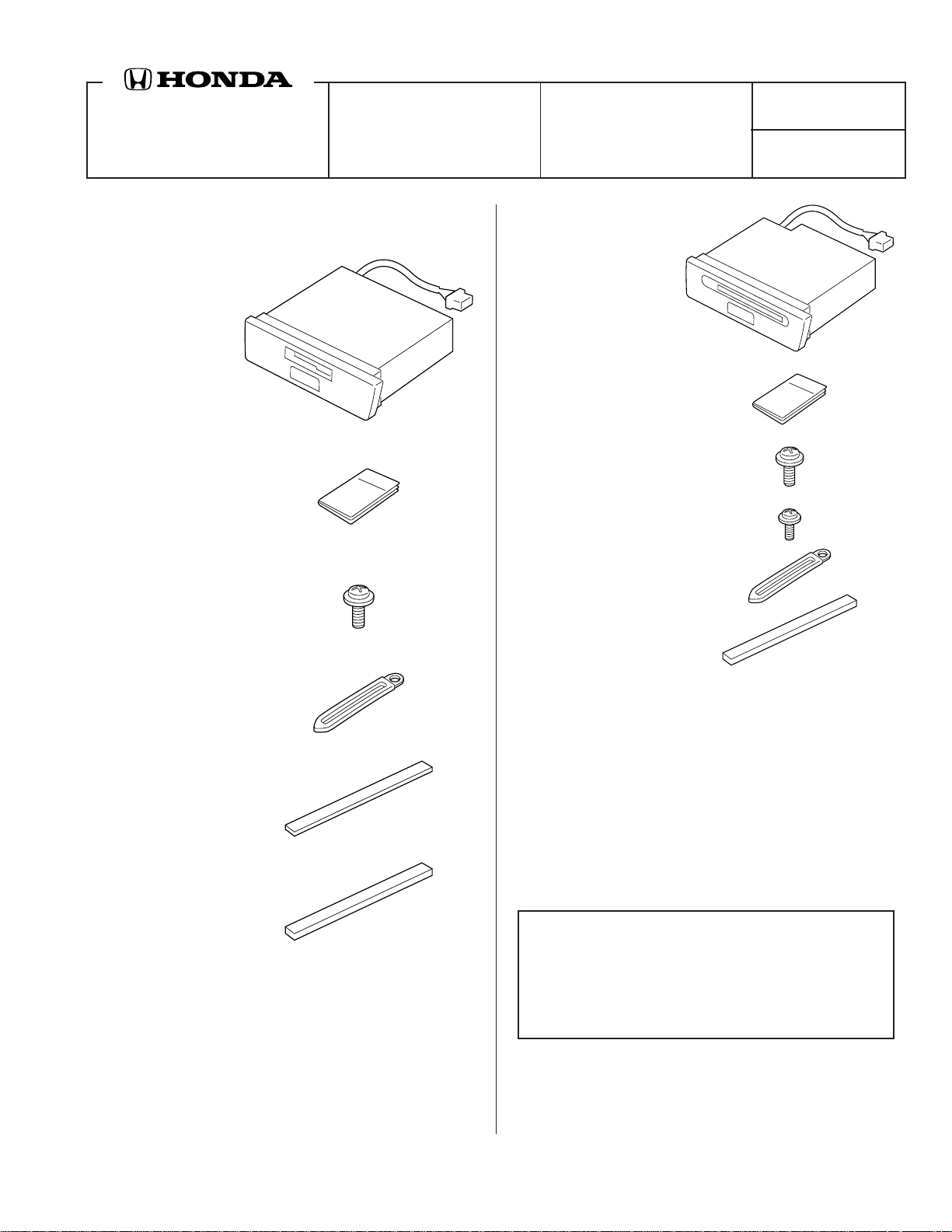
Cassette Player:
P/N 08A53-S5A-100
Cassette player
Owner’s Manual
5 Washer-screws, 5 x 8 mm
CD Player:
P/N 08A53-S5D-100
CD player
Owner’s Manual
4 Washer-screws, 5 x 8 mm
Washer-screw, 4 x 8 mm
Harness clip
Rubber pad
Harness clip
Adhesive pad
Rubber pad
TOOLS AND SUPPLIES REQUIRED
Phillips screwdriver
8 mm and 10 mm Sockets
Ratchet
Shop towel
Utility knife
Isopropyl alcohol
Tape measure
INSTALLATION
Customer Information: The information in this
installation instruction is intended for use only by
skilled technicians who have the proper tools,
equipment, and training to correctly and safely add
equipment to your vehicle. These procedures should
not be attempted by “do-it-yourselfers.”
1. Make sure you have the anti-theft code for the
radio, then write down the radio station presets.
2. Disconnect the negative cable from the battery.
© 2004 American Honda Motor Co., Inc - All Rights Reserved. AII 27857 (0408) 1 of 8
08A53-S5A-1000-91
Page 2
If the vehicle is equipped with a center console
armrest, go to step 6, otherwise; continue with step 3.
3. Pull up on the parking brake lever, then remove the
console box (nine clips).
CLIPS (9)
PARKING BRAKE
LEVER
Pull up
completely.
CONSOLE BOX
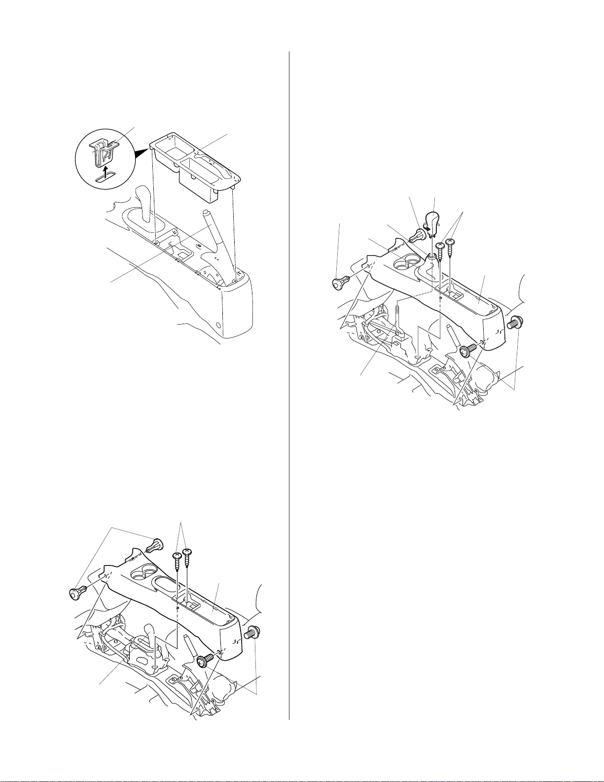
M/T Model:
• Remove the shift knob from the lever by holding
the plastic section above the boot down firmly
with one hand and turning the knob in a
counterclockwise with the other hand.
• Remove the two self-tapping screws, two
screws, and two clips that fasten the center
console and remove the console.
SHIFT
KNOB
CLIP
CLIP
PLASTIC
SECTION
BOOT
SELF-TAPPING
SCREW
CENTER
CONSOLE
4. Remove the center console.
A/T Model:
• Place the shift lever in the Neutral position.
• Remove the two self-tapping screws, two
screws, and two clips that fasten the center
console and remove the console
• If equipped with an optional seat armrest,
remove the console after reclining the seatback.
SELF-TAPPING
CLIP
SCREW
CENTER
CONSOLE
SHIFT LEVER
Place in the
Neutral position.
SCREW
3620030K
SHIFT LEVER
Place in the
Neutral position.
SCREW
3620020K
2 of 8 AII 27857 (0408) © 2004 American Honda Motor Co., Inc - All Rights Reserved.
Page 3
5. Remove the dashboard center lower cover.
Without a Cigarette Lighter and Ashtray:
• With the parking brake applied, place the gear
shift lever in the Neutral position.
• Gently pry out on the lower cover to release the
six retaining clips.
• Unplug the accessory power socket connector
(if equipped, unplug the fog light harness), and
remove the lower cover.
ACCESSORY
POWER
SOCKET
CONNECTOR
If the vehicle is not equipped with a center console
armrest, go to step 10, otherwise; continue with step 6.
6. Remove the escutcheon, and the center console
trim:
A/T Model:
• With the parking brake applied, place the shift
lever in the Neutral position.
• Pry up on the four retaining tabs and remove
the escutcheon.
• Pry up on the three clips and six retaining tabs
and remove the center console trim.
RETAINING
TABS (6)
CENTER CONSOLE
TRIM
FOG LIGHT SWITCH
CONNECTOR
(if equipped)
CLIPS (6)
DASHBOARD CENTER
LOWER COVER
FOG LIGHT
SWITCH
(if equipped)
With a Cigarette Lighter and Ashtray:
• With the parking brake applied, place the gear
shift lever in the Neutral position.
• Remove the ashtray.
• Inside the ashtray opening, remove the one
self-tapping screw securing the dashboard
center lower cover.
• Gently pry out on the lower cover to release the
six retaining clips.
ILLUMINATION
BULB
CIGARETTE
LIGHTER
CONNECTOR
ESCUTCHEON
CLIPS (3)
RETAINING
TABS (4)
RETAINING
CLIPS (6)
SELFTAPPING
SCREW
DASHBOARD CENTER
LOWER COVER
© 2004 American Honda Motor Co., Inc - All Rights Reserved. AII 27857 (0408) 3 of 8
ASHTRAY
3304120W
Page 4

M/T Model:
7. Remove the dashboard center lower cover.
• Apply the parking brake.
• Remove the shift knob from the lever by
holding the plastic section above the boot down
firmly with one hand and turning the knob
counterclockwise with the other hand.
• Pry up on the three clips and six retaining tabs
and remove the center console trim.
SHIFT KNOB
PLASTIC
SECTION
BOOT
RETAINING
TABS (6)
CLIPS (3)
Without a Cigarette Lighter and Ashtray:
• Remove the two self-tapping screws that fasten
the dashboard center lower cover.
• Gently pry out on the dashboard center lower
cover to release the rear four clips, then pull the
cover rearward to release five clips and one
retaining tab.
• Unplug the accessory power socket connector
(If equipped, unplug the fog light harness), and
remove the dashboard center lower cover.
FOG LIGHT SWITCH
(if equipped)
CLIPS (9)
RETAINING TAB
SELF-TAPPING
SCREW
DASHBOARD
CENTER
LOWER
COVER
CENTER
CONSOLE TRIM
3624030K
FOG LIGHT
SWITCH
CONNECTOR
(if equipped)
SELF-TAPPING
SCREW
ACCESSORY
SOCKET
CONNECTOR
CENTER PANEL
KNOB
HEATER
CONTROL
PANEL
4 of 8 AII 27857 (0408) © 2004 American Honda Motor Co., Inc - All Rights Reserved.
Page 5

With a Cigarette Lighter and Ashtray:
• Remove the ashtray. Inside the ashtray
opening, remove the one self-tapping screw.
• Remove the two self-tapping screws that fasten
the dashboard center lower cover.
• Gently pry out on the dashboard center lower
cover to release the rear four clips, then pull the
cover rearward to release five clips and one
retaining tab.
• Unplug the cigarette lighter connector, the
accessory power socket connector, and the
illumination bulb, then remove the lower cover.
DASHBOARD
CENTER
LOWER COVER
8. Open the center console lid, and remove the mat.
CENTER
CONSOLE
CLIPS (2)
SELFTAPPING
SCREW
MAT
CENTER
CONSOLE LID
RETAINING TAB
CIGARETTE
LIGHTER
CONNECTOR
ILLUMINATION
BULB
ASHTRAY
SELFTAPPING
SCREW
CLIPS (9)
3804020K
SCREW
SHIFT LEVER
Move to the
Neutral position.
3624040K
9. Remove the two clips, two self-tapping screws and
three screws that fasten the center console. Move
the shift lever to the Neutral position, and remove
the center console.
© 2004 American Honda Motor Co., Inc - All Rights Reserved. AII 27857 (0408) 5 of 8
Page 6

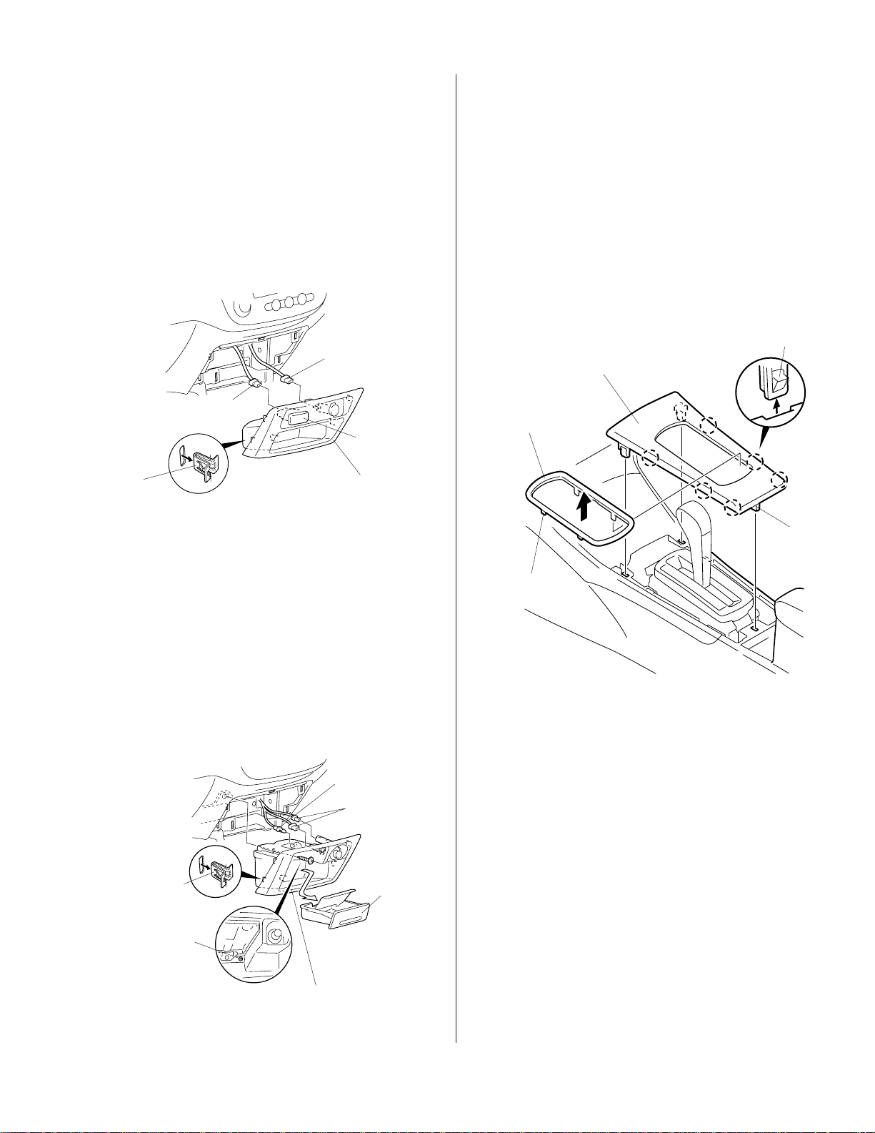
10. Remove the center panel:
• Remove the two bolts from the bottom of the
center panel.
• Reach through the bottom opening, and push
out on the center panel bracket to release the
nine clips.
• Unplug the five connectors and the antenna
lead, then remove the center panel.
CENTER
PANEL
VEHICLE HARNESS
CONNECTORS (5)
13. Remove the pocket (four self-tapping screws).
SELF-TAPPING SCREW
(Discard.)
POCKET
CENTER
PANEL
RETAINING
CLIPS (9)
CENTER
PANEL
BRACKET
Push.
BOLT
ANTENNA
LEAD
11. Gently pull out on each knob to remove them from
the heater control panel.
CENTER PANEL
SELF-TAPPING
SCREW
(Discard.)
14. Use a tape measure to measure and mark the
rubber pad as shown. Using scissors, cut the
rubber pad into three pieces. Remove the adhesive
backing from each of the rubber pads, and attach
them to the center panel in the areas shown.
RUBBER
PAD
Thoroughly clean
with isopropyl
alcohol.
RIB
40 mm
40 mm
ADHESIVE BACKING
KNOB
SELF-TAPPING
SCREW
HEATER
CONTROL
PANEL
END OF CURVE
RUBBER PAD
(Cut.)
CENTER PANEL
12. Remove the three self-tapping screws that fasten
the heater control panel to the center panel, and
remove the heater control panel.
6 of 8 AII 27857 (0408) © 2004 American Honda Motor Co., Inc - All Rights Reserved.
Page 7

If you’re installing a cassette player, continue with
step 15; otherwise, go to step 17.
15. Using a utility knife, cut off the bottom rib from the
center panel at the lower edge of the audio
opening. Remove all burrs. Before attaching the
rubber pads, thoroughly clean the areas where the
rubber pads will attach with isopropyl alcohol.
CENTER PANEL
17. Slide the CD or cassette player into the opening of
the center panel, then install the four screws
provided with the CD or cassette player.
CENTER PANEL
CD OR
CASSETTE
PLAYER
SCREWS (4)
Install in
the lower
hole.
(Provided with the
CD or cassette
player.)
Cut off the
bottom
rib.
Sectional
View
16. Remove the adhesive backing from the adhesive
pad, and attach it to the bottom of the cassette
player in the area shown.
ADHESIVE PAD
BOTTOM OF
CASSETTE PLAYER
ADHESIVE
BACKING
18. Attach the harness clip to the rear of the CD or
cassette player with the washer-screw provided.
AUDIO UNIT
HARNESS
CLIP
CONNECTOR
CD OR
CASSETTE
PLAYER
WASHER-SCREW
CD player:
4 x 8 mm washerscrew
Cassette player:
5 x 8 mm washerscrew
19. Plug the connector from the CD or cassette player
into the rear of the audio unit, and secure the harness
with the harness clip.
© 2004 American Honda Motor Co., Inc - All Rights Reserved. AII 27857 (0408) 7 of 8
Page 8

20. Reinstall the heater control panel and knobs on the
center panel.
23. Reconnect the negative cable to the battery.
24. Enter the anti-theft code, and reset the customer’s
radio station presets.
CENTER PANEL
KNOB
SELF-TAPPING
SCREWS
HEATER
CONTROL
PANEL
To reinstall the
knobs, align the flat
surface on the rod
with the flat surface
on the knob.
21. Plug in the five vehicle harness connectors, then
plug the antenna lead into the rear of the audio
unit.
22. Reinstall the center panel with the two bolts.
CENTER
PANEL
VEHICLE HARNESS
CONNECTORS (5)
25. Reset the clock.
26. Check operation of the CD or cassette player
according to the Owner’s Manual.
27. Reinstall all removed parts. Check that all clips
and fasteners are installed securely.
28. Place the Owner’s Manual for the CD player or the
cassette player in the glove box.
29. Test the operation of the accessory socket/
cigarette lighter.
NOTE: Whenever the battery is disconnected, the
driver's window AUTO function is disabled.
30. Start the engine. Push down on the driver's window
switch until the window is fully open.
31. Pull up on the driver's window switch to close the
window completely, then hold the switch for 2
seconds or more.
32. Lower and raise the driver's window to check
operation of the driver's window AUTO function.
33. Do the ECM/PCM idle learn procedure.
-
Make sure all electrical items are turned off.
-
Start the engine. Hold the engine speed at
3,000 rpm with no load (in Park or Neutral) until
the radiator fan comes on.
-
Let the engine idle for about 5 minutes with
the throttle fully closed and with all electrical
items off.
NOTE: If the radiator fan comes on during this
step, the time it operates must not be included
in the 5 minutes.
ANTENNA
LEAD
BOLT
(reused)
8 of 8 AII 27857 (0408) © 2004 American Honda Motor Co., Inc - All Rights Reserved.
 Loading...