

Page 1
Page 2
INTRODUCTION
TO THE OWNER
Read this manual before operating your mower. The information presented will prepare you to do a better
and safer job. Keep this manual handy for ready reference.
The mower you have purchased has been carefully engineered and manufactured to provide dependable
and satisfactory use. Like all mechanical products, it will require cleaning and upkeep. Lubricate the
mower as specified. Observe all safety information in this manual and safety decals on the mower and
tractor.
For service, your authorized dealer has trained mechanics, genuine service parts, and the necessary tools
and equipment to handle all your needs.
Use only genuine service parts. Substitute parts may not meet standards required for safe and satisfac-
tory operation. Record the serial number of your mower:
Model MM52 Rotary Mower
Serial Number
(see Safety Decal page for location)
Provide this information to your dealer to obtain correct repair parts.
Throughout this manual, the term NOTICE is used to indicate that failure to observe this instruction can
cause damage to equipment. The terms CAUTION, WARNING and DANGER are used in conjunction with
the Safety-Alert Symbol, (a triangle with an exclamation mark), to indicate the degree of hazard for items of
personal safety.
The Safety-Alert Symbol means ATTENTION! BECOME ALERT!
YOUR SAFETY IS INVOLVED!
! ’
m Denotes a reminder of safety practices or directs attention to unsafe practices
l
which could result in personal injury if proper precautions are not taken.
! I-
C Denotes a hazard exists which can result in injury or death if proper precautions
are not taken.
D*
m Denotes an extreme intrinsic hazard exists which would result in high probability
of death or irreparable injury if proper precautions are not taken.
1
Page 3
INTRODUCTION
GENERAL INFORMATION
The purpose of this manual is to assist the operator in maintaining and operating this mower. Read
it carefully. It furnishes information and instructions
that will help you achieve years of dependable
performance. These operating and maintenance
instructions have been compiled from extensive
field experience and engineering data. Some
information may be general in nature due to
unknown and varying conditions. However, you
should be able to develop operating procedures
suitable to your particular situation.
The illustrations and data used in this manual were
current at the time of printing, but due to possible
in-line production changes, your machine may
vary slightly in detail. We reserve the right to
redesign and change the machine as may be
necessary without notification.
*
1.
m Some Illustrations In this manual
show the mower with safety shields removed
to provide a better view. The mower should
never be operated with any safety shielding
removed.
Throughout this manual, references are made to
right and left directions. These are determined by
standing behind the equipment and facing the
direction of forward travel. Blade rotation is clock-
wise as viewed from the top of the mower.
2
Page 4
CONTENTS
...................................................................................................................................................................................
INTRODUCTION
TO THE OWNER
GENERAL INFORMATION
SAFETY INFORMATION
SAFETY RULES
SET-UP AND ASSEMBLY
DEALER SET-UP INSTRUCTIONS
CHECKING
INSTALLING MOWER
INSTALLING FRONT TENSIONER BRACKET
INSTALLING LIFT LINK
ASSEMBLING MOWER DECK
INSTALLING
LEVELING MOWER DECK
INSTALLING
DETACHING MOWER
PRE-OPERATION CHECKS
CLEANING MOWER DECK (EXTERIOR)
DECK DRIVE BELT
CHECKING
ADJUSTING CUTTING HEIGHT
LOWERING
. . . . . . . . . . . . . . . . . . . . . . . . . . . . . . . . . . . . . . . . . . . . . . . . . . . . . . . . . . . . . . . . . . . . . . . . . . . . . . . . . . . . . . . . . . . . . . . . . . . . . . . . . . . . . . . . . . . . .
. . . . . . . . . . . . . . . . . . . . . . . . . . . . . . . . . . . . . . . . . . . . . . . . . . . . . . . . . . . . . . . . . . . . . . . . . . . . . . . . . . . . . . . . . . . . . . . . . . . . .
. . . . . . . . . . . . . . . . . . . . . . . . . . . . . . . . . . . . . . . . . . . . . . . . . . . . . . . . . . . . . . . . . . . . . . . . . . . . . . . . . . . . . . . . . . . . . . . . . . . . . . . . . . . . . . . . . . . . . .
PARTS . . . . . . . . . . . . . . . . . . . . . . . . . . . . . . . . . . . . . . . . . . . . . . . . . . . . . . . . . . . . . . . . . . . . . . . . . . . . . . . . . . . . . . . . . . . . . . . . . . . . . . . . . . . . . . . . .
.........................................................................................................
.............................................................................................
MOWER DECK..
DECK BELT.. ...................................................................................................
...........................................................................................................
...............................................................................................................
BLADE CONDITION..
SPEED ADJUSTMENT.. ..................................................................................
..............................................................................................
...................................................................................................
1
:
4
4
8
. . . . . . . . . . . . . . . . . . . . . . . . . ..*............................................................
i
11
....................................................................
1:
i:
i:
25
27
............................................................................
:5
;;
.31
OPERATIONS
STARTING
STOPPING
MOWING ................................................................................................................................
CUTTING PATTERNS
MAINTENANCE
LUBRICATION INFORMATION
SERVICING THE BLADES
SPINDLE REPAIR
REPLACING THE BELTS
CLEANING
STORAGE
TROUBLESHOOTING
SPECIFICATIONS
WARRANTY SERVICE
OWNER SATISFACTION
.............................................................................................................................
.............................................................................................................................
...........................................................................................................
............................................................................................
....................................................................................................
.................................................................................................................
......................................................................................................
MOWER DECK ..................................................................................................
. . . . . . . . . . . . . . . . . . . . . . . . . . . . . . . . . . . . . . . . . . . . . . . . . . . . . . . . . . . . . . . . . . . . . . . . . . . . . . . . . . . . . . . . . . . . . . . . . . . . . .
32
z
::
‘34
::
39
z
47
50
50
3
Page 5
SAFETY INFORMATION
Safety is a primary concern in the design and
manufacture of our products. Unfortunately,
our efforts to provide safe equipment can be
wiped out by a single careless act of an
operator.
In addition to the design and configuration of
equipment, hazard control and accident
prevention are dependent upon the awareness, concern, prudence and proper training
of personnel involved in the operation, transport, maintenance and storage of equipment.
It has been said ‘The best safety device is an
informed, careful operator.’ We ask you to be
that kind of an operator.
SAFETY RULES
ATTENTION! BECOME ALERT!
YOUR SAFETY IS INVOLVED!
The designed and tested safety of this equipment
depends on it being operated within the limitations
explained in this manual.
Training
l Safety instructions are important! Read this
manual, the tractor manual and all safety rules.
l Know your controls and how to stop tractor
engine and mower quickly in an emergency.
l Operators must be instructed in and be ca-
pable of the safe operation of the equipment, its
attachments and all controls. Do not allow
anyone to operate this equipment without
proper instructions,
l Keep hands and body away from pressurized
lines. Use paper or cardboard, not body parts
to check for leaks. Hydraulic fluid (oil) under
pressure will penetrate skin causing serious
injury.
l Make sure that all operating and service per-
sonnel know that in the event hydraulic fluid
penetrates skin, it must be surgically removed
within a few hours by a doctor familiar with this
form of injury, or gangrene may result.
l Do not allow children or unqualified persons to
operate equipment.
Page 6
SAFETY INFORMATION
Preparation
l Always wear relatively tight and belted clothing
to avoid entanglement in moving parts. Wear
sturdy, rough-soled work shoes and protective
equipment for eyes, hands, hearing and head.
l Ensure that mower is properly mounted, ad-
justed and in good operating condition.
l Remove accumulated debris from mower to
avoid fire hazard.
l Ensure all safety decals are installed and in
good condition. (See Safety Decals section for
location drawing.)
l Ensure shields and guards are properly in-
stalled and in good condition.
l Inspect area to be cut and remove stones,
branches or other hard objects that might be
thrown, causing injury or damage.
Operational Safety
l You may not be able to stop the tractor safely if
the clutch or brake pedal mechanisms are
improperly adjusted, allowing them to contact
mower components.
l When the mower lift stops are installed as
instructed in this manual, properly adjusted
clutch and brake pedal mechanisms will not
contact mower components. You should
frequently check that the tractor clutch and
brake pedal mechanisms are in adjustment.
l If the clutch or brake pedal mechanisms can
contact mower components, do not operate
until properly adjusted.
Do not operate mower unless discharge chute
is installed.
Keep bystanders away from equipment while it
is in operation.
Never direct discharge toward anyone.
Operate only in daylight or good artificial light.
Keep hands and feet away from mower while
tractor engine is running.
l Stay clear of all moving parts.
l If your tractor is equipped with a ROPS, you
must wear your seat belt.
l No riders are allowed on tractor or mower.
l Start engine from operator’s seat after disen-
gaging tractor PTO and placing transmission in
neutral.
l Always sit in tractor seat when starting the
engine or operating controls.
l Disengage power-takeoff, shift tractor into
neutral, and place all controls in neutral before
starting tractor engine.
Make sure area behind you is clear before
operating in reverse.
Do not operate on steep slopes,
Do not stop, start or change directions suddenly on slopes.
Use extreme care and reduce ground speed
on slopes and rough terrain,
l Watch for hidden hazards on the terrain during
operation.
l Stop mower and tractor immediately upon
striking an obstruction. Turn off engine, remove
key, inspect and repair any damage before
resuming operation.
l Before working underneath, raise mower, and
block securely. Hydraulic system leak down
and failure of mechanical or hydraulic system
can cause equipment to drop.
l Disengage power to mower, lower mower to
ground, stop engine, set parking brake and
remove key before dismounting tractor.
5
Page 7

SAFETY INFORMATION
Maintenance Safety
l Always wear relatively tight and belted clothing
to avoid entanglement in moving parts. Wear
sturdy, rough-soled work shoes and protective
equipment for eyes, hands, hearing and head.
l Lower mower to ground or block securely, turn
tractor engine off, before performing any
service or maintenance.
l Never perform service or maintenance with
tractor engine running.
l Before working underneath, raise mower, and
block securely. Hydraulic system leak down
and failure of mechanical or hydraulic system
can cause equipment to drop.
l Keep all persons away from operator control
area while performing adjustments, service or
maintenance.
l Frequently check blades. They should be
sharp, free of nicks and cracks and securely
fastened.
l Use a new Nylok blade bolt when you replace
the blade. Do not substitute any bolt for the
special blade bolt. It is self-locking, meeting the
non-loosening requirements for this applica-
tion.
l Your dealer can supply genuine replacement
blades. Substitute blades may not meet original
equipment specifications and may be dangerous.
l Tighten all bolts, nuts and screws, and check
that all cotter pins are installed securely to
ensure mower is in a safe condition before
operating.
l Ensure all safety decals are installed and in
good condition. (See Safety Decals section for
location drawing.)
l Ensure shields and guards are properly in-
stalled and in good condition,
Storage
Block mower securely for storage.
6
Page 8
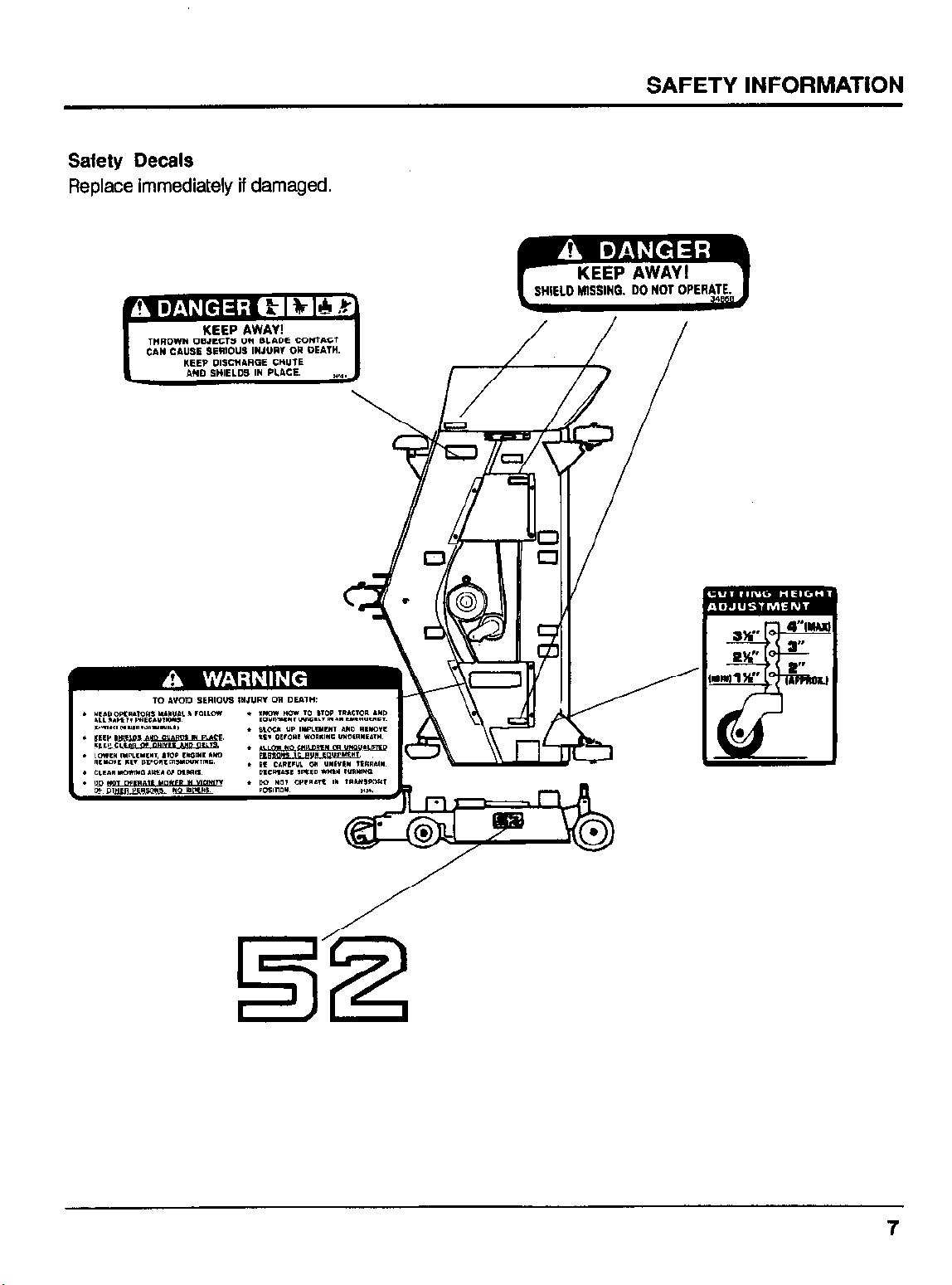
Safety Decals
Replace immediately if damaged.
SAFETY INFORMATION
THROWN OBJECTS OR BLADE CONTACT
CAN CAUSE SERIOUS INJURY OR DEATH.
*
KEEP AWAY!
KEEP DISCIIARQE CHUTE
AND SHIELDS IN PLACE.
,“~,
7
Page 9
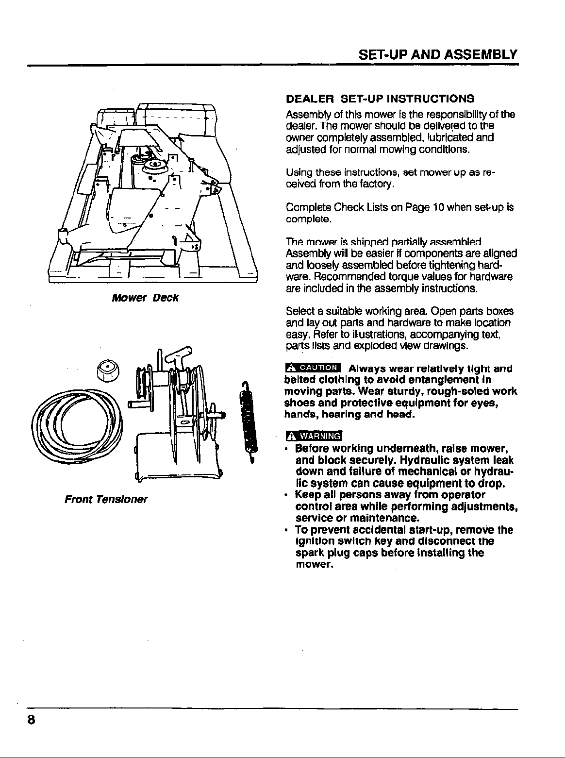
Mower Deck
SET-UP AND ASSEMBLY
DEALER SET-UP INSTRUCTIONS
Assembly of this mower is the responsibility of the
dealer. The mower should be delivered to the
owner completely assembled, lubricated and
adjusted for normal mowing conditions.
Using these instructions, set mower up as re-
ceived from the factory.
Complete Check Lists on Page 10 when set-up is
complete.
The mower is shipped partially assembled.
Assembly will be easier if components are aligned
and loosely assembled before tightening hardware. Recommended torque values for hardware
are included in the assembly instructions.
Select a suitable working area. Open parts boxes
and lay out parts and hardware to make location
easy. Refer to illustrations, accompanying text,
parts lists and exploded view drawings.
Front Tensioner
m Always wear relatively tight and
b$lted ckthlng to avoid entanglement In
moving parts. Wear sturdy, rough-soled work
shoes and protective equipment for eyes,
hands, hearing and head.
rklng underneath, raise mower,
and block securely. Hydraulic system leak
down and failure of mechanical or hydraulic system can cause equipment to drop.
l Keep all persons away from operator
control area while performing adjustments,
service or maintenance.
l To prevent accidental start-up, remove the
ignition switch key and disconnect the
spark plug caps before installing the
mower.
8
Page 10
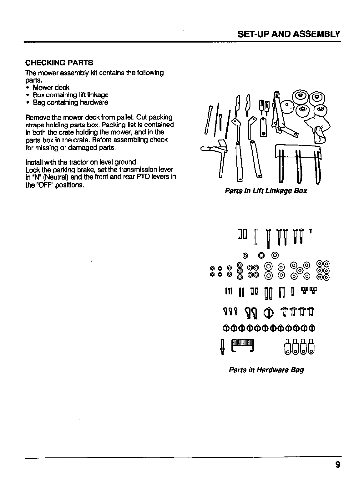
CHECKING PARTS
The mower assembly kit contains the following
p&S.
l Mower deck
l Box containing lift linkage
l Bag containing hardware
Remove the mower deck from pallet. Cut packing
straps holding parts box. Packing list is contained
in both the crate holding the mower, and in the
parts box in the crate. Before assembling check
for missing or damaged parts.
Install with the tractor on level ground.
Lock the parking brake, set the transmission lever
in “N” (Neutral) and the front and rear PTO levers in
the “OFF” positions.
Parts in Lift Linkage Box
Parts in Hardware Bag
9
Page 11
SET-UP AND ASSEMBLY
Pre-Delivery Check List
(Dealer Responsibility)
1. Inspect the mower thoroughly after assembly to
ensure it is set up properly before delivering it to
the customer. The following check lists are a
reminder of points to inspect. Check off each
item as it is found satisfactory or after proper
adjustment is made.
2. Check all bolts to be sure they are correctly
torqued .
3. Check that all linchpins are properly installed.
4. Lubricate all grease fittings; check to make sure
a small amount of grease comes out of seal.
5. Check that blades have been properly installed.
Delivery Check List
(Dealer Responsibility)
1. Check mower attitude and belt alignment.
2. Check that mower lift is properly adjusted. (See
Assembly instructions.)
3. Show customer how to make adjustments.
4. Explain importance of lubrication to customer
and point out lubrication points on mower.
5. Point out safety features, shielding and options.
6. Present the Operator’s Manual, and ask customer to become familiar with all sections.
Page 12
INSTALLING FRONT TENSIONER BRACKET
NOTE: Some tractors may already have pulley and
front tensioner guard installed. If not installed, the
front pulley, tensioner guard and front hitch pivots
come as spare parts with the tractor. Locate them
before beginning assembly. if already installed,
proceed to installation of front tensioner.
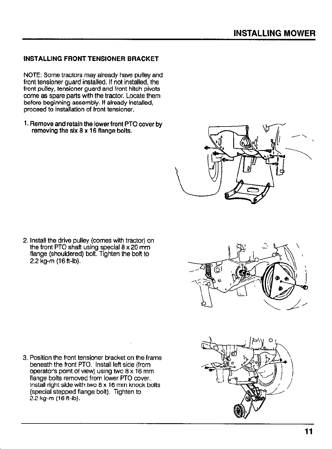
1. Remove and retain the lower front PTO cover by
removing the six 8 x 16 flange bolts.
2. Install the drive pulley (comes with tractor) on
the front PTO shaft using special 8 x 20 mm
flange (shouldered) bolt. Tighten the bolt to
2.2 kg-m (16 &lb).
3. Position the front tensloner bracket on the frame
beneath the front PTO. Install left side (from
operator’s point of view) using two 8 x 16 mm
flange bolts removed from lower PTO cover.
Install right side with two 8 x 16 mm knock bolts
(special stepped flange bolt). Tighten to
2.2 kg-m (16 ft-lb).
Page 13
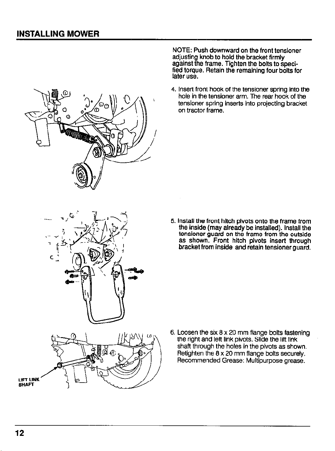
NOTE: Push downward on the front tensioner
adjusting knob to hold the bracket firmly
against the frame. Tighten the bolts to specified torque. Retain the remaining four bolts for
later use.
4. Insert front hook of the tensioner spring into the
hole in the tensioner arm. The rear hook of the
tensioner spring inserts into projecting bracket
on tractor frame.
LIFT LINK
SHAFT
5. install the front hitch pivots onto the frame from
the inside (may already be installed). install the
tensioner guard on the frame from the outside
as shown. Front hitch pivots insert through
bracket from inside and retain tensioner guard.
6. Loosen the six 8 x 20 mm flange bolts fastening
the right and left link pivots. Slide the lift link
shaft through the holes in the pivots as shown.
Retighten the 8 x 20 mm flange bolts securely.
Recommended Grease: Multipurpose grease.
12
Page 14
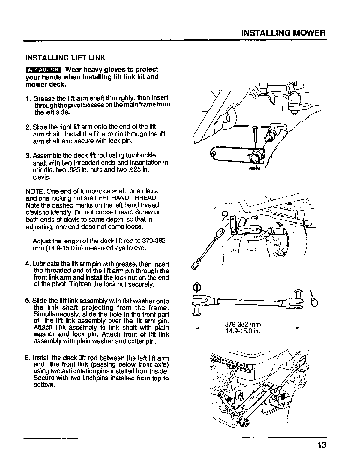
INSTALLING LIFT LINK
m Wear heavy gloves to protect
ybur’haids when installing lift link kit and
mower deck.
1, Grease the lift arm shaft thourghiy, then insert
through the pivot bosses on the main frame from
the left side.
2. Slide the right lift arm onto the end of the lift
arm shaft, Install the lift arm pin through the lift
arm shaft and secure with lock pin.
3. Assemble the deck lift rod using turnbuckle
shaft with two threaded ends and indentation in
middle, two ,625 in. nuts and two .625 in.
clevis.
NOTE: One end of turnbuckle shaft, one clevis
and one locking nut are LEFT HAND THREAD.
Note the dashed marks on the left hand thread
clevis to identify. Do not cross-thread. Screw on
both ends of cievis to same depth, so that in
adjusting, one end does not come loose.
INSTALLING MOWER
Adjust the length of the deck lift rod to 379-382
mm (149-l 5.0 in) measured eye to eye.
4. Lubricate the lift arm pin with grease, then insert
the threaded end of the lift arm pin through the
front link arm and install the lock nut on the end
of the pivot. Tighten the lock nut securely.
Slide the lift link assembly with flat washer onto
5.
the link shaft projecting from the frame.
Simultaneously, slide the hole in the front part
of the lift link assembly over the lift arm pin.
Attach link assembly to link shaft with plain
washer and lock pin. Attach front of lift link
assembly with plain washer and cotter pin.
6.
install the deck lift rod between the left lift arm
and the front link (passing below front axle)
using two anti-rotation pins installed from inside.
Et;:: with two linchpins installed from top to
.
Page 15
INSTALLING MOWER
ASSEMBLING MOWER DECK
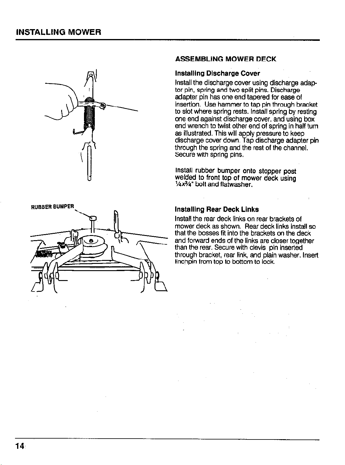
InstaDiing Discharge Cover
Install the discharge cover using discharge adaptor pin, spring and two split pins. Discharge
adapter pin has one end tapered for ease of
insertion. Use hammer to tao oin throuah bracket
to slot where spring rests. Install spring‘iby resting
one end against discharge cover, and using box
end wrench to twist other end of spring in half turn
as illustrated. This will apply pressure to keep
discharge cover down. Tap discharge adapter pin
through the spring and the rest of the channel.
Secure with spring pins.
install rubber bumper onto stopper post
welded to front top of mower deck using
1/4x3/4” bolt and fiatwasher.
RUBBER BUMPER
.,
installing Rear Deck Links
Install the rear deck links on rear brackets of
k
mower deck as shown. Rear deck links install so
that the bosses fit into the brackets on the deck
and forward ends of the links are closer together
than the rear. Secure with clevis pin inserted
through bracket, rear link, and plain washer. Insert
linchpin from top to bottom to lock.
14.
Page 16
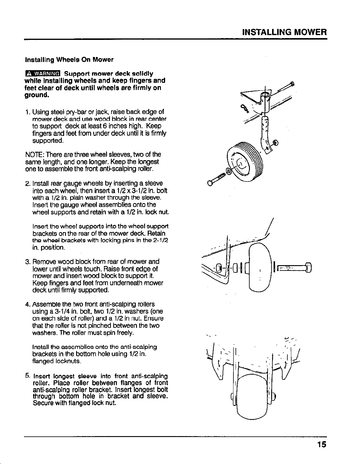
installing Wheels On Mower
, -
t
m Support mower deck solidly
while installing wheels and keep fingers and
feet clear of deck until wheels are firmly on
ground.
1, Using steel pry-bar or jack, raise back edge of
mower deck and use wood block in rear center
to support deck at least 6 inches high. Keep
fingers and feet from under deck until it is firmly
supported.
NOTE: There are three wheel sleeves, two of the
same length, and one longer. Keep the longest
one to assemble the front anti-scalping roller.
2. Install rear gauge wheels by inserting a sleeve
into each wheel, then insert a 112 x 3-l/2 in. bolt
with a 112 in. plain washei through the sleeve.
Insert the gauge wheel assemblies onto the
wheel supports and retain with a 112 in. lock nut.
INSTALLING MOWER
Insert the wheel supports into the wheel support
brackets on the rear of the mower deck. Retain
the wheel brackets with locking pins in the 2-112
in. position,
3. Remove wood block from rear of mower and
lower until wheels touch. Raise front edge of
mower and insert wood block to support it.
Keep fingers and feet from underneath mower
deck until firmly supported.
4. Assemble the two front anti-scalping rollers
using a 3-l/4 in. bolt, two l/2 in. washers (one
on each side of roller) and a l/2 in nut. Ensure
that the roller is not pinched between the two
washers. The roller must spin freely.
Install the assemblies onto the anti-scalping
brackets in the bottom hole using 112 in.
flanged locknuts.
5. insert longest sleeve into front anti-scalping
roller. Place roller between flanges of front
anti-scalping roller bracket. Insert longest bolt
through bottom hole in bracket and sleeve.
Secure with flanged lock nut.
15
Page 17

INSTALLING MOWER DECK
Positioning Mower Under Tractor
1. Connect the spark plug caps to the spark plugs
(if removed) and insert the ignition key in the
ignition switch. Check that the hydraulic ilft lever
is in NEUTRAL. Start the engine and move the
hydraulic cylinder selector lever (if installed) to
the FRONT position. Raise the lift arm fully with
the Lii Selector Lever.
2, Turn the Lowering Speed Adjusting knob fully
clockwise to lock the lift arm up. Stop the
engine. Remove the key from the engine switch
and disconnect the spark plug caps.
3.
Turn the steering wheel to the extreme left to
allow clearance for the mower deck. To avoid
obstructions, make sure rear deck links are I
forward, towards front of mower. Roil and push
the mower deck under the tractor from the right
side; return the steering wheel to the straightahead position.
4.
Return lift arms to down position to complete
hookup of mower. Turn the Lowering Speed
Adjusting knob fully counter-clockwise (“FAST
direction). Move the Lii Selector Lever to
“DOW, and push the front lift arm completely
down by hand.
NOTE: If arm does not move, Lowering Speed
Adjusting knob is not fully counter-clockwise. Turn
to release, then push down on lift arms as iilustrated.
16
Page 18

Attaching Rear Mower Deck Links
mm
1. Roil mower forward or backward or tug from
side to side as necessary to line up holes in rear
mower deck link with holes in bracket under
tractor. Bracket is difficult to recognize at first,
look for hole just behind the main mounting
bracket along centerline of tractor.
2. Grease the rear link shaft (long shaft with two
holes in either end for linchpins) then slide it
horizontally through the holes in rear deck links
and holes in the bracket as shown. Start by
hand, but it may be necessary to tap with
hammer to complete. Secure both sides with
iinchpins.
Attaching Front Deck Links To Mower
1. Turn the two clevis to adjust the length of the
front deck links to 280-282 mm (11.0-l 1 .l in)
measured from eye to eye, then tighten the lock
nut securely.
Ins&t Rear Link Shaft
2. Raise the front of the mower deck a few inches
with steel pry bar, block of wood or jack to align
the holes in the links and brackets.
3. Fasten front link to mower deck by inserting
cievis on projecting bracket on front of mower.
Secure by passing anti-rotation pin through
cievis and bracket and insert linchpin.
4. Fasten other end of front link to projecting
bracket on front of tractor, fiiing upper hole in
deck link over projecting stud on bracket.
Secure with iinchpin. Repeat for other side.
Remove support from front of mower deck.
(11.0-l 1 .l in)
:,
J
1’
r
Page 19

150-l 52 mm
5.9 - 6.0 in
Attaching Lift Plates
Screw mower deck lift plates into adjustable
pins as illustrated. Turn to adjust the length of
the-mower deck lift plates to 150-152 mm (5.9-
6.0 in), then tighten the nuts securely. Install the
mower deck lift plates on the mower deck with
5/8 in. plain washers and lock pins.
2.
Raise the right mower deck lift plate to the lift
arms installed earlier on the lift arm shaft assembly. Lift arms will be directly above the lift
plate. Maneuver the mower deck lift plate over
the projecting stud on the lift arm. Secure with
5/8 in. plain washer and lock pin. install the left
mower deck lift plate the same way.
18
Attaching Front Link Protector
Position the front link protector on link arms. Insert
clevis pin through hole in front link protector
bracket and front link from the inside. Secure with
l/2 in. plain washer and lock pin. Repeat for other
side.
Page 20

LEVELING MOWER DECK
1. Place the tractor on a firm, level surface and set
the parking brake. Make certain that tractor tires
are inflated to proper pressure. See Tractor
Owners Manual for information on inflation.
2. Check that the gauge rollers and front antiscalping rollers are set on 2.5 in. position (one
hole showing on wheel support). If not, raise the
mower deck with the Lift Selector lever set to
“UP”.
3. When lift arms are fully raised, turn the Lowering Speed Adjusting knob fully clockwise to lock
the deck in position.
4. Stop the engine and remove the key; adjust
wheels to the 2.5 in. position.
5. Return the Lowering Speed Adjusting knob to its
original position; lower the mower deck fully.
INSTALLING MOWER
m if the Lift Selector Lever is set to
“&VN’:the mower deck will automatically
lower to the ground as the Lowering Speed
Adjusting knob is turned counter-clockwise.
Keep clear of the deck.
19
Page 21

Front to Back Leveling
1. Set the left and right mower blades so that they
face front and rear. Measure the distance to the
ground from front and rear of blades.
NOTE: This measurement can be made with a
steel tape or by using the Blade Height Gauge, an
optional HONDA part (#07JPJ-75OOlOA) available at your HONDA Multipurpose Tractor Dealer.
With the gauge wheels set at the 2%”
position, and the two outside blades
positioned as shown, the blade height at
points A and B should be 64 - 70 mm (2.52 -
2.76 in). The blade height at points C and D
should be slightly higher by about 3 mm (.l
in). The blade height should be the same for
left and right blades.
2. If distance at front of blade tip is too great or
too small, adjust as follows: (Perform this
before connecting drive belt). Tip up front of
deck with steel pry bar and support front of
deck with wooden block.
3. Remove the linchpin and clevis pin from the
right and left front links. Loosen the nuts which
hold the clevis tight. Turn both cievis an equal
number of full turns so that both will be set at
same length.
NOTE: Turning the clevis “OUT” lowers the front
clearance; “IN” raises the clearance Each turn
changes height by just over 1 mm (l/32 in).
4. If right and left blade heights are not equal, add
or subtract turns to make equal.
5. After completing adjustment, tighten nut holding
clevis in place, reinsert clevis pin and secure
with linchpin
Page 22

INSTALLING DECK BELT
! .-
m Never attempt to than e drive
belts while the engine is running.
I?
emove
the ignition switch key from the ignition and
disconnect the spark plug caps to prevent
accidental start up.
Loosen the Belt Tension Adjusting knob fully.
1.
Place the V-belt on the PTO drive pulley, then
on the mower drive pulley as illustrated.
Push up on drive belt tensioner to ease instal-
2.
lation, then place the belt on the pulley on the
tensioner side (right). Next, place belt on the
pulley on the left side.
3. Position the V-belt drive stopper (comes
with tractor) onto the frame as shown using
one 10 x 20 flange bolt and one 8 x 16
flange bolt. Tighten bolts to 2.2 Kg-m (16
ft-lb).
INSTALLING MOWER
4. install the belt stopper collars on each side
of the tensioner frame using 8 x 45 mm
flange bolts. Tighten bolts to 2.2 Kg-m (16
ft-lb).
NOTE: Check that the belt is properly installed on
the pulley with a 90” twist between the drive
pulley and the idler pulley. Be sure the “V” of the
belt goes in the “V” of the pulley.
5. Reconnect spark plugs. Start the engine, move
the hydraulic cylinder selector lever (if so
equipped) to “FRONT’. Move Lift Sector lever
to “UP” and raise the mower deck fully.
NOTE: Deck must be in fully raised position to
properly set belt tension.
Turn the Lowering Speed Adjusting knob fully
6,
clockwise to prevent the deck from lowering.
7.
Stop the engine and remove the key from the
engine switch.
Adjust the Belt Tension Knob until the
8.
BELT ADJUST ST0
stopper of the tension arm just contacts the
frame as illustrated.
BELT STOPPER COLLAR
Return the Lowering Speed Adjusting knob
9.
the original position.
to
Page 23

INSTALLING MOWER
Adjusting Lifting Height With Lift Plate
1, Place the tractor on a firm, level surface. Apply
and lock the parking brake.
2. Start the engine, move the Hydraulic Cylinder
Selector Lever (if installed) to FRONT. Set Lift
Selector lever to “UP” and raise the mower deck
fully.
3. When mower is fully raised, turn the Lowering
Speed Adjusting knob fully clockwise to lock
hydraulic system.
4. Stop the engine and remove the key from the
ignition switch.
If the Lift Selector Lever is set to
“DOWN” the mower deck will automatically
lower to the ground as the Lowering Speed
Adjusting knob is turned counterclockwise.
Keep clear of the deck.
Set a wood block under the deck to hold it 4 or
5.
more inches off the ground, if it should descend. Measure from mower deck to ground. If
measurement is less than 109 mm (4.3 in)
shorten the mower deck lift plates to raise the
deck higher. When raised to the maximum
position, the mower should be 109-l 13 mm
(4.3-4.5 in) off the ground. Measure both sides
to be sure they are equal.
If shortening the mower deck lift plates is
6.
necessary, lower deck by moving Lift Selector
Lever to “DOWN”. Mower will descend as the
Lowering Speed Adjusting knob is turned
counterclockwise.
Remove lock pin holding lift plate onto stud on
7.
lift arm. Pull the lift plate towards you. This will
free lift plate so that it can turn to adjust. Screw
the lift plate in to shorten it, which will increase
the mower deck lift height. [Each turn will
shorten by about 3 mm]. Shorten or lengthen
the plates as necessary to make both sides
equal.
22
6.
After adjusting length of lift plates, replace plate
on stud, and lock with lock pin. Start engine,
raise mower, turn Lowering Speed Adjusting
knob fully clockwise to lock and repeat adjust-
ment. If deck cannot be raised to 109 mm, see
next section on adjusting lift rod.
Page 24

Mower Deck Lift Rod
1, If the height of the mower deck is less than 109
mm (4.3 in), adjust the mower deck lift rod until
the height is between 109 to 113 mm (4.3 to 4.5
in). The mower deck lift rod is adjusted as
follows: With deck in the lowered position, back
off on lock nuts on lift rod. Rod is designed as a
turnbuckle. Use a wrench on the flats of the rod
to turn it.
2. Turn the rod clockwise to tighten, thus increasing the lift height of the deck. Turn it counter-
clockwise to loosen. After adjustment, tighten
the lock nuts securely.
3. Do not shorten the mower deck lift rod to less
than 379 mm (14.9 in) when first adjusting deck.
If the height of the mower blade is below
109 mm (4.3 in) when the mower deck lift rod is
379 mm (14.9 in) long, first use the mower deck
lift plates to adjust the deck height.
INSTALLING MOWER
4. If the mower cannot be raised to 109 mm (4.3
in) using the deck lift plates, then adjust the
length of the mower deck lift rod.
23
Page 25

INSTALLING MOWER
Lift Link Rod
1. Check that the distance between the end of the
rod and the bottom washer is 27-29 mm
(1.0-l .l in).
2. To adjust, loosen the lock nut and turn the
adjusting nut. After adjustment, retighten the
lock nut securely.
24
Page 26

DETACHING MOWER
1. Start the engine and move the Hydraulic Cylinder Control lever (if installed) to “FRONT’. Move
Lii Selector Lever to “UP”. Stop engine and
remove key and disconnect spark plugs.
2. Set gauge wheel at rear to l-1/2 in. and lower
the deck.
3. Start engine and lower deck. Stop engine,
remove key, disconnect spark plugs.
4. Remove mower deck drive belt from driven
pulley on deck by removing front tensioner belt
stopper, belt stopper collar, and loosening
front tensioner adjusting knob. Remove belt
from front tensioner to create slack for driven
pulley. (Sea Maintenance section for detailed
description.)
5. Remove lock pins holding front deck lift plates
and slip lift plates off projecting stud on tractor
frame.
6. Remove belt guard.
Removb lock pins
25
Page 27

7. Use steel pry bar or jack to raise front of deck
slightly. Pull linchpins holding front deck links to
projecting bracket on deck. Lower deck to
ground..
8. Pull lock pin holding rear deck links to rear deck
link shaft. Use drift pin to tap out rear deck link
shaft. Lower rear deck links to deck as shaft is
withdrawn.
26
Remove linchpins and link shaft
9. Turn steering wheel to extreme left. Pull mower
deck from right side of tractor.
Page 28

For safe and efficient mowing, always make a pre-
operation inspection before starting:
Inspect the tractor on level ground.
Set the parking brake, put the transmission lever in
“N” (NEUTRAL) and PTO clutch lever in the “OFF”
and the lift lever in the center (NEUTRAL) positions. Disconnect the spark plug cap and remove
the key to prevent accidental engine start-up.
Never run the engine in an
enclosed area. Be sure to provide adequate
ventilation. Exhaust contains poisonous
carbon monoxide gas that may cause loss of
consciousness and lead to death.
CLEANING MOWER DECK (EXTERIOR)
1, Check that the mower deck is lowered fully.
2. Remove grass and other foreign matter from the
mower deck.
DECK DRIVE BELT
Lower the mower deck fully, remove the ignition
key and disconnect the spark plug caps. Visually
inspect the drive belt for wear, cracks or other
faults, if the drive belt is faulty, follow the replacement procedure described on Page 39.
27
Page 29

PRE-OPERATION CHECKS
CHECKING BLADE CONDITION
Before each use, check each mower blade for
damage or abnormal wear.
1. Stan the engine and set Hydraulic Cylinder
Selector lever (ii installed) to “FRONT”. Raise the
mower deck fully with the Lii Selector lever.
Turn the Lowering Speed Control knob fully
clockwise to prevent descent. Do not over-
tighten the knob.
9 1.
m Severe personal injury can
result if a piece of blade breaks off and is
thrown from under the mower deck.
.
Never operate the tractor with a worn or
damaged blade.
.
Never operate the tractor with a blade that
is cracked or notched at the base of its
upturned edge.
Push the Lii Selector lever toward “DOWN” to
2,
be sure that the mower deck is locked in the
fully raised position. Mower should not descend.
3. Set Lii Selector lever back to “NEUTRAL”.
9 a-
m To avoid personal injury:
l Remove the ignition key to prevent acci-
dental starting.
l Wear heavy gloves to protect your hands
from the mower blades.
l Place a block under the mower deck to
prevent it from lowering unexpectedly.
l Stop the engine, remove the ignition key
and disconnect the spark plug caps.
4. inspect each of the blades for cracks, bending
or signs of wear. The right and center blades
can be seen from under the right side of the
mower deck . The left blade can be seen from
under the left front edge of the mower deck.
Turn the blades 180” to inspect the opposite
side.
28
Page 30

If any of the blades show signs of damage or
excessive wear, a more thorough inspection is
necessary (see Page 25 for Mower Deck Removal). A dull blade can be sharpened, but a
blade that is worn out, bent, cracked or otherwise
damaged must be replaced. If a blade needs
sharpening or replacement, take the mower deck
to your authorized HONDA Multipurpose tractor
dealer. Or if you have the proper tools, you can
remove and install the blade yourself.
Use a genuine HONDA replacement blade
or equivalent.
To reduce the possibiiity of weakening the
blade or causing imbalance or poor cutting
performance, sharpening should be per-
formed by an authorized HONDA Muiti-
purpose Tractor dealer.
5. When you have completed the blade inspection, return the Lowering Speed Adjust knob to
its original position.
PRE-OPERATION CHECKS
NORMAL
EXCESSIVELY
WORN
CRACKED
m if the Lift Selector Lever is set to
**LO\;JN*‘the mower deck will automatically
lower to the ground as the Lowering Speed
Adjusting knob is turned counterclockwise.
Keep clear of the deck.
29
Page 31

ADJUSTING CUTTING HEIGHT
1. Park the tractor on a level surface and set the
parking brake.
2. Make sure the Main Transmission Lever is in
“NEUTRAL” and the PTO levers are “OFF” and
the lift lever is in the center (NEUTRAL) position.
3. Start the engine, move the hydraulic cylinder
selector lever (if installed) to “FRONT” and raise
the mower deck fully with the Lift Selector lever.
4. Turn the Lowering Speed Adjust knob fully
clockwise to lock the hydraulic system.
5. Set the Lift Selector lever to “DOWN” to be sure
the mower deck is locked in the fully raised
position. Deck should not descend. Return the
lift lever to “NEUTRAL” and then stop the engine
and remove the ignition key.
A -
t
m Be sure all moving parts have
stopped before adjusting cutting height.
Contacting moving parts can cause injury.
6. Remove the locking ,pin from the gauge wheel
and set the wheel for the desired cutting height.
7. Repeat the adjustment procedure for the other
gauge wheel.
NOTE: Both gauge wheels must be set to the
same height.
8. If necessary, remove the nut and bolt from left,
right and center anti-scalping rollers, and set
the anti-scalp rollers for the desired cutting
height. This height is determined by which hole
is used in anti-scalping wheel brackets. As
illustrated, top hole sets height of 1.5 in, middle
hole 2 in and bottom hole 2 l/2 in. Make sure to
set all anti-scalping rollers to same height.
9. Insert the bolt into the anti-scalp roller bracket
and secure it with the nut.
30
Page 32

LOWERING SPEED ADJUSTMENT
1. Adjust how quickly the deck descends by
turning the Lowering Speed Adjusting knob.
Adjustment is normal if it takes l-2 seconds for
the mower deck to lower from the highest
position to the ground.
2, Turning the knob clockwise toward “SLOW’ will
decrease the speed, and turning it counterclockwise toward “FAST” will increase the
speed.
NOTE: Uneven mowing may result if the descent
speed is too slow.
OPERATION
31
Page 33

OPERATION
STARTING
1. Start the engine. With parking brake set,
depress the clutch pedal and place the main
and auxiliary transmission levers in the desired
gear range for mowing.
2. Lower the mower deck and advance throttle to
increase engine speed. Always mow at full
throttle for best Ft quality.
3. Depress the brake pedal and release the
parking brake lock lever.
4. Slowly move the front PTO lever to “ON”
position. The mower blades will start to
rotate.
STOPPING
in An Emergency
1, Turn the engine switch to “OFF”.
2. Depress clutch and brake pedal.
In Normal Use
I. Move throttle to “SLOW”.
Depress clutch and brake pedals
simultaneously
Move Main Transmission lever to
“NEUTRAL”.
2. Shift PTO lever to “OFF” position.
3. Turn engine switch to “OFF”. Remove key from
ignition.
4. Press down on Parking Brake Lock Lever while
depressing brake pedal to set parking brake.
MOWING
Before operating this tractor you should read and
understand the Safety Information on Pages 4-6.
When mowing tall grass, make a first pass with the
deck fully raised. This will help to expose any
hidden obstacles. When you are sure that the area
is completely cleared, mow again at the desired
height.
m] if the tractor should accidentally
get caught on an unseen object (rock, root,
hole, etc.), do not attempt to ride over the
obstruction or turn the steering wheel to free
the mower. These actions can damage the
steering mechanism or the deck.
Mowing Tips
1. Mow at full throttle for best cut quality. The lawn
may not be trimmed uniformly at medium or low
engine speeds.
2. Observe the following when mowing:
4th gear
5/6th gear Normal cutting
7th gear Light cutting or transporting
8th gear
3. If grass is exceptionally tall, set deck to highest
position on first pass, then mow again with
deck set to desired height. Also allow the lawn
to dry thoroughly before you use the mower. To
cut a thick or lush lawn, mow in a lower gear or
cut twice.
4. Always turn counter-clockwise at low ground
speed when cutting close to trees, posts,
sprinklers, wails, etc.
5. Y&J may cut the lawn too short when the lawn is
thick or wet, and/or the ground is soft as the
gauge wheels may sink into soft ground.
Heavy cutting or trimming
Use only for transporting
32
6. Increase the cutting height if the lawn is spindly
and the surface is uneven.
Page 34

CUTTING PATTERNS
These cutting patterns are only recommended for
a flat, level lawn surface.
In a small area
First make 2 or 3 turns in a clockwise direction.
Then turn around and continue cutting in the
reverse direction.
In a large area
The first round of cuts is the key to making a neat
finish. First, make 2 or 3 turns in a clockwise
direction, As you reach the center of the area, turn
to the right and continue cutting in the reversa
direction until you have finished the upper half of
the area. Cut the grass in the remaining half in a
counter-clockwise direction.
OPERATION
Small Area Cuffing Pattern
Mowing unsquars areas
If your mowing area is not square or four-sided,
divide the area into several blocks so you can
mow In a neat mowing pattern.
Overlapping on straightaways
Be sure that each mowing lane overlaps sufficiently. The recommended overlap width is between 4-6 inches or approximately the width of
one of the mower’s front tires.
Overlapping in curves and turns
When cutting in curves and turns, shift to a slower
speed and be sure to overlap the previous cut by
20-50% or approximately half the width of the
mower.
Large Area Cutting Pattern
33
Page 35

LUBRICATION INFOFiMATlON
1. Do not let grease or oil collect on or around
parts, particularly when operating in sandy
areas.
2 The accompanying illustration shows lubrication
points. The’chart gives the frequency of lubrica-
tion in ‘operating hours, based on normal
operating conditions. Severe or unusual conditions may require more frequent lubrication.
Some reference numbers have more than one
location; be sure you lubricate all locations,
3. In addition to the lubrication points shown, at
least once a year, oil the mower lift pivot points,
Lubrication Points
Ref. No. Item Description Frequency
1. Rear Gauge Wheel Shaft
8 hrs
Item Operation
Each Use First 20 Hrs Every 50 Hrs Refer To Page
4. Use a good quality SAE Multipurpose grade
grease at grease fiiing locations. Be sure to
clean fiiings thoroughly before attaching
grease gun.
5. Use SAE 30W oil in areas without grease
fiiings.
Maintenance Schedule
Periodic maintenance and adjustment are necessary to keep the tractor in good operating condition. Service and inspect according to the Maintenance Schedule.
Service Period
Mower Deck Exterior
Deck Drive Belt
Blade Condition
Blade Bolt Tightness
Blade Belt
Mower Deck (inside)
34
Clean
Check
Check
Check
Check
Clean
ii
X
X,
27,41
27,39
28,36
38
ii
X
40
Ad
Page 36

Weekly Check
1. Check all nuts and fasteners for tightness.
2. Note any joints or lubrication points needing
grease. Pay special attention to blade spindles,
the rear deck lift joints and the rear gauge
wheels. Use SAE Multi-purpose grade grease.
m To avoid carbon monoxide
pbisdning , shut off the engine before performing any maintenance. If you run the
engine in an area that is confined, or even
partially enclosed, the air you breathe will
contain a dangerous amount of exhaust gas.
If the engine must be run for any reason, be
sure the area is well ventilated.
l To avoid serious burns, allow engine to
cool before performing maintenance
MAINTENANCE
l Shut off engine and set the parking brake
before performing any maintenance.
. To prevent accidental start-up, remove the
ignition switch key and disconnect the
spark plug caps.
l The tractor and mower should be serviced
by an authorized HONDA multipurpose
tractor dealer unless the owner has proper
tools, service data and is mechanically
inclined.
35
Page 37

MAINTENANCE
BLADE SERVICING
Inspect blades for condition and proper installa-
tion.each time before operation. Replace any
blade that is bent, excessively nicked, worn or
has any other damage. Small nicks can be
ground out when sharpening.
Blade Removal
1.
Always wear heavy gloves when working near
the blade. Secure the movement of the blade
with a block of wood.
2.
Remove the special Nylock blade bolt (RIGHT
HAND THREADS). Remove the cup washers,
5/8” flat washer and blade. The shoulder washer
normally does not come off unless intentionally
removed.
1. Blade
2. Shoulder washer
3. Left belt shield
4. S/8” Standard flat washer
5. Cup washers
6. Blade bolt, special Nylock (right hand threads)
Blade Assembly
&
6
Blade Installation
1. Install the shoulder washer (if removed).
Check the orientation of the blade and make
2.
sure the cutting edge is positioned to lead in a
clockwise rotation, as viewed from the top of the
mower.
Inspect the condition of the cup washers.
3.
Replace the cup washers if they appeared
burned or flat.
v *
m Use a new Nylok blade bolt
when you replace the blade. Do not substitute any other bolt for the special blade bolt.
It Is self-locking, meeting the non-loosening
requirements for this application.
4. Install two cup washers on bolt. Install washer
and blade on bolt. Remember bolt has right
hand threads; install bolt and blade assembly
into spindle. Torque bolt to 23.5 kg/m (170 ft/
Ibs).
.
36
Page 38

Sharpening Blades
1, Remove blades.
MAINTENANCE
MAINTAIN CORNER
2. Always sharpen both ends equally to maintain
balance. Follow original sharpening pattern. Do
not sharpen blade to a razor edge. Leave from
l/32 in. to l/16 in. blunt edge. Do not sharpen
back side.
-1 When sharpening blades be sure
to balance them. Unbalanced blades will
cause excessive vibration which can damage
blade spindle bearings. Vibration may also
cause structural cracks in mower compo-
nents.
1, Test balance by placing the clean, sharpened
blade on a screwdriver. A balanced blade will
stay horizontal. If one end of the blade dips,
grind or file the heavy end until good balance is
achieved.
BLADE INSPECTION
Before each use, check each mower blade for
damage or abnormal wear.
1. Start the engine and raise the mower deck fully
with the Lii Control Lever set to “UP”. Turn the
Lowering Speed Control knob fully clockwise to
prevent descent. Do not overtighten the knob.
FOLLOW ORIGINAL
Blade Sharpening
NORMAL ‘Ty
BENT D
2. Stop the engine and remove the ignition key.
Block deck with wood block to prevent lowering.
3. Inspect each of the blades for cracks, bending
or signs of wear. The right and center blades
can be seen under the right side of the mower
deck, The left blade can be seen from under
the left front edge of the mower deck. Turn the
blades 180“ to inspect the opposite side.
.
Severe personal injury can result if a piece
of blade breaks off and is thrown from
under the mower deck.
l Never operate the tractor with a worn or
damaged blade.
.
Never operate the tractor with a blade that
is cracked or notched at the base of its
upturned edge.
x CRACKEO
Blade Condition
37
Page 39

MAINTENANCE
1.
2. Shoulder washer -’ 6
3. Left belt shield
4. 5/8 in. standard flat washer
5. Cup washers
6. Blade bolt, special Nylok (right hand threads)
&
Blade Installation
1.
Install shoulder washer (if removed) small end
up. Make sure blade cutting edge is positioned
to lead in clockwise rotation, as viewed from top
of mower.
2.
Excessive blade slippage can cause cup
washers to burn and lose their clamping force.
Inspect cup washers to determine if they are
burned or have lost their clamping force. Replace as necessary.
mend you install a new Nylok
blade bolt when you replace the blade.
. Do not substitute just any bolt for the
special blade bolt. It is self-locking, meet-
ing the non-loosening requirements for
this application.
3. Install two cup washers on bolt,
4. Install washer and blade on bolt.
5. Install bolt and blade assembly in to spindle.
Blade Assembly
, ,
m Your dealer can supply genuine
HONDA replacement blades. They are made
of special steel alloys and subjected to rigid
heat-treat and inspection requirements.
Substitute blades may not meet these rigid
specifications and MAY BE ,DANGEROUS.
6. Torque bolt to 23.4 kg-m (170 ft-lbs).
0
38
Page 40

SPINDLE REPAIR
Blade Spindle Removal
1. Remove blade from spindle.
2. Remove belt shield.
MAINTENANCE
3. Remove belt from pulleys.
4. Remove bolt and flat washer from top of spindle
shaft.
5. Disassemble split taper bushing (located on top
of pulley) by removing the two bolts and inserting them into the threaded holes in bushing
flange. Tighten bolts alternately to remove split
taper bushing. Remove pulley.
6. Remove three bolts attaching spindle to mower
frame and remove spindle.
Spindle Repair Tips
1. As a reference point, the top of spindle housing
is the short portion.
2. To minimize wear, bearing cups, cones and
sleeves are press fit to shaft and will require a
press or similar device for removal.
3. When disassembling, support housing casting
to prevent damage.
4. Remove bearing cups by placing a punch in
housing slots and drive cup out. Alternate
punch positions from side to side. Use care to
prevent housing damage.
5. Bore-tite” sealant is used on the outer diameter
of the seals, Substitute seals may not meet
original equipment specifications and could
cause leakage.
Bore-Me Is a registered trademark of Chicago Rawhide Industries.
1. Spindle assembly
2. Seal
3. Sleeve
4. Bearing
5. Housing and cups
6. Cup
7. Shaft
cone
Spindle Assembly
I
c 1
39
Page 41

MAINTENANCE
Blade Spindle Disassembly
1. Support spindle in a press and push shaft
down through housing.
2. Remove seals from housing.
3. Remove bearing cups from housing as described in Spindle Repair Tips section.
4. Remove bearing cone from shaft.
5-
1. Spindle
2. Seal
3. Sleeve
4. Bearing
5. Housing and cups
6. Cup
7. Shaft
assembly
cone
-1
40
Spindle Assembly
Page 42

Blade Spindle Assembly
1, Bearing cups and cones are designed to work
together. It is important to position them so
bearing cone taper mates with bearing cup
taper.
2. Lubricate new cups with a light oil. Place them
in spindle housing so they will mate with cones.
Seat cups against machined shoulder of housing with a press or by placing a large drift on the
flat lip and driving them into housing.
3. Place bottom bearing cone onto spindle shaft
with taper up, Seat on bottom shoulder of shaft
with a press.
4. Insert shaft and bearing cone assembly through
bottom of housing. Fill housing cavity with a
lithium grease of #2 consistency with a MOLY
(molybdenum disulfide) additive.
5. Place top bearing cone on shaft to mate with
top bearing cup.
MAINTENANCE
7
I
5
1-1 Bearing adjustment is set by
pressing sleeve against bearing cone until
proper adjustment is attained.
6. Install sleeve on shaft and press sleeve and
bearing cone onto shaft until all bearing free
play is removed and there is a slight drag
(similar to adjusting the front wheel bearings on
an automobile). Check by spinning spindle. It
should turn freely.
6. Be careful not to over-tighten bearings. Proper
bearing adjustment is essential to good bearing
life.
7. Should you over-tighten bearings, hold spindle
housing and rap spindle shaft with a lead
hammer to loosen bearings, Readjust bearings
until proper setting is obtained.
-1 Improper positioning of seals
can cause seal failure.
8. Proper seal installation is important. An improp-
erly installed seal will leak and could cause
bearing failure.
@
1. Soindle assemblv e.
2. seal
3. Sleeve
4. Bearing cone
5. Housing and cups
6. Cup
7. Shaft
Spindle Assembly
s
1’
9.Pull the rubber portion of seal back and locate
spring.
41
Page 43

MAINTENANCE
I
2-
49 -3
----+\
lO.Apply a thin coat of lubricant to bottom seal (2)
and install with spring up toward center of
housing.
11 *Place bottom seal, squarely on housing. Select
a piece of pipe or tubing with an OD that will set
on outside edge of seal. A tube that is too small
will bow seal cage.
12Carefully press seal into housing, preventing
distortion to ‘metal seal cage. Seal should seat
firmly and squarely against machined shoulder
in housing.
13.Make sure seal lip did not roll under. Distortion
to seal cage or damage to seal lip will cause
seal. to leak. Damaged seals must be replaced.
14.Apply a thin coat of lubricant to top seal (2) and
install with spring up away from center of
housing. Top seal should be flush with top of
housing.
1, Spindle assembly
2. Seal
3. Sleeve
4. Bearing cone
5. Housing and cups
6. Cup
7. Shaft
Spindle Assembly
15Lubricate spindle with a lithium grease of #2
consistency with a MOLY (molybdenum disulfide) additive. Vent top seal with a blunt edged
tool such as a letter opener while filling with
grease. Rotate housing on spindle shaft,
checking for free movement.
Blade Spindle Installation
1. Insert spindle through bottom of mower deck
and install three mounting bolts, Be sure to
position grease fittings toward lubrication
access areas. Refer to lubrication chart.
I Pullev installation seauence is
very important fof bearing life. Follow the
sequence exactly.
2. Install pulley and split taper bushing with integral key on spindle shaft. Install bolt and flat
washer in top of spindle shaft. Torque this bolt
to 1.7 kg/cm (12 ft/lbs), then alternately tighten
split taper bushing bolts to 1.7 kg/cm (12 ft/lbs).
42
Page 44

REPLACING THE BELTS
One of the major causes of belt failure is improper
installation. Before a new belt is installed, check
pulley shafts and bearings for wear. Check pulley
grooves for cleanliness. Make sure spindles turn
freely and without wobble. If grooves require
cleaning, moisten a cloth with a non-flammable,
non-toxic degreasing agent or commercial detergent and water.
Avoid excessive force during installation. Do not
use tools to pry belt into pulley groove. Do not roll
belt over pulleys to install. This can cause hidden
damage and premature belt failure.
Drive Belt Replacement
1, Set the rear gauge wheel to 1 -l/2 in. position
(see Wheel Adjustments). Turn Lowering Speed
Adjusting knob counter-clockwise towards
“FAST’ and lower deck.
t accidental start-up, remove the
ignition switch key and disconnect the
spark plug caps before installing the
mower.
Wear gloves when installing belt. Be care-
ful. Do not allow your fingers to be caught
between belt and pulley.
Use care when installing or removing belt
from spring-loaded idler. Springs store
energy when extended and, if released
suddenly, can cause personal injury.
I. Remove belt stopper from front tensioning
guide, and belt stopper collars and two bolts
10 mm x 20 mm and 8 x 16 mm flange bolt
3. Turning counterclockwise, loosen the belt
tension adjust knob fully. Push up on the left
tensioner pulley to gain some slack in the belt.
Pull belt off left side pulley and remove it from
remaining pulleys starting with the one on the
opposite side.
4. Installation sequence is the reverse of disas-
sembly. After installing, check that belt is fully
seated in V-groves of pulley.
5. Adjust the amount of slack in the belt as described on Page 21 I
43
Page 45

MAINTENANCE
Pulley covera
siomr srm Idler pulley
Blade Belt Replacement
1.
Remove the mower deck from the tractor.
2.
Remove the four 5/16 in. nuts holding down the
left and right mower pulley covers. Clean out
any grass or debris.
3.
Check the belt for wear or cracks.
4.
If necessary to replace the belt, grasp it midway
between the right and left deck pulleys. As you
face the deck from the REAR, pull the belt
towards you and to the left. This will create
slack in the belt as the tensioner pulley moves.
With the slack you have created, slip the belt off
the left deck pulley. Next remove belt from right
pulley.
5.
Pull back on tensioner arm to release pressure
on tensioner arm spring. Unhook and remove
tensioner arm spring. Remove the spring pin
holding the tensioner arm to mower deck. Lii
arm and remove, allowing belt to slip free.
Pull here
6; Slip V-belt off remaining pulleys.
7. Install new V-belt in the reverse order of removal. Start with the driven pulley in center of
deck, then install tensioner arm, washer, felt
seal and spring pin. install tensioner arm spring,
then pass V-belt over left pulley and right pulley.
*
m If the belt Is not released slowly,
the ic&r pulley will move suddenly and could
injure your hand. Be sure to reinstall right
and left pulley covers after changing belt.
Failure to use pulley covers can cause serl-
ous personal injury.
8. Reinstall mower pulley covers using the four
5/l 6 in. nuts removed earlier.
44
Page 46

CLEANING MOWER DECK
1. Remove the mower from the tractor.
2. Remove the four 5/16 in. nuts holding down the
pulley covers and remove the left and right
pulley covers.
3. Remove grass and other foreign matter from
inside the covers.
4. Using a jack or other lifting mechanism, raise
deck a foot or more off the ground. Place two
wooden blocks in front and support deck firmly.
Clean off accumulated grass and other debris,
making sure to keep fingers away from blades.
NOTICE Do not use water or hose to clean
!iGJ
blade spindle bearings will cause premature
wear. Wait until bearings have cooled.
5. Install the mower back on the tractor.
NOTE: After pushing deck under tractor and
before installing, make sure that lift arms are all the
way down. Put Lift Selector Lever in Down position
and turn Lowering speed Adjustment Knob to
“FAST”, then pull arms down by hand to test.
ck just after mowing. Water on hot
45
Page 47

STORAGE
STORAGE
1, Remove the mower deck from the tractor.
2. Turn the mower deck upside down. Clean the
underside of the deck with water and dry
thoroughly.
3. For longer service and greater efficiency, keep
the underside of the mower housing clean and
free of accumulated grass clippings by washing
it down with a hose after use and/or cleaning it
with a wire brush and scraper, Remove any rust
and apply a rust-resistant paint. Cleaning and
rust prevention are especially important before
seasonal storage.
m Washing the deck directly after
use can cause premature bearing wear.
Allow the deck to cool before washing, then
run the deck to remove any excess moisture.
46
Page 48

TROUBLESHOOTING
PROBLEM
1. Mower overloading; material too tall or heavy
2. Oil on belt from over-lubrication
3. Belt hung up or rubbing
4. Belt or pulleys worn out
1. Belt misaligned or rubbing guide
1. Damaged belt
2. Worn pulley groove
SOLUTION
1. Reduce tractor speed but operate at full throttle.
Cut material twice: one high pass, then mow at
desired height, Cut a partial swath.
2. Be careful not to over-lubricate. Clean lubricant
from belt and pulleys with clean rag. Replace
oil-soaked belt.
3. Check belt for free travel in pulleys and belt
guides. Check under mower and around blade
spindle shafts for wire, rags or other foreign material. Clean all material from under mower.
4. If belt rides in bottom of pulley groove, either
belt or pulley is worn and must be replaced.
1. Re-align belt or guide. Be sure belt doesn’t rub
any other part while running.
1. Lay belt flat on floor. If belt does not lie flat (has
humps or twists), indicating broken or stretched
cords, it must be replaced.
2. Replace pulley.
1. Roll-over, high shock loads or installation
damage
1. High shock loads
2. Belt came off drive
1. Replace belt.
1. Avoid abusive mowing. Avoid hitting the ground
or obstructions.
2. Check drive alignment for foreign material in
grooves. Avoid hitting solid objects or ground.
47
Page 49

TROUBLESHOOTING
PROBLEM
1. Tractor speed too fast
2. Grass accumulation inside deck
3. Dull Blade
4. Tires improperly inflated
5. Mower not level
6. Wrong mower deck height
7. Engine speed too low
1. Blade drive belt worn or broken
2. PTO lever cable faulty or out of adjustment
3. Faulty PTO
1. Wrong blades
2. Deck too low
3. Engine overloaded
4. Lawn wet or watered
5. Lawn too tall
6. Engine speed too low
SOLUTlON
1. Shift to lower gear.
2. Clean deck underside.
3. Have the blades sharpened or replaced.
4. Check the tire inflation.
5. Level or see authorized HONDA Multi-purpose
Tractor dealer.
6. Change to proper height.
7. Run at full throttle.
1. Replace with new belt.
2. See your authorized HONDA multi-purpose
tractor dealer.
3. See your authorized HONDA multi-purpose
tractor dealer.
1. Use genuine HONDA blades or equivalent.
2. Raise deck and adjust deck height properly.
3. Operate at full throttle. Use lower speed range.
Set mower deck higher than desired height for
first pass, then cut to desired height on second
pass.
4. Allow to dry before cutting.
5. Set mower deck higher than desired height for
first pass, then cut to desired height on second
pass.
6. Run at full throttle.
1. Cutting height too low
2. Tractor speed too high
3. Uneven surface
4. Rough and uneven surface
1. Unbalanced blades
2. Drive/blade belt damaged
3. Pulley(s) damaged or out of alignment
1. Engine speed too low
2. Tractor speed too fast
3. Pebbles or other foreign matter are stuck
in mower deck
48
1. Increase to proper height.
2. Lower to proper speed.
3. Change cutting pattern.
4. Adjust with height adjuster.
1. Balance.
2. Replace.
3. See your authorized HONDA multi-purpose
tractor dealer.
1. Run at full throttle.
2. Shift to lower gear.
3. Remove.
Page 50

SPECIFICATIONS
1 Model
1 Overall length
verall width
ro---
Mowing width
Weight (including link)
Cutting height range
Number of blades
Blade length
Left and center blade speed
Right blade speed
Gauge wheels
Deck lifting/lowering
Deck mounting
MM52
1050 mm (41.3 in)
1675 mm (66 in)
1320 mm (52 in)
120 kg (266 Ibs)
1 -l/2 in. to 4 in.
3
456 mm (18 in)
3355 t-pm
3700 rpm
(2) 152.4 mm (6 in) diameter
Hydraulic
4 point linkage
I
49
Page 51

WARRANTY SERVICE
OWNER SATISFACTION
Your satisfaction and goodwill are important to your dealer and to us. All HONDA warranty details are
explained in the Distributor’s Limited Warranty. Normally, any problems concerning the product will be
handled by your dealer’s service department. If you have a warranty problem that has not been handled to
your satisfaction, we suggest you take the following action:
l Discuss your problem with a member of dealership management. Often complaints can be quickly
resolved at that level. If the problem has already been reviewed with the Service Manager, contact the
owner of the dealership or the General Manager.
l If your problem still has not been resolved to your satisfaction, contact the Power Equipment Customer
Service Department of American Honda Motor Co., Inc.
AMERICAN HONDA MOTOR CO., INC.
Power Equipment Customer Service Dept.
Duluth, Georgia30136-9421
Telephone: (404) 497-6400
We will need the following information in order to assist you:
- Your name, address and telephone number
- Product model and serial number
- Date of purchase
- Dealer name and address
- Nature of problem
After reviewing all the facts involved, you will be advised of what action can be taken. Please bear in mind
that your problem will likely be resolved at the dealership, using the dealer’s facilities, equipment and
personnel, so it is very important that your initial contacts be with the dealer.
Your purchase of a HONDA product is greatly appreciated by both your dealer and American Honda
Motor Co., Inc. We want to assist you in every way possible to assure your satisfaction with your purchase.
50
Page 52

Current customer service contact information:
United States, Puerto Rico, and U.S. Virgin Islands:
Honda Power Equipment dealership personnel are trained professionals. They should
be able to answer any question you may have. If you encounter a problem that your
dealer does not solve to your satisfaction, please discuss it with the dealership's
management. The Service Manager or General Manager can help. Almost all problems
are solved in this way.
If you are dissatisfied with the decision made by the dealership's management, contact
the Honda Power Equipment Customer Relations Office. You can write:
American Honda Motor Co., Inc.
Power Equipment Division
Customer Relations Office
4900 Marconi Drive
Alpharetta, GA 30005-8847
Or telephone: (770) 497-6400 M-F, 8:30 am - 5:00 pm EST
When you write or call, please provide the following information:
• Model and serial numbers
• Name of the dealer who sold the Honda power equipment to you
• Name and address of the dealer who services your equipment
• Date of purchase
• Your name, address, and telephone number
• A detailed description of the problem
Page 53

 Loading...