

Page 1

R
OWNER’S MANUAL
®
HRC7113 TruGear
Mid-size Commercial Mower
© 1998 American Honda Motor Co., Inc. – All Rights Reserved
Page 2
The engine exhaust from this product
contains chemicals known to the State
of California to cause cancer, birth
defects, or other reproductive harm.
Keep this owner’s manual handy, so you can refer to it at any time, and make sure
the manual stays with the commercial mower if you sell it.
This owner’s manual is considered a permanent part of the commercial mower and
should remain with the mower if resold.
The information and specifications included in this publication were in effect at the
time of approval for printing. American Honda Motor Co., Inc. Reserves the right to
discontinue or change specifications at any time without notice and without incurring
any obligation whatever.
Your mower is not equipped with a spark arrester and it may be illegal to operate the
mower in some areas. Check local laws and regulations. An optional spark arrester is
available from authorized Honda servicing dealers.
Page 3

r
INTRODUCTION
Congratulations on your selection of a Honda commercial mower! We are certain
you will be pleased with your purchase of one of the finest lawn mowers on the
market.
We want to help you get the best results from your new mower and to operate it
safely. This manual contains the information on how to do that; please read it
carefully.
As you read this manual, you will find information preceded by a -1
symbol. That information is intended to help you avoid damage to your mower,
other property, or the environment.
We suggest you read the Distributor’s Limited Warranty and Emission Control
System Warranty to fully understand coverage and your responsibilities of
ownership.
When your mower needs scheduled maintenance, keep in mind that an
authorized Honda servicing dealer is specially trained in servicing Honda mowers
and is supported by the parts and service divisions of American Honda. Your
Honda dealer is dedicated to your satisfaction and will be pleased to answer your
questions and concerns.
When you contact your Honda dealer about your mower, he’ll need to know the
serial numbers of the engine, power unit, and mower deck. Write those numbers
in the space below for future reference.
Best
wishes,
Power Equipment Division
American Honda Motor Co., Inc.
Engine number
Power Unit number
Mower Deck number
01998
AMERICAN HONDA MOTOR
Co.,
INC. -ALL RIGHTS RESERVED
Page 4
A FEW WORDS ABOUT SAFETY
Your safety and the safety of others is very important. And using this lawn mower
safely is an important responsibility.
To help you make informed decisions about safety, we have provided operating
procedures and other information on labels and in this manual. This information
alerts you to the potential hazards that could hurt you or others.
Of course, it is not practical or possible to warn you about all the hazards
associated with operating or maintaining a commercial mower. You must use your
own good judgement.
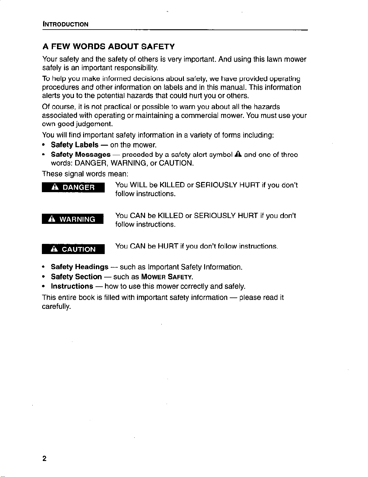
You will find important safety information in a variety of forms including:
l
Safety Labels -
l
Safety Messages
words: DANGER, WARNING, or CAUTION.
These signal words mean:
on the mower.
- preceded by a safety alert symbol a and one of three
You WILL be KILLED or SERIOUSLY HURT if you don’t
follow instructions.
You CAN be KILLED or SERIOUSLY HURT if you don’t
follow instructions.
You CAN be HURT if you don’t follow instructions.
l
Safety Headings
l
Safety Section
l
Instructions
-
such as Important Safety Information.
-
such as
MOWER SAFETY.
- how to use this mower correctly.and safely.
This entire book is filled with important safety information - please read it
carefully.
Page 5
Contents
INTRODUCTION
A Few Words About Safety.
CONTENTS.
MOWER SAFETY.
Safety Information
Important Message to Employers.
Safety Label Locations.
.................
............
.............
......
.........
CONTROLS & INDICATORS
Locations. .........
Controls. ..........
Indicators. .........
TRANSPORTING AND
Transporting your Mower
Storage Preparation.
Storage precautions.
Removal From Storage
BEFORE MOWING
Check the Mower
Check the Lawn
Prepare Yourself.
..............
.........
.........
.........
STORING
........
...........
...........
.........
............
.............
.............
.........................
.........................
.........................
.........................
.........................
..
.........................
....
.........................
.........................
........................
........................
........................
........................
........................
........................
........................
........................
........................
. . . . . . . . . . . . . . . .
........................
; . . . . . . .
2
3
5
5
6
7
9
9
10
11
13
13
13
16
16
17
17
18
18
OPERATING THE MOWER
Starting the Engine
Using the Direction Controls
Starting to Mow.
Adjusting your Speed.
Mowing Tips.
Parking the Mower
................
............
..............
..........
............
.....
......
MAINTENANCE & ADJUSTMENTS
The Importance Of Maintenance
Maintenance Safety.
Emission Control System Information
Maintenance Schedule.
Air Cleaner
Fuel ..............................................
EngineOil..
.........................................
........................................
...................................
.................................
...........................
........................
........................
........................
........................
........................
........................
........................
.......................
........................
19
19
19
21
21
22
22
23
23
23
24
26
27
28
29
3
Page 6
INTRODUCTION
Sparkplug..
Valve Clearance.
Carburetor.
Throttle Cable
Lubrication Points.
Control Linkage Adjustment
Brake Lining Thickness
Tires...............................................3 6
Cutting Height
Blades.............................................3 8
Deck Belt Adjustment And Replacement.
Blade Brake Adjustment
Blade Belt Adjustment And Replacement
Drive Belt Replacement.
......................................
.....................................
.........................................
.......................................
....................................
..............................
.................................
.......................................
..................... .40
................................
..................... .42
................................
..3 2
.33
.34
.34
.35
.35
.36
.37
.41
.43
TROUBLESHOOTING . . . , . . . . . . . . . . . . . . . . . . . . . . . . . . . . . .45
Engine.............................................4 5
Mower.............................................4 5
SPECIFICATIONS
Mower.............................................4 7
Engine.............................................4 7
.................................... .47
ADDITIONAL INFORMATION
Manual en
Honda Publications.
Customer Service Information.
Oxygenated Fuels
Modification for High Altitude Operation
Spark Arrester Service (Optional Equipment)
Espaiiol
....................................
...................................
....................................
...........................
............................
.48
.48
.48
.48
.49
...................... .49
..................
.50
4
Page 7

SAFETY INFORMATION
Most accidents with walk-behind mowers can be prevented if you follow all
instructions in this manual and on the mower. The most common hazards,
according to accident statistics, are discussed below, along with the best way to
protect yourself and others.
Avoid Rotating Blades
A rotating blade can cause serious cuts and even amputate fingers, hands, toes,
or feet. Keep away from the mower deck whenever the engine is running. If you
need to work around the deck to clear a grass accumulation, adjust the cutting
height, or for any other reason, always shut off the engine and remove the key.
Wear heavy gloves when you need to clean the mower deck or handle a blade.
Clear the Mowing Area
Mower blades can throw rocks and other objects with enough force to cause
serious injury. Before mowing, carefully inspect the area and remove all sticks,
stones, pieces of wire, and other loose objects. Never operate the blades over
gravel.
Keep Shields in Place
Guards and shields are designed to protect you from being hit by thrown objects
and from touching hot engine parts and moving components. For your safety and
the safety of others, keep all shields in place when the engine is running.
Refuel with Care
Gasoline is extremely flammable and gasoline vapor can explode. Refuel only
outdoors in a well-ventilated area with the engine OFF. Never smoke near
gasoline, and keep other flames and sparks away. Always store gasoline in an
approved container.
Wear Protective Clothing
Wearing protective clothing will reduce your risk of injury. Long pants and eye
protection reduce the risk of injuries from thrown objects. Sturdy shoes with
aggressive soles will help protect your feet and give you better traction on slopes
or uneven ground. Ear protection and a helmet may be required by local
ordinances or insurance policies.
Turn Engine Off When Not Mowing
If you need to leave the mower for any reason, even just to inspect the lawn
ahead, always turn the engine off. And take the key if you go farther away.
Page 8

MOWER SAFETY
IMPORTANT MESSAGE TO EMPLOYERS
As an employer, you have special responsibilities to the people who work for you.
Before you ask anyone to operate this mower, you need to determine whether the
person is old enough, large enough, and strong enough to safely handle and
control the mower.
Then be sure the employee reads and understands all instructions and warnings
in this manual and on the labels before operating the mower.
Allow adequate time for hands-on training by a qualified instructor, and personally
supervise practice sessions until you feel sure the employee is ready to operate
the machine.
Also be sure employees wear proper clothing and have eye protection and any
other gear that may be required by local ordinances or your insurance company.
Remember, too, that you are responsible for keeping the mower properly
maintained and in safe operating condition.
Your commitment to safety on the job can help prevent accidents and result in
longer and more productive years of service.
,
6
Page 9
MOWER SAFETY
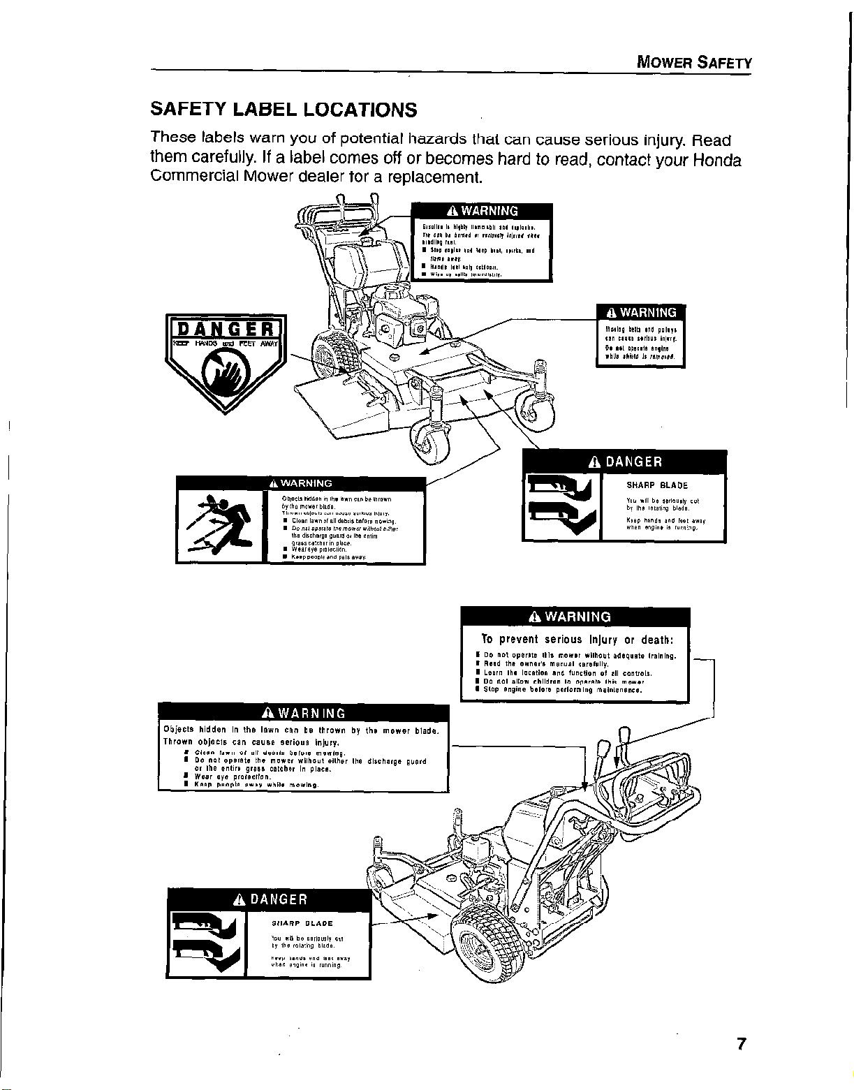
SAFETY LABEL LOCATIONS
These labels warn you of potential hazards that can cause serious injury. Read
them carefully. If a label comes off or becomes hard to read, contact vour Honda
Commercial Mower dealer for a replacement.
7
Page 10

MOWER SAFETY
8
Page 11
Controls & Indicators
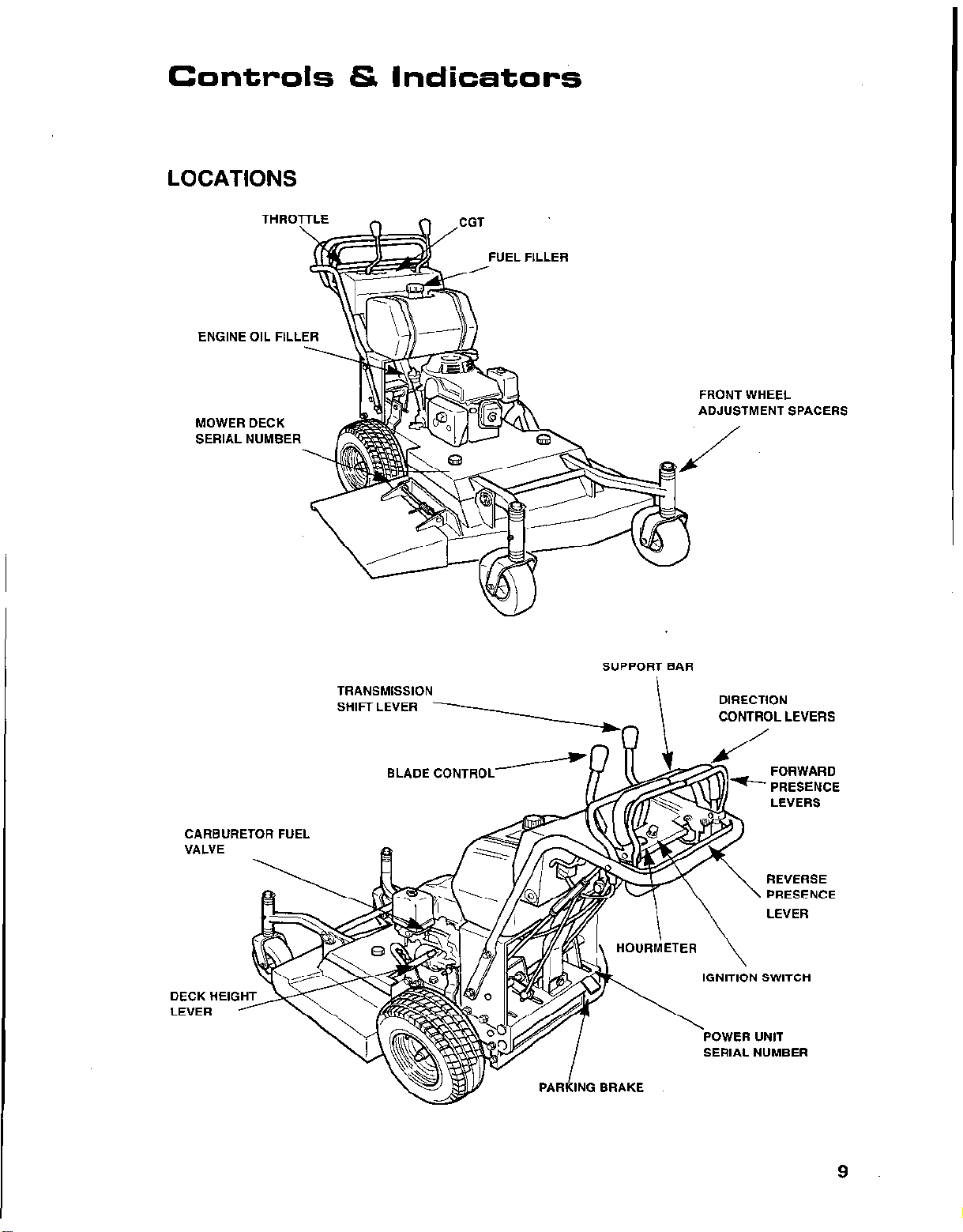
LOCATIONS
FUEL FILLER
ENGINE OIL FILL
MOWER DECK
SERIAL NUMBER
FRONT WHEEL
ADJUSTMENT SPACERS
CARBURETOR FUEL
VALVE
DECK HEI
LEVER
TRANSMISSION
SHIFT LEVER
BLADE CONTROL-
SUPPORT BAR
Y
DIRECTION
CONTROL LEVERS
FORWARD
PRESENCE
LEVERS
REVERSE
\
PRESENCE
LEVER
9
Page 12
CONTROLS & INDICATORS
CONTROLS
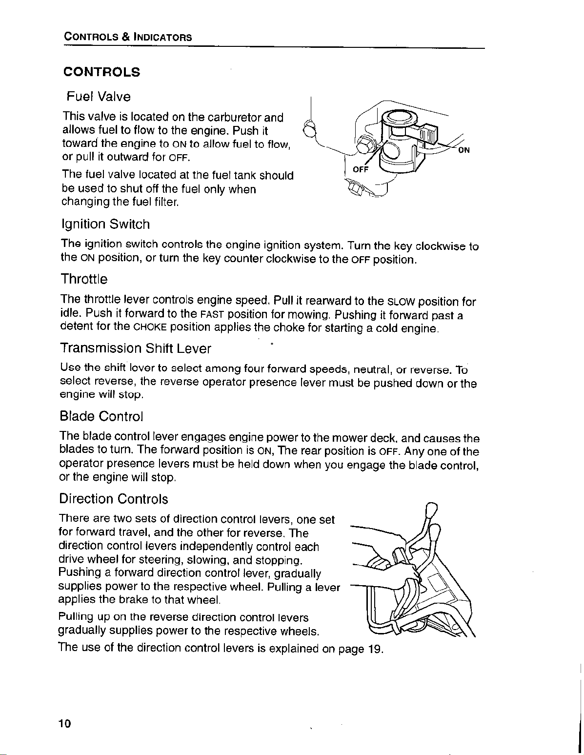
Fuel Valve
This valve is located on the carburetor and
allows fuel to flow to the engine. Push it
toward the engine to
or pull it outward for
The fuel valve located at the fuel tank should
be used to shut off the fuel only when
changing the fuel filter.
ON
to allow fuel to flow,
OFF.
ignition Switch
The ignition switch controls the engine ignition system. Turn the key clockwise to
the
ON
position, or turn the key counter clockwise to the
OFF
position.
Throttle
The throttle lever controls engine speed. Pull it rearward to the
idle. Push it forward to the
detent for the
CHOKE
position applies the choke for starting a cold engine.
FAST
position for mowing. Pushing it forward past a
SLOW
position for
0
Transmission Shift Lever
Use the shift’lever to select among four forward speeds, neutral, or reverse. To
select reverse, the reverse operator presence lever must be pushed down or the
engine will stop.
Blade Control
The blade control lever engages engine power to the mower deck, and causes the
blades to turn. The forward position is
operator presence levers must be held down when you engage the blade control,
or the engine will stop.
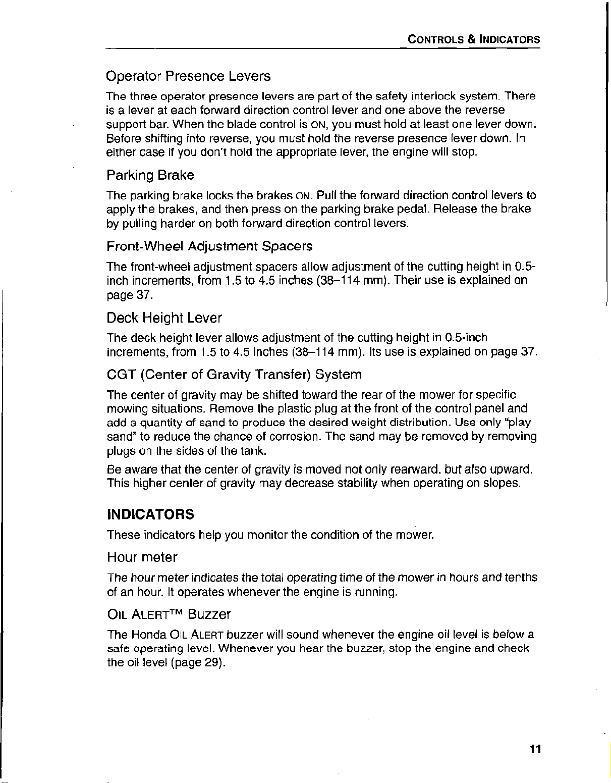
Direction Controls
There are two sets of direction control levers, one set
for forward travel, and the other for reverse. The
direction control levers independently control each
drive wheel for steering, slowing, and stopping.
Pushing a forward direction control lever, gradually
supplies power to the respective wheel. Pulling a lever
applies the brake to that wheel.
ON,
The rear position is
OFF.
Any one of the
n
Pulling up on the reverse direction control levers
gradually supplies power to the respective wheels.
The use of the direction control levers is explained on page 19.
10
Page 13
CONTROLS & INDICATORS
Operator Presence Levers
The three operator presence levers are part of the safety interlock system. There
is a lever at each forward direction control lever and one above the reverse
support bar. When the blade control is
Before shifting into reverse, you must hold the reverse presence lever down. In
either case if you don’t hold the appropriate lever, the engine will stop.
ON,
you must hold at least one lever down.
Parking Brake
The parking brake locks the brakes
apply the brakes, and then press on the parking brake pedal. Release the brake
by pulling harder on both forward direction control levers.
ON.
Pull the forward direction control levers to
Front-Wheel Adjustment Spacers
The front-wheel adjustment spacers allow adjustment of the cutting height in 0.5
inch increments, from 1.5 to 4.5 inches (38-114 mm). Their use is explained on
page 37.
Deck Height Lever
The deck height lever allows adjustment of the cutting height in 0.5inch
increments, from 1.5 to 4.5 inches (38-114 mm). Its use is explained on page 37.
CGT (Center of Gravity Transfer) System
The center of gravity may be shifted toward the rear of the mower for specific
mowing situations. Remove the plastic plug at the front of the control panel and
add a quantity of sand to produce the desired weight distribution. Use only “play
sand” to reduce the chance of corrosion. The sand may be removed by removing
plugs on the sides of the tank.
Be aware that the center of gravity is moved not only rearward, but also upward.
This higher center of gravity may decrease stability when operating on slopes.
INDICATORS
These indicators help you monitor the condition of the mower.
Hour meter
The hour meter indicates the total operating time of the mower in hours and tenths
of an hour. It operates whenever the engine is running.
OIL ALERTLY
The Honda
safe operating level. Whenever you hear the buzzer, stop the engine and check
the oil level (page 29).
Buzzer
OIL
ALERT buzzer will sound whenever the engine oil level is below a
11
Page 14

CONTROLS & INDICATORS
12
Page 15
Transporting and Storing
TRANSPORTING YOUR MOWER
Use a loading ramp to get the mower on and off the vehicle. Be sure both the
ramps and vehicle are able to support the weight of the mower and operator.
When the mower is in position, turn the fuel valve
fuel leaking.
Tie the mower down, front and rear, with ropes or straps. You may use the front
caster brackets and holes in the rear of the engine bed to tie the mower down. Be
careful not to damage linkages when tightening the ropes or straps.
Remember that the engine and exhaust system become hot during operation.
Avoid touching them.
OFF
to prevent the possibility of
STORAGE PREPARATION
Proper storage preparation is essential for keeping your mower trouble free and
looking good. The following steps will help to keep rust and corrosion from
impairing your mower’s function and appearance, and will make the engine easier
to start when you use the mower again.
Cleaning the Engine
Wash the engine by hand, and be careful to prevent water from entering the air
cleaner.
Using a garden hose or pressure washing equipment can force water into the air
cleaner. Water in the air cleaner will soak the filters and can enter the carburetor
or engine cylinder, causing damage.
Water contacting a hot engine can cause damage. If the engine has been running,
allow it to cool for at least half an hour before washing.
Cleaning the Mower Deck
If using a garden hose or pressure washing equipment to clean the mower deck,
be careful to avoid getting water into controls and cables, or anywhere near the
engine air cleaner or muffler opening.
1 NOTICE 1
Spraying water on hot mower deck bearings can cause them to be damaged from
cooling too quickly.
Before washing the underside of the mower deck, be sure the parking brake is set
and the height adjustment lever is all the way up.
Remove the grass bag (optional kit) from its frame, and wash it with a garden
hose or pressure washing equipment. Allow the bag to completely dry before
storage.
13
Page 16
TRANSPORTING AND STORING
After washing the mower, wipe dry all accessible surfaces.
Start the engine outdoors, and let it run until it reaches normal operating
temperature to evaporate any water remaining on the engine.
While the engine is running, hold an operator presence lever and operate the
blade control lever to expel water from the blade pulleys, spindles, and other
mower deck areas. Allow the blades to spin for several minutes to ensure that no
water remains.
Stop the engine and allow it to cool.
After the mower is clean and dry, touch up any damaged paint and coat other
areas with a light film or oil. Do not apply oil to the pulleys, brake drums, or to the
blade brake drum. Lubricate the throttle cable core with a silicone spray lubricant.
Fuel
Gasoline will oxidize and deteriorate in storage. Old gasoline will cause hard
starting, and it leaves gum deposits that clog the fuel system. If the gasoline in
your mower deteriorates during storage, you may need to have the carburetor and
other fuel system components serviced or replaced.
The length of time that gasoline can be left in your fuel tank and carburetor without
causing functional problems will vary with such factors as gasoline blend, your
storage temperatures, and whether the fuel tank is partially or completely filled.
The air in a partially filled fuel tank promotes fuel deterioration. Very warm storage
temperatures accelerate fuel deterioration. Fuel deterioration problems may occur
within a few months, or even less if the gasoline was not fresh when. you filled the
fuel tank.
Fuel system damage or engine performance problems resulting from neglected
storage preparation are not covered under warranty.
You can extend fuel storage life by adding a gasoline stabilizer that is formulated
for that purpose, or you can avoid fuel deterioration problems by draining the fuel
tank and carburetor.
Adding a Gasoline Stabilizer to Extend Fuel Storage Life
When adding a gasoline stabilizer, fill the fuel tank with fresh gasoline. If only
partially filled, air in the tank will promote fuel deterioration during storage. If you
keep a container of gasoline for refueling, be sure that it contains only fresh
gasoline.
1. Add gasoline stabilizer following manufacturer’s instructions.
2. After adding a gasoline stabilizer, run the engine outdoors for 10 minutes to be
sure that treated gasoline has replaced the untreated gasoline in the
carburetor.
3. Stop the engine, and turn the fuel valve to the
14
OFF
position.
Page 17
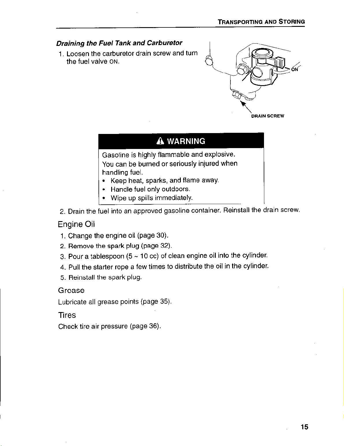
Draining the Fuel Tank and Carburetor
1. Loosen the carburetor drain screw and turn
the fuel valve
ON.
Gasoline is highly flammable and explosive.
You can be burned or seriously injured when
handling fuel.
l
Keep heat, sparks, and flame away.
l
Handle fuel only outdoors.
l
Wipe up spills immediately.
TRANSPORTING AND STORING
\
DRAIN SCREW
2. Drain the fuel into an approved gasoline container. Reinstall the drain screw.
Engine Oil
1. Change the engine oil (page 30).
2. Remove the spark plug (page 32).
3. Pour a tablespoon (5 -
10 cc) of clean engine oil into the cylinder.
4. Pull the starter rope a few times to distribute the oil in the cylinder.
5. Reinstall the spark plug.
Grease
Lubricate all grease points (page 35).
Tires
Check tire air pressure (page 36).
15
Page 18

TRANSPORTING AND STORING
STORAGE PRECAUTIONS
If your mower will be stored with gasoline in the fuel tank and carburetor, it is
important to reduce the hazard of gasoline vapor ignition. Select a well-ventilated
storage area away from any appliance that operates with a flame, such as a
furnace, water heater, or clothes dryer. Also avoid any area with a spark-
producing electric motor, or where power tools are operated.
If possible, avoid storage areas with high humidity, because that promotes rust
and corrosion.
Unless all fuel has been drained from the fuel tank, leave the fuel valve in the
position to reduce the possibility of fuel leakage.
Park the mower on a level surface. Tilting can cause fuel or oil leakage.
With the engine and exhaust system cool, cover the mower to keep out dust. A
hot engine and exhaust system can ignite or melt some materials. Do not use
sheet plastic as a dust cover. A nonporous cover will trap moisture around the
mower, promoting rust and corrosion.
OFF
REMOVAL FROM STORAGE
Check your mower as described in the Before Mowing chapter of this manual
(we 17).
If the fuel was drained during storage preparation, fill the tank with fresh gasoline.
If you keep a container of gasoline for refueling, be sure that it contains only fresh
gasoline. Gasoline oxidizes and deteriorates over time, causing hard starting.
If the cylinder was coated with oil during storage preparation, the engine may
smoke briefly at startup. This is normal.
16
Page 19

Before Mowing
CHECK THE MOWER
For your safety and the service life of your equipment, always inspect your mower
before using it. Before beginning your pre-operation check, be sure:
l
The mower is parked on a level surface.
l
The blade control lever is disengaged and the transmission shift lever is in
NEUTRAL.
l
The ignition switch is off and the key is removed.
Walk around the mower and check its general condition. Look around and
underneath it for signs of fluid leaks. Remove any excessive dirt and debris,
especially around moving components. Look for signs of damage. Check nuts,
bolts, screws, and pins for tightness.
Never operate the mower with the safety interlock system inoperative. Do not
attempt to bypass or defeat the system.
Keep all shields and covers in place while operating the mower. If you find any
problems or defects, have them repaired before mowing.
Blades
Before each use, check each mower blade for damage or abnormal wear. See
page 38 for details.
Belts
Check the blade, deck, and transmission belts for wear and correct tension. See
page 40 for details.
Engine Oil
Check the level on the dipstick. Running the engine with a low oil level will cause
engine damage. See page 29 for details.
Fuel
Remove the cap on the tank and check the fuel level. See page 28 for refueling
details.
Air Filter
Check that the air cleaner elements are clean and in good condition. See page 27
for information on servicing the air cleaner.
Cutting Height
The cutting height of your mower should be set for the mowing conditions and
should be in the same position, front and rear. See page 37 to adjust cutting
height.
17
Page 20

BEFORE MOWING
Tire Pressure
Check the tires for proper inflation (page 36 ).
CHECK THE LAWN
For your safety and the safety of others, always inspect the area before mowing.
Objects
Anything which can be picked up by the blades and thrown is a potential hazard to
you and others. Look for things like stones, sticks, bones, and wire, and remove
them from the mowing area.
People
People and animals near the mowing area can move into your mowing path or
into a position where they could be struck by thrown objects. Clear the area of
people, especially children and pets. Their safety is your responsibility.
Lawn
Check the length and condition of the grass. Adjust your mowing speed and
cutting height accordingly.
Avoid mowing wet grass. Not only does mowing wet grass result in poor cut
quality, it also provides poor traction, increasing your risk of losing your footing.
PREPARE YOURSELF
Your safety is your responsibility. A little time spent in preparation will significantly
reduce your risk.
Knowledge
Read and understand this manual. Know what the controls do and how to operate
them.
Familiarize yourself with the mower and its operation before you begin mowing.
Know what to do in case of emergencies.
Clothing
Wearing protective clothing will reduce your risk of injury.
Long pants and eye protection reduce the risk of injuries from thrown objects.
Sturdy shoes with aggressive soles will help protect your feet and give you better
traction on slopes or uneven ground.
While the sound level of the mower is well within safe limits, hearing protection will
further protect your hearing.
18
Page 21

Operating the Mower
The Honda Mid-Size Commercial Mower is a powerful, highly maneuverable
mower designed to enhance the productivity of a lawn-care professional. You will
need a complete understanding of its operation and a certain amount of practice
with its controls to safely realize the full potential of this mower.
Read this section completely before operating the mower. Take time to familianze
yourself with the controls and how they operate. Get used to the feel of the
transmission shift lever and direction control levers by running the engine at about
half-throttle.
The small amount of time spent in familiarization will reward you with greater
efficiency and reduced risk.
STARTING THE ENGINE
Because of the risk of carbon monoxide poisoning, it makes good sense to start
the mower outside; or at least in an open area with good ventilation.
1. Pull the blade control lever to
OFF.
(The mower should not be started without
the entire grass catcher or the discharge guard in place.)
2. Place the transmission shift lever in
NEUTRAL.
3. The safety interlock system will prevent the engine from starting if the blade
control is
ON
or if the transmission is in
REVERSE.
(Do not attempt to disconnect
or modify the safety interlock system.)
4. Open the fuel valve. Check the fuel valve at the tank to be sure it is open.
5. Turn the key
l
To start a cold engine, move the throttle lever to the
l
To restart a warm engine, move the throttle lever to the
6. When the engine warms up, move the throttle lever back to the
for mowing, or the
the throttle lever out of
ON.
SLOW
CHOKE
CHOKE
position.
FAST
position.
FAST
position
position to idle. For best engine performance, move
position as soon as the engine will run smoothly.
USING THE DIRECTION CONTROLS
The direction control levers allow you to control the speed and direction of the
mower.
The mower will quickly respond to the position of the levers. To avoid abrupt
changes of direction, squeeze the levers toward the support bar rather than
treating them like a switch. Operate the mower with the transmission in first gear
until you are familiar with the sensitivity of the direction control levers.
19
Page 22

OPERATING THE MOWER
Moving Forward
Rest your finger tips on the support bar while
you squeeze the direction control levers
forward. As the levers move forward, they
apply tension to the drive belts and power to
the wheels. When the levers are fully forward,
the belts are fully engaged. The maximum
speed of the mower is controlled by the gear
you select with the transmission shift lever.
Steering the Mower
To steer the mower to the right, gradually
release pressure on the right-hand direction
control lever.
To steer the mower to the left, gradually
release pressure on the left-hand direction
control lever.
As you release pressure on a direction control
lever, that respective wheel will turn slower
and the mower will turn
Tighter turns can be made by pulling rearward
on a direction control lever to apply the brake
on that wheel
in that direction
Stopping the Mower
Pull the direction control levers rearward to apply brakes
Reversing the Mower
With the mower stopped, press on the
reverse presence lever, then shift the
transmission lever into reverse. If you do
not hold the presence lever, the engine
will shut off.
Squeeze the reverse direction control
levers. To steer to your right, gradually
release pressure on the right
direction control lever. Steer to the left by
releasing pressure on the left lever.
reverse
20
Page 23

OPERATING THE MOWER
Making an Emergency Stop
Grab the forward direction control levers and pull.
STARTING TO MOW
Objects hidden in the lawn can be thrown by the
mower blades.
Thrown objects can cause serious injury.
. Clear lawn of all debris before mowing.
l
Do not operate the mower without either the discharge chute, mulching plug, or the entire grass
catcher in place.
I
l
Wear eye protection.
~ Keep people and pets away.
For best cutting performance, always mow with the throttle lever in
To begin mowing:
1
FAST
position.
1. Select your desired ground speed with the transmission shift lever
2. Depress the operator presence lever on one of the forward direction control
levers.
3. Slowly move the blade control lever to
ON
to start the blades rotating.
4. Rest your finger tips on the support bar and squeeze the direction control
levers forward.
ADJUSTING YOUR SPEED
Your mowing speed should be controlled by the transmission gear you have
selected -the direction control levers should be in their full forward position for
normal mowing. If you find that mowing conditions cause you to operate with the
forward direction control levers pulled slightly back, shift to a lower gear. You may
shift gears while the mower is in motion.
picq
Operating the mower for a long period of time with the direction control levers
partially engaged will cause damage to the belts.
21
Page 24

OPERATING THE MOWER
MOWING TIPS
Your mower is designed to trim closely on the left hand side and discharge
clippings evenly on the right hand side.
For best cut quality, run the engine with the throttle lever in
Always mow in daylight, or under good artificial light.
FAST.
Mowing on Slopes
Mow across slopes, not up and down. Avoid steep slopes (more than 20”) and be
careful when changing direction.
When changing direction, always turn the mower up-slope. This will give you
better control and help you maintain your balance.
Avoid abrupt changes of direction or speed when operating on slopes.
Avoid stopping on a slope. If you must stop on a slope, apply the parking brake if
you leave the machine unattended. To start on a slope, keep the throttle at
to help you avoid abrupt changes of direction.
Mowing on a slope when the grass is damp or wet could cause you to slip, fall, or
lose control of the mower.
SLOW
PARKING THE MOWER
To stop the mower:
1. Pull both forward direction control levers to the rear to apply the brakes.
2. Press the parking brake pedal to lock the brakes on.
3. Pull the blade control to
4. Move the throttle to
5. Turn the key off and remove it.
6. Turn the carburetor fuel valve
Try to park the mower on level ground. If you must park it on a slope, apply the
parking brake securly to prevent the mower from rolling. Always remove the key
when leaving the mower unattended to prevent children or unauthorized persons
from operating it.
OFF.
SLOW
and let the engine idle.
OFF.
22
Page 25

Maintenance & Adjustments
THE IMPORTANCE OF MAINTENANCE
Good maintenance is essential for safe, economical, and trouble-free operation. It
will also help reduce air pollution..
Incorrect maintenance, or failure to correct a
problem before operation, can cause a malfunction
in which you can be seriously hurt or killed.
Always follow the inspection and maintenance
recommendations and schedules in this owner’s
manual.
To help you properly care for your mower, the following pages include a
maintenance schedule, routine inspection procedures, and simple maintenance
procedures using basic hand tools. Other service tasks that are more difficult, or
require special tools, are best handled by professionals and are normally
performed by a Honda technician or other qualified mechanic.The maintenance
schedule applies to normal operating conditions. If you operate your mower under
severe conditions, such as sustained high-load or high-temperature operation, or
use in unusually wet or dusty conditions, consult your servicing dealer for
recommendations applicable to your individual needs and use.
Maintenance, replacement, or repair of the emission control devices and
systems may be performed by any engine repair establishment or
individual, using parts that are “certified” to EPA standards.
MAINTENANCE SAFETY
Some of the most important safety precautions follow. However, we cannot warn
you of every conceivable hazard that can arise in performing maintenance. Only
you can decide whether or not you should perform a given task.
Failure to properly follow maintenance instructions
and precautions can cause you to be seriously hurt
or killed.
Always follow the procedures and precautions in the
owner’s manual.
23
Page 26

MAINTENANCE & ADJUSTMENTS
Safety Precautions
l
Make sure the engine is off before you begin any maintenance or repairs. This
will eliminate several potential hazards:
- Carbon monoxide poisoning from engine exhaust.
adequate ventilation whenever you operate the engine.
- Burns from hot parts.
touching.
- Injury from moving parts.
l
Read the instructions before you begin, and make sure you have the tools and
skills required.
l
To reduce the possibility of fire or explosion, be careful when working around
gasoline. Use only a nonflammable solvent, not gasoline, to clean parts. Keep
cigarettes, sparks, and flames away from all fuel-related parts.
l
For certain operations, the mower must be raised off the ground. Be sure the
mower is solidly supported before you put any part of your body under it.
l
Wear heavy gloves when near the mower deck, belts, or blades.
Remember that your authorized Honda servicing dealer knows your mower best
and is fully equipped to maintain and repair it.
Let the engine and exhaust system cool before
Do not run the engine unless instructed to do so.
Be sure there is
To ensure the best quality and reliability, use only new, genuine Honda parts or
their equivalents for repair and replacement.
EMISSION CONTROL SYSTEM INFORMATION
Source of Emissions
The combustion process produces carbon monoxide, oxides of nitrogen, and
hydrocarbons. Control of hydrocarbons and oxides of nitrogen is very important
because, under certain conditions, they react to form photochemical smog when
subjected to sunlight. Carbon monoxide does not react in the same way, but it is
toxic.
Honda utilizes lean carburetor settings and other systems to reduce the emissions
of carbon monoxide, oxides of nitrogen, and hydrocarbons.
The U.S and California Clean Air Acts
EPA and California regulations require all manufacturers to furnish written
instructions describing the operation and maintenance of emission control
systems.
The following instructions and procedures must be followed in order to keep the
emissions from your Honda engine within the emission standards.
24
Page 27

MAINTENANCE & ADJUSTMENTS
Tampering and Altering
Tampering with or altering the emission control system may increase emissions
beyond the legal limit. Among those acts that constitute tampering are:
l
Removal or alteration of any part of the intake, fuel, or exhaust systems.
l
Altering or defeating the governor linkage or speed-adjusting mechanism to
cause the engine to operate outside its design parameters.
Problems that may Affect Emissions
If you are aware of any of the following symptoms, have your engine inspected
and repaired by your servicing dealer.
l
Hard starting or stalling after starting.
l
Rough idle.
l
Misfiring or backfiring under load.
l
Afterburning (backfiring).
l
Black exhaust smoke or high fuel consumption.
Replacement Parts
The emission control systems on your new Honda engine were designed, built,
and certified to conform with EPA and California emission regulations. We
recommend the use of genuine Honda parts whenever you have maintenance
done. These original-design replacement parts are manufactured to the same
standards as the original parts, so you can be confident of their performance. The
use of replacement parts that are not of the original design and quality may impair
the effectiveness of your emission control system.
A manufacturer of an aftermarket part assumes the responsibility that the part will
not adversely affect emission performance. The manufacturer or rebuilder of the
part must certify that use of the part will not result in a failure of the engine to
comply with emission regulations.
Maintenance
Follow the maintenance schedule on the following page. Remember that this
schedule is based on the assumption that your machine will be used for its
designed purpose. Sustained high-load or high-temperature operation, or use in
unusually wet or dusty conditions, will require more frequent service.
25
Page 28

MAINTENANCE & ADJUSTMENTS
MAINTENANCE SCHEDULE
‘Service more frequently when used in dusty areas
2Replace paper filter element only
*First oil change only
26
Page 29

MAINTENANCE & ADJUSTMENTS
AIR CLEANER
Check that the air cleaner elements are clean and in
good condition. A dirty air cleaner will restrict air flow to
the engine, reducing performance. A damaged air
cleaner will allow dirt to enter the engine, causing rapid
engine wear.
1.
Remove the wing nut to remove the air cleaner cover.
If the foam element appears clean over more than
half its surface, it does not need cleaning. Reinstall
the cover. If the foam element appears dirty, go to
Step 2.
2.
Remove the elements. Do not allow dirt to fall into the
carburetor.
3.
Separate the foam element from the paper element
and carefully check each one for holes or tears.
Replace any damaged element.
4.
Clean the foam element by squeezing it in warm
soapy water, rinsing it, and allowing it to dry. You may
also use a nonflammable solvent and then allow it to dry.
Gasoline is highly flammable and explosive.
You can be burned or seriously injured.
Never use gasoline to clean engine parts. Use a
nonflammable solvent.
5.
Oil the foam element by dipping it in clean engine oil and squeezing out all
excess oil. If too much oil is left in the foam, the engine will smoke when you
first start it.
6.
Clean the paper element by tapping it on a hard surface to knock off dirt or by
blowing compressed air (at less than 207 kPa (30 psi}) through the filter from
the inside. Never try to brush off the dirt -that will just force it into the filter
fibers.
7.
Remove any dirt from the inside of the air cleaner housing and cover. Be
careful not to allow dirt into the duct leading to the carburetor.
a.
Place the foam element over the paper element and install them. Install the
cover with its wing nut.
Operating the engine with no air cleaner or with damaged elements can cause
rapid engine wear.
27
Page 30

MAINTENANCE & ADJUSTMENTS
FUEL
Fuel tank capacity: 24.6 liters, 6.5 gallons
.
Refueling
Remove the cap on the tank and check the fuel level. Refuel carefully to avoid
overfilling or spilling fuel. There should be no fuel in the filler neck.
Gasoline is highly flammable and explosive.
You can be burned or seriously injured.
When refueling:
l
Stop engine and keep heat, sparks, and flame
away.
l
Refuel only outdoors.
l
Wipe up spills immediately.
Never refuel the mower inside a building where fumes may reach an open flame
or spark. Keep gasoline away from appliance pilot lights, electric motors, etc.
Refuel in a well-ventilated area before starting the engine. If the engine has been
running, allow it to cool. Avoid overfilling the tank or spilling fuel.
Spilled fuel not only creates a fire hazard, it can cause environmental damage.
Wipe up spills immediately. Dispose of gasoline properly.
Fuel Recommendation
Use unleaded gasoline with a pump octane rating of 66 or higher.
This engine is certified to operate on unleaded gasoline. Unleaded gasoline
produces fewer engine and spark plug deposits and extends exhaust system life.
Never use stale or contaminated gasoline or oil/gasoline mixtures. Avoid getting
dirt or water in the fuel tank.
Occasionally, you may hear light “spark knock” or “pinging” (a metallic rapping
noise) when operating under heavy loads. This is no cause for concern.
If spark knock or pinging occurs at a steady engine speed, under normal load, the
engine can be damaged. Try using fresh gasoline in the tank or change brands of
gasoline. If spark knock or pinging persists, contact your authorized Honda
Commercial Mower dealer.
Running the engine with persistent spark knock or pinging can cause engine
damage. This type of damage is not covered by the Distributor’s Limited Warranty.
28
Page 31

Changing the Fuel Filter
Change the fuel filter at the recommended interval.
1. Close the fuel shut-off valve at the fuel
tank.
2. Place a container under the filter to
catch any spilled fuel.
3. Squeeze the hose clamps and remove
the lines from the filter.
4. Install the new filter with the arrow
pointing toward the engine.
5. Be sure the clamps securely hold the
fuel lines to the new filter.
6. Dispose of the old filter and any spilled
fuel properly and open the fuel shut-off
valve at the fuel tank.
7. Check for leaks.
MAINTENANCE 8t ADJUSTMENTS
ENGINE OIL
Engine Oil Capacity: 1 .l liters, 1.2 US quarts
Checking the Level
1. Clean the area around the oil filler cap,
remove it, and wipe the dipstick with a clean
cloth.
2. Insert the dipstick without screwing it into the
filler neck. Remove the dipstick and check the
oil level on it.
3. If the oil level is low (near the bottom of the
dipstick), add enough oil to bring the level to
the upper mark on the dipstick. Do not overfill.
piq
Running the engine with a low oil level will cause
engine damage.
UPPER LIMIT
OWER LIMIT
29
Page 32

MAINTENANCE & ADJUSTMENTS
Recommended Oil
Use a high-detergent, premium quality 4-stroke engine oil certified to meet API
Service Classification SJ or equivalent.
- 20
- 20
0
20
10
AMBIENT TEMPERATURE
40
0
60
10 20 30 40°C
80
100°F
SAE 1 OW-30 is recommended for general, all-temperature use. Other viscosities
shown in the chart may be used when the average temperature in your area is
within the indicated range.
Changing the Engine Oil
Change the oil at the recommended interval or more
frequently under extreme operating conditions.
Drain the oil while the engine is warm to assure rapid
and complete draining.
1. Install one end of a section of M”-hose over the
drain outlet and place the other end in a suitable
container to catch the used oil.
2. Clean the area around the oil filler cap and remove it.
3. Turn the drain valve counterclockwise about 4 turns to open it. Do not open the
valve more than 6 turns to avoid damaging the seals.
4. When the oil has drained, turn the valve clockwise to close it and remove the
section of hose. To avoid damaging the valve, do not over-tighten it.
5. Refill the engine with the correct amount of the recommended oil.
6. After running the engine, recheck the oil level and adjust if necessary.
pGTicq
Improper disposal of engine oil can be harmful to the environment. If you change
your own oil, please dispose of it properly. Put it in a sealed container, and take it
to a recycling center. Do not discard it in a trash bin or dump it on the ground.
30
Page 33

MAINTENANCE & ADJUSTMENTS
Changing the Engine Oil Filter
1. Drain the engine oil.
2. Remove the oil filter and let the remaining oil
drain out.
3. Correctly dispose of the old oil filter.
4. Clean the filter base with a clean cloth.
5. Coat the O-ring of the new filter with clean
engine oil.
6. Hand tighten the oil filter until the O-ring seats against the filter base.
7. Tighten the filter by hand an additional % - 1 turn.
8. Pour the specified amount of oil into the engine. Run the engine for a few
minutes and check for leaks in the area of the filter base.
9. Stop the engine and check the oil level. Adjust if necessary.
A Honda oil filter wrench will simplify the removal and installation of the filter. The
wrench, P/N 07912-6110001, is available from your authorized Honda servicing
dealer.
31
Page 34

.
MAINTENANCE & ADJUSTMENTS
SPARK PLUG
Recommended Types
NGKBPRSES
NDWlGEPR-U
(1
Spark plugs of the wrong size or incorrect heat range can cause engine damage.
Checking the Spark Plug
For good performance, the spark plug should have the correct gap and be free of
deposits.
1.
Disconnect the spark plug cap and
remove any dirt from around the spark
plug area.
2.
Remove the spark plug with a
13/,s -inch spark plug wrench.
3.
Inspect the spark plug for excessively
worn electrodes, chips or cracks in the
insulator, or excessive deposits.
Replace the spark plug if you have any
doubts about its condition.
4.
Measure the electrode gap with a wire gap gauge.
Adjust the gap to 0.7 - 0.6 mm (0.026 - 0.031 in) by
bending the side electrode.
5.
Install the plug carefully, by hand, to avoid cross
threading.
6.
Use a spark plug wrench to tighten the plug enough
to compress the washer. For a used plug, tighten ‘/a
to 1/4 of a turn after the spark plug seats. For a new
plug, tighten I/* turn after the spark plug seats.
A loose spark plug can become hot enough to damage
the engine. Over tightening a spark plug can damage the threads in the engine.
7. Install the spark plug cap on the plug.
n
0.7
-
0.8
mm
in)
32
Page 35

MAINTENANCE & ADJUSTMENTS
VALVE CLEARANCE
Adjust the valves at the recommended interval.
Valve clearance inspection and adjustment must be done with the engine cold.
1. Remove the valve cover.
2. Set the piston at top dead center of the
compression stroke (both valves will be
fully closed). The cutout mark in the
starter pulley will align with the index
mark on the fan cover when the piston
is at top dead center of either the
compression or exhaust stroke.
.
3. Measure the clearance between the rocker
arm and the valve with a feeler gauge.
INTAKE 0.08 - 0.12 mm
EXHAUST 0.13 - 0.17 mm
4.
To adjust valve clearance, hold the rocker arm
pivot and loosen the pivot lock nut.
Turn the rocker arm pivot to obtain the
5.
specified clearance.
Hold the rocker arm pivot and tighten
6.
the pivot lock nut.
Recheck the clearance and readjust if
7.
necessary.
Install the valve cover.
a.
INTAKE 0.08 - 0.12 mm
EXHAUST 0.13 - 0.17 mm
33
Page 36

MAINTENANCE & ADJUSTMENTS
CARBURETOR
Perform this adjustment if the idle is slow or rough and you’re sure the air cleaner
and spark plug are in good condition.
1. Start the engine in an area with adequate ventilation to
avoid carbon monoxide poisoning. Allow the engine to
warm to normal operating temperature.
IDLE STOP SCREW
2. With the throttle lever at
SLOW,
turn-the throttle stop
screw to set the idle speed.
IDLE SPEED 1750-1950 rpm
The pilot screw is fitted with a limiter cap to prevent
excessive enrichment of the fuel-air mixture. Do not
attempt to remove the limiter cap. It cannot be removed
without breaking the pilot screw.
THROTTLE CABLE
In normal use, cables will lose their adjustment. Perform this procedure if the noload speed is not within limits or the engine does not seem to respond correctly to
throttle lever movements, or if the choke doesn’t fully close.
II
GOVERNOR SPRING
\
CABLE HOLDER
SCREW
1. Set the throttle lever to
FAST.
2. On the engine, check the clearance between the control lever and the choke
lever. It should be 1 mm (0.04 in) or less. In other words, just touching. The
choke should be fully open.
3. If you need to adjust the clearance, loosen the cable holder and adjust the
position of the cable housing.
4. Next, set the throttle lever to
CHOKE.
5. Adjust the stopper screw so that it just contacts the choke lever when the
choke is fully closed.
6. Check maximum engine speed with a tachometer. Adjust the cable slightly to
obtain the rated speed.
MAXIMUM NO-LOAD SPEED 3550 *50 rpm
34
Page 37

MAINTENANCE & ADJUSTMENTS
LUBRICATION POINTS,
Grease: NGLI #2 Lithium Base EP
Follow the diagram to lubricate these
fittings.
l
Caster wheels (2)
l
Caster pivots (2)
l
Pulley pivots (1)
. Spindles (2 or 3) Do not over
grease the spindle. Use a long
narrow screwdriver to check for
grease between the pulley and the
deck. If you find grease there, you
have enough.
SPINDLES
CASTER WHEELS
CONTROL LINKAGE ADJUSTMENT
1. Push the right-hand forward direction
control lever as far forward as you can
with finger pressure
n There should be a gap of 70 mm (23X)
L.
between the direction control lever and
the support bar.
PULLEY PIVOT /
STER PIVOTS
To adjust the gap, loosen the two
3.
locknuts on the linkage (the top nut has
left-hand threads) and turn the collar to
set the desired gap. Hold the collar and
tighten the lock nuts.
4,
Now, pull the direction control lever
rearward with finger pressure
5. There should be a gap of 100 mm (4”)
between the direction control lever and
the support bar.
35
Page 38

MAINTENANCE & ADJUSTMENTS
6. To adjust the gap, remove the cotter pin
and washer from the brake rod swivel.
Screw the swivel in or out on the rod to
set the desired gap. (The swivel always >
goes into the forward hole.) Install the
washer and a new cotterpin.
7. Repeat the process with the left-hand
direction control lever, so that the left
lever travel matches that of the right
lever.
BRAKE LINING THICKNESS
Check the thickness of the brake lining on
both wheels as called out in the
maintenance schedule.
The total thickness of the friction material
and the band cannot be less than 3.2 mm
(‘/a”) at any point.
TIRES
.
FRONT TIRE PRESSURE: 193 KPA (28 PSI)
REAR TIRE PRESSURE: 103 KPA (15 PSI)
Incorrect tire inflation can cause the mower not to track in a straight path.
Replace the tires when the tread is worn. Worn-out tires will not provide good
traction, especially on slopes and uneven ground.
36
Page 39

MAINTENANCE & ADJUSTMENTS
CUTTING HEIGHT
The cutting height of your mower can be easily adjusted from 38 mm to 115 mm
(1% to 4% inches). Always shut off the engine and remove the key before
adjusting cutting height.
Be sure to adjust both the front and rear wheels
to the same cutting height to get the best
performance and cut quality.
Front Wheel Adjustment
The front caster wheels are adjustable in increments of 13 mm (XZJ”) by changing
the position of the six spacers on each caster post. The following table shows the
position of the spacers for the various cutting heights.
NUMBER OF LOWER SPACERS
0
1.5" 2.0" 2.5" 3.0" 3.5" 4.0" 4.5"
To change the spacers:
1 2
3
1. Raise and support the front of the mower
deck.
2. Remove the pin and lower the caster post
about 6 mm (W’) until the spacer can be
removed over the flats in the caster post.
3. Position the spacers in the desired locations.
4. Raise the caster post and insert and lock the
pin.
5. Repeat the procedure on the other caster
wheel.
Do not change the location of the washers on the
caster post.
Rear Deck Adjustment
The rear wheels are adjustable in 13 mm
(X1’) increments by moving the deck height
lever. Be sure that the setting for the deck
matches the setting for the caster wheels.
4
5
6
37
Page 40

MAINTENANCE & ADJUSTMENTS
BLADES
It is important for your safety and the safety of others that you inspect the blades
for condition and correct installation before operating the mower.
A worn, cracked, or damaged blade can break and
pieces of the broken blade can become dangerous
projectiles.
Thrown objects can cause serious injury.
Inspect the blades regularly and do not operate the
mower with a worn or damaged blade.
The blades are subject to wear during normal operation and shouldJbe inspected
regularly.
If a blade strikes an object, it may be damaged. Immediately stop the mower and
inspect the blades.
Before working on or around the blades, disconnect the spark plugs connectors
from the spark plugs. This will prevent the engine from starting inadvertently
Always wear heavy gloves to protect your hands when working with or near the
mower blades.
Inspecting the Blades
NEW WORN BENT CRACKED
1. Turn the ignition switch key
2. Move the blade control lever
OFF
and remove the key from the switch.
OFF.
3. Raise and support the front of the mower deck.
4. Inspect each of the blades for cracking, bending, deep nicking, and wear.
If any of the blades show signs of damage or excessive wear, remove the blades
for a more thorough inspection.
Removing the Blades
1. Turn the ignition switch key
OFF
and remove the key from the switch.
2. Move the blade control lever
OFF
3. Remove the belt cover(s) by removing the knobs.
4. Raise and support the front of the mower deck
38
Page 41

MAINTENANCE & ADJUSTMENTS
5. Use a block of wood to prevent the
blade from turning and remove the bolt
washer, blade, and spacer.
picq
Do not hold the nut on the top of the
spindle. Loosening the nut will affect the
spindle bearing preload.
6. Repeat the process for the other
blade(s).
Installing the Blades
1. Reinstall the blades by placing the
washer, blade, and spacer over the
bolt.
2. Insert the bolt into the spindle and tighten it by hand.
3. Hold the nut on top of the spindle with a wrench and tighten the blade bolt to
88 - 102 N.m (65 175 ft-lb) iorque.
4. Repeat the procedure for the other blade(s).
5. Lower the mower deck to the ground.
6. Install the belt cover(s) with the knobs.
Servicing the Blades
A dull blade may be sharpened, but a blade that is worn out,
bent, cracked, or otherwise damaged must be replaced.
Always use genuine Honda replacement blades. Substitute
blades may not meet Honda specifications and may be
dangerous.
To sharpen a blade:
l
Maintain the original angle of the blade (about 30”)
l
Leave a blunt edge of 1 mm (1/ls - 1/32 in). Do not sharpen
to a knife edge.
l
Remove an equal amount of material from each end of the
blade to maintain balance.
l
Do not remove material from the inner area of the cutting
edge. If you need to remove material to restore the cutting
edge, taper the edge toward the tip. Do not taper beyond
TAPER THE
CUTTING EDGE
BLUNT EDGE
1/3 of the blade width.
l
Do not grind the b?ck side of the blade.
l
Check the balance of the blade by placing a dowel through the mounting hole.
The blade should remain horizontal. If one end drops, remove additional
material from it to make it lighter and recheck the balance.
39
Page 42

MAINTENANCE & ADJUSTMENTS
DECK BELT ADJUSTMENT AND REPLACEMENT
Replace the deck belt if it is worn, frayed, or glazed. You will need to remove the
deck belt to replace the transmission belts and disconnect it to replace the blade
belt. Whenever you remove and replace the deck belt, check the adjustment of
the belt guides, belt tension, and the blade brake.
Moving belts and pulleys can cause serious injuries.
Do not operate engine with the belt cover(s)
removed.
Before removing belt cover(s) for maintenance,
remove key from ignition switch and disconnect the
spark plug lead.
Adjust Belt Tension
1. Remove the belt cover.
2. Fully lower the rear of the deck and move
the blade control
ON.
Shown from beneath mower.
TENSIONER PULLEY
3. Measure the length of the tensioner spring.
TENSIONER SPRING LENGTH: 1% in
4.
Move the blade control
OFF
to turn the
adjusting butterfly nut.
5. Check the blade brake adjustment if you
change the belt tension (page 41).
6. Install the belt cover.
40
Page 43

MAINTENANCE & ADJUSTMENTS
Replace Belt
1. Move the blade control
OFF
and remove the belt
48-inch deck shown
cover.
2. Loosen the two nuts on the belt guide at the deck
pulley.
3. Starting at the engine pulley, lift the belt out of the
pulley grooves.
4. Install the new belt by first setting it in the deck pulley,
then the tensioner pulley, and finally the engine
pulley.
.
5. Tighten the two nuts on the belt guide at the deck
pulley.
6. Adjust the belt tension and blade brake.
BLADE BRAKE ADJUSTMENT
Check the blade brake adjustments after the deck belt is adjusted or replaced.
Moving belts and pulleys can cause serious injuries.
Do not operate engine with the belt cover(s)
removed.
Before removing belt cover(s) for maintenance,
remove key from ignition switch and disconnect the
spark plug lead.
1. Fully lower the rear of the deck, move
the blade control
OFF,
and remove the
belt cover(s).
2. Remove the hairpin clip and lower
washer from the brake rod at the pivot
plate. The rod should slip freely in and
out of the hole in the arm. If not, screw
the rod in or out of the pivot at the
tensioner arm until it’s a slip fit.
3. Install the rod in the pivot plate with two
washers and two hairpin clips as shown.
4. Start the engine and engage and
release the blade control several times.
Confirm that the brake operates
correctly.
___
..__-. -
==:--.-
--__..-.--
5. Install the belt cover.
41
Page 44

MAINTENANCE & ADJUSTMENTS
BLADE BELT ADJUSTMENT AND REPLACEMENT
Replace the blade belt if it is worn, frayed, or glazed.
Moving belts and pulleys can cause serious injuries.
Do not operate engine with the belt cover(s)
removed.
Before removing belt cover(s) for maintenance,
remove key from ignition switch and disconnect the
spark plug lead.
.
Inspect and Adjust
1. Move the blade control
OFF.
Remove the belt
ANCHOR BOLT
cover(s).
2. Check the tensioner spring length.
MINIMUM SPRING LENGTH
(hook-to-hook):
120 - 140 mm (4% - 5% in)
If the spring is too short, adjust the tensioner:
3. Remove the blade belt from the right (discharge
side) pulley.
4. Remove the spring from the anchor bolt and
.
48-inch deck shown
. .
install the bolt in an alternate hole. Install the spring over the bolt.
5. Install the belt over the pulleys
If the spring is still too short with the anchor bolt in the last position, replace the
belt.
6. Install the belt cover.
Replace
0
48-inch deck
36-inch deck
1. Move the blade control
OFF
and remove the belt cover.
2. From under the deck, remove the two nuts from the deck belt guide
42
[A].
Page 45

MAINTENANCE & ADJUSTMENTS
3. From under the deck, remove the nuts from the blade brake pivot
brake rod stay [cl.
4. Remove the deck belt from the pulley.
5. Remove the blade belt from the right (discharge side) pulley
the remaining pulley(s).
6. The tensioner spring anchor bolt
7. Install the new belt over the pulleys.
8. Install the deck belt on its pulley.
9. Install the blade brake pivot and brake rod stay. Install the deck belt guide.
IO. Check the adjustment of the blade brake.
[E]
should be in the shortest position.
[D],
[B]
and the
and then from
DRIVE BELT REPLACEMENT
Replace the transmission belts if they are worn, frayed, or glazed. You will need to
remove the deck belt from the engine pulley first.
Moving belts and pulleys can cause serious injuries.
Do not operate engine with the belt cover(s)
removed.
Before removing belt cover(s) for maintenance,
remove key from ignition switch and disconnect the
spark plug lead.
Remove
1. Loosen but do not remove the four beltguide nuts on the top of the deck.
2. Remove the right-side transmission belt
first by sliding the belt off the
transmission pulley, then off the
tensioner, and the engine pulley.
3. Remove the left-side belt in a similar
manner.
Do not change the positions of the belt
guides on the tensioner pulleys. The belts
may be removed without loosening the tensioner pulley bolt.
43
Page 46

MAINTENANCE & ADJUSTMENTS
Install
Viewed from above the mower
ENGINE PULLEY
LEFT
TRANSMISSION
GUIDE
BELT GUiDE
I!-- PULLEY
TRANSMISSION
The left-side belt is longer than the right-side.
1. Slip the left-side belt over the engine pulley, then the tensioner pulley, and
finally the transmission pulley. Do not change the positions of the belt guides
on the tensioner pulleys.
2. Install the right-side belt in a similar manner.
3. Move all belt guides so that they are close to but not touching the belts when
tension is applied.
4. Install the deck belt (page 40).
5. Adjust the control linkages (page 35).
44
Page 47

Troubleshooting
ENGINE
Doesn’t Start
l
The key must be
l
Blade control must be
l
Transmission must NOT be in
l
Fuel tank should be full of fresh fuel (page 28).
l
Fuel filter should be clean and free of obstructions (page 29).
l
Both fuel valves should be on (page 10).
l
Throttle should be in
l
Spark plug connector should be firmly attached to the spark plug.
l
Spark plug should be correctly gapped and be free of deposits (page 32).
Low Power
l
Air cleaner elements should be clean (page 27).
l
Spark plug should be correctly gapped and be free of deposits (page 32).
l
Mower deck should be free of grass accumulation.
l
Tall grass should be cut at lower speeds and/or higher cutting heights.
l
Incorrect carburetor or linkage adjustment (page 34).
ON.
OFF.
CHOKE
REVERSE.
for cold engine,
FAST
for warm engine.
MOWER
Doesn’t Move
l
Forward speed controls must be out of
l
Parking brake must be released
l
The drive belts must be in good condition (page 43).
NEUTRAL.
Pulls To One Side
l
Tires should be correctly inflated (page 36).
. . The control linkages must be correctly adjusted (page 35).
l
The drive belts must be in good condition (page 43).
Vibrates
l
Blades should be in good condition (page 38).
l
The deck must be free of any accumulation of clippings.
l
Deck and blade belts should be in good condition and at correct tension
(page 40 & page 42).
45
Page 48

I
TROUBLESHOOTING
Cuts Poorly
l
Throttle should be in
l
Cutting height must be at the same setting at front and rear (page 37).
l
Blades should be in good condition (page 38).
l
Mower deck should be free of grass accumulation.
l
Deck and blade belts should be in good condition and at correct tension
(page 40 & page 42).
l
Tall grass should be cut at lower speeds and/or higher cutting heights.
FAST.
46
Page 49

Specifications
MOWER
Mower Deck
Length
Width (chute folded)
Height
Dry weight
Maximum speed: 1 st
2nd
3rd
4th
Rev
Tire Size: Drive wheel
Caster wheel
Tire Pressure: Drive wheel
Caster wheel
Mowing Height
ENGINE
1930mm (76”)
921 (36.0”)
1245 mm (49.0”)
222 kg (489 lb)
2.1 m/s (1.3 mph)
4.4 m/s (2.7 mph)
4-ply 16x6.5-8
2-ply 9x3.5-4
103 kPa (15 psi)
193 kPa (28 psi)
1 48 inch
( 1784 mm (71”)
1 1257mm (49.5”)
I.237 kg (522 lb)
I
6.4 m/s (4.0 mph)
8.2 m/s (5.1 mph)
3.2 m/s (2.0 mph)
Model
Horsepower @ rpm
Maximum no-load governed speed 3550+50 rpm
Idle speed
Ignition system
Valve clearance: Intake
Exhaust
Spark plug
Fuel
Fuel tank capacity
Engine oil
Engine oil capacity
GXV390
13 @I 3600
1750 +2oo/-o rpm
Transistorized magneto
0.08 - 0.12 mm
0.13 - 0.17 mm
ND BPR5ES
NGK WlGEPR-U
Unleaded gasoline, 86 pump octane min.
24.61 (6.5 gal)
low-30 SJ
l.ll(l.2 qt)
.
47
Page 50

Additional Information
MANUAL EN ESPAROL
Una version de este manual en EspaAol esta disponible. Favor de ponerse en
contact0 con el departamento de relaciones al cliente a la direction o telefono
listado abajo.
HONDA PUBLICATIONS
These publications will give you additional information about maintaining your
mower. You may order them from an authorized Honda servicing dealer.
Shop Manual
This manual covers complete maintenance and overhaul procedures. It is
intended to be used by a skilled technician.
Parts Catalog
This provides a complete pictorial parts listing.
CUSTOMER SERVICE INFORMATION
Honda Power Equipment dealerships are staffed by trained professionals. They
should be able to answer any question you may have. If you encounter a problem
that your dealer does not solve to your satisfaction, please discuss it with the
dealership’s management. Almost all problems are solved in this way.
If you are not satisfied with the decision made by the dealership’s management,
contact Honda Power Equipment Customer Service Office.
You can write to:
Honda Power Equipment Division
Customer Service Off ice
4475 River Green Parkway
Duluth, GA 30096
Or telephone:
When you write or call, please give us this information
l
Identification number (power unit and mower deck).
l
Name of the dealer who sold the mower to you.
l
Name and address of the dealer who services your mower.
l
Date of purchase.
l
Your name, address, and telephone number.
l
A detailed description of the problem.
(770) 497-6400
48
Page 51

ADDITIONAL INFORMATION
OXYGENATED FUELS
Some conventional gasolines are being blended with alcohol or an ether
compound. These gasolines are collectively referred to as oxygenated fuels. To
meet clean air standards, some areas of the USA and Canada use oxygenated
fuels to help reduce emissions. If you use an oxygenated fuel, be sure it is
unleaded and meets the minimum octane rating requirement. Before using an
oxygenated fuel, try to confirm the fuel’s contents. Some states/provinces require
this information to be posted on the pump.
The following are the EPA approved percentages of oxygenates:
ETHANOL
MTBE
METHANOL -(methyl or wood alcohol) 5% by volume
If you notice any undesirable operating symptoms, try another service station, or
switch to another brand of gasoline. Fuel system damage or performance
problems resulting from the use of an oxygenated fuel containing more than the
percentages of oxygenates mentioned above are not covered under warranty.
-(ethyl or grain alcohol) 10% by volume
You may use gasoline containing up to 10% ethanol by
volume. Gasoline containing ethanol may be marketed
under the name “Gasohol”.
(Methyl Tertiary Butyl Ether) 15% by volume
You may use gasoline containing up to 15% MTBE by
volume.
You may use gasoline containing up to 5% methanol by
volume, as long as it also contains cosolvents and
corrosion inhibitors to protect the fuel system. Gasoline
containing more than 5% methanol by volume may cause
starting and/or performance problems. It may also
damage metal, rubber, and plastic parts of your fuel
system.
MODIFICATION FOR HIGH ALTITUDE OPERATION
At high altitude, the standard carburetor air-fuel mixture will be too rich.
Performance will decrease, and fuel consumption will increase. A very rich
mixture will also foul the spark plug and cause hard starting.
High altitude performance can be improved by specific modifications to the
carburetor. If you always operate your mower at altitudes above 1,500 meters
(5,000 feet) have an authorized Honda commercial mower dealer perform this
carburetor modification.
Even with the modification, engine horsepower will decrease about 3.5% for each
300 meter (1000 foot) increase in altitude. The effect of altitude on horsepower
will be greater than this if no carburetor modification is made.
49
Page 52

ADDITIONAL INFORMATION
When. the carburetor has been modified for high altitude operation, the air-fuel
mixture will be too lean for low altitude use. Operation at altitudes below 1,500
meters (5,000 feet) with a modified carburetor may cause the engine to overheat
and result in serious engine damage. For use at low altitudes, have an authorized
servicing dealer return the carburetor to original factory specifications.
SPARK ARRESTER SERVICE (OPTIONAL EQUIPMENT)
Your lawn mower engine is not factory-equipped with a spark arrester. In some
areas, it is illegal to operate an engine without a spark arrester. Check local laws
and regulations. An optional USDA approved spark arrester is available from an
authorized Honda servicing dealer.
The spark arrester must be serviced every 100 hours to keep it functioning as
designed.
If the engine has been running, the muffler will be hot enough to burn you. Allow
the muffler to cool before proceeding.
MUFFLER PROTECTOR
GASKET
5 mm SCR
IDEIjTlFlCATlON
PLATE
SPARK ARRESTER
1. Remove the three 5 mm screws and the muffler protector.
2. Remove the 8 mm nuts, then remove the identification plate, muffler, and
gasket. Remove the spark arrester.
3. Check for carbon deposits on the spark arrester and clean if necessary. Be
careful to avoid damaging the spark arrester screen. The screen must be free
of breaks and holes. Replace it if necessary.
4. Install the spark arrester and muffler in the reverse order of removal.
50
Page 53

Index
A
adjustment, control linkage
air cleaner ......................................
air filter ...........................................
altitude,
modifications for
............
...............
B
belt
blade adjustment
blade replacement
deck
deck replacement .....................
deck tension adjustment ...........
drive replacement .....................
blade
brake
blades
inspection ..................................
removal
sharpening
brake
brake, blade
..........................................
..........................................
.....................................
................................
lining
.....................................
....................................
......................
....................
C
control linkage adjustment
controlling mowing speed
controlling the
Controls
location
operation ....................................
customer service
cutting
height
mower
.......................................
............................
..................................
.............
...............
......................
D
direction controls
driving the mower
.............................
............................ 19
E
emission controls
Engine
starting .......................................
...........................
F
fuel .........................................
filter,
fuel
............................................
filter
oxygenated
................................
.35
.27
.27
.50
.42
.42
.40
.41
.40
.43
41
.38
.38
.39
.36
41
-35
.21
19
.9
10
.49
.37
19
.24
19
.29
29
50
recommendations
refueling
.....................................
...................... 28
G
grease
lubrication
points
.......................
H
height,
I
Indicators
inspection before mowing
cutting .................................
location
operation
........................................
...................................
...............
M
maintenence
lubrication
safety
schedule
Mowing
before mowing
on slopes
mowing
adjusting speeds
moving forward
reversing the mower
.............................................
tips
mowing procedures
points
.........................................
.....................................
...................................
...........................................
.......................
...........................
.......................
..........................
..................
........................
0
oil
capacity
checking
recommended
.....................................
level ............................
...........................
P
parking
parts
preventing excessive belt wear..
problems (troubleshooting)
publications
............................................
catalog
emission controls
.......................................
.......................
.....................................
.............
S
Safety.
a few words
.................................
.....
28
35
37
9
11
17
35
23
26
17
22
21
21
20
20
22
21
29
29
30
22
49
25
21
45
49
2
51
Page 54

INDEX
information
label locations
message to employers
...................................
..............................
................
safety
maintenence
schedule,
shifting
maintenence
gears
shop manual
slopes, mowing on
Spanish
manuals
spark arrester
specifications
speed,
adjusting
starting the engine
steering the
..............................
..................
..................................
...................................
..........................
...........................
..................................
..................................
..............................
..........................
mower
.........................
stopping
normal stop
................................
parking .......................................
stopping the
mower
.........................
Storage
precautions
preparation
removal
................................
................................
......................................
T
tire
pressure
transmission,
Transporting
troubleshooting
...................................
operation
................... 21
....................................
...............................
5
7
6
23
.26
.21
49
22
.49
51
47
21
19
19
20
22
19
16
13
16
. . 36
13
45
52
Page 55

Page 56

31VG5600
00X31-VG5-6000
Printed on
Recycled Paper
POM52733CVR
Kinko’s
50.2002.04
PRINTED IN U.S.A.
 Loading...