

Page 1

Page 2

Page 3

The HRA-21 meets CPSC blade safety requirement for walkbehind rotary power mowers.
This manual covers operation and maintenance of the
All
information in this publication is based on the latest product information available at the time of approval for
HONDA ROTARY MOWER HRA2 1.
printing. Honda Motor Co., Ltd. reserves the right to make changes at any time without notice and without incurring any obligation.
Any powered product can be a potential source of danger if misused or improperly maintained.
Pay particular attention to statements preceded by the following words:
Indicates the possibility of personal injury or loss of life if instructions are not followed.
Indicates the possibility of equipment damage if instructions are not followed.
HONDA MOTOR CO., LTD 1982, ALL RIGHTS RESERVED
Page 4
Thank you for purchasing a Honda Lawn Mower.
If any problems occur, or if there are any questions concerning the mower, consult an authorized HONDA dealer.
No part of this publication may be reproduced without written permission.
The Honda rotary mower is designed to give safe and dependable service if operated according to instructions and
intended use: mowing (cutting) grass, and bagging cut grass when equipped with the grass bag. Any other use
could be dangerous.
Read and understand the Owner% Manual before operating the mower.
injury or equipment damage.
2
Failure to do so could result in personal
Page 5
CONTENTS..
............................................................
3
GENERAL SAFETY
COMPONENT IDENTIFICATION
THECONTROLS.. ........................................................
OPERATION
............................................................. 9
TRANSPORTING/STORAGE
MAINTENANCE
TROUBLESHOOTING .....................................................
............................... : ....................... 4
.............................................
................................................
..........................................................
5
7
18
21
33
SPECIFICATIONS ......................................................... 34
3
Page 6
GENERAL SAFETY
* Know how to stop the engine quickly and under-
stand operation
anyone to operate the mower without proper instrut tion.
* The rear shield is for your protection; keep it
in place at all times.
* The blade is sharp and dangerous. Never put your
hands or feet under the mower. Never tilt the
mower to expose the blade while the engine is run-
Fing.
or mower, stop the engine and remove the spark
plug cap.
* Never stand
when the engine is running. Someone may accidentally engage the drive clutch.
* Keep clear of the discharge opening when the bag
is not attached to avoid being hit by a flying objet t.
mowing. Mow only in cleared areas in daylight or
good artificial light.
If
you find it necessary to work on the blade
Clear the lawn of sticks, stones, or debris before
of
aN rhe controls. Never permit
in
front of self-propelled mowers
* Protect yourself by wearing long .trousers and ap-
propriate shoes. Don’t wear loose fitting clothing
or sandals when mowing.
* Keep children and pets away from the mower at all
times.
*
If
the blade strikes a stone, sprinkler head, etc., be
sure the blade, blade holder, woodruffkey, fasteners, crankshaft, etc. are in good condition before
continuing to mow.
Replace any damaged parts.
Page 7
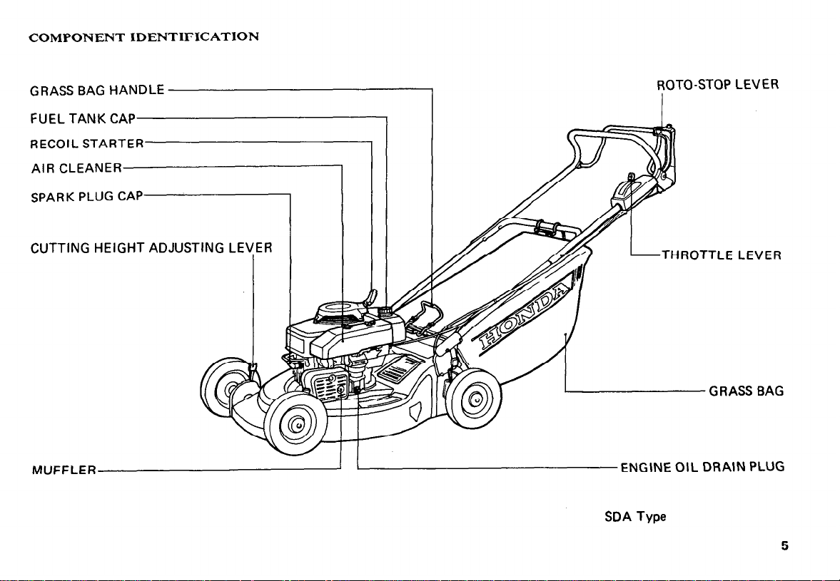
COMPONENT IDENTIFICATION
GRASS BAG HANDLE
FUEL TANK CAP
RECOIL STARTER
AIR CLEANER
SPARK
CUTTING HEIGHT ADJUSTING
MUFFLER
PLUG CAP
LEYER
ROTO-STOP LEVER
1
THROTTLE LEVER
GRASS BAG
ENGINE OIL DRAIN PLUG
SDA Type
5
Page 8
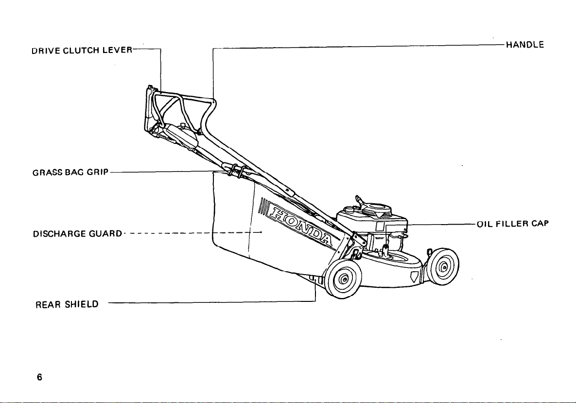
DRIVE CLUTCH LEVER
GRASS BAG GRIP
1 ~HANDLE
,,lSC..,ARGE G,,
REAR SHIELD
6
OIL FILLER CAP
Page 9
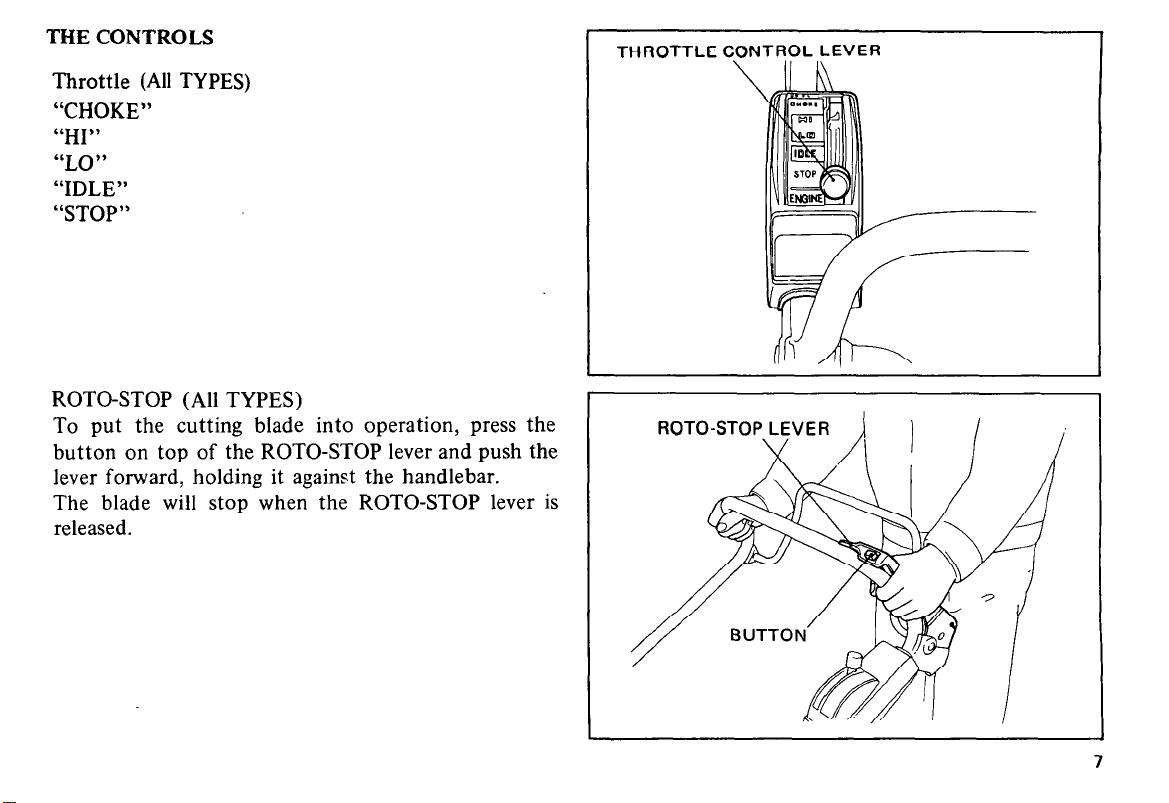
THE CONTROLS
Throttle (All TYPES)
“CHOKE”
“HI”
“LO”
“IDLE”
“STOP”
ROTO-STOP (All TYPES)
To put the cutting blade into operation, press the
button on top of the ROTO-STOP lever and push the
lever forward, holding it against the handlebar.
The blade will stop when the ROTO-STOP lever is
released.
THROTTLE CONTROL LEVER
ROTO-STOP LEVER
Page 10
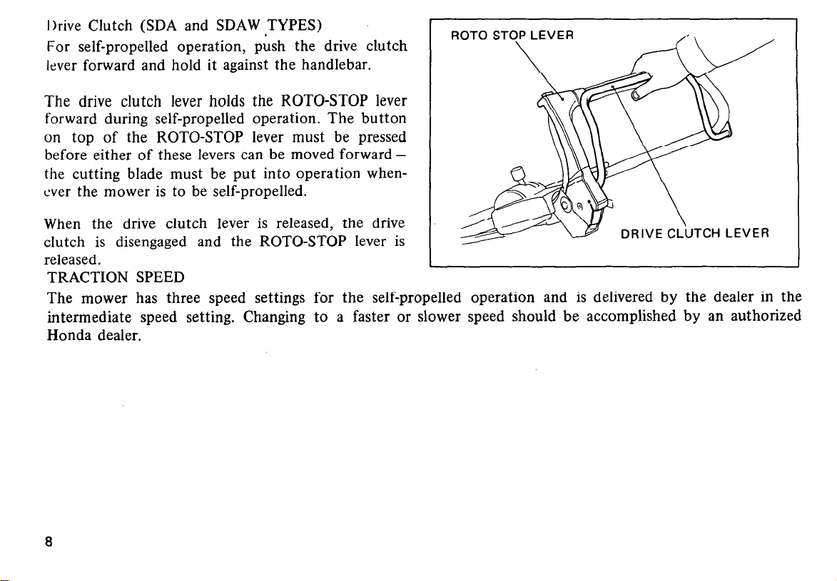
I)rive Clutch (SDA and SDAW ,TYPES)
For self-propelled operation, push the drive clutch
lever forward and hold it against the handlebar.
The drive clutch lever holds the ROTO-STOP lever
forward during self-propelled operation. The button
on top of the ROTO-STOP lever must be pressed
before either of these levers can be moved forward the cutting blade must be put into operation whenever the mower is to be self-propelled.
When the drive clutch lever is released, the drive
clutch is disengaged and the ROTO-STOP lever is
released.
TRACTION SPEED
The mower has three speed settings for the self-propelled operation and is delivered by the dealer in the
intermediate speed setting. Changing to a faster or slower speed should be accomplished by an authorized
Honda dealer.
Page 11
OPERATION
The HRA21 may be used with the grass bag or discharge adapter.
The following suggestions and rules are intended
to help you operate your Honda HRA21 under the
safest conditions possible. Be alert and exercise the
same care using the mower as you would using any
other power tool.
* Be especially careful when mowing uneven or rough
ground. The mower may tilt, exposing the blade,
and hidden objects could be thrown by the blade.
Keep all four wheels on the ground.
1
I
* Use extra care when mowing around objects to
keep the blade from striking them. Never delibera-
tely mow over any object.
* Stop the engine immediately if the blade hits an
object or the mower starts to vibrate. Remove the
spark plug cap (keep the wire away from the plug)
and inspect for damage.
NOTE:
Mow across slopes.
Do not mow excessively steep
slopes.
Always push, never pull, a mower with the engine
running.
Control direction by the handle, not by
foot pressure on the mower housing.
Keep a firm hold on the handle and walk, never
run, with the mower. Don’t lag behind the machine or let it pull you.
(SDA and SDAW TYPES) Do not use the drive
clutch when maneuvering around trees, etc. Release
the clutch and push the mower while using the
ROTO-STOP for better directional control.
Page 12
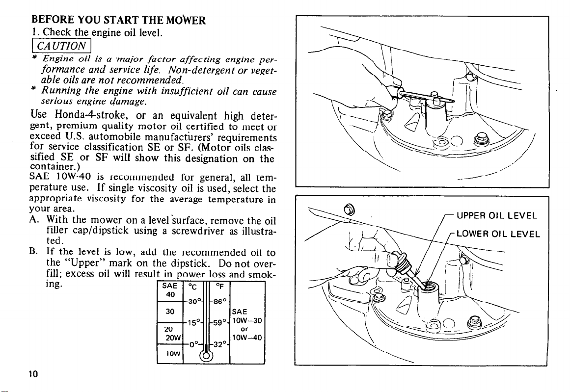
BEFORE YOU START THE MObVER
1. Check the engine oil level.
pY5V-l
* Engine oil is a .major factor affecting engine per-
formance and service life. Non-detergent or veget-
able oils are not recommended.
* Running the engine with insufficient oil can cause
serious engine damage.
Use Honda-&troke, or an equivalent high deter-
gent, premium quality motor oil certified to meet or
exceed U.S. automobile manufacturers’ requirements
for service classification SE or SF. (Motor oils classified SE or SF will show this designation on the
container.)
SAE low-40 is recommended for general, all temperature use. If single viscosity oil is used, select the
appropriate viscosity for the average temperature in
your area.
A. With the mower on a level ‘surface, remove the oil
filler cap/dipstick using a screwdriver as illustrated.
B. If the level is low, add the recommended oil to
the “Upper” mark on the dipstick. Do not overfill; excess oil will result in power loss and smok-
ing.
UPPER OIL LEVEL
LOWER OIL LEVEL
10
Page 13

2. Check the fuel level.
Use regular or unleaded automotive gasoline of 86
pump octane or higher.
Never use an oil/gasoline mixture or dirty gasoline.
Avoid getting dirt, dust or water in the fuel tank.
* Gasoline is extremely flammable and explosive un-
der certain conditions. Refuel in a well ventilated
area with the engine stopped.
* Do not smoke or allow flames or sparks in the area
where the mower is refueled or where gasoline is
stored.
* Be careful not to spill fuel when refueling. Fuel
vapor or spilled fuel may ignite. Make sure the
area is dry before starting the engine.
* Do not overfill the tank and make sure the filler
cap is securely closed after refueling.
* Refuel when the engine is cold.
-1 Gasoline substitutes, such as gasohol etc., are not
recommended, they may be harmful to the fuel system cov-
ponents.
11
Page 14

3. Check the grass bag for fraying, tears and clogged
mesh. Wash the bag with water if necessary, and
let it dry thoroughly. Grass will not chute properly without adequate ventilation through the bag.
Make sure the lock lever is latched securely.
4. Check the blade bolts for tightness.
Torque: 455.5 kg m ( 32.5-39.8 ft lb)
-
* To be certain that the engine will not start acciden-
tally, remove the spark plug cap before performing
this inspection.
5. Check and clean the air cleaner element if it is
dirty (p. 24).
12
Page 15

STARTING THE ENGINE
* Exhaust gas contains poisonous carbon monoxide.
Never run the mower in an enclosed area. Be sure
to provide adequate ventilation.
1. Move the throttle lever to “CHOKE”.
NOTE:
Do not use “CHOKE”
when the engine is warm or
the air temperature is high. Move the throttle to
“LO” instead.
2. Turn the fuel valve “ON”.
CHOKE
HROTTLE LEVER
Page 16

3. Place your foot on the “STEP” of the mower housing.
4. Pull the starter rope lightly until you feel compression,
then
pull
briskly.
NOTE:
Do not allow the rope to snap back; return it by hand.
5. After the engine warms up, move the throttle lever
to “HI”.
Squeeze the ROTO-STOP to start the
blade.
SDA and SDAW TYPES: Engage the drive clutch/
ROTO-STOP. Mower will move forward.
NOTE:
The throttle lever may be moved anywhere between
“HI” and “LO” to adjust engine speed during operation.
However the engine may stall if the lever is at “IDLE”
when the ROTO-STOP is engaged. *
’
Page 17

Flooded Engine
If the engine won’t start after several pulls on the
starter rope the engine is probably flooded.
To clear a flooded engine:
1. Move the throttle lever to “STOP” and turn off the
fuel valve.
2. Remove and dry the spark plug. When re-installing
the plug, thread it in by hand until it seats. Then
tighten it an additional l/8- l/4 turn with the spark
plug wrench to compress the washer.
3. Move the throttle to “HI”, turn on the fuel valve
and repeat steps 3-5 under “Starting the Engine”.
Stopping the Engine
1. Release the roto-stop lever.
SDA and SDAW TYPES: Release the drive clutch
lever.
2. Move the throttle lever to “STOP” and turn off
the fuel valve.
ROTTLE LEVER
Page 18

Cutting Height Adjustment
Six settings are available: S/8”, l”, l-1/2”,2”,2-1/2”,3”.
To change blade height:
1. Stop the engine.
2. Push the adjusting lever t&ward the wheel and
move it up or down to raise or lower the blade
height.
3. Release the lever in the appropriate notch.
4. Adjust the other three wheels. Make sure all four
wheels are at the same level.
* Be careful not to touch the muffler when adjust-
ing the right front wheel height.
The muffler wiN stay hot for a while after the en-
gine is stopped.
[CAUTION:
* Adiust all four wheels to the same level.
3”
lJ-===-F -w
ADJUSTING LEVER
16
Page 19

Grass Bag
The bag is subject to wear under normal usage; frequently check for fraying and tears. Replace deteriorated bags only with Honda replacement bags or
equivalent. When the bag needs cleaning, wash it
with water and make sure it is dry before using it.
Clogged mesh will result in poor grass chuting and a
wet bag will clog quickly.
Removale
q
Remove the grass bag grip from handle pipe.
a Push the door latch down.
q
Pull the grass bag rear ward while pushing the
door latch down.
Installation
‘$J Grab the grass bag handle, set the lower edge of
the bag onto the recess of the mower housing.
q
Push the grass bag handle forward until the forward end of the handle rests on the latch groove.
q
Hang the grass bag grip onto the lower handlebar.
Page 20

TRANSPORTING/STORAGE
Transporting
Turn
mower.
the fuel valve OFF when
transporting
the
* To avoid fuel and oil spillage do not tilt the unit;
spilled fuel may ignite.
Preparation for Storage
The following steps should be taken to protect the
mower whenever it will be stored for longer than 30
days.
1. Drain the fuel tank and carburetor into an approved gasoline container:
A. Remove the fuel tube and turn the fuel valve
ON to empty the fuel tank.
18
Page 21

B.
Loosen the carburetor drain bolt to drain the
carburetor.
C. Retighten the drain bolt, connect the fuel tube
and turn the fuel valve OFF.
* Gasoline is extremely flammable and explosive un-
der certain conditions. Do not smoke or allow
flames or sparks in the area.
2. Change the engine oil (p. 23).
NOTE :
If the mower will be stored for longer than a year,
remove
the spark plug and pour three tablespoonsful of clean motor oil into the cylinder. Pull
the starter rope slowly two or three times to distribute the oil.
Replace the plug.
I
DRAIN BOLT
1
I
19
Page 22

3. Pull the starter rope until resistance is felt. This
closes the valves and helps to protect the com-
bustion chamber from corrosion.
4. Remove dirt and debris from the underside of the
mower housing. Clean the mower thoroughly. Paint
areas that may rust with a rust-resistant paint, or
coat with a light film of oil.
5. Cover the mower and store it on a level surface
in a dry, dust-free area.
Removal From Storage
1. Remove the spark plug; check that it is clean and
properly gapped (p. 25). Pull the starter rope sev-
eral times.
2. Thread the spark plug in as far as possible by hand,
then use the plug wrench to tighten l/8 to l/4 turn
further.
3. Check the engine oil level and condition.
4. Fill the fuel tank and start the engine.,
NOTE:
If the cylinder was coated with oil, the engine will
smoke at start up; this is normal.
STARTER HANDLE
20
Page 23

MAINTENANCE
*
To
prevent accidental start-up, shut off the engine
and disconnect the spark plug cap before perform-
ing any maintenance.
* Use only genuine Honda parts or their equivalent
for maintenance or repair.
Replacement parts
which are not of equivalent quality may damage
the mower.
Periodic inspection and adjustment of the Honda
HRA2 1 are essential it high level performance is to be
maintained. Regular maintenance will also help to
extend service life. The required service intervals and
the kind of maintenance to be performed are des-
cribed in the chart on the following page.
For longer service and greater efficiency, keep the
underside of the mower housing clean and free of accumulated grass clippings by washing it down with a
hose after use and/or cleaning it with a wire brush
and scraper. Remove any rust and apply a rust-re-
sistant paint. Cleaning and rust prevention are especially important before seasonal storage.
21
Page 24

MAINTENANCESCHEDULE
Regular Service Period
Perform at every indicated month
or operating hour intervals,
whichever occurs first.
3ngine oil
4ir cleaner element
Check level
Change
Check
Check
Gel strainer Check
spark plug
31ade bolts (Tightness)
brass bag
Throttle cable
Clean-Adjust
Check
Check
Adjust
Drive belt Inspection
Drive clutch cable
XOTO-STOP cable
tOTO-STOP
__-
gnition timing
Valve clearance
Combustion chamber
?uel tank
Adjust
Adjust
Check
Check-Adjust
-__
Check-Adjust
C$fe;- Lap
--
Clean
Check
‘uel tube
(Replace, if
necessary)
l
Service the air cleaner more frequently when used in dusty areas.
,
Each
Use
0
0
0
0
First
1 month
20’irs.
-
0
I
I
Every
1 month
20°4rs.
0+
Every
6 months
1 OCGIrs.
0
0
0
I
,
-
0
0**
one year
3OCkS.
,
I
Every
0
0
0
0 **
0 **
0 +*
I
y
0
J
*+ These items should be serviced by an authorized Honda dealer, unless the owner has the proper tools and is mechanically proficient.
See the Honda Shop
Manual..
22
Page 25

ENGINE OIL CHANGE
Drain the oil while the engine is still warm to assure
rapid and complete draining.
1. Remove the tiller cap/dipstick using a screwdriver
as illustrated.
2. Remove the dram bolt, drain the oil, and retighten
the bolt securely.
3. Refill to the “Upper” level mark with the recommeded oil (see p. 10). Tighten-the cap securely to
prevent leakage.
I
\
II
- LOWER
OIL DdAlN
BOLT
Page 26

AIR CLEANER SERVICE
A dirty air cleaner will restrict air flow to the carbu-
retor. To prevent carburetor malfunction, service the
air cleaner frequently.
l.Remove the wing nuts and the air cleaner cover.
Remove the elements and separate them. Carefully
check both elements for holes or tears and replace
if damaged.
2.Foam element: Clean in warm soapy water, rinse
and allow to dry thoroughly. Or clean in high
flash-point solvent and allow to dry. Dip the element in clean engine oil and squeeze out all the
excess. The engine will smoke during initial startup if too much oil is left in the foam.
3. Paper element:
Tap the element lightly several
times on a hard surface to remove excess dirt, or
blow compressed air through the filter from the
inside out. Never try to brush the dirt off; brushing
will force dirt into the fibers, Clean in warm, soapy
water and rinse. Dry using compressed air blown
from the inside out, or shake the element and allow
it to air dry thoroughly. (Or clean in high flashpoint solvent, remove immediately, and allow to
dry.) Oil the outside of the paper with a light aerosol oil such as WD-40. The engine will smoke dur-
ing initial start-up if too much oil is used.
I
PAPER ELEMENT
I
WING NUTS
.---
:.
..:
I
F
FOAM ELEMENT
24
Page 27

SPARKPLUG
Standard Plugs: BMR-6A (NGK) or W20MR-U (ND)
1. Disconnect the cap and remove the spark plug.
2. Visually inspect the plug. Discard the plug if it is
heavily deposited or if the insulator is cracked or
chipped.
3. Measure the plug gap with a wire-type feeler gauge;
it should be 0.6-0.7 mm (0.024-0.028 in). If ad-
justment is necessary, bend the side electrode care-
fully.
4. Make sure the sealing washer is in good condition,
then thread the spark plug in by hand until it seats.
5. Use the wrench to tighten a new plug l/2 turn further to compress the washer. If you are reusing the
plug it should only take l/8 - l/4 turn after the
plug seats.
6. Replace the spark plug cap.
I
1
0.6-0.7
(0.024-0.028
mm
in)
25
Page 28

BLADE REMOVAL AND SHARPENING
* Wear heavy gloves CO protect your hands.
Before tilting the mower, remove the spark plug
cap.
1. Tilt the mower so the carburetor side is up.
Loosen the blade bolts to remove the blade.
* Never tilt the mower so the carburetor side is down.
It will result in hard starting.
2. Sharpen the blade cutting edges with a file. File
the top side only. Maintain the original bevel for a
fine cutting edge. File both ends evenly to maintain blade balance.
NOTE:
Use only a genuine HONDA replacement blade or
equivalent.
3. Clean away any dirt and grass from around the
blade shaft.
4. Install the blade so that the blade bolts are securely
tightened with specified torque.
Torque: 4.5 - 5.5 kg m (32.5 - 39.8 ft lb)
IJP
26
Page 29

THROTTLE CONTROL CABLE ADJUSTMENT
1. With the throttle lever in the “CHOKE” position,
the carburetor control lever should be pulled all
the way to the right. Push the control lever with
your finger to check whether it is all the way to
the right.
2. If adjustment is necessary, loosen the lock nuts and
turn them to run the adjuster up or down as required. Tighten the lock nuts and recheck the carburetor control lever position.
3. Start the engine and make sure the engine stops
when the throttle lever is moved to the “STOP”
position. Readjust the cable if necessary.
NUTS
CHOKE
OTTLE LEVER
I-
ADJUSTER
Page 30

ROTO-STOP LEVER FREE PLAY
(All TYPES)
1. Measure free play at the tip of the lever as shown;
it should be between 5 - 10 mm (3/ 16 - 3/8 in).
2. If adjustment is necessary, loosen the lock nuts and
turn them to run the adjuster up or down as re-
quired. Tighten the lock nuts and reckeck free
play.
3. Start the engine and operate the ROTO-STOP lever.
Check to be sure the blade stops when the lever
is released.
5-10mm (3/15-3/8 in)
I
I
-STOP LEVER
28
Page 31

DRIVE CLUTCH FREE PLAY
(SDA and SDAW TYPES)
1. Measure free play at the top of the lever as shown;
it should be between 7- 12 mm (9132-l 5132 in>.
2. If adjustment is necessary, loosen the lock nuts
and turn them to run the adjuster up or down as
required. Tighten the lock nuts and recheck free
play.
3. Start the engine and check to be sure the drive
clutch engages and releases properly.
7-12 mm (g/32-15/32 in)
L
Page 32

NOTE:
The following adjustments should be performed by
an authorized Honda dealer unless the owner has the
proper tools and is mechanically proficient.
1. Move the throttle lever to “IDLE” and start the
engine.
2. Turn the throttle stop screw either in or out as
required until the engine runs at 1,400 rpm.
THROTTLE STOP SCREW
30
Page 33

RASS BAG ASSEMBLY
2. Place the anti-sag rod in the bag as shown and
secure its upper sides to the upper frame with
two nuts.
,
3. Turn the bag upside down. Install the lower
frame with the lipped edge forward and secure
it with two screws as shown.
4. Insert the lower plate into the bag and secure
it to the lower frame with three bolts and
washers.
Page 34

GRA
5. Install the grass bag handle onto the upper frame
with two cap nuts as shown.
32
6. Install the grass bag grip by putting its ends in
the pivot hole on the rear end of the anti-sag rod.
Page 35

TROUBLESHOOTING CHART
Engine will not start
Hard starting or loss of power
Erratic operation
Engine overheats
I. No fuel.
2. Throttle lever in “STOP” position.
3. Spark plug wire loose or disconnected.
4. Spark plug faulty or improperly gapped (p. 25).
5. Engine flooded (p. 15).
6. Dirty air cleaner.
1. Dirt in gas tank.
2. Dirty air cleaner.
3. Water in gas tank.
4. Vent in gas cap and/or carburetor clogged.
I. Spark plug faulty or improperly gapped (p.25).
2. Dirty air cleaner.
1. Spark plug improperly gapped.
2. Dirty air cleaner.
3. Dirty cooling fins.
4. Low oil level.
5. Starter pulley clogged by grass, etc.
Excessive vibration
1. Loose blade or engine mounting hardware.
2. Blade unbalanced.
33
Page 36

SPECIFICATIONS
MODEL
ENGINE
Engine type
..................................
..................................
.............................
ROTARY MOWER HRA2
GVl50
Side valve, single-cylinder, forced air-cooled
four-stroke gasoline engine.
Displacement/Bore and stroke
Ignition timing
Ignition system
Engine oil capacity
Fuel tank capacity
Spark plug
FRAME
........................... 20” BTDC, Fixed
...........................
........................
........................
..............................
...............
Dimensions (Length x Width x Height)
. . . . . . . .
144 cc (8.8 cu in)/64 x 45 mm (2.52 x 1:77 in)
Flywheel magneto ignition
0.6 l(0.63 US qt)
1.0 1 (0.26 US gal)
BMRdA(NGK), WQOMR-U(ND)
1,585 x 540 x 975mm (62.4 x 21.3 x 38.4in)
Dry weight . . . . . . . . . . . . . . . . . . . . . . . . . . . . . . SDATYPE: 44.5 kg(98 lb)
SDAW TYPE: 43.5 kg (96 lb)
PDA TYPE: 41.5 kg(91 lb)
PDAW TYPE: 40.5 kg (89 lb)
Grass bag capacity . . . . . . . . . . . . . . . . . . . . . . . .
80Q
(2.2 bu)
Cutting width . . . . . . . . . . . . . . . . . . . . . . . . . . . . 540 mm (21 in)
1
34
Page 37

Page 38

Page 39

Page 40

 Loading...