

Page 1
Page 2
This manual covers operation and maintenance of the F200 tiller. All information in this publication
is based on the latest product information available at the time of approval for printing. Honda Motor Co.,
Ltd. reserves the right to make changes at any time without notice and without incurring any obligation. The
manual should be considered a permanent part of the tiller and remain with the tiller when sold.
Read the manual carefully. Pay special attention to statements preceded by the following words:
Indicates a strong possibility of severe personal injury or loss of life if instructions are not followed.
CAUTION:
Indicates a possibility of personal injury or equipment damage if instructions are not followed.
NOTE:
Gives helpful information.
Thank you for purchasing a Honda Tiller.
If a problem should arise, or if you have any questions about the tiller, consult an authorized Honda dealer.
The Honda tiller is designed to give safe and dependable service if operated according to instructions.
Read and understand the Owner’s Manual before operating the tiller. Failure to do so could result in personal
injury or equipment damage.
No part of this publication may be reproduced without written permission.
0 Honda Motor Co., Ltd., 1980
2
Page 3
IMPORTANT NOTICE
I
This tiller is not equipped with a spark arrester. Operation on
forest, bush or grass covered land may be illegal in some
states. Check local laws and regulations before operation.
Page 4
CONTENTS
SAFE OPERATION . . . . . . . . .
COMPONENT IDENTIFICATION
OPERATION . . . . . . . . . . . . . .
MAINTENANCE . . . . . . . . . . .
TRANSPORTING/STORAGE . .
SPECIFICATIONS . . . . . . . . . .
.......................
.......................
.......................
.......................
.......................
.......................
.......
.......
.......
.......
.......
.......
......
......
......
......
......
......
. 4
. 5
. 7
17
24
27
3
Page 5
SAFE OPERATION
B To ensure safe operation
l
Never permit anyone to operate the tiller without proper instruction.
l
Know how to stop the tiller quickly and understand the operation of all the controls - READ
THIS OWNER’S MANUAL CAREFULLY.
l
Keep children and pets at a safe distance when
tilling.
l
Clear the area to be tilled by picking up any
stones, wire, glass, large sticks, metal, etc.
l
Always stop the engine before cleaning the tines
or making adjustments.
l
Never operate the tiller without the recoil
starter.
l
Stop the engine whenever you leave the tiller.
Never allow it to idle unattended.
l
If you strike an object while tilling, stop the
engine and check the tiller for damage.
l
When tilling on an incline, keep the fuel tank less
than half full to minimize fuel spillage.
l
Make sure that all fasteners are properly secured.
l
Wear suitable clothing and shoes while using the
tiller.
l
Whenever carrying the tiller, make sure to stop
the engine; or the rotor may turn even if the
clutch is disengaged.
Page 6
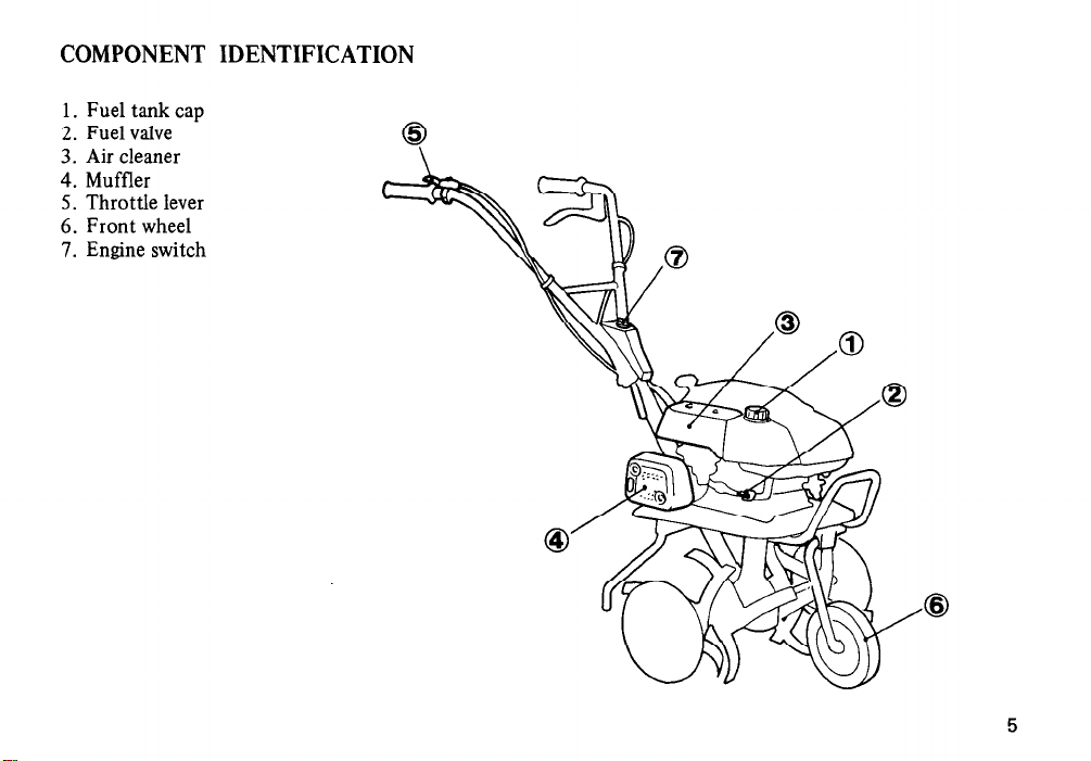
COMPONENT IDENTIFICATION
1. Fuel tank cap
2. Fuel valve
3. Air cleaner
4. Muffler
5. Throttle lever
6. Front wheel
7. Engine switch
Page 7
6
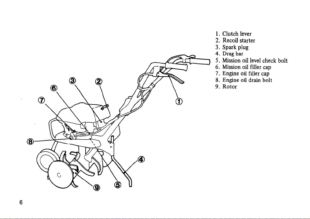
1. Clutch lever
2. Recoil starter
3. Spark plug
4. Drag bar
5. Mission oil level check bolt
6. Mission oil filler cap
7. Engine oil filler cap
Engine oil drain bolt
8.
9. Rotor
Page 8
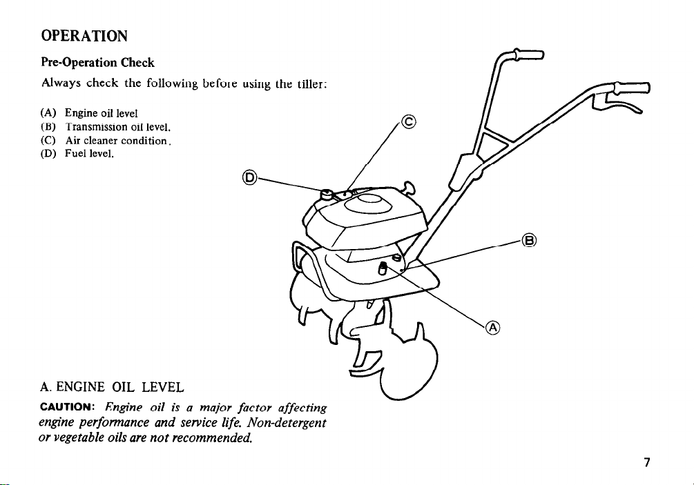
OPERATION
Pre-Operation Check
Always check the following before
using the tiller:
(A) Engine oil
level
(B) Transmission oil level.
(C) Air cleaner condition.
(D) Fuel level.
A. ENGINE OIL LEVEL
CAUTION:
engine
Engine oil is a major factor affecting
performance and service life. Non-detergent
or vegetable oils are not recommended.
7
Page 9
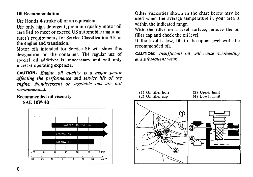
Oil Recommendation
Use Honda 4-stroke oil or an equivalent.
Use only high detergent, premium quality motor oil
certified to meet or exceed US automobile manufacturer’s requirements for Service Classification SE, in
the engine and transission.
Motor oils intended for Service SE will show this
designation on the container. The regular use of
special oil additives is unnecessary and will only
increase operating expenses.
CAUTION:
Engine oil quality is a major factor
affecting the performance and service life of the
engine.
Nondetergent or vegetable oils are not
recommended.
Recommended oil viscosity
SAE low-40
Other viscosities shown in the chart below may be
used when the average temperature in your area is
within the indicated range.
With the tiller on a level surface, remove the oil
filler cap and check the oil level.
If the level is low, fill to the upper level with the
recommended oil.
CAUTION:
Insufficient oil will cause overheating
and subsequent wear.
(1) Oil filler hole (3) Upper limit
(2) Oil filler cap
(4) Lower limit
8
Page 10

B. TRANSMISSION OIL LEVEL
With the tiller on a level surface remove the oil level
check bolt and check if the oil flows out of the
bolt hole. If the oil level is low, reffi with the
recommended oil till it flows out of the bolt hole.
C. AIR CLEANER CONDITION
Remove the cover and inspect the elements, clean
them if necessary (see p. 19).
(1) Oil level check bolt (2) Oil filler cap
(3) Air cleaner cover
(4) Air cleaner elements
9
Page 11

E. FUEL
Use any automotive gasoline with a research octane
y) of 86 or
of 91 or higher or a pump octane
(
higher.
l
Gasoline is extremely flammable and explosive
under certain conditions. Refuel in a well ventilated area with the engine stopped. Do not
smoke or allow flames or sparks in the area
where the tiller is refueled or stored.
l
Never fill the tank above the level.
CAUTION:
Gasoline substitutes are not recommended, they may be harmful to the fuel system components.
Fuel tank capacity: 0.85 Q (1.80 US pt).
(1) Fuel filler holk
10
(2) Upper level
Page 12

Starting the Engine
-
l
Exhaust contains poisonous carbon monoxide
gas. Never run the engine in a green house or
confined area. Be
sure
to provide adequate
ventilation.
l
The muffler becomes very hot during operaton,
and it remains hot for a time after the engine is
turned of5 Avoid touching a hot muffler.
l
Keep away from rotating parts while the engine
is running.
1. Turn the fuel valve ON.
2. Turn the engine switch to ON.
(1) Fuel valve
(3) Engine switch
(2) ON
Page 13

3.
Move the
choke lever to CLOSE, when the out-
side temperature is low or the engine is cold.
4. Move the throttle lever about 30 degrees from
the extreme right (idle position).
12
I
(1) Choke lever
(3) Throttle lever
(2) CLOSE
Page 14

NOTE:
The clutch is engaged by pulling in the
clutch lever and disengaged by releasing the lever.
5. Make sure the clutch is disengaged, then pull the
starter rope briskly to start the engine.
CAUTION :
l
Be sure the clutch is disengaged to prevent
sudden uncontrolled movement when the engine
starts.
l
Release the starter rope gradually. Allowing it to
snap back can damage the mechanism.
(1) Clutch lever
(3) Disengaged
(4) Starter
(2) Engaged
Page 15

6.
Allow the
enigne to warm up, then move the
choke lever to OPEN.
7. Move the throttle lever to the left as desired to
increase engine speed.
(1) OPEN
14
Page 16

Stopping the Engine
1. Disengage the clutch (release the lever).
2. Move the throttle lever to the extreme right.
3. Turn the engine switch OFF to stop the engine.
(1) Throttle lever
4. Turn the fuel valve OFF.
NOTE:
To stop the engine in an emergency, dis-
engage the clutch and turn the engine switch OFF.
(2) Engine switch (3) OFF
(4) Fuel valve
Page 17

Handlebar Height Adjustment
CAUTION:
the tiller on jim level ground to prevent the handle
Before adjusting the handlebar, place
from falling accidentally.
To adjust the handlebar height, loosen the adjuster,
select the appropriate holes and tighten the adjuster.
Tilling depth adjustment
The tilling depth adjustment can be made by removing retainer and sliding drag bar up or down as
necessary.
(1) Handle height adjuster
0
(2) Drag bar
(3) Retainer
,
16
Page 18

MAINTENANCE
m Shut off the engine
before performing any maintenance.
CAUTION: To maintain the safety
and rt%izbility of your HONDA tiller
do not mod@ the tiller. Use only
genuine HONDA parts or their
equivalent when servicing or repair-
ing.
MAINTENANCE GUIDE
Periodic inspection and adjustment
of the Honda Tiller is essential if a
high level of performance is to be
maintained.
will also insure the longest possible
life of your Honda tiller.
0 Performed by owner.
l
Should be performed by an authorized
Honda dealer unless the owner has the
proper tools and is mechanically proficient. See the Honda Shop Manual.
* Service the air cleaner more frequently
as required.
Regular
maintenance
Regular Service Period
indicated month or
interval. whichever
Engine oil
Air cleaner eleme
Spark plug Ciean
Clutch shoe Change
Ignition timing Adjust
Tappet clearance Adjust
1 Combustion chamber )
Fuel line Check
(Replace, if necessary)
Fuel strainer
(Replace, if necessary)
Fuel tank
Check level 1
(Inc. valve lapping)
Clean I
Check
Clean
Before A-
pi
operation
I I
r lrsr
Initial ”
operation operation operation operation
I.. f
I I I.1
17
Page 19

Engine Oil Change
NOTE:
Change the oil when the engine is warm to
assure rapid and complete draining.
1. Remove the oil drain bolt and the filler cap to
drain.
2. Reinstall the drain bolt and fill the crankcase to
the upper level with the recommended oil.
3. Reinstall and tighten the filler cap.
Oil capacity: 0.45 R (0.95 US pt)
18
(1) Oil filler cap
(3) Upper level (4) Lower level
(2) Oil drain bolt
Page 20

Air Cleaner Service
A dirty air cleaner will restrict air flow to the
carburetor.
To prevent carburetor malfunction, service the air
cleaner frequently.
1. Remove the screws and air cleaner cover.
Remove the elements and separate them.
2. Wash the foam element in liquid detergent and
water and flush until water is clear. Dry it
thoroughly by applying compressed air. After
drying, soak in oil and squeeze out the excess.
3. Remove dust from paper element by applying
compressed air or tapping the case lightly. If the
paper element is excessively dirty, replace or
wash it in liquid detergent and water and flush
until water is clear. Dry it thoroughly by
applying compressed air before installing.
(1)
Air
cleaner
cover (2) Foam element
(3) Paper element.
Page 21

Spark Plug Service
Recommended spark plug: BMR-4A (NGK),
W14MR-U (ND) To ensure proper engine operation,
the spark plug must be properly gapped and free of
deposits.
1. Clean any dirt from around the spark plug base.
2. Remove the plug cap and use the wrench to remove the spark plug.
3. Visually inspect the spark plug. Discard it if the
insulator is cracked or chipped.
4. Measure the plug gap with a feeler gauge. The gap
should be 0.6-0.7 mm (0.024-0.028 in). Correct
as necessary by bending the side electrode.
5. Attach the plug washer. Thread the plug in by
hand to prevent cross-threading.
6. Tighten a new spark plug l/2 turn with the
wrench to compress the washer. If you are
reusing a plug, it should only take l/8-1/4 turn
after the plug seats.
CAUTION:
l
The spark plug must be securely tightened. An
improperly tightened plug can become vev hot
and possibly damage the tiller.
l
Never use a spark plug with an improper heat
range.
(1) Spark plug wrench
I
(2) 0.6-0.7 mm (0.024-0.028 in)
20
Page 22

Throttle Cable Adjustment
Loosen the lock nut and turn the throttle cable
adjusting bolt until free play at the throttle lever is
between 5 - 10 mm (l/4-3/8 in) as shown. Tighten
the lock nut securely.
(1) Lock nut
(2) Throttle cable adjusting bolt
Page 23

Clutch Cable
1. Squeeze the clutch lever lightly until resistance is
felt (in this position, the clutch starts to engage),
and measure the clearance between the handlebar
end and the lever tip as illustrated.
Clutch lever clearance: 45-50 mm (1.77-l .97 in)
2. If the clearance is incorrect, loosen the lock nut
and turn the adjusting bolt in or out as required.
3. After adjustment, tighten the lock nut securely.
Then start the engine and check for proper
clutch lever operation.
(1) Clearance
22
(2) Lock nut
(3) Adjusting bolt
Page 24

Rotor Assembly
Install the tine assemblies and side disks as illustrated below.
NOTE:
Side disks can be installed on each side.
“L” side
> “R” side
23
Page 25

TRANSPORTING/STORAGE
Transporting
Always turn the fuel valve off when transporting the tiller.
Keep it level to avoid fuel and oil leakage, and
secure it with a suitable strap or rope.
Preparation For Storage
l
Close the IN. & EX. valves and the contact
breaker points.
Pull the starter handle until it becomes hard to
pull (the piston is coming up on the compression
stroke).
Both valves and the contact breaker points will
be closed. This will protect the valve seats and
the points from corrosion.
l
Drain the gasoline from the fuel tank and carburetor:
Remove the fuel line from the fuel valve, turn
the valve ON and dram all gasoline from the fuel
tank into metal container.
Remove the carburetor darin bolt to dram
gasoline from carburetor. Reinstall the fuel line
and tighten the dram bolt securely. Turn the fuel
valve OFF.
B Gasoline is flnmmable and explosive
under certain conditions. Do not smoke or allow
flames or sparks near the equipment while draining
fuel.
24
(Over 30 days):
(1) Carburetor drain bolt
Page 26

l
Drain the engine oil and refill the engine with
fresh oil.
l
Clean the tiller and coat areas of possible rust
with a light film of oil.
l
Coat the cylinder walls with oil. (If anticipated
storage will exceed 1 year.)
Remove the spark plug and pour two or three
tablespoonsful of clean oil into the cylinder.
Pull the starter handle slowly to distribute the
oil over the cylinder walls. Leave the piston on
compression to close the valves and points.
Reinstall the spark plug.
l
Cover the tiller and store on a level surface in
a dry, dust-free area.
l
Do not place the tiller with the handlebars on the
ground. It will cause the oil entering the cylinder
or the fuel spillage.
25
Page 27

Removal From Storage
l
Remove the spark plug and pull the starter handle several times.
l
Check that the spark plug is clean and properly gapped, then reinstall and tighten the
l
Check engine and transmission oil levels.
NOTE:
Oil will deteriorate if left in an engine for a long period of time. Change the engine oil if the tiller
has been stored for several times.
l
Fill the fuel tank.
plug.
B
Gasoline is flammable and explosive under certain conditions. Do not smoke or allow flames or
sparks near the equipment while filling tank. Fill the fuel tank only in a well ventilated area.
l
Check operation and condition of all controls. (If any parts are required, use only genuine Honda parts or
their equivalent).
l
Turn the fuel valve ON, start the engine and check operation. (Note: If the cylinder was oiled for storage,
the engine will smoke for a while after it starts. This will clear up.)
26
Page 28

SPECIFICATIONS
Model
.........................
Dimensions(LxWxH).
Dry weight.
Maximum handle height
Engine
Model.
Type
Displacement/Bore and stroke
Ignition timing
Ignition system
Enigne oil capacity
Fuel tank capacity.
Spark plug.
Clutch.
Transmission
Oil capacity
.....................
.............
......................
........................
.................
.................
..............
..............
...................
........................
....................
...................
............
.F200
.1,250 x 585 x 960 mm (49.2 x 23.0 x 37.8 in)
.27.0 kg (59.5 lb)
.I ,045 mm (41 .I in)
.GlOO
Single cylinder, 4-stroke, forced air cooled, side valve, gasoline
....... .76
.20”B.T.D.C.
.Flywheel magneto
.0.45 II (0.95 US pt)
.0.85 8 (1.80 US pt)
.BMR4A (NGK), W14MR-U (ND)
Internal expanding shoe
Planetary gear
.0.95 II (2.01 US pt)
cm3 (4.6 cu in)/46 x 46 mm (1.81 x 1.81 in)
27
Page 29

Warranty Service
Owner Satisfaction
Your satisfaction and goodwill are important to your dealer and to us. Normally, any problems with the product will be handled by your dealer’s service department. Sometimes, however, despite the best intentions
of all concerned, misunderstandings can occur. If your problem has not been handled to your satisfaction,
we suggest you take the following action:
l
Discuss your problem with a member of dealership management. Often complaints can be quickly resolved at that level. If the problem has already beeh reviewed with the Service Manager, contact the
owner of the dealership or the General Manager.
l
If your problem still has not been resolved to your satisfaction, contact the Customer Relations Department
at the regional office of American Honda Motor Co., Inc. in your area. Regional office locations are shown
on the following page. We will need the following information in order to assist you.
-Your name, address, and telephone number
-Product model and serial number
-Date of purchase
-Dealer name and address
-Nature of the problem
After reviewing all the facts involved, you will be advised of what action can be taken. Please bear in mind
that your problem will likely be resolved at the dealership, using the dealer’s facilities, equipment, and personnel, so it is very important that your initial contact be with the dealer.
Your purchase of a Honda product is greatly appreciated by both the dealer and American Honda Motor Co.,
Inc. We want to assist you in every way possible to assure your complete satisfaction with your purchase.
28
Page 30

 Loading...