

Page 1
Page 2

Page 3
Thank you for purchasing a Honda generator.
This manual covers operation and maintenance of the EB3000 and EB4000
generators. All information in this publication is based on the latest product
information available at the time of approval for printing.
Honda Motor Co., Ltd. reserves the right to make changes at any time without
notice and without incurring any obligation.
No part of this publication may be reproduced without written permission.
This manual should be considered a permanent part of the generator and
remain with the generator when sold.
Pay special attention to statements preceded by the following words:
B Indicates a strong possibility of severe personal injury or loss of
life if instructions are not followed.
CAUTION: Indicates a possibility of personal injury or equipment damage if
instructions are not followed.
NOTE: Gives helpful information.
If a problem should arise, or if you have any questions about the generator,
consult an authorized Honda dealer.
B The Honda generator is designed to give safe and dependable
service if operated according to instructions. Read and understand the
Owner’s Manual before operating the generator. Failure to do so could result
in personal injury or equipment damage.
Page 4
CONTENTS
CONTENTS
...............................
..
1. GENERATOR SAFETY
2. COMPONENT IDENTIFICATION
3. PRE-OPERATION CHECK
4. STARTING THE ENGINE
5. GENERATOR USE
6. STOPPING THE ENGINE
7.MAlNTENANCE .........................................
8. TRANSPORTING/STORAGE
9. TROUBLESHOOTING
10. SPECIFICATIONS
Il. WIRING DIAGRAM
12. HANGER KIT INSTALLATION ..................................
.......................................
........................................
.:
............................ 2
.................................
.................................. 8
.................................. 13
...............................
.................................... 26
.......................................
1
4
11
16
24
29
30
31
Page 5
1. GENERATOR SAFETY
To ensure safe operation -
l
Place the generator at least 1 m (3 ft) away from buildings or other
equipment when operating the generator.
l
Operate the generator on a level surface.
If the generator is tilted, fuel spillage may result.
l
Exhaust gas contains poisonous carbon monoxide.
Never run the generator in an enclosed area.
Be sure to provide adequate ventilation.
l
Know how to stop the generator quickly and understand operation of all
the controls. Never permit anyone to operate the generator without proper
instructions.
l
Keep children and pets away from the generator when it is in operation.
l
Keep away from rotating parts while the generator is running.
l
The generator is a potential source of electrical shocks when misued; do not
operate with wet hands.
Do not operate the generator in rain or snow and do not let it get wet.
Page 6
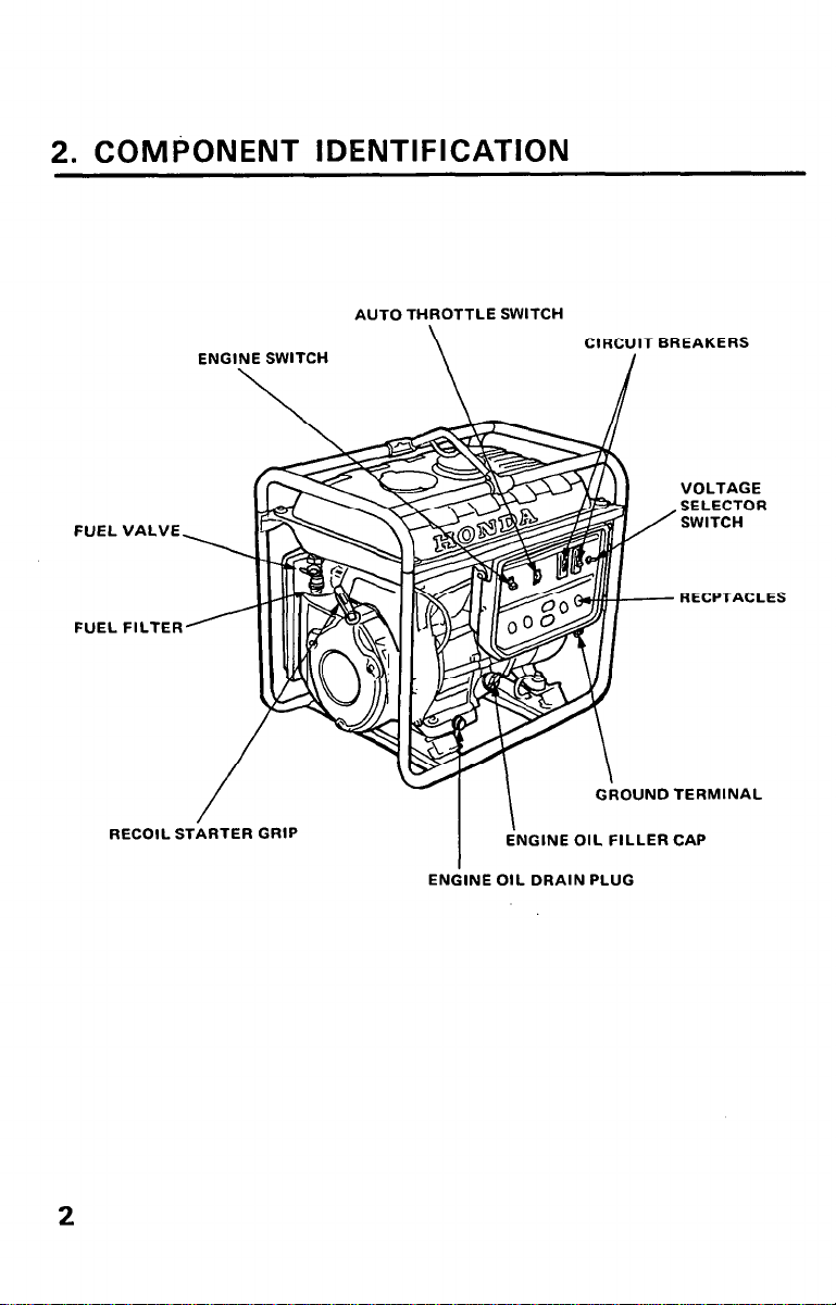
2. COMPONENT IDENTIFICATION
AUTO THROTTLE SWITCH
\
FUEL
FUEL
ENGINE SWITCH
\
VALVE
FILTER
CIRCUIT BREAKERS
VOLTAGE
SELECTOR
SWITCH
RECPTACLES
RECOIL SThRTER
2
GRIP
ENGINE OIL FILLER CAP
I
ENGINE OIL DRAIN PLUG
OUNO TERMINAL
Page 7
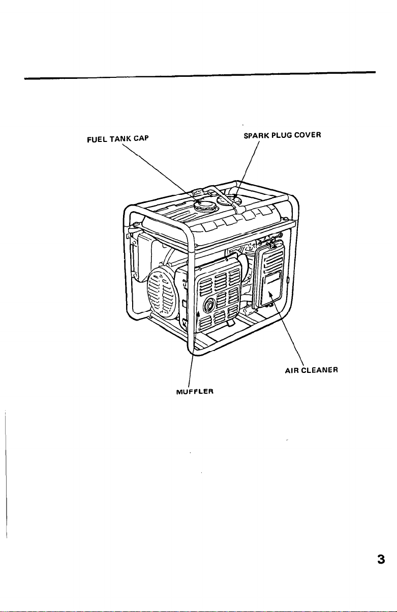
FUEL TANK CAP
SPARK PLUG COVER
\
I
MUFFLER
/
AIR CLEANER
3
Page 8
3. PRE-OPERATION CHECK
CAUTION: Be sure to check the generator on a level surface with the engine
stopped.
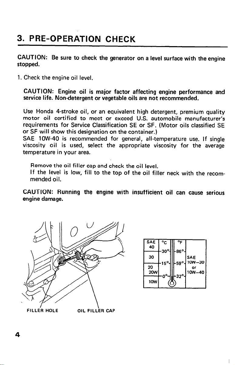
1. Check the engine oil level,
CAUTION: Engine oil is major factor affecting engine performance and
service life. Non-detergent or vegetable oils are not recommended.
Use Honda 4-stroke oil, or an equivalent high detergent, premium quality
motor oil certified to meet or exceed U.S. automobile manufacturer’s
requirements for Service Classification SE or SF. (Motor oils classified SE
or SF will show this designation on the container.)
SAE low-40 is recommended for general, all-temperature use. If single
viscosity oil is used, select the appropriate viscosity for the average
temperature in your area.
Remove the oil filler cap and check the oil level.
If the level is low, fill to the top of the oil filler neck with the recommended oil.
CAUTION: Running the engine with insufficient oil can cause serious
engine damage.
Page 9
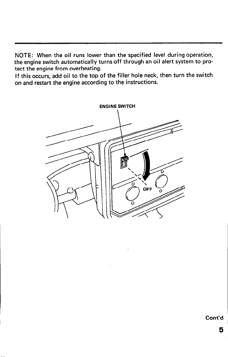
NOTE: When the oil runs lower than the specified level during operation,
the engine switch automatically turns off through an oil alert system to pro-
tect the engine from overheating.
If this occurs, add oil to the top of the filler hole neck, then turn the switch
on and restart the engine according to the instructions.
ENGINE SWITCH
Cont’d
5
Page 10
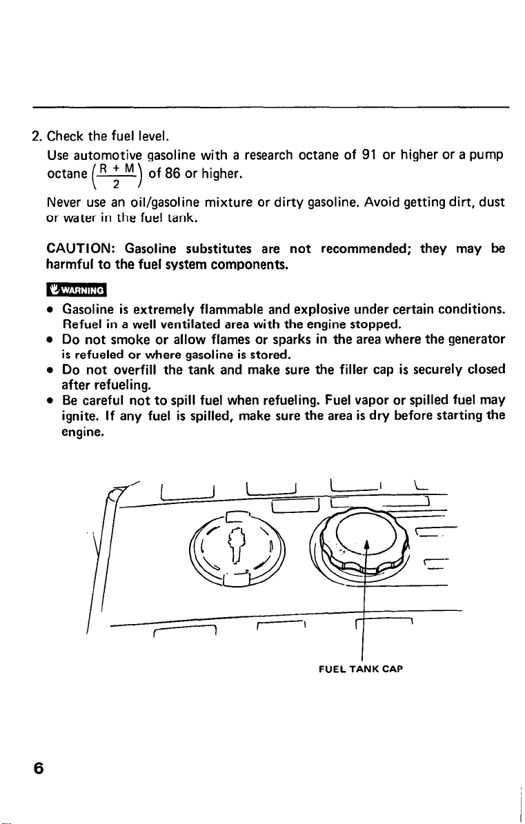
2. Check the fuel level.
Use automotive gasoline with a research octane of 91 or higher or a pump
octane of 86 or higher.
Never use an oil/gasoline mixture or dirty gasoline. Avoid getting dirt, dust
or water in the fuel tank.
CAUTION: Gasoline substitutes are not recommended; they may be
harmful to the fuel system components.
Gasoline is extremely flammable and explosive under certain conditions.
Refuel in a well ventilated area with the engine stopped.
Do not smoke or allow flames or sparks in the area where the generator
is refueled or where gasoline is stored.
Do not overfill the tank and make sure the filler cap is securely closed
after refueling.
Be careful not to spill fuel when refueling. Fuel vapor or spilled fuel may
ignite. If any fuel is spilled, make sure the area is dry before starting the
engine.
6
FUEL TANK CAP
Page 11
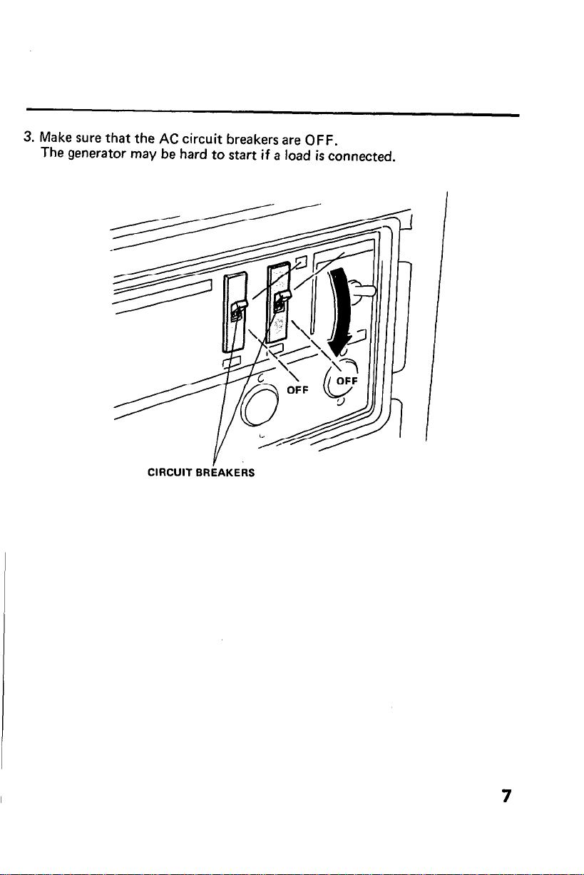
3. Make sure that the AC circuit breakers are OFF.
The generator may be hard to start if a load is connected.
CIRCUIT BRhAKERS
7
Page 12
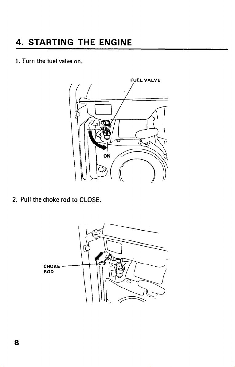
4. STARTING THE ENGINE
1. Turn the fuel valve on.
2. Pull the choke rod to CLOSE.
FUEL VALVE
,
8
CHOKE
ROD
Page 13

3* Make Sure the auto-throttle switch is off, or more time will be required for
warm
up.
AUTO-THROTTLE SWITCH
4. Turn the engine switch on.
ENGfNE SWITCH
\
9
Page 14

5. Pull the starter grip until compression is felt, then pull briskly.
NOTE: Do not allow the starter grip to snap back. Return it slowly by
hand.
6. Push the choke rod to OPEN as the engine warms up.
CHOKE ROD
STARTER
GRIP
7. If auto-throttle will be used, turn the switch to “AUTO” after the engine
has warmed up.
10
Page 15

5. GENERATOR USE
m To prevent electrical shock from faulty appliances, the generator
should be grounded. Connect a length of heavy wire between the ground
terminal and the ground source.
CAUTION:
l
Limit operation requiring maximum power (EB3000 : 3.0 kVA, EB4000 :
4.0 kVA) to 30 minutes.
For continuous operation, do not exceed the rated power of 2.8 kVA
(EB3000) and 3.8 kVA (EB4000).
In either case, the total wattage of all appliances connected must be
considered.
l
Do not exceed the current limit specified for any one receptacle.
l
Do not connect the generator to a household circuit. This could cause
damage to the generator or to electrical appliances in the house.
Auto-throttle system
With the switch in the AUTO position, engine speed is automatically reduced
to an idle when all loads are turned off or disconnected. When appliances are
turned on or reconnected, the engine resumes the rated speed. At OFF, the
auto-throttle system does not operate.
NOTE:
l
AUTO is recommended to minimize fuel consumption.
l
The auto-throttle system will not respond to electrical loads of less than 1
ampere.
l
The system is not effective for use with appliance that require only
momentary power. To avoid extended warm-up periods, keep the switch
OFF until the engine reaches operating temperature.
11
Page 16

AC applications
1. Turn the voltage selector switch to either position as required. When the
switch is turned to “12OV ONLY” position, you can use only 12OV AC. At
“12OV/24OV” position, you can use both 12OV and 240V sources.
2. Switch on the AC Circuit Breakers.
3. Plug in the appliance.
NOTE: This generator is equipped with an AVR (Automatic Voltage
Regulator) for stable voltage supply.
CAUTION: Be sure that appliances do not exceed the rated load for more
than 30 minutes, and never exceed the maximum load. Substantial
overloading will switch off the circuit breaker. Lesser overloading will not
switch off the circuit breaker and will shorten the service life of the
generator.
12
Page 17

6. STOPPING THE ENGINE
To stop the engine in an emergency, turn the engine switch OFF.
In normal use:
1. Turn the AC circuit breakers OFF.
2. Turn the engine switch OFF.
ENGINE SWITCH
13
Page 18

3. Turn the fuel valve OFF.
FUEL VALVE
14
Page 19

7. MAINTENANCE
The purpose of the maintenance schedule and adjustment is to keep the
generator in the best operating condition.
Inspect or service as scheduled in the table on the next page.
M Shut off the engine before performing any maintenance. If the
engine must be run, make sure the area is well ventilated. The exhaust
contains poisonous carbon monoxide gas.
CAUTION: Use only genuine HONDA parts or their equivalent. The use of
replacement parts which are not of equivalent quality may damage the
generator.
15
Page 20

Maintenance Schedule
REGULAR SERVICE
3 months
Inspection 0
Engine oil
Change
Air cleaner
element
Fuel filter cleaning 0
Spark plug maintenance 0
Valve clearance adjustment
Combustion chamber and
valve cleaning
Fuel line inspection
(Replace if necessary)
Spark arrester
Inspection 0
Cleaning
0 0
0 (1)
Clean every 100 operating hours.
6 months
year
0 (2)
0 (2)
0
NOTE (1) : Service more frequently when used in dusty areas.
.(2) : These items should be serviced by an authorized Honda dealer, unless the
owner has the proper tools and is mechanically proficient. See the Honda
Shop Manual.
16
Page 21

Tool kit
The tools supplied are necessary for performing some periodic maintenance,
simple adjustments and repairs.
Always keep the kit with the generator.
Changing oil
Drain the oil while the engine is still warm to assure rapid and complete
draining.
1. Remove the drain plug and filler cap, and drain the oil. Retighten the plug
securely.
2. Refill with the recommended oil (see page 4) and check the level.
OIL FILLER CAP
47
Page 22

Air cleaner service
A dirty air cleaner will restrict air flow to the carburetor. To prevent
carburetor malfunction, service the air cleaner regularly (page 16). Service
more frequently when operating the generator in extremely dusty areas.
m Never use gasoline or low flash point solvents for cleaning the air
cleaner element. A fire or explosion could result.
CAUTION: Never run the generator without the air cleaner. Rapid engine
wear may result.
1. Unsnap the clips, remove the air cleaner cover and remove the element.
ELEMENT
Page 23

2. Wash the element in a non-flammable or high flash point solvent and dry it
thoroughly.
3. Soak the element in clean engine oil and squeeze out the excess oil.
4. Reinstall the air cleaner element and the cover.
ELEMENT
19
Page 24

Fuel filter service
The filter prevents dirt or water which may be in the fuel tank from entering
the carburetor. If the engine has not been run for a long time, the filter should
be cleaned.
1. Turn the fuel valve OFF. Remove the filter cup.
2. Clean the cup thoroughly.
3. Reassemble. Do not damage the rubber gasket.
m After installing the filter cup, check for fuel leaks and make sure
the area is dry before starting the engine.
FUEL VALVE
Page 25

Spark plug service
Recommended spark plug: BR4HS (NGK)
W14FSR-U (ND)
To ensure proper engine operation, the spark plug must be properly gapped
and free of deposits.
1. Remove the spark plug cover.
2. Clean any dirt from around the spark plug base.
3. Remove the spark plug cap.
SPARK PLUG COVER
PLUG CAP
27
Page 26

4. Use the wrench supplied in the tool kit to remove the spark plug.
5. Visually inspect the spark plug. Discard it if the insulator is cracked or
chipped.
6. Measure the plug gap with a feeler gauge.
The gap should be 0.6-0.7 mm (0.024-0.028 in). Correct as necessary by
bending the side electrode.
7. Attach the plug washer. Thread the plug in by hand to prevent
cross-threading.
8. Tighten a new spark plug l/2 turn with the wrench to compress the washer.
If you are reusing a plug, it should only take l/8-1/4 turn after the plug
seats.
CAUTION:
l
The spark plug must be securely tightened. An improperly tightened plug
can become very hot and possibly damage the generator.
l
Never use a spark plug with an improper heat range.
22
PLUG WRENCH
N
-
=
! I
PLUG
1
GAP
f
0.6-0.7 mm
(0.024-0.028 in)
Page 27

Spark arrester maintenance
bxw If the generator has been running, the muffler will be very hot.
Allow it to cool before proceeding.
CAUTION: The spark arrester must be serviced every 100 hours to maintain
its efficiency.
1. Loosen the bolts and nuts and remove the muffler.
2. Loosen two 8 mm bolts to remove the exhaust pipe.
3. Check the muffler exhaust port for carbon deposits; clean if necessary.
4. Remove the spark arrester from the muffler.
Clean the screen and inspect it for damage. Replace if necessary.
5. Install the spark arrester in the muffler.
Install the muffler and gasket and tighten the bolts and nuts securely.
MUFFLER PROTECTOR
/
V
6 mm BOLTS
m NUTS
EXHAUST PIPE
MUFFLER
SPARK’ARRESTER
8 mm BOLTS
23
Page 28

8. TRANSPORTING/STORAGE
m When transporting the generator, turn the engine switch OFF and
keep the generator level to prevent fuel spillage. Fuel vapor or spilled fuel may
ignite.
Before storing the unit for an extended period:
1. Be sure the storage area is free of excessive humidity and dust.
2. Drain the fuel a. With the fuel valve OFF, remove and empty the filter cup.
b. Turn the fuel valve ON and drain the gasoline in the fuel tank into a
suitable container.
c. Replace the filter cup and tighten securely.
24
FI’iTER CUP
Page 29

d. Drain the carburetor by loosening the drain screw. Drain the gasoline
into a suitable container.
DRAIN
SCREW
e. Pull the starter grip until resistance is felt; the piston is coming up on its
compression stroke. At this position, the exhaust and intake valves are
closed, and this will help protect the engine from corrosion.
STARTER
GRIP’
25
Page 30

9. TROUBLESHOOTING
A. When the engine will not start:
1, Is there enough fuel?
2. Is the fuel valve on?
3. Is gasoline reaching the carburetor?
To check, loosen the drain screw with the fuel valve on.
h-1 If any fuel is spilled, make sure the area is dry before testing
the spark plug or starting the engine. Fuel vapor or spilled fuel may
ignite.
DRAIN SCREW
I
4. Is there enough oil in the crankcase?
5. Is the AC circuit breaker off and nothing connected to the DC
terminals?
6. Is the engine switch on?
7. Is there a spark at the spark plug (page 27)?
26
Page 31

a. Remove the spark plug cover and cap. Clean any dirt form around
the spark plug base, then remove the spark plug.
b. Install the spark plug in the plug cap.
c. Turn the engine switch on.
d. Grounding the side electrode to the stay, pull the recoil starter to see
if sparks jump across the gap.
ENGINE
GROUNDING -
STAY
STARTER
GRIP
SWITCH
e. If there are no sparks, replace the plug.
If OK, try to start the engine according to the instructions.
8. If the engine still does not start, take the generator to the dealer.
27
Page 32

B. When the engine starts but stops immediately:
Is there enough oil in the crankcase?
If not, the engine switch will turn off after starting.
C. No electricity at the AC receptacles:
1. Is the AC circuit breaker on?
2. Check the electrical appliance or equipment for any defects.
28
Page 33

Dimensions
Length x Width x Height
Dry weight
Engine
Model
Engine Type
Displacement
[Bore x Stroke1
Compression Ratio
Engine Speed
Cooling System
Ignition System
Oil Capacity
Fuel Tank Capacity
Spark Plug
I
10. SPECIFICATIONS
EB3000 : 605 x 425 x 620 mm
EB4000 : 650 x 425 x 650 mm
EB3000 : 64.5 kg (142.2 lb),
EB4000 : 81.5 kg (179.7 lb)
Honda G E300
4Stroke, side valve, 1 cylinder
272
cm3
(16.6 cu in)
[76x60mm (3.0x2.4 in)]
6.5 : 1
3,600 rpm
Forced air cooling
Flywheel magneto
1.2 Q (5.1 us qt)
16.5 Q (4.4 US gal)
BR4HS (NGK)
W14FSR-U (ND)
(23.8 x 16.7 x 24.4 in)
(25.6 x 16.7 x 25.6 in)
Honda G E400
1 406 cm3 (24.8 cu in)
[86x70mm (3.4x2.8 in)]
6.8 : 1
Generator
AC output
Rated voltage
Rated frequency
Rated ampere
Rated output
Maximum output
120 VI240 V
60 Hz
EB3000 : 23.5/l 2A
EB4000 : 32/16A
EB3000 : 2.8 kVA (2800 WI
EB4000 : 3.8 kVA (3800 W)
EB3000 : 3.0 kVA (3000 W)
EB4000 : 4.0 kVA (4000 W)
29
Page 34

IZOV/ZUIV-1 -12OV ONLY
----- ---------- ____
t
R ......... RED
G ......... GREEN
GREEN
Lg ......... LIGHT
w ......... WH,TE
TERMINAL ,
GROUND ,
e ......... BLACK
I I
VALVE
KM CONTROL
r- ----- -------------
CONTROL BOX
i I
---------------------~
GLNtRATOR
Page 35

12. HANGER KIT INSTALLATION
6 mm BOLT
HANGER
I
CAUTION: Be sure to set the hanger at the position as illustrated below.
HANGER
/
SPARK PLUG COVER
J\
FUEt TANK CAP
i
31
Page 36

32
Page 37

MEMO
33
Page 38

MEMO
34
Page 39

Page 40

 Loading...