

Page 1
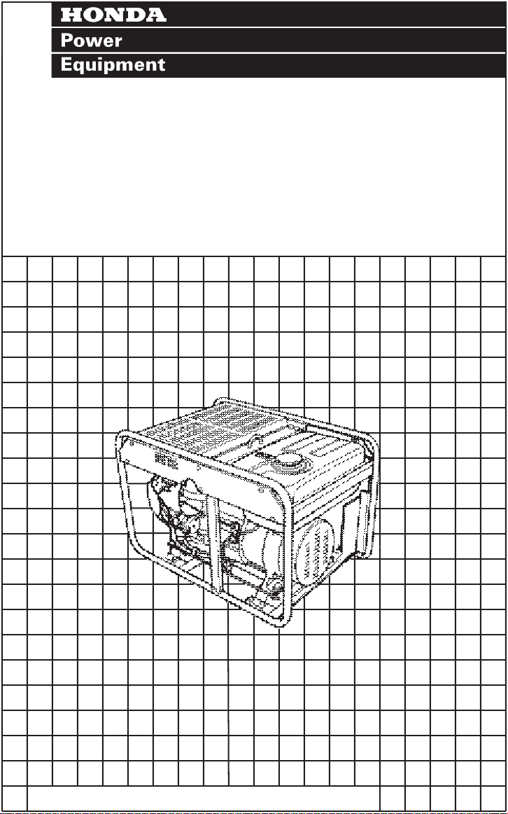
Owner's Manual
EN2000 • EN2500
EB11000
©1996 American Honda Motor Co., Inc. — All Rights Reserved
Page 2
The generator is a potential source of electrical shock if misused.
’
Do not expose the generator to moisture, rain or snow. Do not let
the generator get wet, and do not operate it with wet hands.
defects or other reproductive harm.
.
Page 3
Thank you for purchasing a Honda generator. We want to help you
get the best results from your new generator and to operate it safely.
This manual contains the information on how to do that; please read
it carefully.
This owner’s manual describes the operation and maintenance of the
Honda EBl 1000 Generator. All information,in this publication is
based on the latest product information available at the time of
printing. AMERICAN HONDA MOTOR CO., INC. reserves the right to
make changes at any time without notice and without incurring any
obligation. No part of this publication may be reproduced without
written permission.
This manual should be considered a permanent part of the generator
and should remain with it if it is resold.
Safety Messages
Your safety and the safety of others is very important. We have
provided important safety messages in this manual and on the genera-
tor. Pleasa read these messages carefully.
A safety message alerts you to potential hazards that could hurt you
or others. Each safety message is preceded by a safety alert symbol
and one of three words: DANGER, WARNING, or CAUTION.
!
-Q
ese mean:
m You WILL be KILLED or SERIOUSLY HURT if you
don’t follow instructions.
B You CAN be KILLED or SERIOUSLY HURT if you
don’t follow instructions.
B
Each message tells you what the hazard is, what can happen, and
what you can do to avoid or reduce injury.
Damage Prevention Messages
You will also see other important messages that are preceded. by the
word NOTICE.
This word means:
[W]
*
The purpose of these messages is to help prevent damage to your
generator, other property, or the environment.
You CAN be HURT if you don’t follow instructions.
y.
ur generator or other property could be damaged if you
don’t follow instructions.
1
Page 4
CONTENTS
SAFETY
Safety Label Locations
Safety Information
COMPONENT IDENTIFICATION
CONTROLS
Engine Switch
Recoie Starter
Fuel Valve
Choke KnoB
Circuit Breaker
Circuit protector
Ground Fault Circuit Interrupter (GFCI) Receptacle
Hour Meter.. ...........................................................................
Auto-throttle Switch
Ground Terminal
Oil Alert System
GENERATOR USE
Connections to a Building’s Electrical System
Ground System
Special Requirements..
AC Applications
AC Operation -
How to Use the Receptacles
Auto-throttle System
High Altitude Operation
PRE-OPERATION CHECK
Engine Oil
Fuel
Air Cleaner
STARTING THE ENGINE
STOPPING THE ENGINE
.......................................................................................
...............................................................
.....................................................................
...................................................
..............................................................................
........................................................................
........................................................................ 11
..............................................................................
...........................................................................
........................................................................
.....................................................................
...............................................................
......................................................................
.....................................................................
.....................................................................
...........................
........................................................................
.............................................................
.....................................................................
..........
.................................................................................
.......................................................................................
..............................................................................
................................................................. 21
...................................................
..................................................
.........................................................
.........................................................
............................................................
............................................................
..................
............. z
4
4
i?i
11
11
:2’
13
1:
.17
17
18
18
19
19
::
20
E
I:
ii
31
2
Page 5
MAINTENANCE
Importance
Maintenance safety
Emission Control
Proper Maintenance is the Owner’s Responsibility
Maintenance Schedule
Engine Oil Change
Oil Filter Change
Air Cleaner Service
Spark Plug Service
Spark Arrester Maintenance
Fuel Sediment Cup Cleaning
Fuel Filter
Fuse Replacement
Battery
TRANSPORTING
TROUBLESHOOTING
WIRING DIAGRAM
SPECIFICATIONS
WARRANTY SERVICE INFORMATION
INDEX
....................................................................................
.......................................................................................
........................................................................
of Maintenance..
..................................................................
System
..................................................................
.....................................................................
..................................................................
..................................................................
..............................................................................
..................................................................
STORAGE..
AND
..................................................................
.........................................................
.................................................................... .57
....................................................
.........................................................
........................................................... .36
...................................................
...................................................
..............................................
.......................................
................
............ :;
32
32
33
..: 2
37
z:
41
43
ti
t;
51
3
Page 6
SAFETY
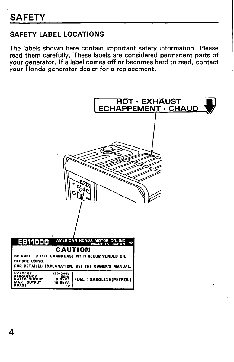
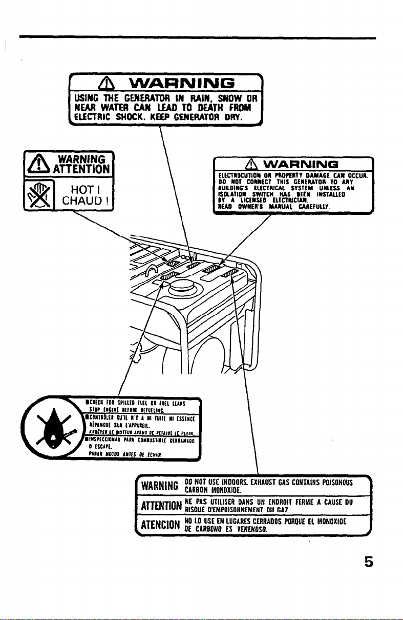
SAFETY LABEL LOCATIONS
The labels shown here contain important safety information. Please
read them carefully, These labels are considered permanent parts of
your generator. If a label comes off or becomes hard to read, contact
your Honda generator dealer for a repiacement.
BE SURE 10 FILL CRANKCASE WITH RECOMMENDED OIL
BEFORE USING.
FOR DETAILED
“OLTAGE
FREQUENCY
RATED OUTPUT
yLEOUVPUT
EXPLANATION. SEE THE OWNER’S MANUAL.
4
Page 7
OlUltCT THIS CENEMTOII I
ElECTRlrA SYSTlY UNLE
SWITCH IUS BEtbl IYSTA
‘WARN,NC 00 NOT USE INOOOAS. EXHAUST GAS CONTAINS POISUNOUS
A~~,ON NE PAS UTILISER DANS UN ENDROll FLRME A CAUSE DU
ATENCjON NO 10 USE EN LUGARES CERRAOOS POROUE EL MONOXIDE
CARBON
MONOXIDE.
RISOUE D’EMPOISONNEMENT OU CAZ.
OE CARBON0 ES VENENOSO.
-
Page 8
SAFETY INFORMATION
Honda generators are designed to give safe and dependable service if
operated according to instructions. Read and understand this owner’
s manual before operating your generator. You can help prevent
accidents by being familiar with your generator’s controls, and by
observing safe operating procedures.
Operator Responsibility
l
Know how to stop the generator quickly in case of emergency.
l
Understand the use of all generator controls, output receptacles,
and connections.
l
Be sure that anyone who operates the generator receives proper
instruction. Do not let children operate the generator without
parental supervision.
Carbon Monoxide Hazards
l
Exhaust contains poisonous carbon monoxide, a colorless and
odorless gas. Breathing exhaust can cause loss of consciousness
and may lead to death.
l
If you run the generator in an area that is confined, or even partially
enclosed, the air you breathe could contain a dangerous amount of
exhaust gas. To keep exhaust gas from building up, provide adequate ventilation.
6
Page 9
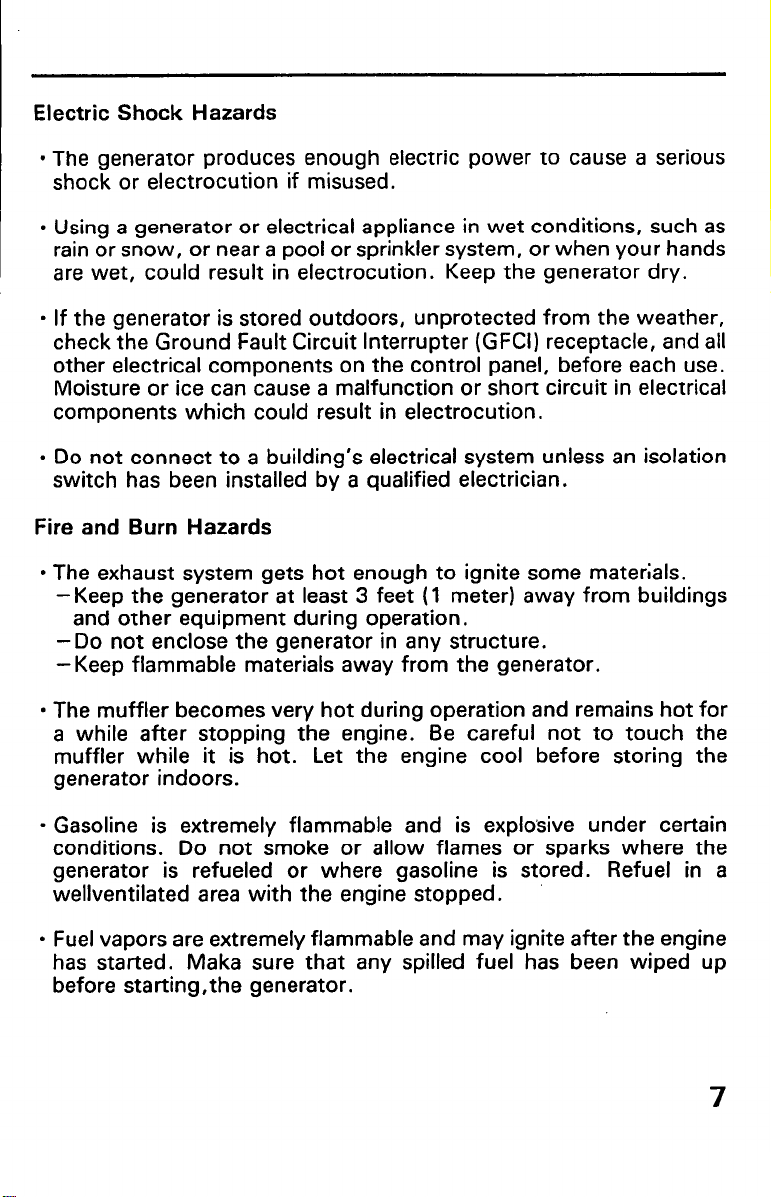
Electric Shock Hazards
. The generator produces enough electric power to cause a serious
shock or electrocution if misused.
l
Using a generator or electrical appliance in wet conditions, such as
rain or snow, or near a pool or sprinkler system, or when your hands
are wet, could result in electrocution. Keep the generator dry.
l
If the generator is stored outdoors, unprotected from the weather,
check the Ground Fault Circuit Interrupter (GFCI) receptacle, and all
other electrical components on the control panel, before each use.
Moisture or ice can cause a malfunction or short circuit in electrical
components which could result in electrocution.
l
Do not connect to a building’s electrical system unless an isolation
switch has been installed by a qualified electrician.
Fire and Burn Hazards
l
The exhaust system gets hot enough to ignite some materials.
-Keep the generator at least 3 feet (1 meter) away from buildings
and other equipment during operation.
-Do not enclose the generator in any structure.
-Keep flammable materials away from the generator.
l
The muffler becomes very hot during operation and remains hot for
a while after stopping the engine. Be careful not to touch the
muffler while it is hot. Let the engine cool before storing the
generator indoors.
. Gasoline is extremely flammable and is explosive under certain
conditions. Do not smoke or allow flames or sparks where the
generator is refueled or where gasoline is stored. Refuel in a
wellventilated area with the engine stopped.
l
Fuel vapors are extremely flammable and may ignite after the engine
has started. Maka sure that any spilled fuel has been wiped up
before starting,the generator.
7
Page 10
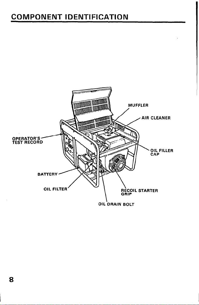
COMPONENT IDENTIFICATION
AIR CLEANER
OIL FILLER
CAP
8
, FILTER
\
\
OIL‘DRAIN BOLT
RiCOIL STARTER
GRID
Y....
Page 11
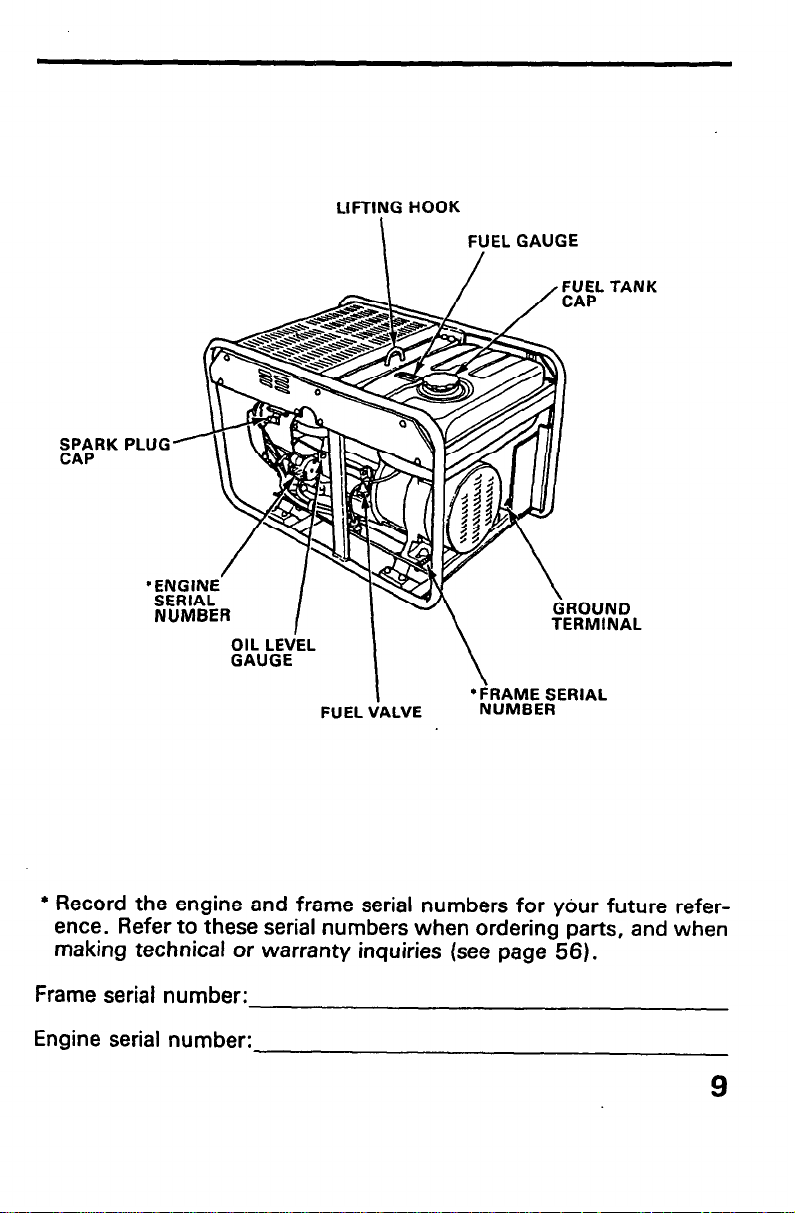
LIFTII!lG HOOK
I
FUEL VALVE
FUEL TANK
ND
NAL
l
Record the engine and frame serial numbers for ydur future reference. Refer to these serial numbers when ordering parts, and when
making technical or warranty inquiries (see page 56).
Frame serial number:
Engine serial number:
9
Page 12
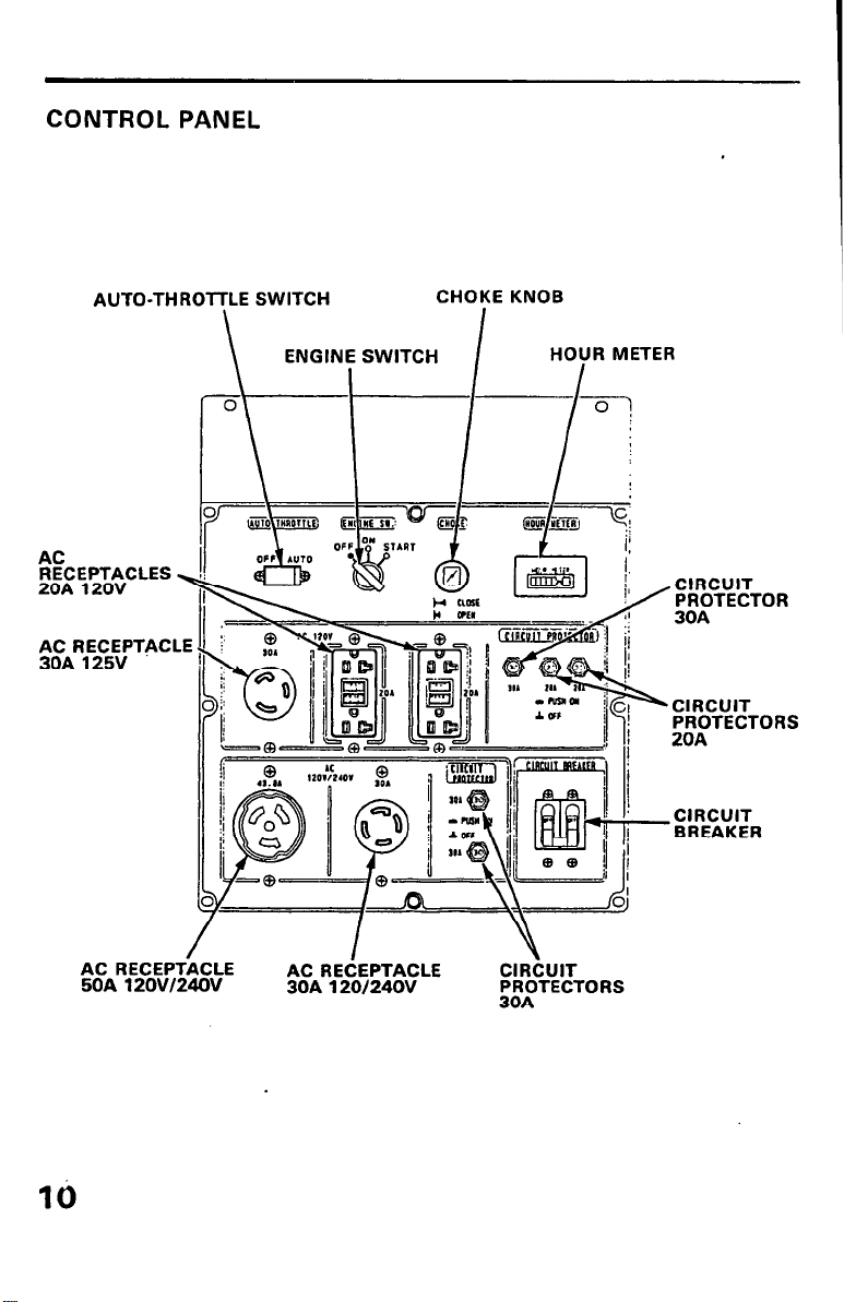
CONTROL PANEL
AUTO-THROTTLE SWITCH
AC
RECEPTACLES
20A 120V
FI~~R,E~~~~E~~TAC LE
ENGINE SWITCH
\
CHOKE KNOB
I I HoYR METER
l-L%ii%+ CIRCUIT
CTOR
BREAKER
AC RECEPTACLE
50A 12OVI24OV
/
I Y
AC RECEPTACLE CIRCUIT
30A 12Of 24OV PROTECTORS
30A
Page 13
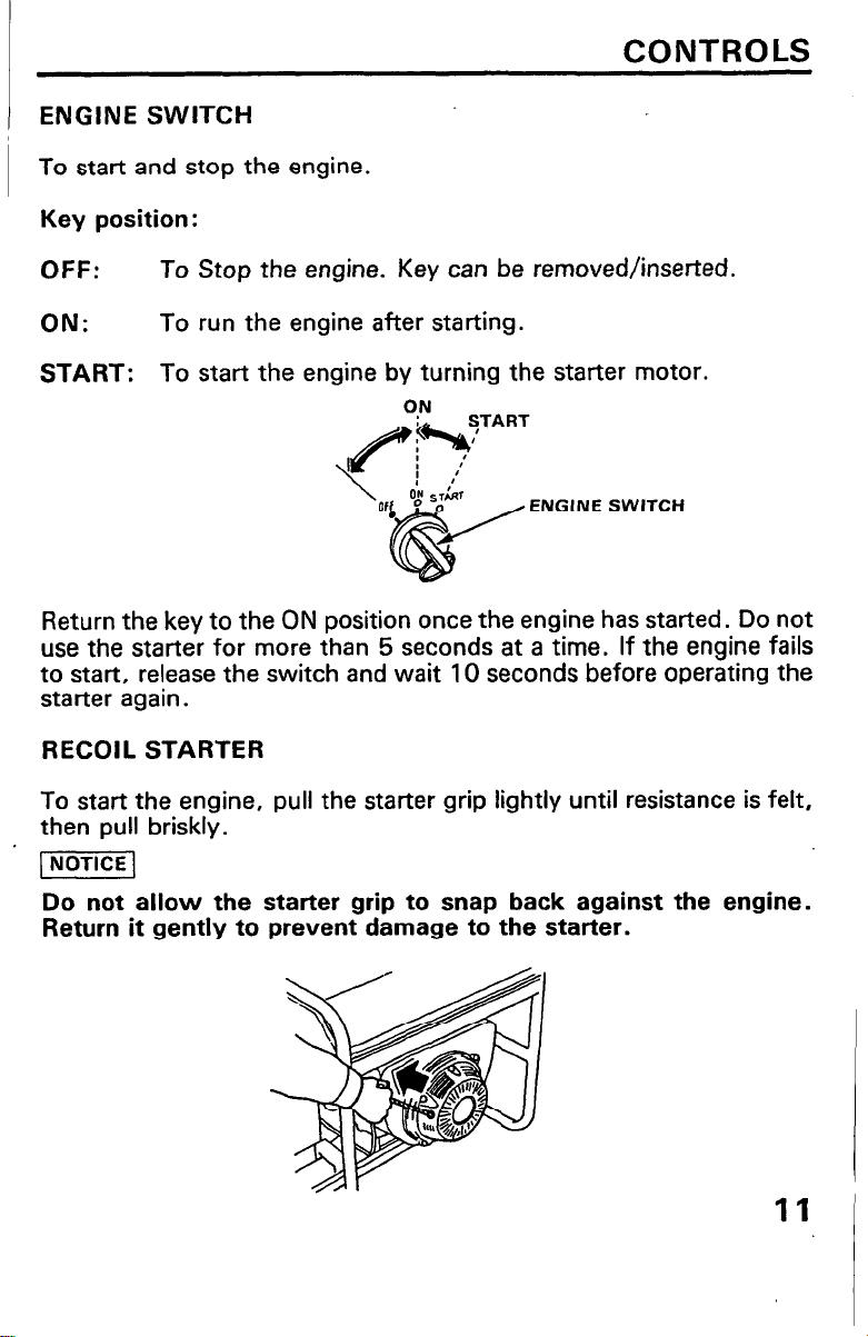
ENGINE SWITCH
To start and stop the engine.
Key position :
CONTROLS
OFF:
ON:
START: To start the engine by turning the starter motor.
Return the key to the ON position once the engine has started. Do not
use the starter for more than 5 seconds at a time. If the engine fails
to start, release the switch and wait 10 seconds before operating the
starter again.
RECOIL STARTER
To start the engine, pull the starter grip lightly until resistance is felt,
then pull briskly.
~NoTlCE1
Do not allow the starter grip to snap back against the engine.
Return it gently to prevent damage to the starter.
To Stop the engine. Key
To run the engine after starting.
OF ENGINE SWITCH
can
be removed/inserted.
11
Page 14
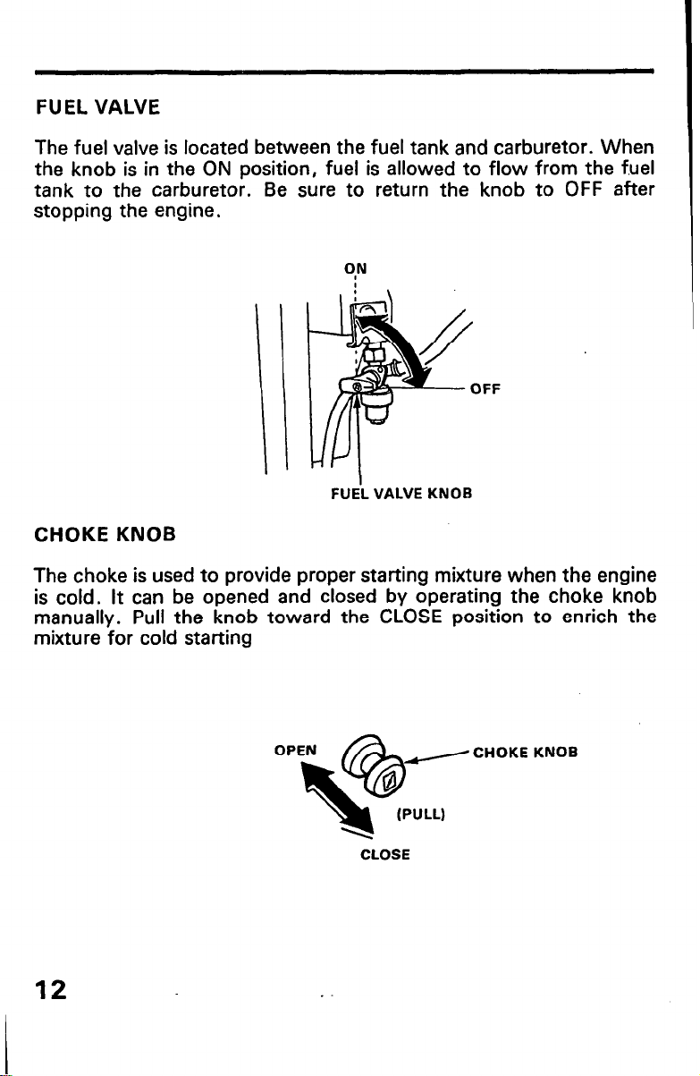
FUEL VALVE
The fuel valve is located between the fuel tank and carburetor. When
the knob is in the ON position, fuel is allowed to flow from the f.uel
tank to the carburetor. Be sure to return the knob to OFF after
stopping the engine.
FF
\
FUEi VALVE KNOB
CHOKE KNOB
The choke is used to provide proper starting mixture when the engine
is cold. It can be opened and closed by operating the choke knob
manually. Pull the knob toward the CLOSE position to enrich the
mixture for cold starting
12
KNOB
CLOSE
Page 15
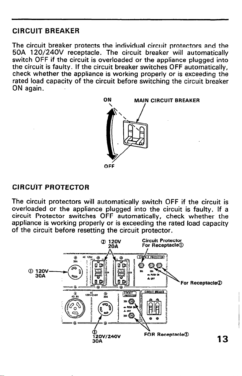
CIRCUIT BREAKER
The circuit breaker protects the individual circuit protectors and the
50A 120/24OV receptacle. The circuit breaker will automatically
switch OFF if the circuit is overloaded or the appliance plugged into
the circuit is faulty. If the circuit breaker switches OFF automatically,
check whether the appliance is working properly or is exceeding the
rated load capacity of the circuit before switching the circuit breaker
ON again.
ON
\
OFF
MA;N CIRCUIT BREAKER
CIRCU’IT PROTECTOR
The circuit protectors will automatically switch OFF if the circuit is
overloaded or the appliance plugged into the circuit is faulty. If a
circuit Protector switches OFF automatically, check whether the
appliance is working properly or is exceeding the rated load capacity
of the circuit before resetting the circuit protector.
Circuit Protector
For Receptacle@
I
12ov/24Ov
30A
For Receptacle@
FOR Receptacle@
13
Page 16
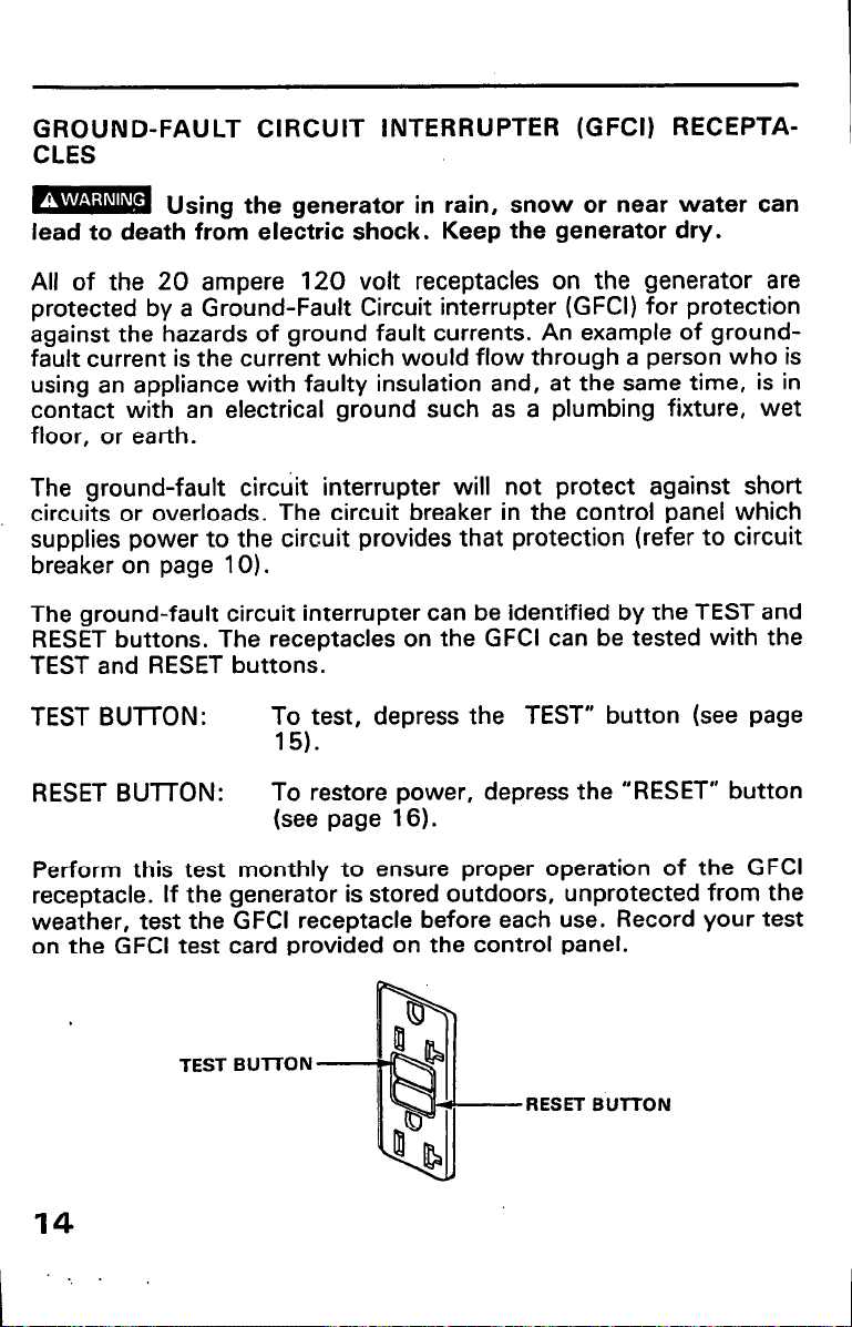
GROUND-FAULT CIRCUIT INTERRUPTER (GFCI) RECEPTACLES
BU sing the generator in rain, snow or near water can
lead to death from electric shock. Keep the generator dry.
All of the 20 ampere 120 volt receptacles on the generator are
protected by a Ground-Fault Circuit interrupter (GFCI) for protection
against the hazards of ground fault currents. An example of groundfault current is the current which would flow through a person who is
using an appliance with faulty insulation and, at the same time, is in
contact with an electrical ground such as a plumbing fixture, wet
floor, or earth.
The ground-fault circuit interrupter will not protect against short
circuits or overloads. The circuit breaker in the control panel which
supplies power to the circuit provides that protection (refer to circuit
breaker on page 10).
The ground-fault circuit interrupter can be identified by the TEST and
RESET buttons. The receptacles on the GFCI can be tested with the
TEST and RESET buttons.
TEST BUll-ON:
To test, depress the TEST” button (see page
15).
RESET BUTTON:
To restore power, depress the “RESET” button
(see page 16).
Perform this test monthly to ensure proper operation of the GFCI
receptacle. If the generator is stored outdoors, unprotected from the
weather, test the GFCI receptacle before each use. Record your test
on the GFCI test card provided on the control panel.
TEST Bull-ON
RESET BUlTON
14
Page 17
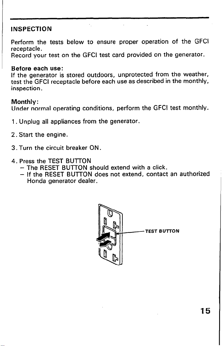
INSPECTION
Perform the tests below to ensure proper operation of the GFCI
receptacle.
Record your test on the GFCI test card provided on the generator.
Before each use:
If the generator is stored outdoors, unprotected from the weather,
test the GFCI receptacle before each use as described in the monthly,
inspection.
Monthly :
Under normal operating conditions, perform the GFCI test monthly.
1. Unplug all appliances from the generator.
2. Start the engine.
3. Turn the circuit breaker ON.
4. Press the TEST BUTTON
- The RESET BUTTON should extend with a click.
- If the RESET BUTTON does not extend, contact an authorized
Honda generator dealer.
-TEST BUTI-ON
15
Page 18
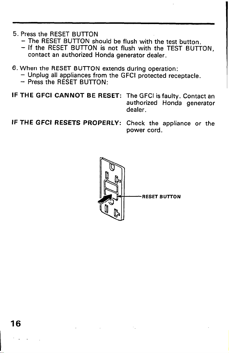
5. Press the RESET BUTTON
- The RESET BUTTON should be flush with the test button,
- If the RESET BUTTON is not flush with the TEST BUTTON,
contact an authorized Honda generator dealer.
6. When the RESET BUTTON extends during operation:
- Unplug all appliances from the GFCI protected receptacle.
- Press the RESET BUTTON:
IF THE GFCI CANNOT BE RESET: The GFCI is faulty. Contact an
authorized Honda generator
dealer.
IF THE GFCI RESETS PROPERLY: Check the appliance or the
power cord.
RESET BUT-I-ON
16
Page 19
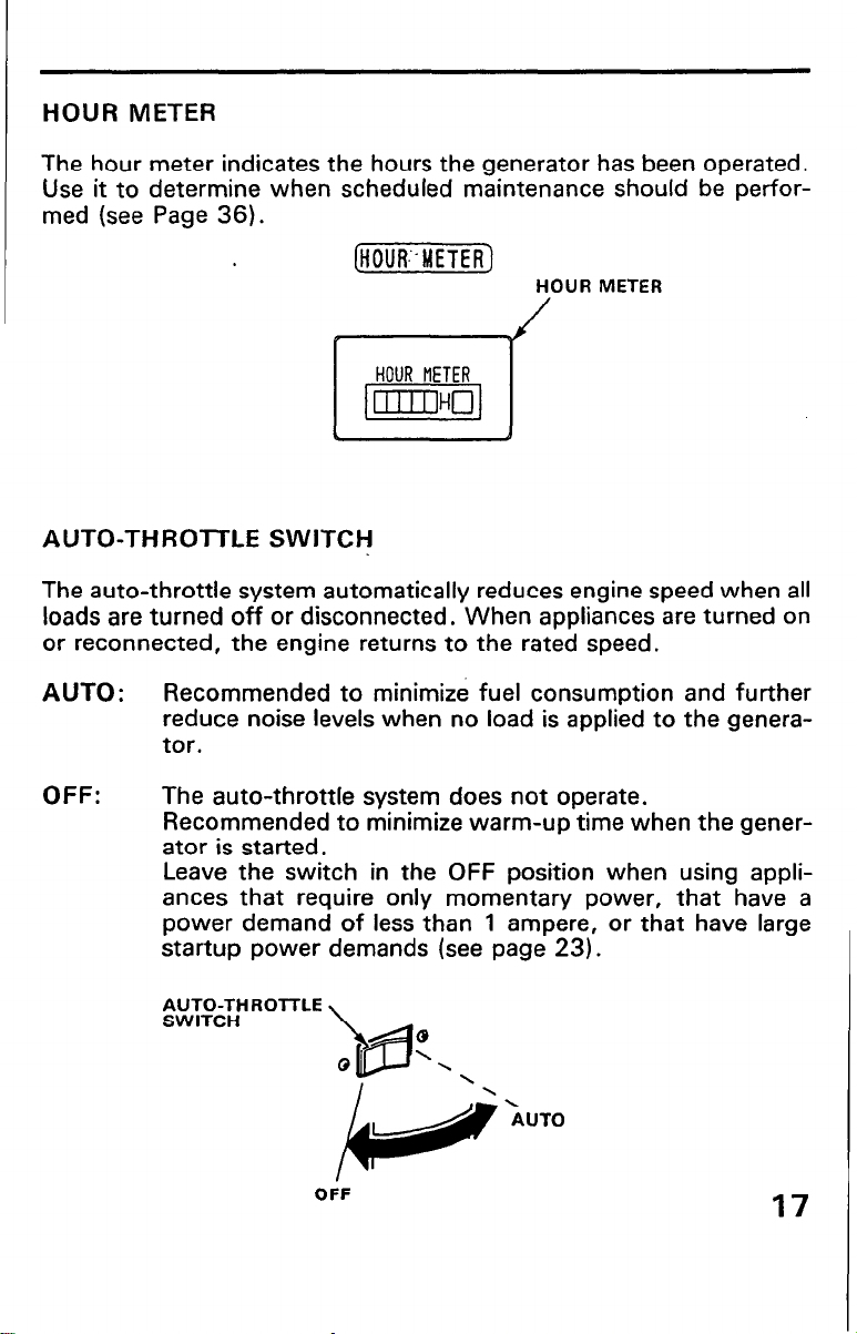
HOUR METER
The hour meter indicates the hours the generator has been operated.
Use it to determine when scheduled maintenance should be performed (see Page 36).
ljiummi]
HOUR METER
AUTO-THRO-lTLE SWITCH
The auto-throttle system automatically reduces engine speed when all
loads are turned off or disconnected. When appliances are turned on
or reconnected, the engine returns to the rated speed.
AUTO: Recommended to minimize fuel consumption and further
reduce noise levels when no load is applied to the genera-
tor.
OFF:
The auto-throttle system does not operate.
Recommended to minimize warm-up time when the generator is started.
Leave the switch in the OFF position when using appliances that require only momentary power, that have a
power demand of less than 1 ampere, or that have large
startup power demands (see page 23).
OiF
Page 20
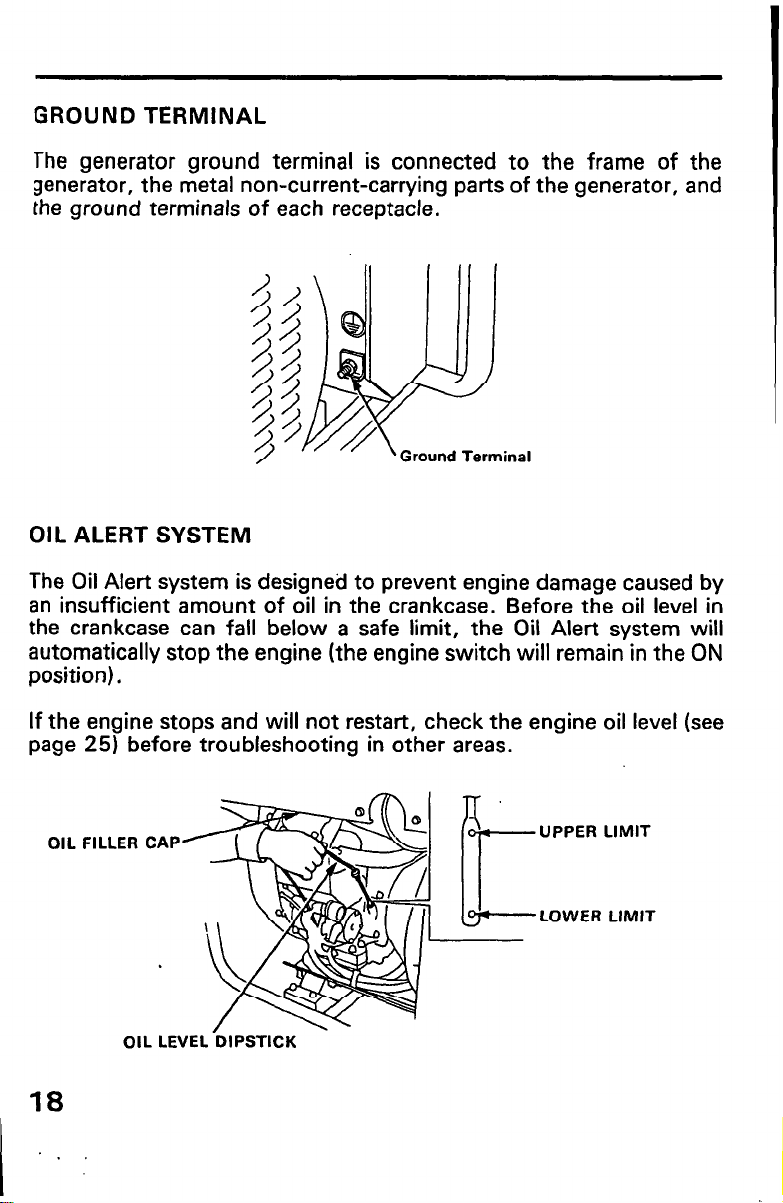
GROUND TERMINAL
The generator ground terminal is connected to the frame of the
generator, the metal non-current-carrying parts of the generator, and
the ground terminals of each receptacle.
Ground Terminal
OIL ALERT SYSTEM
The Oil Alert system is designed to prevent engine damage caused by
an insufficient amount of oil in the crankcase. Before the oil level in
the crankcase can fall below a safe limit, the Oil Alert system will
automatically stop the engine (the engine switch will remain in the ON
position).
If the engine stops and will not restart, check the engine oil level (see
page 25) before troubleshooting in other areas.
OIL FILLER CAP
OIL LEVEL DIPSTICK
UPPER LIMIT
LOWER LIMIT
18
Page 21
GENERATOR USE
CONNECTIONS TO A BUILDING’S ELECTRICAL SYSTEM
Connections for standby power to a building’s electrical system must
be made by a qualified electrician. The connection must isolate the
generator power from utility power, and must comply with all applicable laws and electrical codes.
Improper connections to a building’s electrical system can allow
electrical current from the generator to backfeed into the utility
lines. Such backfeed may electrocute utility company workers or
others who contact the lines during a power outage. Consult the
utility company or a qualified electrician.
Improper connections to a building’s electrical system can allow
electrical current from the utility company to backfeed into the
generator. When utility power is restored, the. generator may
explode, burn, or cause fires in the building’s electrical system.
GROUND SYSTEM
Honda portable generators have a system ground that connects
generator frame components to the ground terminals in the AC
output receptacles. The AC newtral wire is connected to the system
ground.
SPECIAL REQUIREMENTS
There may be Federal or State Occupational Safety and Health
Administration (OSHA) regulations, local codes, or ordinances that
apply to the intended use of the generator. Please consult a qualified
electrician, electrical inspector, or the local agency having jurisdiction.
l
In some areas, generators are required to be registered with local
utility companies.
l
If the generator is used at a construction site, there may be addi-
tional regulations which must be observed.
19
Page 22

AC APPLICATIONS
Before connecting an appliance or power cord to the generator:
l
Make sure that it is in good working order. Faulty appliances or
power cords can create a potential for electrical shock.
l
If an appliance begins to operate abnormally, becomes sluggish or
stops suddenly, turn it off immediately. Disconnect the appliance,
and determine whether the problem is the appliance, or if the rated
load capacity of the generator has been exceeded.
. Make sure that the electrical rating of the tool or appliance does not
exceed that of the generator. Never exceed the maximum power
rating of the generator, Power levels between rated and maximum
may be used for no more than 30 minutes.
NOTlCE]
Substantial overloading will open the circuit breaker. Exceeding
the time limit for maximum power operation or slightly overloading the generator may not switch the circuit breaker OFF, but will
shorten the service life of the generator.
Limit operation requiring maximum power to 30 minutes.
Maximum power is:
10.5 kVA
For continuous operation, do not exceed the rated power.
Rated power is:
9.5 kVA
In either case, the total power requirements (VA) of all appliances
connected must be considered. Appliance and power tool manufacturers usually list rating information near the model number or serial
number.
20
.
Page 23

AC OPERATION
1. Start the engine (see page 30).
2. Switch the AC circuit breaker ON.
3. Plug the appliance into the appropriate AC receptacle.
Do not exceed the current limit specified for any one receptacle. If an
overloaded circuit causes the AC circuit breaker or circuit protector to
switch OFF, reduce the electrical load on the circuit, wait a few
minutes and then reset the circuit breaker or circuit protector.
i !
%
%,
ON
@
@
t
CIRCUIT B’REAKER
21
Page 24

HOW TO USE THE RECEPTACLES
When. two or more receptacles are used, refer to the table below and
apply the load to each receptacle equally to prevent overloading.
Voltage fluctuation can be prevented by applying the load equally to
the single phase receptacles.
Receptacle
Case
Using 240 V only 39.6 A Max. 30 A Max.
Using 120 V only
Using both 120 V 1
and 240 V
240 ‘J 120v
50 A 30 A 50 A
39.6 A Total
50 A Max.
Total 10 A
Total 20 A
Total 30 A
30 A 20 A Max.
30 A Max.
Total 79.2 A
Total 59.2 A
Total 39.2 A
Total 19.2 A
20 A Max.
for both
at one
When both 240 V and 120 V receptacles are used, be sure that the
ampere draw at each receptacle is less than the specified capacity and
the total amperage is less than 79.2 A
22
12OVli4OV 5bA
12OVIi4OV 30A
Page 25

AUTO-THROll-LE SYSTEM
With the switch in the AUTO position, engine speed is automatically
reduced when ALL loads are turned OFF or disconnected. When
appliances are turned ON or reconnected, the engine returns to rated
speed. In the OFF position, the auto-throttle system does not oper-
ate.
The auto-throttle system will not respond to electrical loads of less
than 1 ampere. Turn the auto-throttle to the OFF position to operate
loads of less than 1 amp.
Appliances with large startup power demands
may not
allow the
engine to reach normal operating rpm when they are connected to the
generator. Turn the auto-throttle to the OFF position and connect the
appliance to the generator.
If the
engine
still will not reach normal
operating speed, check that the appliance does not exceed the rated
load capacity of the generator.
To avoid extended warm-up periods, keep the switch OFF until the
engine reaches operating temperature.
The auto-throttle system is not effective for use with appliances that
require only momentary power. If the tool or appliance will be turned
ON and OFF quickly, the auto-throttle switch should be in the OFF
position.
(AUTO. ,THRO&)
OFF AUTO
-i-
F
AUTO-THROTTLE SWITCH
(-1
23
Page 26

HIGH ALTITUDE OPERATION
At high altitude, the standard carburetor air-fuel mixture will be too
rich. Performance will decrease, and fuel consumption will increase.
A very rich mixture will also foul,the spark plug and cause hard
starting.
High altitude performance can be improved by specific modifications
to the carburetor. If you always operate your engine at altitudes
above 6,000 feet (1,800 meters) have your dealer perform this
carburetor modification.
Even with carburetor modification, engine horsepower will decrease
about 3.5% for each 1 ,OOO-foot (300-meter) increase in altitude.
The effect of altitude on horsepower will be greater than this if no
carburetor modification is made.
(1
When the carburetor has been modified for high altitude operation,
the air-fuel mixture will be too lean for low altitude use. Operation
at altitudes below 6,000 feet (1,800 meters) with a modified
carburetor may cause the engine to overheat and result in serious
engine damage. For use at low altitudes, have your dealer return
the carburetor to original factory specifications.
24
Page 27

PRE-OPERATION CHECK
ENGINE OIL
l
Engine oil is a major factor affecting engine performance and
service life. Nondetergent oils and 2-stroke engine oils are not
recommended because they have inadequate lubricating charac-
teristics.
l
Check the oil level BEFORE EACH USE with the engine on a
level surface and the engine stopped.
Use 4-stroke motor oil that meets or
exceeds the requirements for API service classification SF or SG. Always
check the API SERVICE label on the oil
container to be sure it includes the
letters SF or SG.
SAE low-30 is recommended for general use. Other viscosities
shown in the chart may be used when the average temperature in
your area is within the indicated range.
L I 1 1 1 1 I I
.30
-10 0 10 20 30 40x
-20
AMBIENT TEMPERATURE
Other viscosities shown in the chart may be used when the average
temperature in your area is within the indicated range.
1. Place the engine on a level surface.
2. Remove the dipstick and wipe it clean.
3. Fully insert the dipstick, then remove it to check the oil level.
If the oil level is near or below the lower limit mark on the dipstick,
4.
remove the oil filler cap, and fill with the recommended oil to the
upper limit mark.
Reinstall the dipstick and filler
5.
UPPER LIMIT
LOWER LIMI’
25
Page 28

FUEL
Refueling
Fuel tank capacity: 6.9 US gal (26e. 5.7lmp gal)
Check the fuel level gauge, and refill the tank if the fuel level is low.
Gasoline is highly flammable and explosive, and you can be
burned or seriously injured when handling fuel.
l
Stop engine and keep heat, sparks, and flame away.
l
Handle fuel only outdoors.
l
Wipe up spills immediately.
Refuel in a well-ventilated area before starting the engine. If the
engine has been running, allow it to cool. Refuel carefully to avoid
spilling. Do not fill above the shoulder of the fuel strainer. After
refueling, tighten the fuel tank cap securely.
Never refuel the generator inside a building where gasoline fumes may
reach flames or sparks. Keep gasoline away from appliance pilot
lights, barbecues, electric appliances, power tools, etc.
Spilled fuel is not only a fire hazard, it causes environmental damage.
Wipe up spills immediately.
LEVEL GAUGE
FUEL TA‘NK
CAP
Do not fill above fuel
strainer shoulder.
26
Page 29

Fuel Recommendations
Use unleaded gasoline with a pump octane rating of 86 or higher.
This engine is certified
Unleaded gasoline produces fewer engine and spark plug deposits
and extends exhaust system life.
Never use stale or contaminated gasoline or an oil/gasoline mixture.
Avoid getting dirt or water in the fuel tank.
Occasionally you may hearalight “spark knock” or “pinging” (metallic
rapping noise) while operating under heavy loads. This is no cause for
concern.
If spark knock or pinging occurs at a steady engine speed, under
normal load, change brands of gasoline. If spark knock or pinging
persists, see your servicing dealer.
1 NOTICE]
Running the engine with persistent spark knock or pinging can
cause engine damage.
Running the engine with persistent spark knock or pinging is misuse,
and the Distributor’s Limited Warranty does not cover parts dama,ged
by misuse.
to
operate on unleaded gasoline.
27
Page 30

Oxygenated Fuels
Some conventional gasolines are being blended with alcohol or an
ether compound. These gasolines are collectively referred to as
oxygenated fuels. To meet clean air standards, some areas of the
United States and Canada use oxygenated fuels to help reduce emissions.
If you use an oxygenated fuel, be sure it is unleaded and meets the
minimum octane rating requirement.
Before using an oxygenated fuel, try to confirm the fuel’s contents.
Some states/provinces require this information to be posted on the
pump.
The following are the EPA approved percentages of oxygenates:
ETHANOL- (ethyl or grain alcohol) 10% by volume
You may use gasoline containing up to 10% ethanol
by volume. Gasoline containing ethanol may be marketed under the name “Gasohol”.
MTBE-
METHANOL-(methyl or wood alcohol) 5% by volume
If you notice any undesirable operating symptoms, try another service
station or switch to another brand of gasoline.
Fuel system damage or performance problems resulting from the use
of an oxygenated fuel containing more than the percentages of
oxygenates mentioned above are not covered under warranty.
(methyl tertiary butyl ether) 15% by volume
You may use gasoline containing up to 15% MTBE by
volume.
You may use gasoline containing up to 5% methanol
by volume as long as it also contains cosolvents and
corrosion inhibitors to protect the fuel system. Gasoline containing more than 5% methanol by volume
may cause starting and/or performance problems. It
may also damage metal, rubber, and plastic parts of
your fuel system.
28
Page 31

AIR CLEANER
1. Remove the wing bolt and air cleaner cover and remove the foam
air filter.
2. Inspect the air filters. Clean or replace the filters if necessary. If the
air filters need cleaning, follow the procedure described on page
39.
3. Reinstall the air filters and air cleaner cover. Tighten the wing bolt
securely.
PAPER AIR FILTER
AIR CLEANER COVER
r-l\ T
CLEAN CHAMBER
I
AIR CLEANER BODY
Do not allow dust, dirt, and debris to enter the air cleaner body
when servicing the air cleaner.
29
Page 32

STARTING THE ENGINE
STARTING THE ENGINE
1. Turn the fuel valve ON
2. Make sure that the circuit breaker is OFF.
The generator may be hard to start if a load is connected.
3. Make sure the auto-throttle switch is off, or more time will be
required for warm up.
4. Turn the engine switch to START and hold it there until the engine
starts.
Do not use the electric starter for more than 5 seconds at a time.
If the engine fails to start, release the switch and wait 10 seconds
before operating the starter again.
Pull the choke knob out to the CLOSE position to start a cold
engine. The choke may not be needed if the engine is warm or the
air temperature is hot.
CHOKE KNOB
CLOSE
When the speed of the starter motor drops after a period of
time, it is an indication that the battery should be recharged.
5. After the engine starts, let the engine switch return to ON.
6. Warm up the engine for 2-3 minutes.Turn the auto-throttle switch
to AUTO after the engine has warmed up.
30
Page 33

STOPPING THE ENGINE
STOPPING THE ENGINE
In an emergency:
1. To stop the engine in an emergency, move the engine switch to the
OFF position.
In normal use:
1. Turn the AC circuit breaker to the OFF position.
2. Move the engine switch to the OFF position.
3. Turn the fuel valve to the OFF position.
31
Page 34

MAINTENANCE
THE IMPORTANCE OF MAINTENANCE
Good maintenance is essential for safe, economical, and trouble-free
operation. It will also help reduce air pollution.
To help you properly care for your generator, the following pages
include a maintenance schedule, routine inspection procedures, and
simple maintenance procedures using basic hand tools. Other service
tasks that are more difficult, or require special tools, are best handled
.by professionals and are normally performed by a Honda technician or
other qualified mechanic.
The maintenance schedule applies to nomal operating conditions. If
you operate your generator under unusual conditions, consult your
servicing dealer for recommendations applicable to your individual
needs and use.
Improper maintenance, or failure to correct a problem before
operation, can cause a malfunction in which you can be seriously
hurt or killed.
Always follow the inspection and maintenance recommendations
and schedules in this owner’s manual.
32
Page 35

MAINTENANCE SAFETY
Some of the most important safety precautions follow. However, we
cannot warn you of every conceivable hazard that can srise in petfor-
ming maintenance. Only you can decide whether or not you should
perform a given task.
Failure to properly follow maintenance instructions and precau-
tions can cause you to be seriously hurt or killed.
Always follow the procedures and precautions in the owner’s
manual.
Safety Precautions
. Make sure the engine is off before you begin any maintenance or
repairs. This will eliminate several potential hazards:
-Carbon monoxide poisoning from englne exhaust.
Be sure there is sdequate ventilation whenever you operate the
engine.
-Bums from hot parts.
Let the engine and exhaust system cool before touching.
-Injury from moving parts.
Do not run the engine unless instructed to do so.
l
Read the instructions before you begin, and make sure you have the
tools and skills required.
l
To reduce the possibility of fire or explosion, be careful when
working around gasoline. Use only a nonflammable solvent, not
gasoline, to clean parts. Keep cigarettes, sparks, and flames away
from all fuel-related parts.
Remember that your servicing dealer knows your generator best and
is fully equipped to maintain and repair it.
To ensure the best quality and reliability, use only new, genuine
Honda parts or their equivalents for repair and replacement.
33
Page 36

EMISSION CONTROL SYSTEM
Source of Emissions
The combustion process produces carbon monoxide, oxides of nitro-
gen, and hydrocarbons. Control of hydrocarbons and oxides of
nitrogen is very important because, under certain conditions, they
react to form photochemical smog when subjected to sunlight.
Carbon monoxide does not react in the same way, but it is toxic.
Honda utilizes lean carburetor settings and other systems to reduce
the emissions of carbon monoxide, oxides of nitrogen, and hydrocar-
bons.
The California Clean Air Act
California regulations require all manufacturers to furnish written
instructions describing the operation and maintenance of emission
control systems.
The following instructions and procedures must be followed in order
to keep the emissions from your Honda engine within the emission
standards.
Tampering and Altering
Tampering with or altering the emission control system may increase
emissions beyond the legal limit. Among those acts that constitute
tampering are:
l
Removal or alteration of any part of the intake, fuel, or exhaust
systems.
l
Altering or defeating the governor linkage or speed-adjusting mech-
anism to cause the engine to operate outside its design parameters.
34
Page 37

Problems That May Afect Emissions
If you are aware of any of the following symptoms, have your engine
inspected and repaired by your servicing dealer.
* Hard starting or stalling after starting.
l
Rough idle.
l
Misfiring or backfining under load.
l
Afterburning (backfiring).
l
Black exhaust smoke or high fuel consumption.
PROPER MAINTENANCE IS THE OWNER’S RESPONSIBILITY
Replacement Parts
The emission control systems on your Honda engine were designed,
built, and certified to conform with California emissions regulations.
Honda recommends only the use of new, genuine Honda parts or
their equivalent.
The use of other replacement parts which are not of equivalent quality
may impair the effectiveness of your emission control system.
Maintenance
Follow the maintenance schedule on page 36. Remember that this
schedule is based on the assumption that your machine will be used
for its designed purpose. Sustained high-load or high-temperature
operation, or use in unusually wet or dusty conditions, will require
more frequent service.
35
Page 38

MAINTENANCE SCHEDULE
REGULAR SERVICE PERIOD(B) 1
ITEM Perform at every indicated
month or operating hour interval. whichever comes
l
Emission related items.
l
Replace the paper air fllter only.
First
1 Every ( Every
(1)Service more frequently when used in dusty aress.
Every
(2)These items should be serviced by an authorized Honda engine
dealer, unless the owner has the proper tools and is mechanically
proficient. See the Honda Shop Manual.
(3)For commercial use, log hours of operation to determine proper
maintenance intervals.
36
.
Page 39

ENGINE OIL CHANGE
Drain the oil while the engine is warm to assure rapid and complete
draining.
1. Remove the oil filler cap and drain bolt, and drain the oil into a
e
suitable container.
2. Retighten the drain bolt securely.
3
3. Refill to the upper limit mark on the dipstick with the recommended
oil (see page 25). Tighten the oil filler cap securely.
ENGINE OIL REFILL CAPACITIES:
Without oil filter replacement:
1.27 US qt (1.20 et 1.06 Imp qt)
With oil filter replacement:
1.59USqt(1.50e, 1.32Impqt)
ENGINE-OIL DIPSTICK
OIL FIL/LER CAP
Wash your hands with soap
OIL DdlN
and
water after handling used oil.
BOLT
Please dispose of used motor oil in a manner that is compatible with
the environment. We suggest you take it in a sealed container to your
local service station or recycling center for reclamation. Do not throw
it in the trash, pour it on the ground or down a drain.
37
Page 40

OIL FILTER CHANGE
1. Drain the engine oil, and retighten the drain bolt securely (see page
37).
2. Remove the oil filter, and drain the oil into a suitable container.
Discard the used oil filter.
piEi%-)
Use an oil filter socket tool, rather than a strap wrench, to avoid
striking
3. Clean the filter nounting base, and coat the O-ring of the new oil
filter with clean engine oil.
[NOTICE]
Use only a Honda genuine oil filter or a filter of equivalent
quality specified for your model. Using the wrong Honda filter
or a non-Honda filter which is not of equivalent quality may
cause engine damage.
4. Screw on the new oil filter by hand, until the O-ring contacts the
filter mounting base, then use an oil filter socket tool to tighten the
filter an additional 7/8 turn.
TORQUE: 16 ft-lb (22 Nm, 2.2 kg-m)
5. Refill the crankcase with the specified amount of the recommended
oil (see page 25 & 33). Reinstall the oil filler cap/dipstick.
6. Start the engine and check for oil filter leaks.
7. Stop the engine, and check the oil level as described on page 25.
If necessary, add oil to the upper limit mark on the’dipstick.
O-RING
38
ILTER SOCKET TOOL
Page 41

AIR CLEANER SERVICE
Dirty air filters will restrict air flow to the carburetor, reducing engine
performance. If you operate the generator in very dusty areas, clean
the air filters more often than specified in the MAINTENANCE
SCHEDULE.
pi%iEq
Operating the engine without air filters, or with damaged filters,
will allow dirt to enter the engine, causing rapid engine wear. This
type of damage is not covered by the Distrlbutor’s Limited Warranty.
1. Remove the wing bolt, and remove the air cleaner cover.
2. Remove the two 5 mm screws from the air cleaner cover, and
remove the paper air filter from the cover.
3. Remove the foam air filter from the air cleaner body.
4. Inspect both air filters, and replace them if they are damaged. Also,
replace the paper air fitter every year, or 300 hours of
whichever occurs first.
5. Clean the air filters if they are to be reused.
use,
Paper air filter. Tap the filter several times on a hard surface to remove
dirt, or blow compressed air [not exceeding 30 psi (207 kPa, 2.1 kg/
cm2)] through the filter from the clean side. Never try to brush off
dirt; brushing will force dirt into the fibers.
Foam air filter. Clean in warm soapy water, ninse, and allow to dry
thoroughly. Or clean in nonflammable solvent and allow to dry. Dip
the filter in clean engine oil, then squeeze out all excess oil. The
engine will smoke when started if too much oil is left in the filter.
39
Page 42

6. Wipe dirt from the inside of the air cleaner body and cover, using
a moist rag. Be careful to prevent dirt from entening the air duct
that leads to the carburetor.
7. Reinstall the air filters and cover. Be sure that both gaskets are
installed on the paper air filter. Tighten the wing bolt securely.
AIR CLEANER COVER
PAPER ELEMENT
GASKET
FOAM ELEMENT
CLEAN CHAMBER
5 mm SCREWS
AIR CLEANER BODY
40
.
Page 43

SPARK PLUG SERVICE
Recommended spark plugs:
BPRGES (NGK)
WZOEPR-U (NIPPONDENSO)
To ensure proper engine operation, the spark plugs must be properly
gapped and free of deposits.
%
If the engine has been running, the exhaust pipe and muffler will be
very hot. Be careful to avoid touching the exhaust pipe or muffler.
Remove the spark plug caps.
1.
2.
Clean any dirt from around the spark plug bases.
3.
Use a plug wrench to remove the spark plugs.
PLUG WRENCH
I
4.
Visually inspect the spark plugs. Discard them if the insulator is
cracked or chipped. Clean the spark plugs with a wire brush if they
are to be reused.
5.
Measure the spark plug electrode gap with a suitable gauge. The
gap should be 0.028-0.031 in (0.70-0.80 mm). Correct the gap,
if necessary, by carefully bending the side electrode.
0.028-0.031 in
(0.70-0.80 mm)
41
Page 44

6. Check that the spark plug washer is in good condition and thread
the spark plug in by hand to prevent cross-threading.
7. After the spark plug is seated, tighten with a spark plug wrench to
compress the washer.
-
If installing a new spark plug, tighten l/2 turn after the spark
plug seats to compress the washer.
- If reinstalling a used spark plug, tighten l/8 - l/4 turn after the
spark plug seats to compress the washer.
pEiGNOTICE]
l
The spark plug must be securely tightened. An improperly
tightened spark plug can become very hot and may cause
engine damage.
l
Use only the recommended spark plug or equivalent. A spark
plug which has an improper heat range may cause engine
damage.
42
. .
Page 45

SPARK ARRESTER MAINTENANCE
The spark arrester must be serviced every 100 hours to keep it
functioning as designed.
If the engine has been running, the exhaust pipe and muffler will be
very hot. Allow the exhaust pipe and muffer to cool before Servicing
the spark arrester.
1 , Remove the special screw from the muffler and remove the spark
arrester.
SPARK ARRESTER
43
Page 46

!. Use a brush to clean carbon deposits from the spark arrester
screen.
3. The spark arrester must be free of breaks and holes. Replace, if
necessary.
4. Install the spark arrester and the muffler in the reverse order of
disassembly.
44
Page 47

FUEL SEDIMENT CUP CLEANING
The sediment cup prevents dirt or water which may be in the fuel tank
from entering the carburetor. If the engine has not been run for a long
time, the sediment cup should be cleaned.
1. Turn the fuel valve OFF. Remove the sediment cup.
2. Clean the cup thoroughly.
3. Reassemble. Do not damage the O-ring.
FUEL VALVE
SEDIMENT CUP
45
Page 48

FUEL FILTER
1. Remove the two 6 mm special bolts from the control cover and
remove the control cover.
6 mm SPECIAL BOLT
2. Check the fuel filter for water accumulation or sediment. If no
water or sediment is found, reinstall the control cover.
FUEL FILTER
(i
3. If the fuel filter is found with excessive water accumulation or
sediment, take the generator to your servicing dealer.
46
Page 49

FUSE REPLACEMENT
If the fuse is blown, the engine will not start until it is replaced.
1. Turn the engine switch OFF.
2. Remove the fuse holder and replace the fuse. Use only a 1 OA fuse.
I
l
If frequent fuse failure occurs, determine the cause and
correct the problem before attempting to operate the generator further.
l
Never use a fuse with a rating other than 10 A. Serious
damage to the electrical system or a fire may result.
FUSEHOLDER
47
Page 50

BATTERY
‘_
The generator’s engine has a 3-amp charging system to charge the
battery while the engine is running. If the generator is only used
periodically, the battery must be charged monthly to maintain the
battery service life.
A
lead
acid battery self discharges at a rate of 0.5- 1 .O% per day.
This means that the battery, if the generator is not operated in a
month, can discharge as much as 30% in the same period. This could
cause the engine not to crank or shorten the service life of the battery.
To charge the battery, follow the procedures below.
Removal :
1. Remove the battery set plate.
2. Remove the negative (-) cable from the battery negative (-)
terminal; then remove the positive (+) cable from the battery
positive (+) terminal.
NEGAl
‘IVE(-j
CABLE
.
/
BATTERY
SET PLATE
3. Remove the battery from the battery tray.
48
Page 51

Inspection :
1. Remove the battery cell caps.
2. Inspect the electrolyte level of
each cell. The electrolyte level
must be maintained between the
UPPER and LOWER limit marks.
3. If the electrolyte level is near the
LOWER mark, add distilled
water as necessary.
UPPER LIMIT
LOWER LIMIT
The battery contains sulfuric acid (electrolyte) which is highly
corrosive and poisonous.
Getting electrolyte in your eyes or on your skin can cause serious
bums.
Wear protective clothing and eye protection when working near
the battery.
EMERGENCY PROCEDURES:
Eyes- Flush with water from a cup or other container for at least 15
minutes (water under pressure can damage the eye), Immediately call
a physician, local poison control, or 91 1.
Skin- Remove contaminated clothing. Flush the skin with large
quantities of water. Call a physician immediately.
Swallowing - Drink water or milk. Call your local poison control center
or a physician immediately.
49
Page 52

Charging:
The battery is rated at 14AH (ampere-hour). 10% of the ampere-
hour rating should be used as the charging current. A battery charger
should be used that can be adjusted to deliver 1.4 amps.
The battery gives off expiosive hydrogen gas during normal opera-
tion.
A spark or open flame can cause the battery to explode with
enough force to kill or seriously hurt you.
Keep sparks and flames away. Wear protective clothing and a
face shield, or have a skilled mechanic do battery maintenance.
1. Remove the battery cell caps.
2. Connect the battery charger following the manufacturer’s instructions.
3. Charge the battery 3-4 hours.
4. After the battery is charged, inspect the electrolyte level in each of
the cells. Add distilled water as necessary.
5. Install the battery caps.
6. Clean the outside of the battery and the battery tray with a solution
of baking soda and water.
Installation:
1. Install the battery in the generator.
2. Install the positive (+) cable to the battery positive (+) terminal;
then install the negative (-) cable to the battery negative (-)
terminal.
3. Install the battery set plate.
50
‘,
Page 53

TRANSPORTING/STORAGE
When transporting the generator, turn the engine switch and the fuel
valve OFF. Keep the generator level to preventfuel spillage. Fuel
vapor or spilled fuel may ignite.
If the engine has been running, allow it to cool for at least 15 minutes
before loading the generator on the transport vehicle or placing it in
storage. A hot engine and exhaust system can bum you and can ignite
some materials.
Take care not to drop or strike the generator when transporting. Do
not place heavy objects on the generator.
Before storing the unit for an extended period:
1. Be sure the storage area is free of excessive humidity and dust.
2. Service according to the table below:
STORAGE TIME
Less than 1 month
1 to 2 months
2 months to 1 year
1 year or more
* Use gasoline conditioners that are formulated to extend storage life.
Contact your authorized Honda generator dealer for conditioner recommendations.
RECOMMENDED SERVICE PROCEDURE TO
PREVENT HARD STARTING
No preparation required
Fill with fresh gasoline and add gasoline
conditioner*.
Fill with fresh gasoline and add’ gasoline
conditioner*.
Drain the carburetor float bowl (page 52).
Drain the fuel sediment cup (page 45).
Fill with fresh gasoline and add gasoline
conditioner*.
Drain the carburetor float bowl (page 52).
Drain the fuel sediment cup (page 45).
Remove the spark plugs. Pour a tablespoon (5 - 10
cc) of clean engine oil into each cylinder. Using the
electric starter, crank the engine a few revolutions to
distribute the oil in the cylinders. Reinstall the spark
plugs.
Change the engine oil (page 37).
After removal from storage, drain the stored gaso-
line into a suitable container, and fill with fresh
1 gasoline before starting.
51
Page 54

Before storing the unit for an extended period;
1. Be sure the storage area is free of excessive humidity and dust.
2. Drain the fuel.
a. Disconnect the fuel line to the engine, and drain the fuel tank
into an approved gasoline container. Turn the fuel valve to the
ON position to enable draining. After draining is completed,
reconnect the fuel line.
b. Remove the control cover (see page 46), loosen the carburetor
drain screw, and drain the carburetor into an approved gasoline
container. After draining is completed, tighten the carburetor
drain screw, and reinstall the control cover.
Gasoline is highly flammable and explosive, and you can be
burned or seriously injured when handling fuel.
l
Stop engine and keep heat, sparks, and flame away.
l
Handle fuel only outdoors.
l
Wipe up spills immediately.
52
. .
CARBURETOR
DRAIN
SCREW
Page 55

3. Change the engine oil (page 37).
4. Remove the two spark plugs and pour
engine oil into the cylinders. Crank the engine several revolutions
to distribute the oil, then reinstall the spark plugs.
5. Remove the battery and store it in a cool, dry place. Recharge it
once a month.
6. Cover the engine to keep out dust.
about
a tablespoon of clean
53
Page 56

I
TROUBLESHOOTING
When the engine will not start:
- NO
Is there fuel in the
tank 1
YES
Refill the fuel tank.
Is there enough oil NO
in the engine ?
YES
Is there a spark NO Replace the
from the spark
plugs ?
B
Be sure there is no
spilled fuel around the
spark plugs. Spilled
fuel may ignite.
YES
”
Is the fuel reaching NO
the carburetor 7
spark plugs.
To check:
1) Remove one spark
plug cap and clean
any dirt from around
the spark plug.
2) Remove the spark
plug and install the
T;;kcakJg in the
3) Set the * plug side
electrode on the cylinder head.
4) Crank the engine,
sparks should jump
across the gap.
Add the recom-
mended oil.
Still NO spark
Take the generator
to an authorized
Honda generator
dealer.
Clean the fuel sediment cup.
YES
If the engine still
does not start, take
the generator to an
authorized Honda
generator dealer.
54
To check:
from the drain when
the engine switch is
turned on.
DRAIN SCREW
Page 57

No electricity at the AC receptacles:
Is the circuit breaker ON ?
Is the circuit protector reset 7
Is the GFCI receptacle reset 7
YES
Check the electrical appliante or equipment for any
defects.
DEFECTS
NO
Turn the circuit breaker
l ON.
Reset the circuit protector.
Reset the GFCI receptacle.
NO DEFECTS
Take the generator to an
’ authorized Honda genera-
tor dealer.
l
l
Replace the electrical
appliance or equipment.
l
Take the electrical appliance or equipment to an
electrical repair shop.
I
55
Page 58

WIRING DIAGRAM
::
m
I
1
8
,
#
i
I
I
0
I
0
I
!
0
1
!
0
i
I
i
,
;
!
i
i
j
.j
ii
I
:I
;!
i
I
i
;i
!I
::
i/
.I
:I
56
Page 59

DIMENSIONS
Model
Length
Width
Height
Dry weight
ENGINE
Model
Engine Type
Displacement
[Bore x Stroke]
Engine Speed
Cooling System
Ignition System
Engine Oil Refill Capacities
Fuel Tank Capacity
Spark Plugs
GENERATOR
Model
Tvpe
Rated voltage
Rated freauencv 1 60 Hz
AC output
Rated ampere ’ 1 79.2/39.(
Rated outout j 9.5 kVA
Maximum’output 1 10.5 kVA
SPECIFICATIONS
E811000
37.5 in (953 mm)
24.3 in (617 mm)
24.5 in (622 mm)
403 lb (183 kg)
GX620
4-Stroke, O.H.V. 2 cylinder
37.5 cu in (614 cm51
3.03 x 2.60 in (77 x 66 mm)
3600rpm
Forced air
Transistorzed magneto
1.27 US qt (1.20e, 1.06 Imp qt)
without oil filter replacement
1.59 USqt (1.50e, 1.32 Impqt)
with oil filter replacement
6.9 US gal (26 e, 5.7 Imp gal)
BPRGES (NGK)
j E811000
I 2-Dole. re
( liO/240
6A
TUNEUP
I
Spark plug gap
Valve clearance
- Other specifications
ITEM
I
1 0.028-0.031 in (0.70-0.80 mm)
SPECIFICATION’
Refer to page: 36
IN: 0.15 2
EX: 0.20 & 0.02 mm (cold) 1 Honda dealer
0.02 mm (cold)
No other adjustments needed.
See your authorized
Specifications are subject to change without notice.
MAINTENANCE
I
57
Page 60

WARRANTY SERVICE INFORMATION
Honda power equipment dealership personnel are trained professionals. They should be able to answer any question you may have. If
you encounter a problem that your dealer does not solve to your
satisfaction, please discuss it with the dealership’s management. The
Service Manager or General Manager can help. Almost all problems
are solved in this way.
If you are dissatisfied with the decision made by the dealership’s
management, contact the Honda Power Equipment Customer Service
Office. You can write to:
American Honda Motor Co., Inc.
Honda Power Equipment Division
Customer Relations Office
4475 River Green Parkway
Duluth, Georgia 30136-2565
Or telephone: (770) 497-6400
When you write or call, please give us this information:
l
Model and serial number (see page 9)
l
Name of dealer who sold the generator to you
l
Name and address of dealer who services your generator
l
Date of purchase
l
Your name, address, and telephone number
l
A detailed description of the problem
58
Page 61

59
Page 62

INDEX
COMPONENT IDENTIFICATION
CONTETS
CONTROLS
Auto-throttle Switch ..............................................................
Choke KnoB
Circuit Breaker ........................................................................
Circuit protector
Engine Switch
Fuel Valve
Ground Fault Circuit Interrupter (GFCI) Receptacle
Ground
Hour Meter ..............................................................................
Oil Alert System
Recoil Starter ...........................................................................
GENERATOR USE
AC Applications
AC Operation
Auto-throttle System
Connections to a Building’s Electrical System
Ground
High Altitude Operation
How
Special Requirements
INDEX
MAINTENANCE
Air Cleaner Service
Battery
Emission Control System
Engine Oil Change
Fuel Filter
Fuel Sediment Cup Cleaning
Fuse Replacement
Importance of
Maintenance Safety
Maintenance Schedule
....................................................................................
..............................................................................
...........................................................................
.....................................................................
........ . ................................................................
..............................................................................
Terminal ....................................................................
.....................................................................
.....................................................................
.....................................................................
...........................................................................
..............
System..
to Use the
.......................................................................................
....................................................................................
.....................................................................
Recep tacles..
...............................................................
.......................................................................
..................................................................
..................................................................
..............................................................................
..................................................................
Maintenance
...............................................................
............................................................
...................................................
..................
. ................................................
...........................
.........................................................
................................................
.........................................................
...................................................
......................................................
3”
11
.17
12
13
13
11
12
14
.18
1’8
11
::
;;
19
.19
24
.22
ii:
.32
ii
i;
46
t;
32
33
36
60
Page 63

Oil Filter Change
.....................................................................
Proper Maintenance is the Owner’s Responsibility
Spark Arrester Maintenance
Spark Plug Service
..................................................................
PRE-OPERATION CHECK
Air Cleaner
Engine Oil
.......................................................................................
Fuel
SAFETY
..............................................................................
..............................................................................
.......................................................................................
Safety Label Locations
Safety Information
SPECIFICATIONS
..................................................................
.....................................................................
STARTING THE ENGINE
STOPPING THE ENGINE
TRANSPORTING AND STORAGE
TROUBLESHOOTING
..................................................................
WARRANTY SERVICE INFORMATION
WIRING DIAGRAM ..................
...................................................
.........................................................
............................................................
............................................................
............................................................
................................................
....................................... zi
. ..................................................
.................. zt
t::
25
27
25
26
4
4
6
3”:
31
51
56
61
Page 64

Page 65

Page 66

Page 67

Page 68

31YZA600
00X31-YZA-6000
Printed on
Recycled Paper
POM52329-CVR
Kinkos
160.2002.07
PRINTED IN U.S.A.
 Loading...