

Page 1
INSTALLATION
www.collegehillshonda.com
INSTRUCTIONS
Accessory Application
BACK-UP SENSOR
2008 ACCORD
2-DOOR
Publications No.
AII 37561-38377
Issue Date
NOV 2007
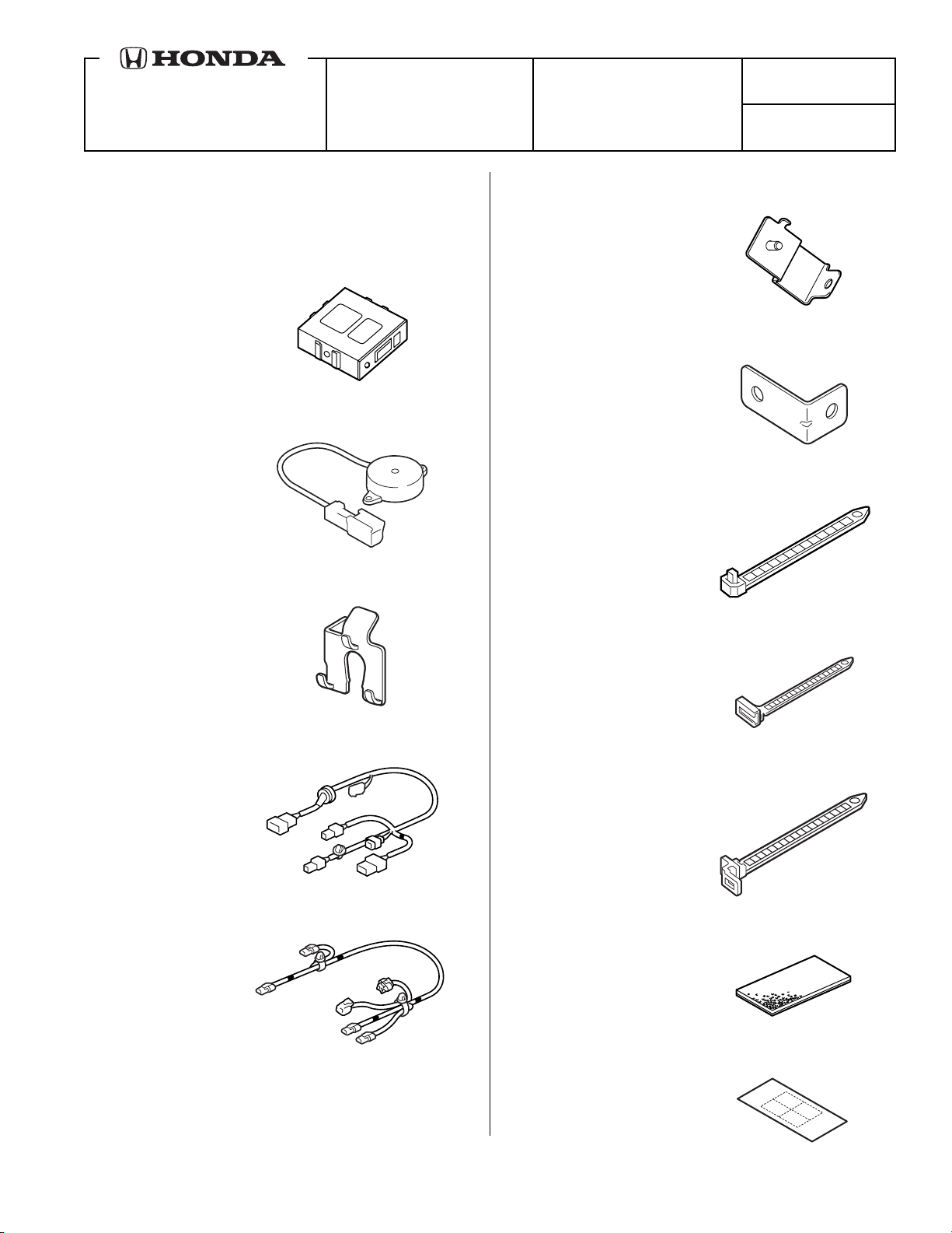
PARTS LIST
Back-up Sensor Attachment Kit
P/N 08V67-TE0-100A
Control unit
Beeper
4 Sensor clips
Control unit bracket (L4)
Control unit bracket (V6)
13 Wire ties
Wire tie with clip
Back-up sensor harness
2 Wire ties with holder
Back-up sensor subharness
2 Urethane tapes
Fuse label
© 2007 American Honda Motor Co., Inc. – All Rights Reserved. AII 37561-38377 (0711) 1 of 15
08V67-TE0-1000-91
Page 2
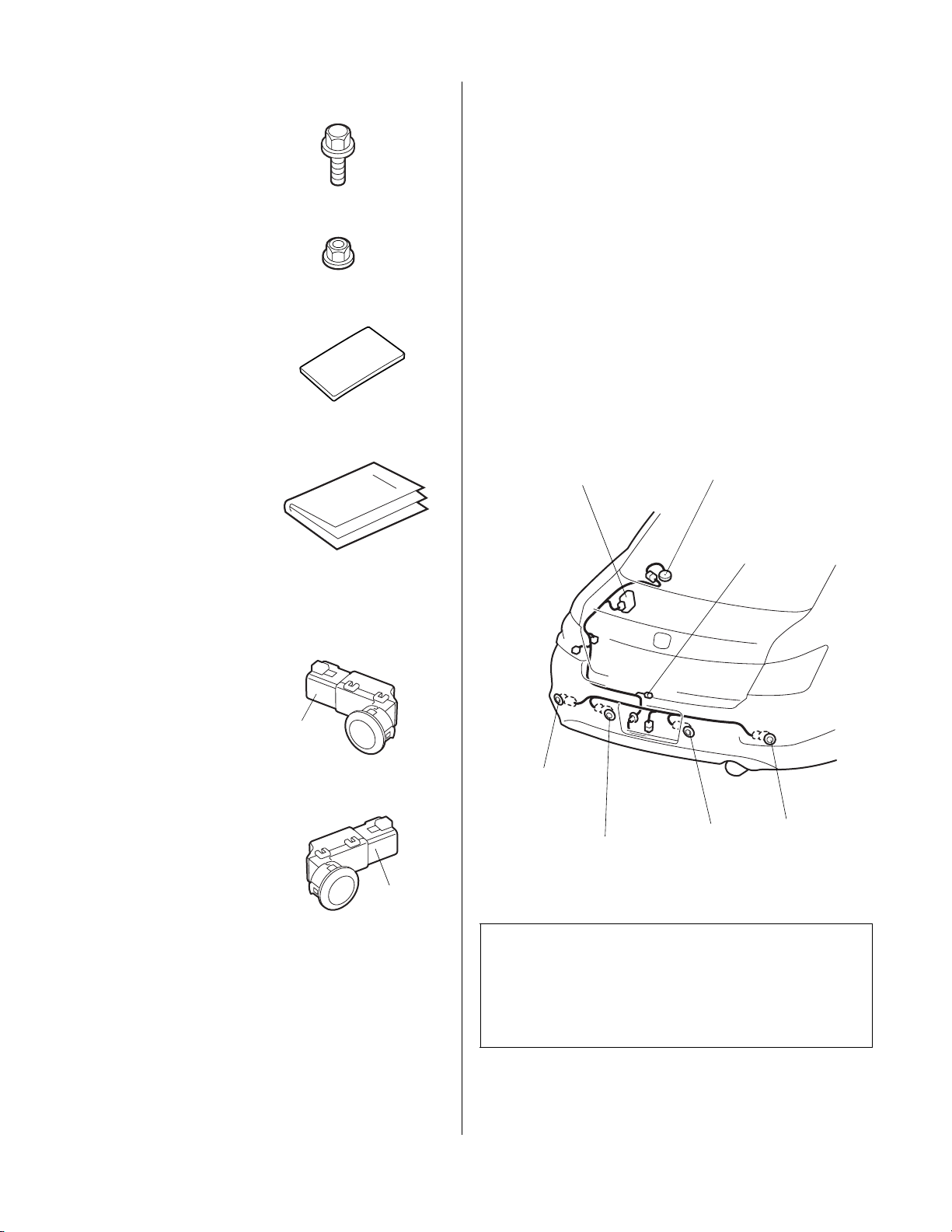
Flange bolt, 6 x 12 mm
www.collegehillshonda.com
Flange nut
4 Harness tapes
TOOLS AND SUPPLIES REQUIRED
Phillips screwdriver
Flat-tip screwdriver
Ratchet
8 mm and 10 mm Socket
Pushpin
Drill
3 mm Drill bit
24 mm and 26 mm Hole saw
Ruler
Eye protection (safety goggles, face shield, etc.)
10 mm Combination wrench
File
Trim tool TN SILTRIMTL10
Accessory User’s Information Manual
Back-up Sensor Kit
P/N 08V67-TE0-100K
2 Center sensors
(Blue)
2 Corner sensors
Illustration of the Back-up Sensor Installed on the Vehicle
CONTROL UNIT
LEFT
CORNER
SENSOR
(WHITE)
SENSOR (BLUE)
BUZZER
2A FUSE
CASE
RIGHT CENTER
SENSOR (BLUE)LEFT CENTER
RIGHT
CORNER
SENSOR
(WHITE)
742308AE
(White)
INSTALLATION
1. Make sure you have the anti-theft code for the radio
2 of 15 AII 37561-38377 (0711) © 2007 American Honda Motor Co., Inc. – All Rights Reserved.
Customer Information: The information in this
installation instruction is intended for use only by skilled
technicians who have the proper tools, equipment, and
training to correctly and safely add equipment to your
vehicle. These procedures should not be attempted by
“do-it-yourselfers.”
and navigation system (if equipped), then write down
the radio presets.
Page 3
2. Disconnect the negative cable from the battery.
www.collegehillshonda.com
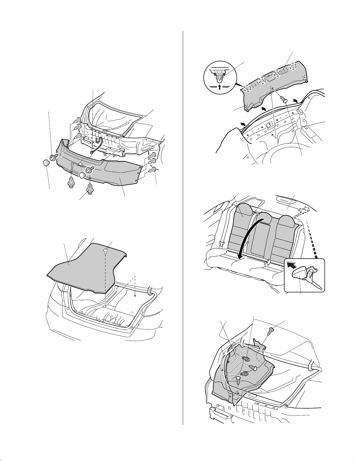
3. Remove the two covers from the rear bumper and
remove the rear bumper (two bolts, six self-tapping
screws, two clips, and unplug one connector).
NOTE: Have an assistant help you remove the rear
bumper.
CONNECTOR
5. Remove the rear trim panel (five clips and three
hooks).
REAR TRIM PANEL
4 CLIPS
2 BOLTS
2 COVERS
2 CLIPS
6 SELF-TAPPING
SCREWS
REAR
BUMPER
4. Remove the trunk floor mat (one clips).
TRUNK
FLOOR MAT
CLIP
742003CB
3 HOOKS
CLIP
6. Fold down the rear seat back by pulling the lever
under the rear shelf inside the trunk.
REAR SEAT BACK
REAR SHELF
742416BE
© 2007 American Honda Motor Co., Inc. – All Rights Reserved. AII 37561-38377 (0711) 3 of 15
LEVER (Pull.)
7. Remove the left trunk side lining (five clips).
LEFT TRUNK
SIDE LINING
2 CLIPS
3 CLIPS
Page 4
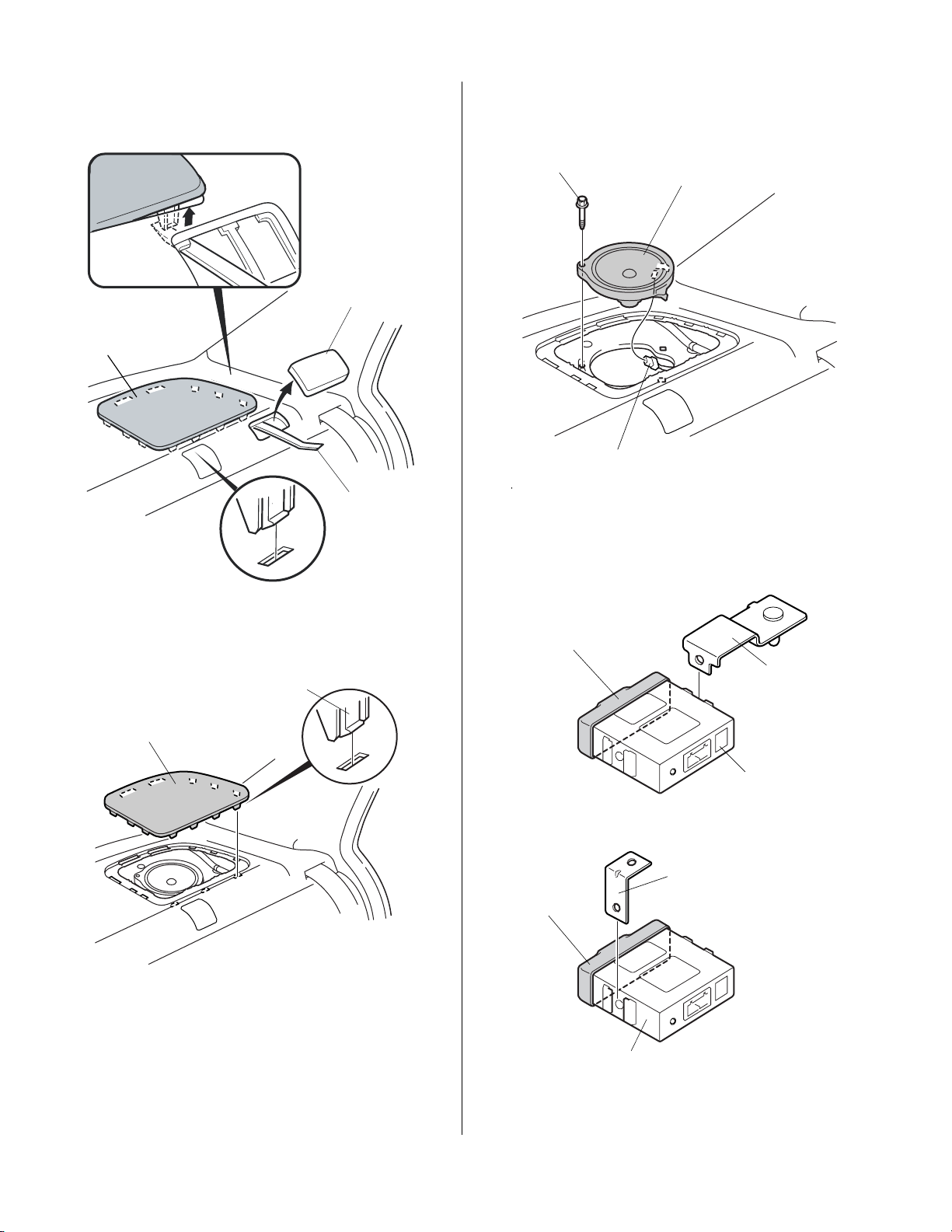
8. Using the trim tool, remove the rear shelf access
www.collegehillshonda.com
panel, then release the front rear speaker retaining
tab.
10. Remove the left rear speaker (one bolt and
disconnect the vehicle connector).
REAR SHELF
ACCESS PANEL
LEFT REAR
SPEAKER COVER
TRIM TOOL
(TN SILRIMTL10)
9. Remove the left rear speaker cover (nine retaining
tabs).
BOLT
VEHICLE
CONNECTOR
LEFT REAR
SPEAKER
7115040E
11. Wrap urethane tape around the control unit at the
area shown. Then, attach the control unit bracket
into the control unit.
L4 MODEL
URETHANE
TAPE
LEFT REAR
SPEAKER
COVER
9 RETAINING
TABS
742418AE
V6 MODEL
URETHANE
TAPE
CONTROL
UNIT
CONTROL UNIT
BRACKET
CONTROL
UNIT
CONTROL UNIT
BRACKET
761205CE
4 of 15 AII 37561-38377 (0711) © 2007 American Honda Motor Co., Inc. – All Rights Reserved.
Page 5
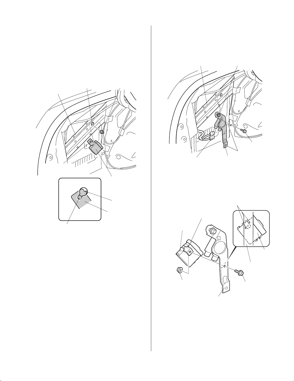
L4 Model
www.collegehillshonda.com
12. Install the control unit to the vehicle panel:
• Partially thread the 6 mm flange nut onto the
control unit bracket stud. Insert the control unit
bracket stud into the hole in the vehicle panel.
Tighten the 6 mm flange nut to secure the
bracket to the vehicle panel.
V6 MODEL
• Loosen the upper bolt from the relay support.
Remove the relay support (one bolt and
disconnect the vehicle connectors).
BOLT
VEHICLE PANEL
(Loosen.)
VEHICLE
PANEL
CONTROL UNIT
BRACKET STUD
BOLT
STUD BOLT
HOLE
6 mm
FLANGE NUT
CONTROL
UNIT
HOOK
CONTROL
UNIT
BRACKET
742311CE
BOLT
(Remove.)
VEHICLE CONNECTORS
RELAY
SUPPORT
771101AB
• Install the control unit bracket to the relay support
using the 6 x 12 mm flange bolt and the 6 mm
flange nut.
STOPPER
CONTROL UNIT
BRACKET
CONTROL
UNIT
© 2007 American Honda Motor Co., Inc. – All Rights Reserved. AII 37561-38377 (0711) 5 of 15
6 mm
FLANGE NUT
RELAY
SUPPORT
• Reinstall the relay support.
CONTROL
UNIT
RELAY
SUPPORT
6 x 12 mm
FLANGE BOLT
771102BB
Page 6

13. Attach the 2A fuse label to the fuse case on the
E
www.collegehillshonda.com
back-up sensor harness.
14. Disconnect the back-up light 2-pin connector from
the left taillight, and plug it into the back-up sensor
harness 2-pin connector. Plug the remaining
back-up sensor harness 2-pin connector into the left
taillight.
FUSE
CASE
2A FUSE LABEL
BACK-UP
SENSOR
HARNESS
742312A
LEFT TAILLIGHT
BACK-UP LIGHT
2-PIN CONNECTOR
BACK-UP
HARNESS
2-PIN
CONNECTOR
BACK-UP
HARNESS
CONNECTOR
BACK-UP SENSOR
HARNESS
6 of 15 AII 37561-38377 (0711) © 2007 American Honda Motor Co., Inc. – All Rights Reserved.
TRUNK ROOM
742313BE
Page 7

15. At the left taillight, secure the back-up sensor
www.collegehillshonda.com
harness to the vehicle harness with one wire tie.
BACK-UP
SENSOR
HARNESS
WIRE TIE
VEHICLE
HARNESS
BACK-UP
SENSOR
HARNESS
VEHICLE
HARNESS
742314BE
V6 MODEL
VEHICLE
HARNESS
GREEN TAPE
16. Plug the back-up sensor harness 14-pin connector
into the control unit, and route the harness forward
along the vehicle harness. Secure the back-up
sensor harness to the vehicle harness at the green
tape.
L4 MODEL
CONTROL
UNIT
GREEN
TAPE
WIRE
TIE
VEHICLE
HARNESS
BACK-UP SENSOR
HARNESS
CONTROL
UNIT
BACK-UP SENSOR
HARNESS 14-PIN
CONNECTOR
742315DE
BACK-UP SENSOR
HARNESS 14-PIN
CONNECTOR
WIRE
TIE
CONTROL
UNIT
CONTROL
UNIT
761301CE
© 2007 American Honda Motor Co., Inc. – All Rights Reserved. AII 37561-38377 (0711) 7 of 15
Page 8

17. Secure the back-up sensor harness to the vehicle
www.collegehillshonda.com
harness with two additional wire ties at the locations
shown.
L4 Model
2 WIRE TIES
VEHICLE
HARNESS
WIRE TIE
BACK-UP
SENSOR
HARNESS
VEHICLE
HARNESS
742401CE
BACK-UP SENSOR
HARNESS
V6 MODEL
VEHICLE
HARNESS
BACK-UP SENSOR
HARNESS
2 WIRE TIES
VEHICLE
HARNESS
WIRE TIE
BACK-UP SENSOR
HARNESS
771103BB
18. Secure the back-up sensor harness clip to the hole
in the vehicle panel.
8 of 15 AII 37561-38377 (0711) © 2007 American Honda Motor Co., Inc. – All Rights Reserved.
VEHICLE
PANEL
BACK-UP SENSOR
HARNESS CLIP
BACK-UP SENSOR
HARNESS
742402BE
Page 9

19. Using scissors cut one urethane tape in half, and
E
www.collegehillshonda.com
then cut one of the halves again. Wrap the cut pieces
around the beeper harness shown.
20. Install the connector clip to the beeper 2-pin
connector.
BEEPER 2-PIN
CONNECTOR
BEEPER 2-PIN
CONNECTOR
URETHANE
TAPE
23. Secure the beeper harness to the vehicle harness
with one wire tie.
WIRE TIE
VEHICLE
HARNESS
CONNECTOR
CLIP
URETHANE TAPE
Wrap the urethane tapes
around the harness.
URETHANE
TAPE
(Cut in half.)
2-PIN CONNECTOR
(Wrap from the end of
the 2-pin connector.)
BEEPER
720105BE
21. Using an isopropyl alcohol on a shop towel, clean
the vehicle panel where the beeper will attach.
BUZZER
ADHESIVE
BACKING
VEHICLE
PANEL HOLE
BEEPER
HARNESS
742406C
24. Plug the beeper 2-pin connector into the back-up
sensor harness 2-pin connector.
TRUNK LID HINGE
WIRE TIE
VEHICLE
HARNESS
Attachment
position.
BUZZER
HARNESS
742405CE
22. Remove the adhesive backing from the beeper, and
attach it to the opening in the left rear speaker at the
location shown. Route the beeper harness through
the hole in the rear shelf.
© 2007 American Honda Motor Co., Inc. – All Rights Reserved. AII 37561-38377 (0711) 9 of 15
BUZZER 2-PIN
CONNECTOR
BACK-UP SENSOR
HARNESS 2-PIN
CONNECTOR
URETHANE TAPE
Cut in quarter
2-PIN CONNECTOR
742407CE
25. Wrap the remaining piece of a urethane tape around
the connector.
26. Secure the 2-pin connection to the vehicle harness
with one wire tie.
27. Route the back-up sensor harness as shown and
secure it to the vehicle harness with three wire ties.
Page 10

WIRE
www.collegehillshonda.com
TIE
WIRE TIES
BACK-UP SENSOR
HARNESS
VEHICLE
HARNESS
28. Install one wire tie with clip to the holder with the fuse
case, and attach the wire tie to the vehicle harness.
FUSE
CASE
WIRE TIE
WITH CLIP
VEHICLE
GROMMET
VEHICLE
HARNESS
761402AE
29. Remove the vehicle grommet from the rear panel.
30. Route the back-up sensor 6-pin connector through
the hole in the rear panel, and seat the harness
grommet in the rear panel hole.
TRUNK ROOM
742408CE
BACK-UP
SENSOR
HARNESS
Hole from which
the grommet has
been removed.
VEHICLE
HARNESS
GROMMET
BACK-UP SENSOR
HARNESS
BACK-UP
SENSOR
HARNESS
6-PIN
CONNECTOR
WIRE TIE
Outside
GROMMET
Inside
742409BE
31. Secure the back-up sensor harness to the vehicle
10 of 15 AII 37561-38377 (0711) © 2007 American Honda Motor Co., Inc. – All Rights Reserved.
harness with one wire tie.
Page 11

32. Install one wire tie with holder to the back-up sensor
www.collegehillshonda.com
harness 16-pin connector, and attach the wire tie to
the vehicle harness.
NOTE: There are several markings on the inside of the
rear bumper. Before piercing the rear bumper, verify you
have the correct locations.
BACK-UP SENSOR
WIRE TIE WITH
HOLDER
VEHICLE
HARNESS
HARNESS
6-PIN CONNECTOR
33. Mark the inside of the rear bumper:
• Locate the three marks on the inside of the
bumper at the center and left side.
• Using a pushpin, pierce the rear bumper at the
top and center of the three marks.
• Locate the three marks on the inside rear
bumper on the right side.
• Using a pushpin, pierce the rear bumper at the
bottom and the center of the right mark.
742410BE
REAR BUMPER
PUSHPIN
REAR BUMPER
PUSHPIN
MARK
REAR BUMPER
MARK
3 MARKS
3 MARKS
742603BE
© 2007 American Honda Motor Co., Inc. – All Rights Reserved. AII 37561-38377 (0711) 11 of 15
Page 12

34. While wearing eye protection drill the rear bumper:
www.collegehillshonda.com
NOTE: Center sensors are 26 mm holes, side sensors are
24 mm holes.
• From the outside of the bumper, drill all eight
pierced marks using a 3 mm drill bit.
• Using a 24 mm hole saw, enlarge the lower
outboard hole on the left side of the bumper.
Remove all burrs.
DRILL
(3 mm
DRILL BIT)
HOLE
LOWER
HOLE
24 mm
HOLE SAW
• Using 26 mm holes saw, enlarge both lower in
board bumper holes at the center of the bumper.
Remove all burrs.
LOWER
HOLE
DRILL
(26 mm
HOLE SAW)
REAR BUMPER
DRILL
(3 mm
DRILL BIT)
HOLE
REAR BUMPER
BURRS
(Remove.)
771104AB
• Using a 24 mm hole saw, enlarge the upper
outboard hole on the left side of the bumper.
Remove all burrs.
DRILL
24 mm
HOLE SAW
DRILL
3 mm
DRILL BIT
UPPER HOLE
HOLE
REAR BUMPER
BURRS
(Remove.)
771106AB
35. Install the two corner sensors into the 24 mm holes
in the rear bumper using the sensor clips. Not the
direction and the pin location for each sensor.
CORNER
Inside
SENSOR
CLIP
SENSOR
(White)
REAR
BUMPER
742412AE
Outside
CORNER
SENSOR
(White)
24 mm HOLE
REAR
BUMPER
CORNER
SENSOR
(White)
Inside
24 mm
HOLE
REAR
BUMPER
Outside
CORNER
SENSOR
(White)
SENSOR
CLIP
BURRS
(Remove.)
771105AB
12 of 15 AII 37561-38377 (0711) © 2007 American Honda Motor Co., Inc. – All Rights Reserved.
Page 13

36. Install two center sensors into the 26 mm holes in the
www.collegehillshonda.com
rear bumper using the sensor clips. Note the
direction and location for each sensor.
REAR
BUMPER
REAR
BUMPER
Outside Inside
SENSOR
CLIP
BACK-UP SENSOR
SUBHARNESS
2 BACK-UP SENSOR
SUBHARNESS CLIPS
SENSOR
CLIP
2 CENTER
SENSORS
(Blue)
2 HOLES,
26 mm
2 CENTER SENSORS
(Blue)
SENSOR CLIP
742413BE
37. Plug the four back-up sensor subharness 2-pin
connectors into each back-up sensor connector.
NOTE: The back-up sensor harness 6-pin connector
and the junction connector must be positioned on the
left side of bumper.
RIGHT CENTER
CORNER
SENSOR
SENSOR
LEFT CENTER
SENSOR
CORNER
SENSOR
HOLDER
CLIP
WIRE TIE
WITH CLIP
BACK-UP SENSOR
SUBHARNESS
JUNCTION CONNECTOR
BACK-UP
SENSOR
HARNESS
742602CE
39. Secure the subharness to the bumper using four
harness tapes in the locations shown.
40. Attach one wire tie with holder clip to the back-up
sensor subharness junction connector and secure
the wire tie to the vehicle harness.
4 BACK-UP SENSOR
SUBHARNESS 2-PIN
CONNECTORS
BACK-UP SENSOR
SUBHARNESS
JUNCTION
CONNECTOR
BACK-UP SENSOR
HARNESS 6-PIN
CONNECTOR
742601BE
38. Attach the two center backup sensor subharness
clips to the holes in each center sensor clip.
© 2007 American Honda Motor Co., Inc. – All Rights Reserved. AII 37561-38377 (0711) 13 of 15
Page 14

41. Using isopropyl alcohol on a shop towel, clean the
www.collegehillshonda.com
area where the harness tapes will attach.
4 GREEN
TAPES
BACK-UP SENSOR
SUBHARNESS
BACK-UP SENSOR
SUBHARNESS
6-PIN CONNECTOR
CORNER
SENSOR
BACK-UP SENSOR
HARNESS
6-PIN CONNECTOR
4 HARNESS
TAPES
771107BB
42. At each green tape location, attach the back-up
sensor subharness to the rear bumper with four
harness tapes.
43. Plug the back-up sensor harness 6-pin connector
into the back-up sensor subharness 6-pin connector,
then reinstall the rear bumper. .
NOTE: Have an assistant help you install the rear
bumper
LEFT
CENTER
SENSOR
RIGHT
CENTER
SENSOR
CORNER
SENSOR
REAR
BUMPER
761302AE
14 of 15 AII 37561-38377 (0711) © 2007 American Honda Motor Co., Inc. – All Rights Reserved.
Page 15

44. Check that all wire harnesses are routed properly
www.collegehillshonda.com
and that all connectors are plugged in.
45. Reinstall all removed parts.
46. Reconnect the negative cable to the battery.
47. Enter the anti-theft codes for the radio and
navigation systems (if equipped), then enter the
customer’s radio presets.
48. Reset the clock.
49. Check that the back-up sensors work properly as
described in the Accessory User’s Information
Manual supplied.
Beeper Volume Control
Factory setting of the volume control knob on the control
unit is turned to maximum volume. After confirming the
operation check, turn the volume control knob to the
appropriate volume.
CONTROL
UNIT
VOLUME
CONTROL
KNOB
Volume
up.
Volume
down.
771108AB
© 2007 American Honda Motor Co., Inc. – All Rights Reserved. AII 37561-38377 (0711) 15 of 15
 Loading...