

Page 1
INSTALLATION
www.collegehillshonda.com
INSTRUCTIONS
Accessory Application Publications No.
AII 38137-38714
2008 ODYSSEYAccessory HandsFreeLink
Issue Date
JAN 2008
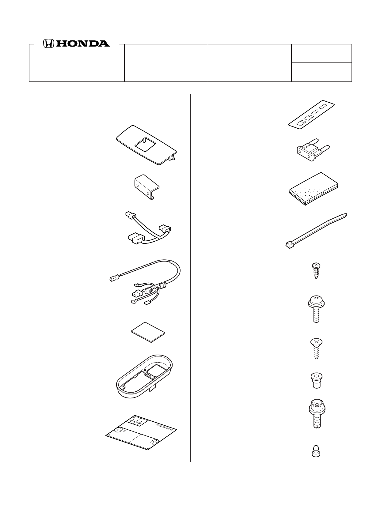
PARTS LIST
HFL Attachment Kit
P/N 08E02-SHJ-100B
HFL trim
HFL bracket
HFL harness
HFL subharness
Fuse label
Fuse (2 A)
6 EPT sealers
8 Wire ties
4 Self-tapping screw, 3 x 10 mm
2 Double-faced tapes
HFL retainer
Template
2 Washer screws, 4 x 12 mm
Self-tapping screw
Bush
Ground bolt
Rubber bumper
© 2008 American Honda Motor Co., Inc. - All Rights Reserved. AII 38137-38714 (0801) 1 of 1208E02-SHJ-1B00-91
Page 2
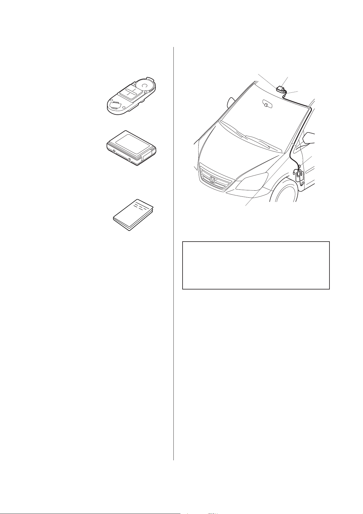
HFL Blue Tooth Kit
www.collegehillshonda.com
P/N 08E00-E10-100
Illustration of the HFL Installed on the Vehicle
Switch
Control unit
Accessory User's Information Manual
INSTALLATION
SWITCH
HFL
SUBHARNESS
CONTOROL
UNIT
HFL
HARNESS
FUSE
(2 A)
7518071E
TOOL AND SUPPLIES REQUIRED
#2 Phillips screwdriver
10 mm Combination wrench
10 mm and 14 mm Socket
Pushpin
Ratchet
3 mm, 4.5 mm, 6 mm, 9 mm, and 10 mm Drill bit
Eye protection (face shield, safety goggles, etc.)
File
Diagonal cutters
Scissors
Masking tape
Tape measure
Cardboard
Isopropyl alcohol
Shop towel
19 mm Holesaw
Drill
Utility knife
T15 Torx bit
Felt-tip pen
Plastic trim tool SILTRIMTL10
Customer Information: The information in this
installation instruction is intended for use only by
skilled technicians who have the proper tools,
equipment, and training to correctly and safely add
equipment to your vehicle. These procedures
should not be attempted by “do-it-yourselfers.”
1. Make sure you have the anti-theft code for the
radio, then write down the frequencies for the
preset buttons.
2. Disconnect the negative cable from the battery.
2 of 12 AII 38137-38714 (0801) © 2008 American Honda Motor Co., Inc. - All Rights Reserved.
Page 3
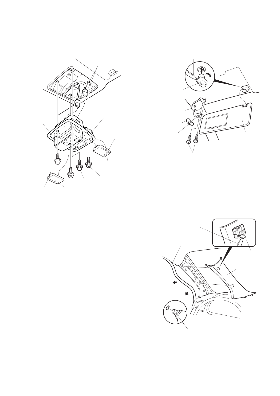
3. Disengage eight retaining tabs and remove left
www.collegehillshonda.com
and right lens from the roof console.
7. Using a flat-tip screwdriver, push the hook and
turn the holder. Remove the holder.
SUNGLASS
HOLDER
(Open.)
2 BOLTS
4 RETAINING
TABS
LEFT
LENS
4. Open the sunglass holder.
VEHICLE
CONNECTORS
ROOF
CONSOLE
RIGHT
LENS
4 RETAINING
TABS
2 BOLTS
7517010E
PLASTIC TRIM TOOL
SUNVISOR
HOLDER
VEHICLE
CONNECTOR
COVER
RETAINING
TAB
2 SCREWS
LEFT
SUNVISOR
8. Disengage two screws and remove the left
sunvisor.
9. Pull away the weatherstrip from the left front Apillar trim. Release the side curtain air bag clip by
using the plastic trim tool and remove the left front
A-pillar (two clips).
5. Remove four bolts and lower the roof console.
6. Disconnect the two vehicle connectors and
remove the roof console.
PLASTIC TRIM
TOOL
WEATHERSTRIP
SIDE CURTAIN
AIR BAG CLIP
LEFT FRONT
A-PILLAR TRIM
CLIP
© 2008 American Honda Motor Co., Inc. - All Rights Reserved. AII 38137-38714 (0801) 3 of 12
Page 4
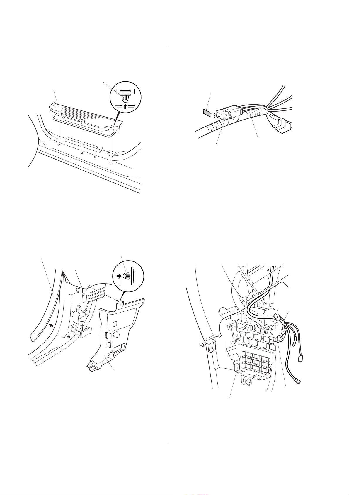
10. Remove the left front door sill trim (three clips).
www.collegehillshonda.com
12. Attach the fuse label (2 A) to the fuse case of the
HFL subharness.
LEFT FRONT
DOOR SILL TRIM
3 CLIPS
4301210B
11. Pull away the weatherstrip from the left kick panel.
Remove the left kick panel (three clips).
FUSE LABEL (2 A)
HFL
SUBHARNESS
FUSE CASE
HFL
SUBHARNESS
7821100B
13. Plug the HFL subharness 6-pin connector into the
6-pin opening in the fuse box.
WEATHERSTRIP
3 CLIPS
LEFT KICK
PANEL
4301221B
FUSE
BOX
HFL
SUBHARNESS
6-PIN
CONNECTOR
7517042E
4 of 12 AII 38137-38714 (0801) © 2008 American Honda Motor Co., Inc. - All Rights Reserved.
Page 5

7517051E
7517072E
NOTE: If another accessory is already plugged into the
www.collegehillshonda.com
6-pin connector, remove the dummy connector
from the 6-pin connector taped to the HFL
subharness. Plug the 6-pin connector from the
other accessory harness into the 6-pin
connector from the HFL subharness you just
unplugged and plug the HFL subharness into
the fuse box.
FUSE BOX
HFL
SUBHARNESS
6-PIN
CONNECTOR
DUMMY
CONNECTOR
16. Remove the vehicle bolt (discard) and install the
ground bolt with HFL subharness ground terminal
as shown.
GROUND
BOLT
FUSE
BOX
FUEL
OPENER
HFL SUBHARNESS
GROUND TERMINAL
HOOD
OPENER
VEHICLE
BOLT
(Discard.)
OTHER ACCESSORY
6-PIN CONNECTOR
4319060B
14. Route the HFL subharness to the left front pillar
trim opening.
HFL
SUBHARNESS
HFL
SUBHARNESS
WIRE
TIE
GREEN
TAPE
VEHICLE
HARNESS
VEHICLE
CLIP
VEHICLE
HARNESS
17. Disconnect the vehicle harness 1-pin connector
and connect it to the HFL subharness 1-pin
connector.
VEHICLE
HARNESS 1-PIN
CONNECTOR
HFL SUBHARNESS
1-PIN CONNECTOR
EPT
SEALER
LEFT FRONT
PILLAR TRIM
OPENING
7517031E
15. Route the HFL subharness and secure the
harness to the vehicle harness with a wire tie
above the vehicle clip as shown.
© 2008 American Honda Motor Co., Inc. - All Rights Reserved. AII 38137-38714 (0801) 5 of 12
EPT
SEALER
Cut in half.
HFL
SUBHARNESS
HFL SUBHARNESS
CONNECTION PART
18. Connect the HFL subharness 1-pin connector to
the vehicle 1-pin connector.
19. Wrap the cut one half of the EPT sealer on the
HFL subharness connection part.
Page 6

20. Secure the HFL subharness to the vehicle
www.collegehillshonda.com
harness with a wire tie.
VEHICLE
PANEL
WIRE TIE
HFL
SUBHARNESS
EPT
SEALER
23. Cut the template into template A and template B.
TEMPLATE A
TEMPLATE
TEMPLATE B
7517091E
VEHICLE
HARNESS
7517061E
21. Using isopropyl alcohol on a shop towel, clean the
area where the EPT sealer will attach. Attach a
EPT sealer to secure the HFL subharness to the
vehicle panel.
22. Secure the HFL subharness to the vehicle
harness with three wire tie.
HFL
SUBHARNESS
3 WIRE
TIES
VEHICLE
HARNESS
24. Remove the damper (two tapping screws).
SUNGLASSES
HOLDER
ROOF
CONSOLE
VEHICLE
BUSHES
PIN
TAPPING
SCREW
CAMSET
LOCK
2 TAPPING
SCREWS
2 RETAINING
TABS
DAMPER
7517101E
25. Remove the sunglasses holder (tapping screw and
vehicle bushes).
26. Remove the pin and remove the camset lock (two
retaining tabs).
7517080E
6 of 12 AII 38137-38714 (0801) © 2008 American Honda Motor Co., Inc. - All Rights Reserved.
Page 7

7517112E
27. Remove the console light from the roof console
www.collegehillshonda.com
(four retaining tabs).
29. Attach masking tape to the roof console as
shown.
ROOF
CONSOLE
4 RETAINING
TABS
CONSOLE
LIGHT
7523030E
28. Enlarge the hole on the roof console with 9 mm
drill bit.
ROOF
CONSOLE
MASKING
TAPE
ROOF
CONSOLE
7716020X
30. Attach template A with masking tape to the roof
console at the indicated position.
ROOF
CONSOLE
PUSHPIN
CENTER OF THE
ROOF CONSOLE
FELT-TIP
PEN
MARK
MASKING
TAPE
2 MARKS
TEMPLATE A
31. Using a felt-tip pen, mark the center of the roof
DRILL BIT
(9 mm)
console as shown.
32. Use a pushpin to mark the roof console at two
locations according to template A.
7524060E
© 2008 American Honda Motor Co., Inc. - All Rights Reserved. AII 38137-38714 (0801) 7 of 12
33. Remove template A.
Page 8

34. Drill 4.5 mm holes at the two locations marked on
www.collegehillshonda.com
the roof console in step 32. After drilling, remove
any burrs.
39. Drill a 3 mm hole at the four locations marked on
the roof console in step 36.
DRILL BIT
(4.5 mm)
ROOF
CONSOLE
2 MARKS
7517120E
35. Attach template B with masking tape on the roof
console at the indicated position.
19 mm
HOLE SAW
4 MARKS
DRILL BIT
(3 mm)
ROOF
CONSOLE
DRILL BIT
(3 mm 6 mm
10 mm)
DRILL
7517141E
PUSHPIN
4 MARKS
MASKING
TAPE
ROOF
CONSOLE
CENTER OF THE
ROOF CONSOLE
FELT-TIP
PEN
TEMPLATE B
PUSHPIN
7517131E
36. Use a pushpin to mark the roof console at four
locations according to template B.
37. Use a felt-tip pen and mark the roof console along
the template B.
40. Enlarge the two 3 mm holes drilled in step 39 with
a 6 mm drill bit and with a 10 mm drill bit as
shown.
41. Enlarge the other two 3 mm holes drilled in step
39 with a 19 mm hole saw as shown.
38. Remove template B.
8 of 12 AII 38137-38714 (0801) © 2008 American Honda Motor Co., Inc. - All Rights Reserved.
Page 9

7517171E
42. Using a utility knife, cut along the marking made
www.collegehillshonda.com
on the roof console in step 37. After cutting,
remove any burrs.
ROOF
CONSOLE
Mark made in
step 37.
UTILITY
KNIFE
45. Connect the HFL harness 22-pin connector to the
control unit.
CENTER
CONTROL
UNIT
Cut out.
ROOF
CONSOLE
Cut out.
7517152E
43. Remove the masking tape attached in step 29.
44. Using isopropyl alcohol on a shop towel, clean the
areas where the double-faced tape will attach.
Remove the adhesive backing from double-faced
tape and attach the double-faced tape at the
indicated position on the control unit.
2 DOUBLE-FACED
TAPES
CONTROL
UNIT
ROOF
CONSOLE
Remove the
adhesive
backing.
HFL
HARNESS
HFL HARNESS
22-PIN
CONNECTOR
ROOF
CONSOLE
46. Using isopropyl alcohol on a shop towel, clean the
areas where the double-faced tape will attach.
Remove the adhesive backing from the doublefaced tape attached to the control unit and attach
to the roof console at the indicated position.
47. Use the holes drilled in step 34 and secure the
HFL bracket with two 4 x 12 mm washer screws to
the roof console.
Holes drilled
in step 34.
CONTROL
UNIT
10 mm
© 2008 American Honda Motor Co., Inc. - All Rights Reserved. AII 38137-38714 (0801) 9 of 12
10 mm
CONTROL
UNIT
7517161E
2 WASHER
SCREWS,
4 x 12 mm
HFL
BRACKET
ROOF
CONSOLE
7517180E
Page 10

48. Bend the switch terminal as shown.
www.collegehillshonda.com
BACKSIDE OF THE SWITCH
SPEAKER
SWITCH
TERMINAL
SWITCH
SWITCH
TERMINAL
(Bend.)
HFL TRIM
51. Connect the HFL harness 20-pin connector to the
switch.
SELF- TAPPING
SCREW (Reuse.)
SWITCH
VEHICLE
BUSHES
(Reuse.)
HFL
RETAINER
4 SELF-TAPPING
SCREWS,
3 x 10 mm
RUBBER
BUMPER
HFL
RETAINER
791209AB
49. Insert the rubber bumper to the HFL retainer.
50. Assemble HFL retainer, switch, and HFL trim with
four 3 x 10 mm self-tapping screws.
HFL HARNESS
20 -PIN
CONNECTOR
ROOF
CONSOLE
BUSHES
SELF- TAPPING
SCREW
7517192E
52. Install the switch assembled in step 50 to the roof
console with self-tapping screw, bushes, tapping
screw removed in step 25 and vehicle bushes.
53. Reinstall the console light to the roof console.
54. Using isopropyl alcohol on a shop towel, clean
the area where the EPT sealer will attach. Cut an
EPT sealer in half and attach one half to the
vehicle bracket as shown.
ROOF CONSOLE
OPENING
VEHICLE
BRACKET
EPT SEALER
(Cut in half.)
EPT SEALER
10 of 12 AII 38137-38714 (0801) © 2008 American Honda Motor Co., Inc. - All Rights Reserved.
7518010E
Page 11

2219080T
55. Hold the roof console close to the roof console
www.collegehillshonda.com
opening and connect the HFL harness 4-pin
connector to the HFL subharness 4-pin connector.
58. Connect the vehicle connectors to the roof
console. Reinstall the roof console with the four
bolts from step 5.
GREEN
CONNECTOR
VEHICLE
BRACKET
HFL
SUBHARNESS
4-PIN
CONNECTOR
HFL HARNESS
4-PIN
CONNECTOR
ROOF
CONSOLE
WIRE TIE
Vehicle front
ROOF
CONSOLE
OPENING
7518020E
VEHICLE
CONNECTORS
ROOF
CONSOLE
7518042E
2 BOLTS
2 BOLTS
59. Install the fuse (2 A) into the fuse box at the
indicated position.
56. Secure the connector with a wire tie to the vehicle
bracket.
57. Using isopropyl alcohol on a shop towel, clean the
area where the EPT sealer will attach. Secure the
HFL subharness to the vehicle roof panel inside
the roof lining with three EPT sealers.
3 EPT
SEALERS
HFL
ROOF
PANEL
SUBHARNESS
7518030E
FUSE BOX
FUSE (2 A)
© 2008 American Honda Motor Co., Inc. - All Rights Reserved. AII 38137-38714 (0801) 11 of 12
Page 12

60. Attach the fuse label to the No. 33 slot on the fuse
www.collegehillshonda.com
box cover.
61. Check that all wire harnesses are routed properly
and that all connectors are plugged in.
FUSE BOX
COVER
FUSE LABEL
(OPITION FUSE 2 A)
No. 33
62. Reinstall all removed parts.
63. Reconnect the negative cable to the battery.
64. Enter the customer’s radio anti-theft code, and
reset the radio station presets.
65. Reset the clock.
NOTE: When the battery is disconnected, the driver’s
window AUTO function is disabled.
• Start the engine. Push down on the driver’s window
switch until the window is fully open.
• Pull up on the driver’s window switch to close the
window completely, then hold the switch for
1 second or more.
• Lower and raise the driver’s window to check
operation of the driver’s window AUTO function.
2219090T
12 of 12 AII 38137-38714 (0801) © 2008 American Honda Motor Co., Inc. - All Rights Reserved.
 Loading...