How it Works
Log In / Sign Up
Buy Points
How it Works
FAQ
Contact Us
Questions and Suggestions
Users
Honda
Loading...
U
UMK431
3
UMK431E
UMK435
UMK435E
3
UMK435E1
2
UMK435E3
UMK435T
2
UMK435U
UMK450E
UMK450ELEET
UMK450EUEET
UMK450EXEET
UMR 435 T
3
UMS425E
UMS 425E LN
UMS425U
UT2
V
V30 Magna
V30 Magna (1984)
V30 Magna (1985)
V30 Magna VF500C (1984)
V30 Magna VF500C (1985)
V45 700 Magna (1982)
V45 700 Magna (1983)
V45 700 Magna (1984)
V45 700 Magna (1985)
V45 700 Magna (1986)
V45 700 Magna (1987)
V45 700 Magna (1988)
V45 700 Sabre (1983)
V45 700 Sabre (1984)
V45 700 Sabre (1985)
V45 750 Magna (1982)
V45 750 Magna (1983)
V45 750 Magna (1984)
V45 750 Magna (1985)
V45 750 Magna (1986)
V45 750 Magna (1987)
V45 750 Sabre (1982)
V45 750 Sabre (1983)
V45 750 Sabre (1984)
V45 750 Sabre (1985)
V45 Magna (1982)
V750C (2005)
Varadero MK1 XL 1000 V
Varadero XL1000V
Vehicle
Vehicle Entertainment System
Vezel
VF1000F
VF1000F II 1985
VF1100 C
VF500C (1984)
VF500C (1984-1985)
VF500C (1985)
VF500F
VF500F 1983
VF500F 1984
VF500F 1985
VF500FII 1985
VF700C Magna 1987
23
VF750C
2
VF750C (1994)
VF 750 C 1994 2003
VF750C 1996
VF750C5
VF 750 CD 1994 2003
VF750CD Magna (1995)
VF750C Magna (1995)
VF 750F '83 '84
VF750FD 1984
VF750S-C Sport (1982)
VF750S-C Sport (1983)
VF750S-C Sport (1984)
VFC
2
VFH-ABS
VFR
4
VFR 1200F
2
VFR1200F (2010)
VFR1200F (2011)
VFR1200FA (2009)
VFR1200FD
VFR1200FD (2010)
VFR1200F-FD
VFR 1200X
VFR (2002)
VFR (2009)
VFR 400
5
VFR 400R
6
VFR 400R SS-SP '92
VFR 750f 90-96
VFR 800
5
VFR-ABS
4
VFR-ABS (2002)
VFR-ABS 2005
VFR-ABS 2006
VFR-ABS 2007
VFR-ABS 2008
VFR-ABS (2009)
V-TWIN CUSTOM
Loading...
Loading...
Nothing found
VF 750 C 1994 2003
Service manual
306 pgs
13.75 Mb
0
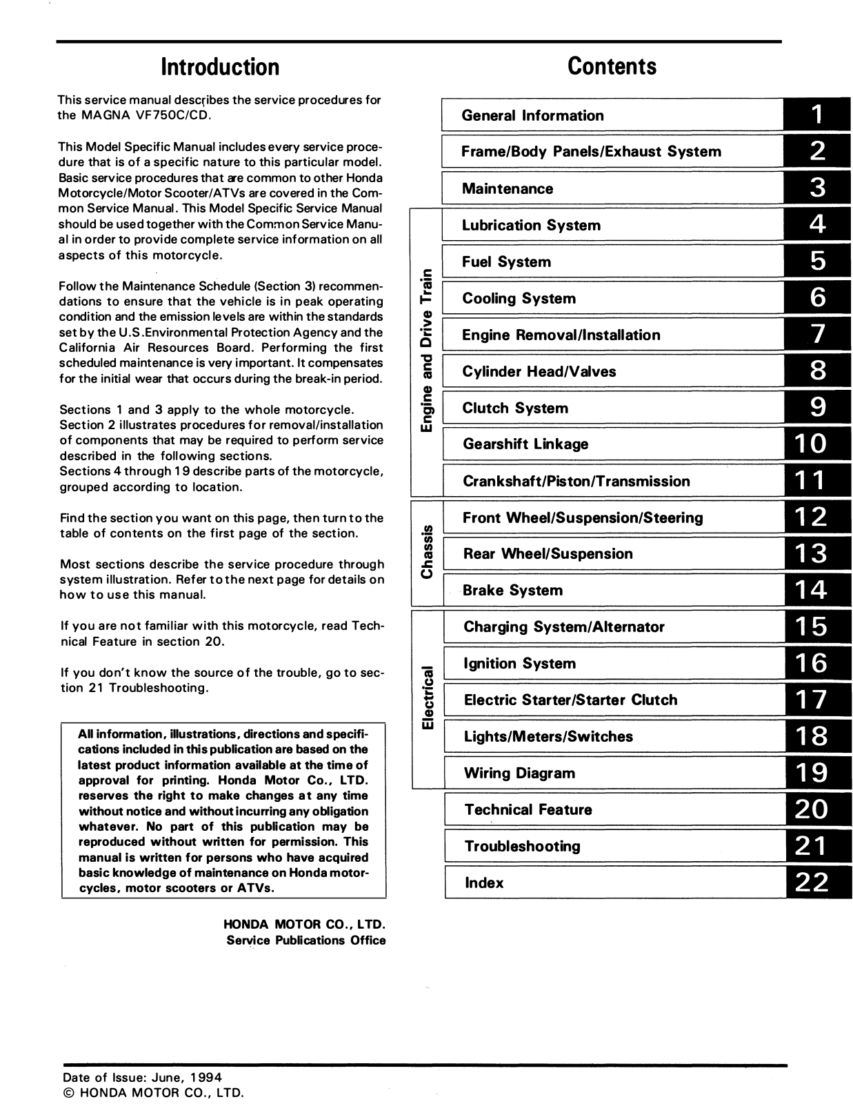
Table of contents
Loading...
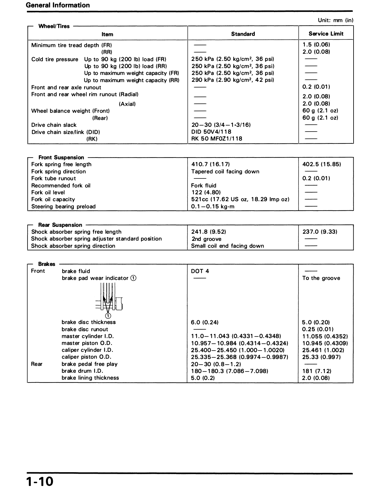
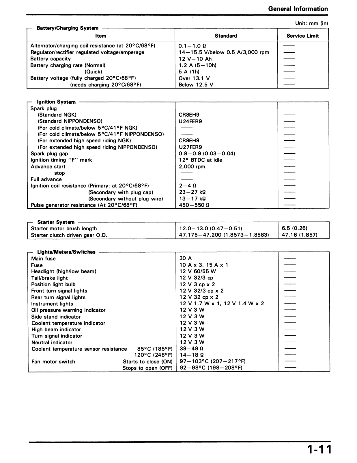
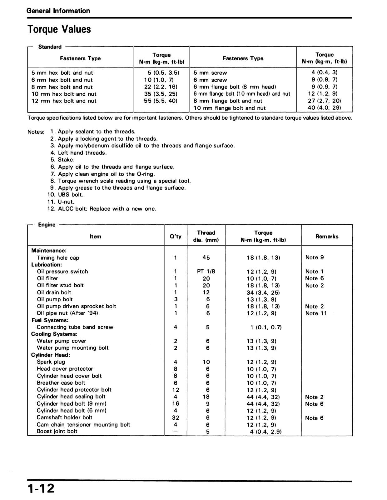
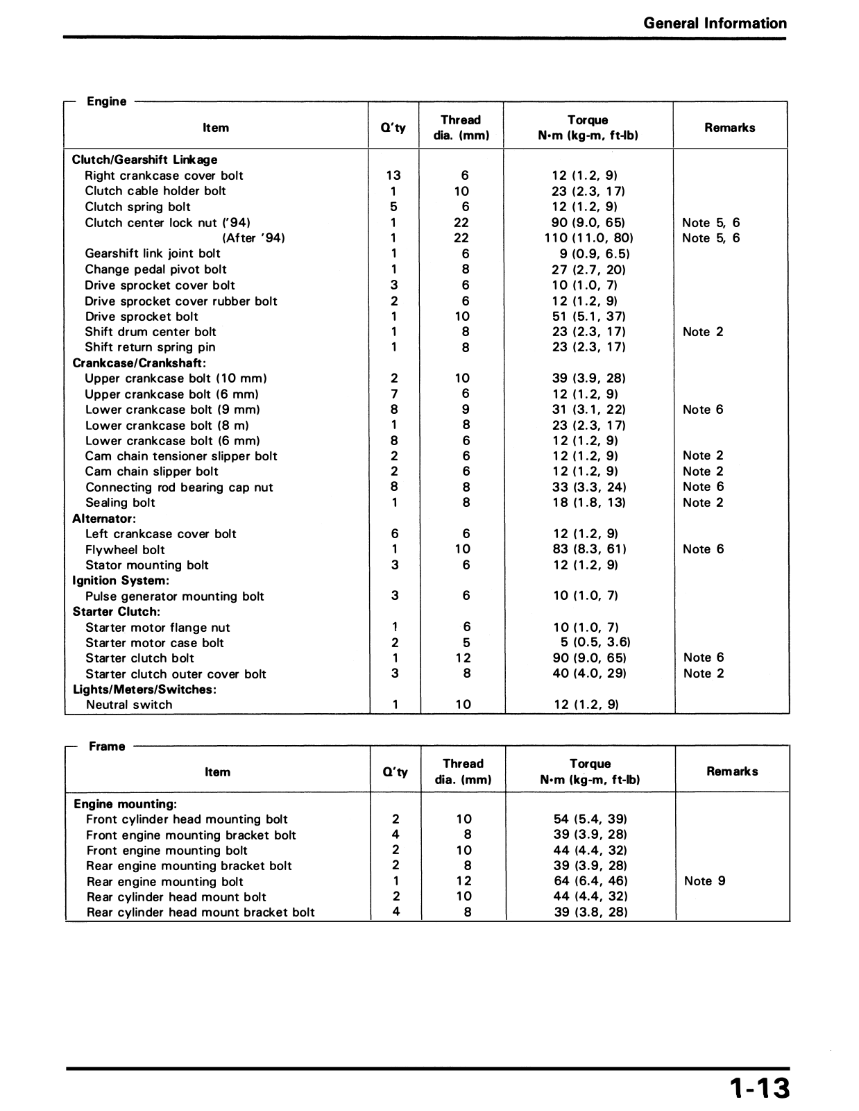
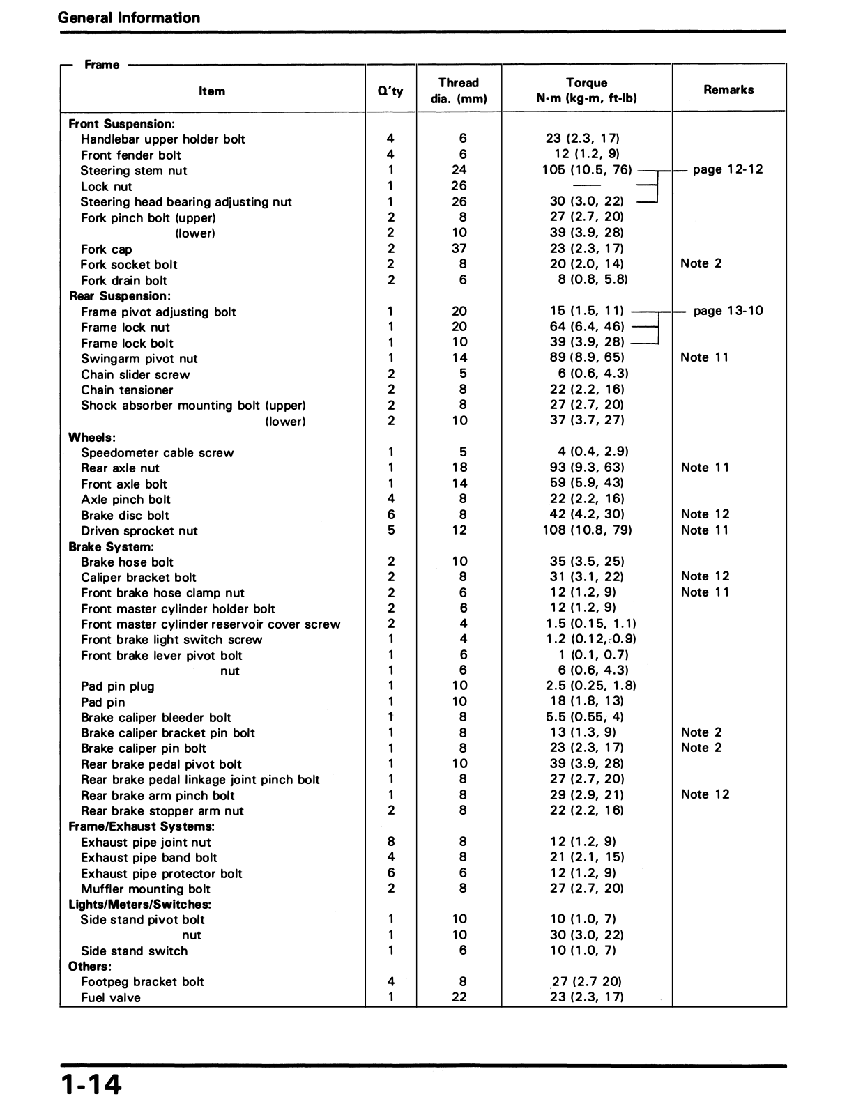
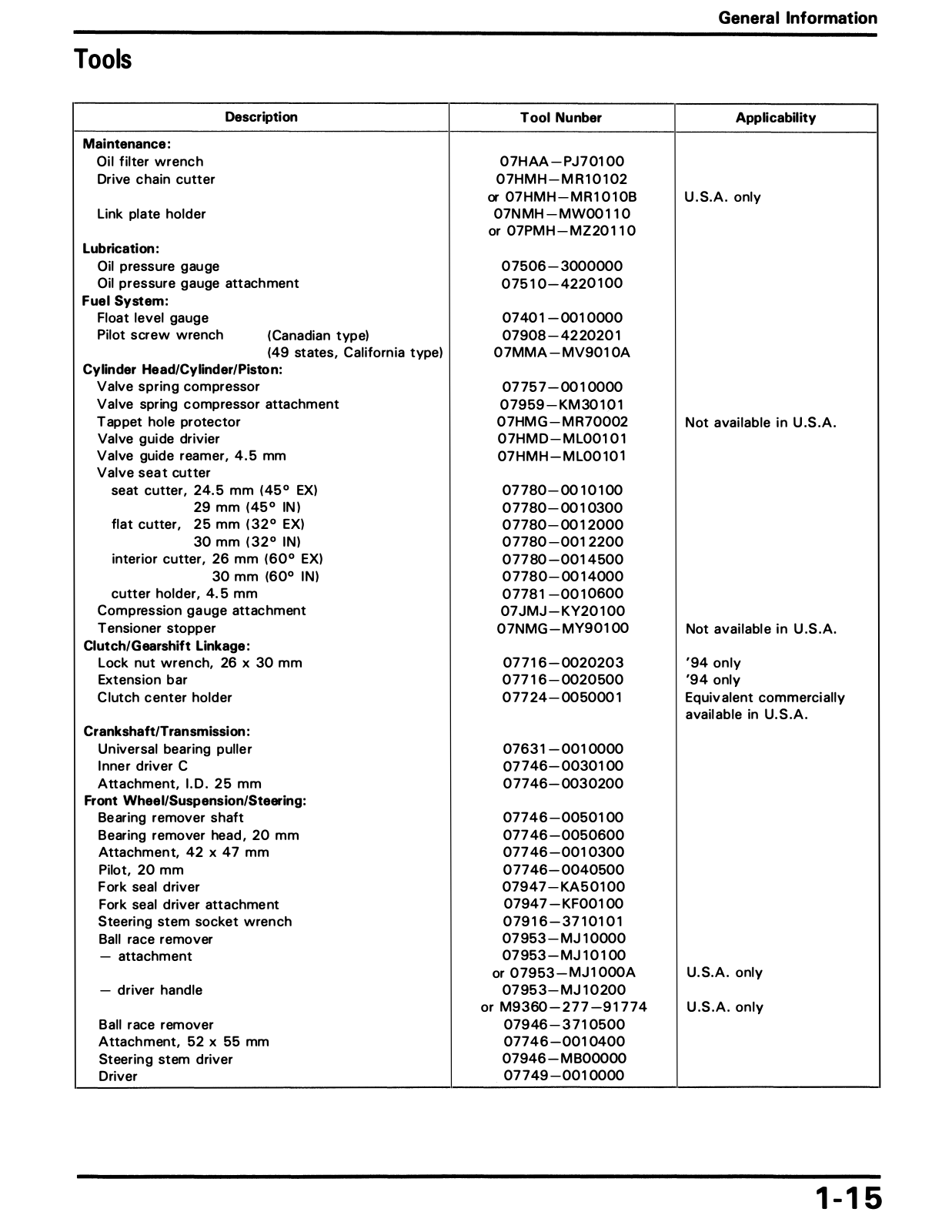
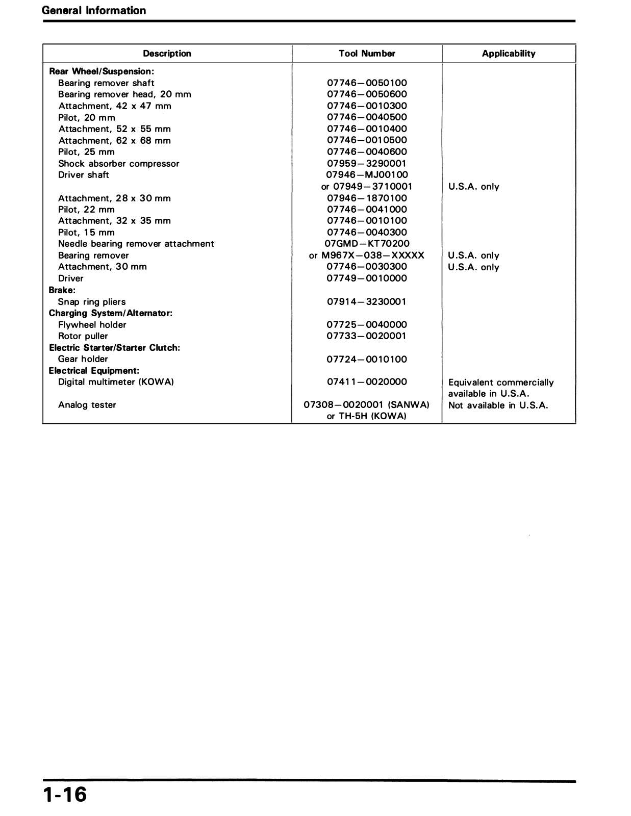
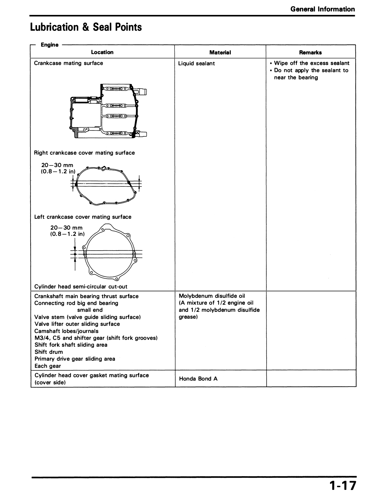
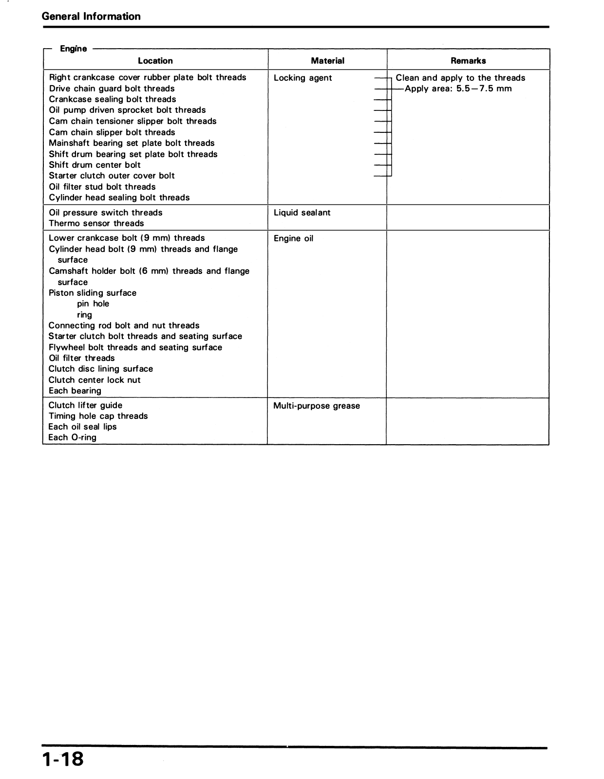
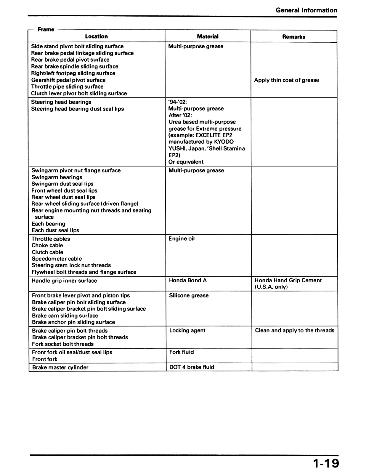
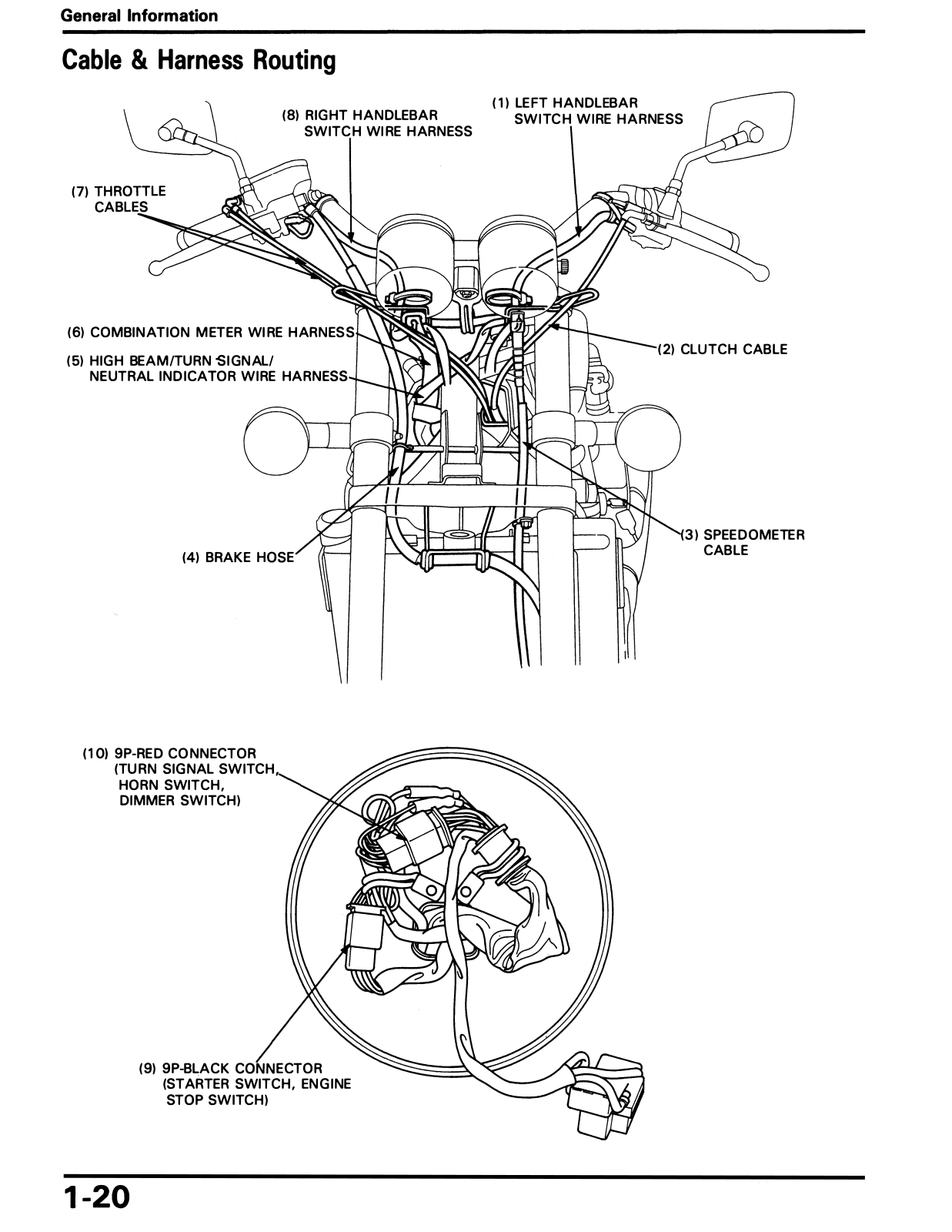
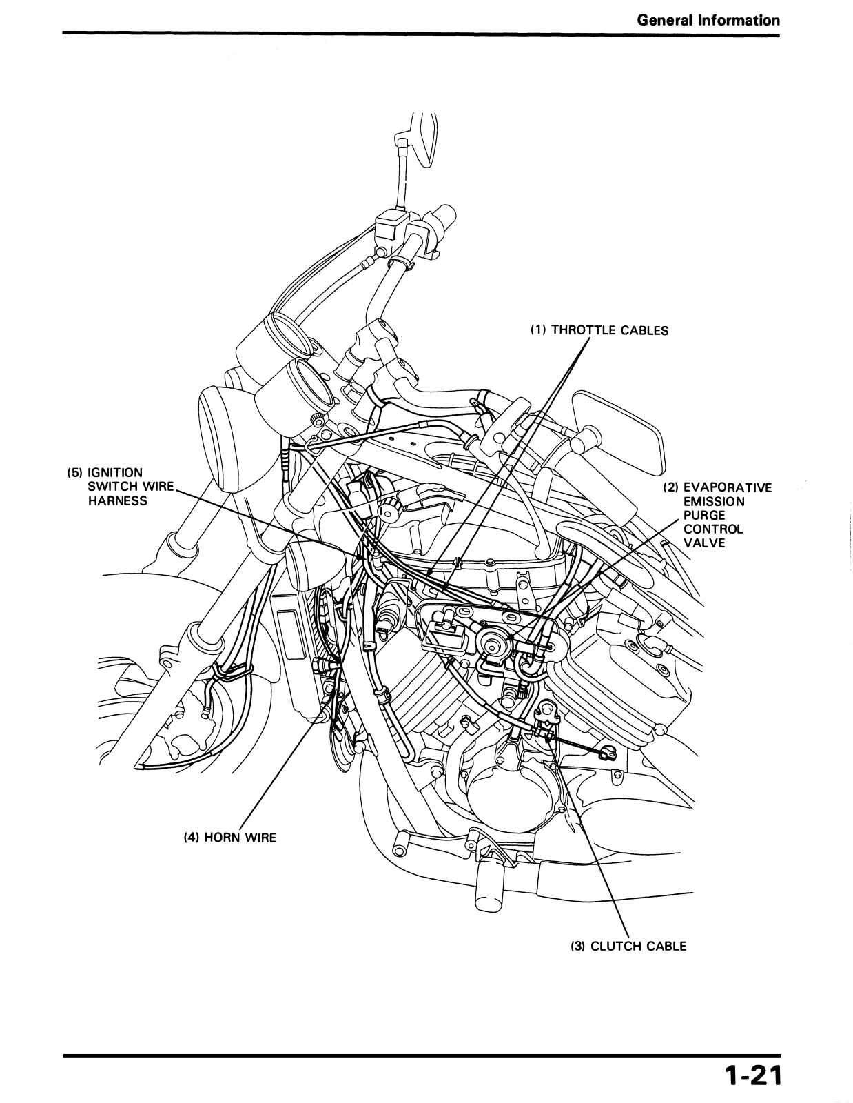
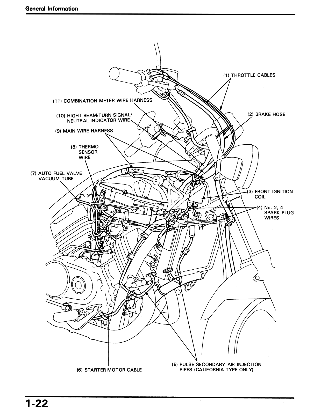
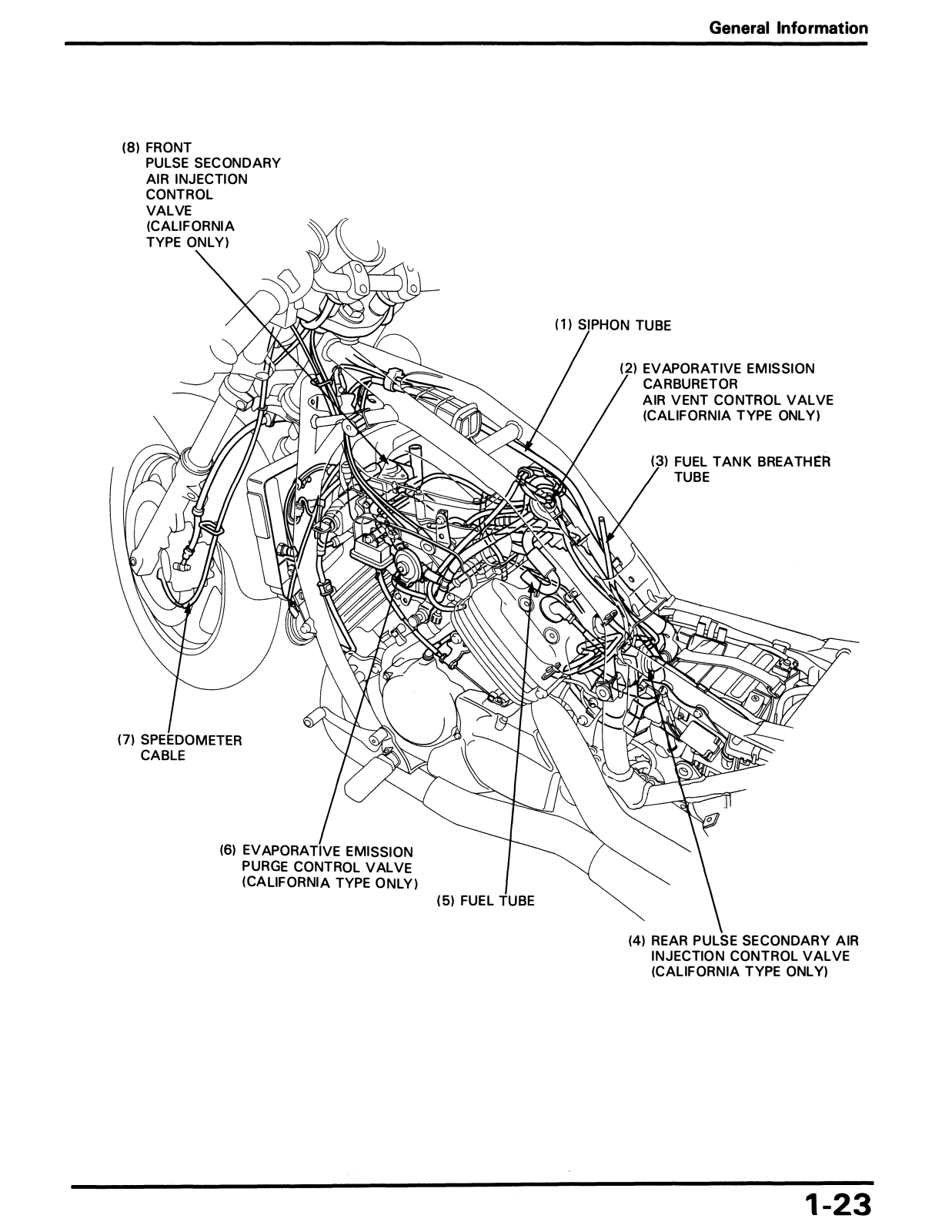
Honda VF 750 C 1994 2003, VF 750 CD 1994 2003 Service manual
...
Honda Service manual
Download
Specifications and Main Features
Frequently Asked Questions
User Manual
Download
Loading...
+
276
hidden pages
Unhide
You need points to download manuals.
1 point = 1 manual.
You can buy points or you can get point for every manual you upload.
Buy points
Upload your manuals
 Loading...