

Page 1
2000
-
06 RESTRAINTS
2006 Honda Insight
2006 Honda Insight
2000-06 RESTRAINTS SRS (Supplemental Restraint System) - Insight
2000-06 RESTRAINTS SRS (Supplemental Restraint System) - Insight
SRS (Supplemental Restraint System) - Insight
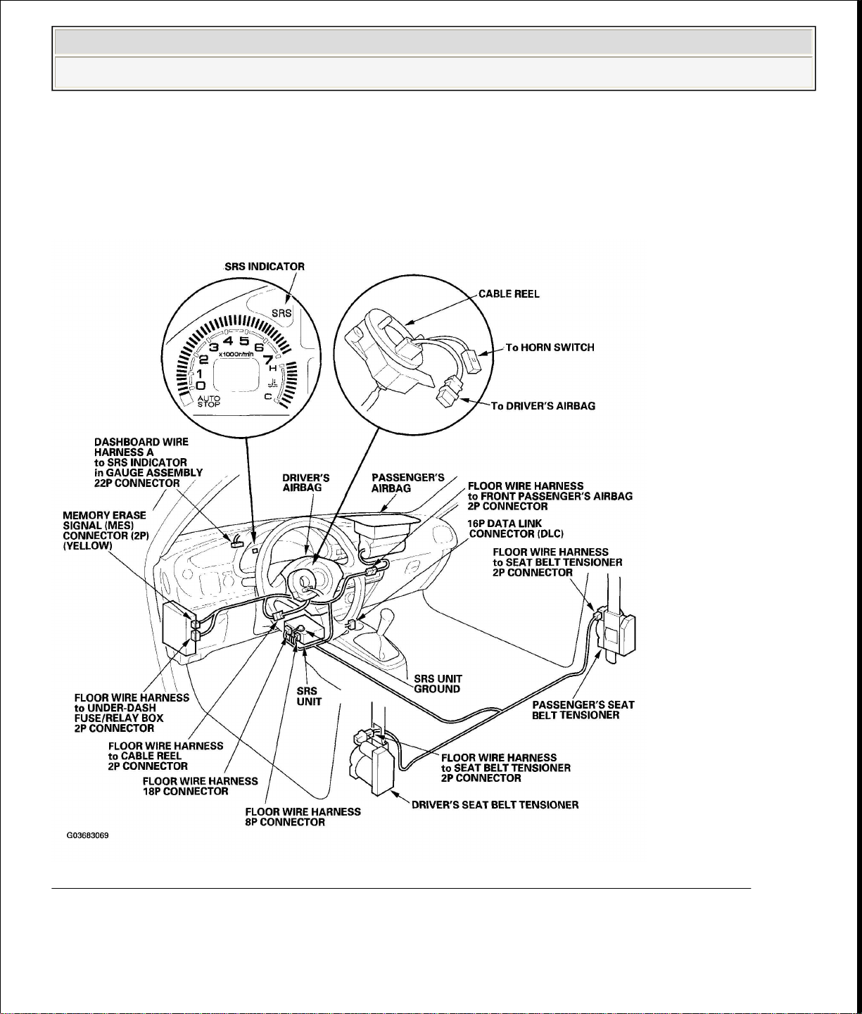
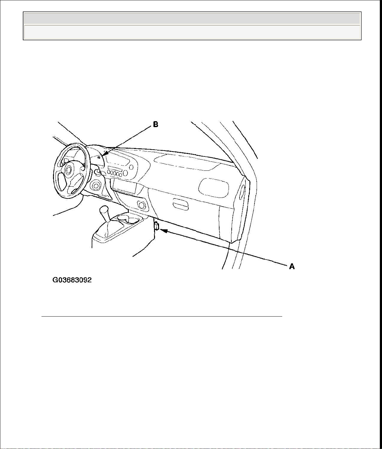
COMPONENT LOCATION INDEX
Fig. 1: Identifying Supplemental Restraint System Components Location
Courtesy of AMERICAN HONDA MOTOR CO., INC.
PRECAUTIONS AND PROCEDURES
GENERAL PRECAUTIONS
Page 2

Please read the following precautions carefully before performing the airbag system
Carefully inspect any SRS part before you install it. Do not install any part that
deformation.
2006 Honda Insight
2000-06 RESTRAINTS SRS (Supplemental Restraint System) - Insight
service. Observe the instructions described in this manual, or the airbags could
accidentally deploy and cause damage or injuries.
Except when performing electrical inspections, always turn the ignition switch
OFF and disconnect the negative cable from the battery, and wait at least 3
minutes before beginning work.
NOTE: The SRS unit memory is not erased even if the ignition
switch is turned OFF or the battery cables are
disconnected from the battery.
Use the replacement parts which are manufactured to the same standards and
quality as the original parts. Do not install used SRS parts. Use only new parts
when making SRS repairs.
shows signs of being dropped or improperly handled, such as dents, cracks or
Page 3
at least three segments. Reinstall the No. 15 EPS (40 A) fuse.
2006 Honda Insight
2000-06 RESTRAINTS SRS (Supplemental Restraint System) - Insight
Fig. 2: Precaution While Handling SRS Parts
Courtesy of AMERICAN HONDA MOTOR CO., INC.
Before removing any of the SRS parts (including disconnection of the
connectors), always disconnect the airbag and seat belt tensioner connectors.
Use only a digital multimeter to check the system. If it is not a Honda
multimeter, make sure its output is 10 mA (0.01 A) or less when switched to
the lowest value in the ohmmeter range. A tester with a higher output could
cause accidental deployment and possible injury.
Do not put objects on the passenger's airbag.
After reconnecting the battery negative cable, if the IMA battery level gauge
(BAT) displays no segments; remove the No. 15 EPS (40 A) fuse from the
under-hood fuse/relay box, then start the engine, and hold it between 3,500
RPM and 4,000 RPM without load (in park or neutral) until the BAT displays
Page 4

STEERING
-
RELATED PRECAUTIONS
precautions.
removed airbag.
2006 Honda Insight
2000-06 RESTRAINTS SRS (Supplemental Restraint System) - Insight
Cable Reel Alignment
Misalignment of the cable reel could cause an open in the wiring, making the
SRS system and the horns inoperative. Center the cable reel whenever the
following is performed (see step 6 ).
Installation of the steering wheel
Installation of the cable reel
Installation of the steering column
Other steering-related adjustment or installation
Do not disassemble the cable reel.
Do not apply grease on the cable reel.
If the cable reel shows any signs of damage or contamination, replace it with a
new one. For example, if it does not rotate smoothly, replace the cable reel.
AIRBAG HANDLING AND STORAGE
Do not disassemble an airbag. It has no serviceable parts. Once an airbag has been
deployed, it cannot be repaired or reused.
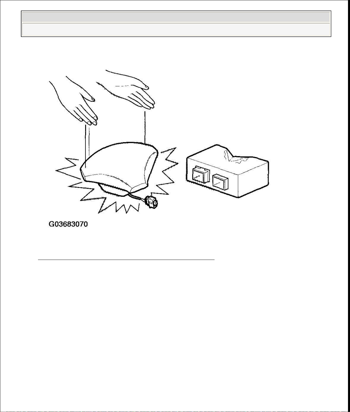
For temporary storage of the airbag during service, please observe the following
Store the removed airbag with the pad surface up. Never put any things on the
Page 5
or water.
2006 Honda Insight
2000-06 RESTRAINTS SRS (Supplemental Restraint System) - Insight
Fig. 3: Storing Removed Airbag With Pad Surface Up
Courtesy of AMERICAN HONDA MOTOR CO., INC.
To prevent damage to the airbag, keep it away from any oil, grease, detergent,
Page 6

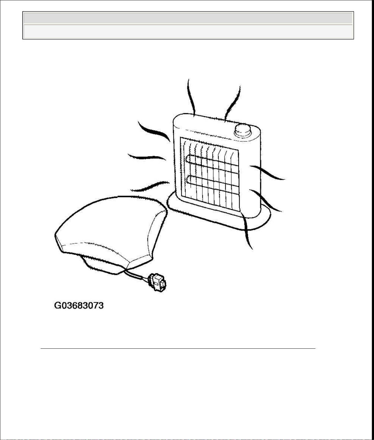
source (exceeding 200°F)
2006 Honda Insight
2000-06 RESTRAINTS SRS (Supplemental Restraint System) - Insight
Fig. 4: Precaution For Preventing Damage Of Airbag From Any Oil,
Grease, Detergent And Water
Courtesy of AMERICAN HONDA MOTOR CO., INC.
Store the removed airbag on a secure, flat surface away from any high heat
Page 7
replacement.
2006 Honda Insight
2000-06 RESTRAINTS SRS (Supplemental Restraint System) - Insight
Fig. 5: Precaution For Preventing Airbag From High Heat Source
Courtesy of AMERICAN HONDA MOTOR CO., INC.
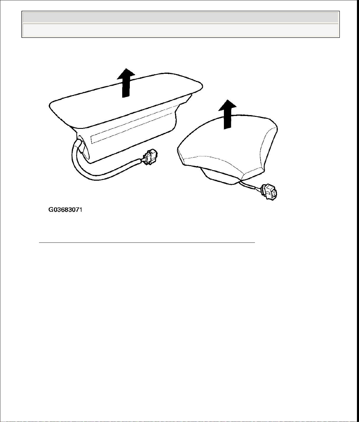
Never perform electrical inspections to the airbags, such as measuring
resistance.
Do not position yourself in front of the airbag during removal, inspection, or
Page 8
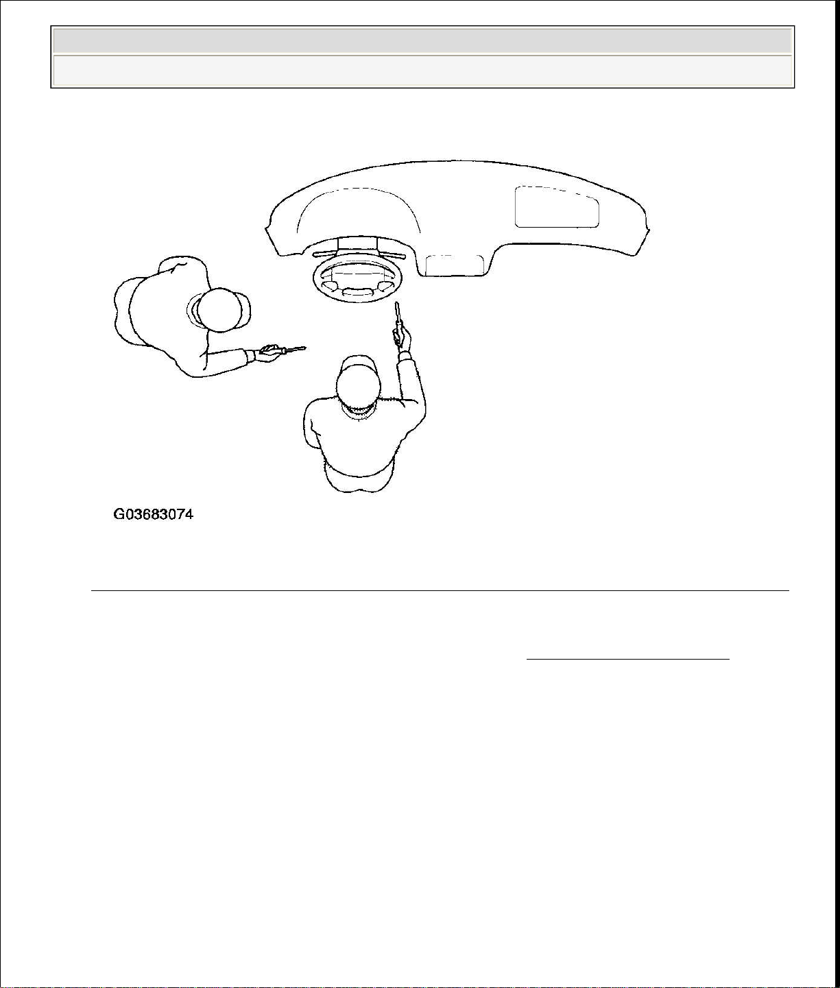
deploy and cause damage or injury.
2006 Honda Insight
2000-06 RESTRAINTS SRS (Supplemental Restraint System) - Insight
Fig. 6: Precaution During Removal, Inspection Or Replacement Of Airbag
Courtesy of AMERICAN HONDA MOTOR CO., INC.
For proper disposal of a damaged airbag, refer to AIRBAG DISPOSAL (see ).
SRS UNIT PRECAUTIONS
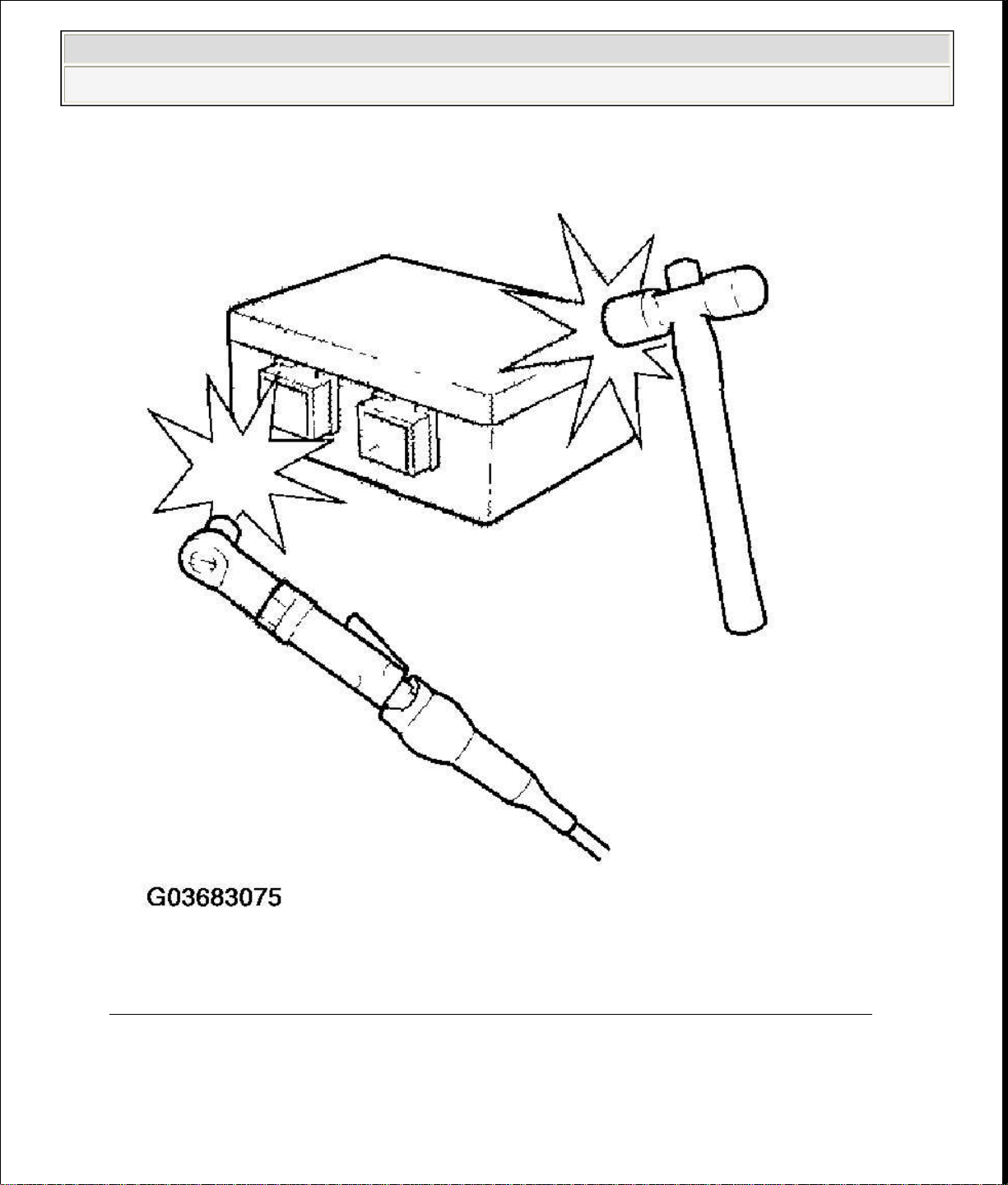
Be careful not to bump or impact the SRS unit whenever the ignition switch is
ON (II), or for at least 3 minutes after the ignition switch is turned OFF.
During installation or replacement, be careful not to bump (by impact wrench,
hammer, etc.) the area around the SRS unit. The airbags could accidentally
Page 9
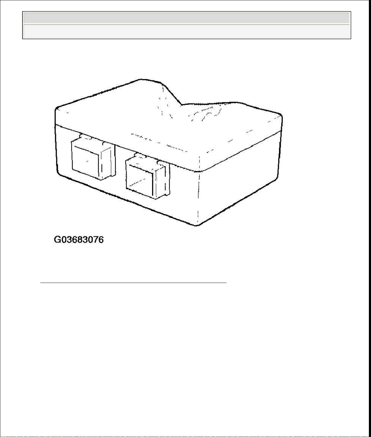
damage or any deformation on the SRS unit. If there is any damage, replace the
SRS unit.
2006 Honda Insight
2000-06 RESTRAINTS SRS (Supplemental Restraint System) - Insight
Fig. 7: Precaution During Installation Or Replacement Of SRS Unit
Courtesy of AMERICAN HONDA MOTOR CO., INC.
After a collision in which the airbags were deployed, replace the SRS unit.
After a collision in which the airbags were not deployed, inspect for any
Page 10
Turn the ignition switch OFF, disconnect the battery negative cable and wait at
WIRING PRECAUTIONS
2006 Honda Insight
2000-06 RESTRAINTS SRS (Supplemental Restraint System) - Insight
Fig. 8: Identifying Deformation On SRS Unit
Courtesy of AMERICAN HONDA MOTOR CO., INC.
Do not disassemble the SRS unit.
least 3 minutes before beginning installation or replacement of the SRS unit,
and disconnection of the 18P connector.
Be sure the SRS unit is installed securely with the mounting bolts torqued to
9.8 N.m (1.0 kgf.m, 7.2 lbf.ft).
Do not spill water or oil on the SRS unit, and keep it away from dust.
Store the SRS unit in a cool (less than 104 °F/40 °C) and dry (less than 80%
relative humidity, no moisture) area.
Page 11
with other parts.
2006 Honda Insight
2000-06 RESTRAINTS SRS (Supplemental Restraint System) - Insight
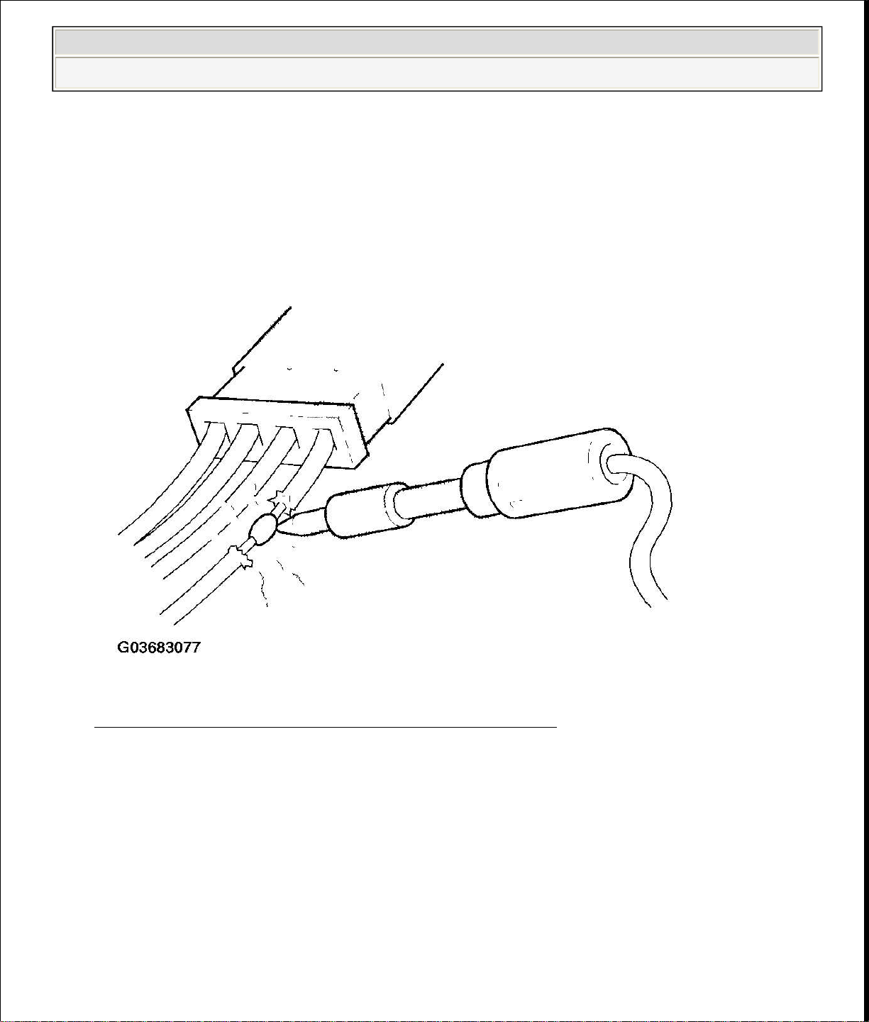
SRS wiring can be identified by a special yellow outer covering, and the SRS
connectors can be identified by their yellow color. Observe the instructions.
Never attempt to modify, splice, or repair SRS wiring. If there is an open or
damage in SRS wiring, replace the harness.
Fig. 9: Precaution While Repairing SRS Wiring
Courtesy of AMERICAN HONDA MOTOR CO., INC.
Be sure to install the harness wires so that they are not pinched or interfering
Page 12

When using electrical test equipment, insert the probe of the tester into the wire
side of the connector. Do not insert the probe of the tester into the terminal side
of the connector, and do not tamper with the connector.
2006 Honda Insight
2000-06 RESTRAINTS SRS (Supplemental Restraint System) - Insight
Fig. 10: Precaution While Installing Harness Wires
Courtesy of AMERICAN HONDA MOTOR CO., INC.
Make sure all SRS ground locations are clean, and grounds are securely
fastened for optimum metal-to-metal contact. Poor grounding can cause
intermittent problems that are difficult to diagnose.
PRECAUTIONS FOR ELECTRICAL INSPECTIONS
Page 13
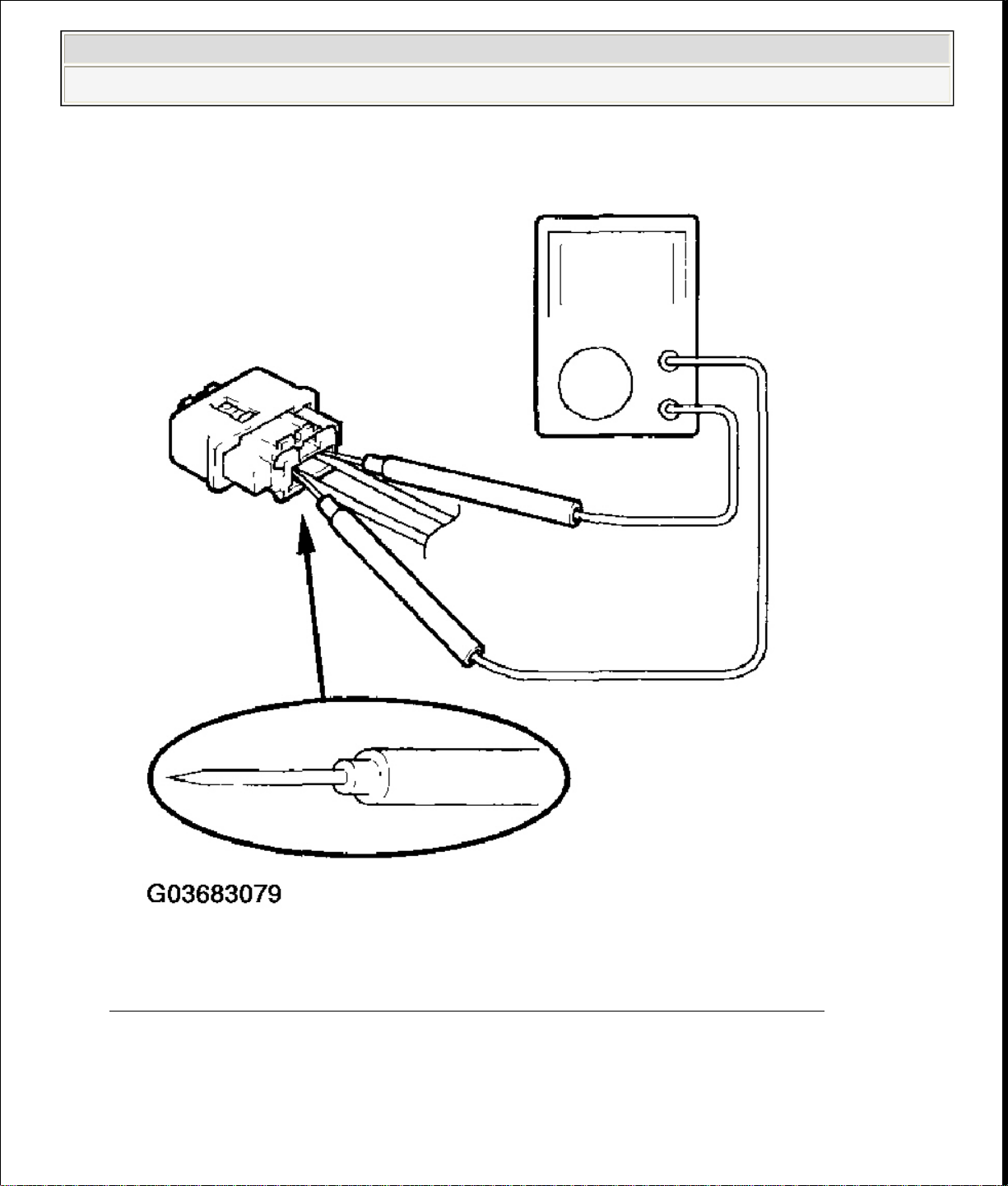
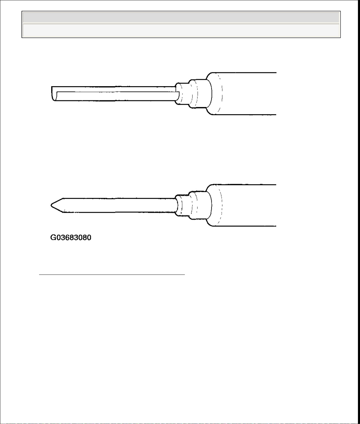
Use a U
-
shaped probe. Do not insert the probe forcibly.
2006 Honda Insight
2000-06 RESTRAINTS SRS (Supplemental Restraint System) - Insight
Fig. 11: Inserting Probe Of Tester Into Wire Side Of Connector
Courtesy of AMERICAN HONDA MOTOR CO., INC.
Page 14
loaded sleeve (A) toward the stop (B) while
apart. Be sure to pull on the sleeve and not on the connector.
2006 Honda Insight
2000-06 RESTRAINTS SRS (Supplemental Restraint System) - Insight
Fig. 12: Identifying U-Shaped Probe
Courtesy of AMERICAN HONDA MOTOR CO., INC.
Use specified service connectors in troubleshooting. Using improper tools
could cause an error in inspection due to poor metal-to-metal contact.
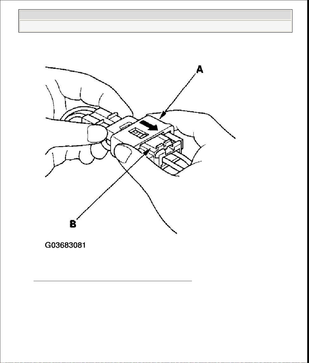
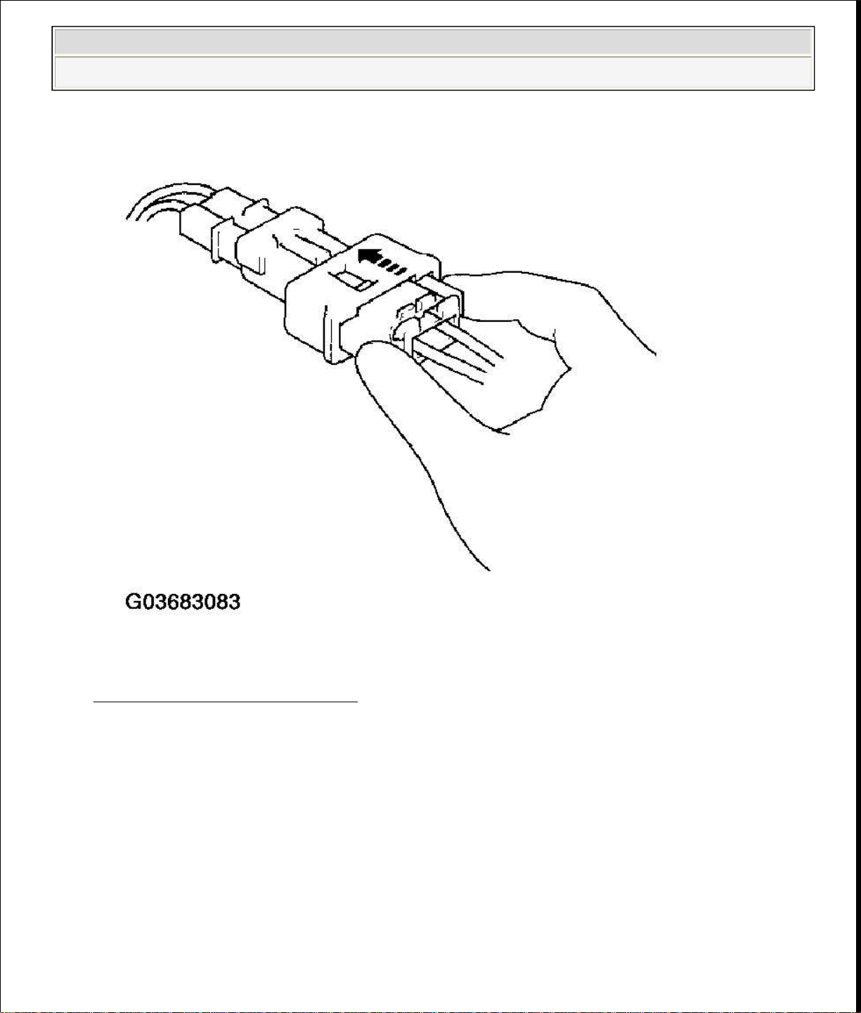
SPRING-LOADED LOCK CONNECTOR
Some SRS system connectors have a spring-loaded lock.
Disconnecting
1. To release the lock, pull the springholding the opposite half of the connector. Then pull the connector halves
Page 15
the sleeve.
2006 Honda Insight
2000-06 RESTRAINTS SRS (Supplemental Restraint System) - Insight
Connecting
Fig. 13: Disconnecting SRS System Connector
Courtesy of AMERICAN HONDA MOTOR CO., INC.
2. To reconnect, hold the pawl-side connector, and press on the back of the
sleeve-side connector half in the direction shown. As the two connector halves
are pressed together, the sleeve (A) is pushed back by the pawl. Do not touch
Page 16
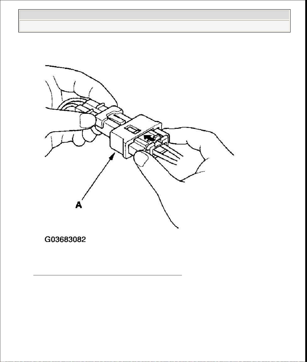
the spring
-
loaded sleeve locks the connector.
2006 Honda Insight
2000-06 RESTRAINTS SRS (Supplemental Restraint System) - Insight
Fig. 14: Connecting SRS System Connector
Courtesy of AMERICAN HONDA MOTOR CO., INC.
When the connector halves are completely connected, the pawl is released, and
Page 17
2006 Honda Insight
2000-06 RESTRAINTS SRS (Supplemental Restraint System) - Insight
Fig. 15: Locking Connector
Courtesy of AMERICAN HONDA MOTOR CO., INC.
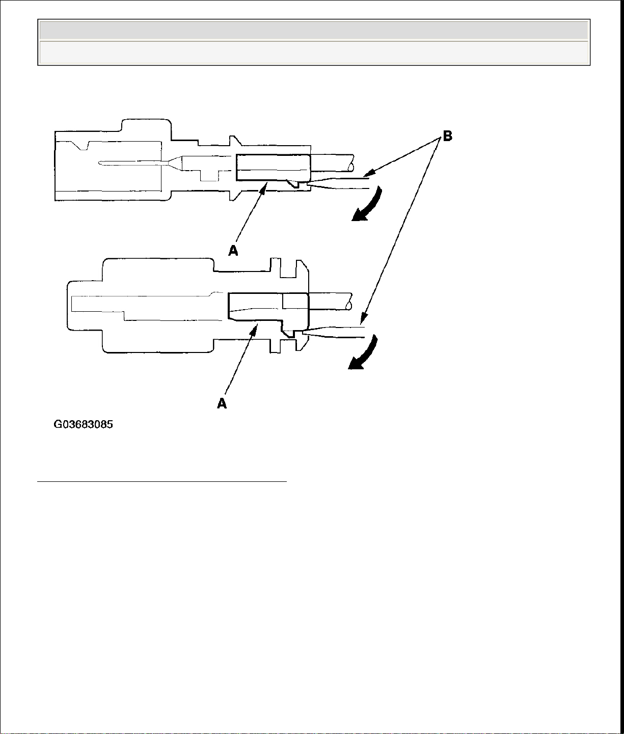
BACKPROBING SPRING-LOADED LOCK CONNECTORS
When checking voltage or resistance on this type of connector the first time, you
must remove the retainer (A) to insert the tester probe from the wire side.
NOTE: It is not necessary to reinstall the removed retainer; the
terminals will stay locked in the connector housing.
Page 18

connector.
2006 Honda Insight
2000-06 RESTRAINTS SRS (Supplemental Restraint System) - Insight
Fig. 16: Removing Retainer (1 Of 2)
Courtesy of AMERICAN HONDA MOTOR CO., INC.
To remove the retainer (A), insert a flat-tip screwdriver (B) between the connector
body and the retainer, then carefully pry out the retainer. Take care not to break the
Page 19
Before removing the airbag or SRS related devices (the SRS unit, the cable reel and
connectors (E, F).
2006 Honda Insight
2000-06 RESTRAINTS SRS (Supplemental Restraint System) - Insight
Fig. 17: Removing Retainer (2 Of 2)
Courtesy of AMERICAN HONDA MOTOR CO., INC.
DISCONNECTING SYSTEM CONNECTORS
the seat belt tensioner connector), disconnecting connectors from SRS related
devices, or removing the dashboard or the steering column, disconnect the airbag
connectors and seat belt tensioner connectors to prevent accidental deployment.
Turn the ignition switch OFF, disconnect the negative cable from the battery, and
wait at least 3 minutes before beginning the following procedures.
Before disconnecting the SRS unit connector A (18P) (A) from the SRS unit,
disconnect both airbag 2P connectors (C, D) and both seat belt tensioner 2P
Page 20
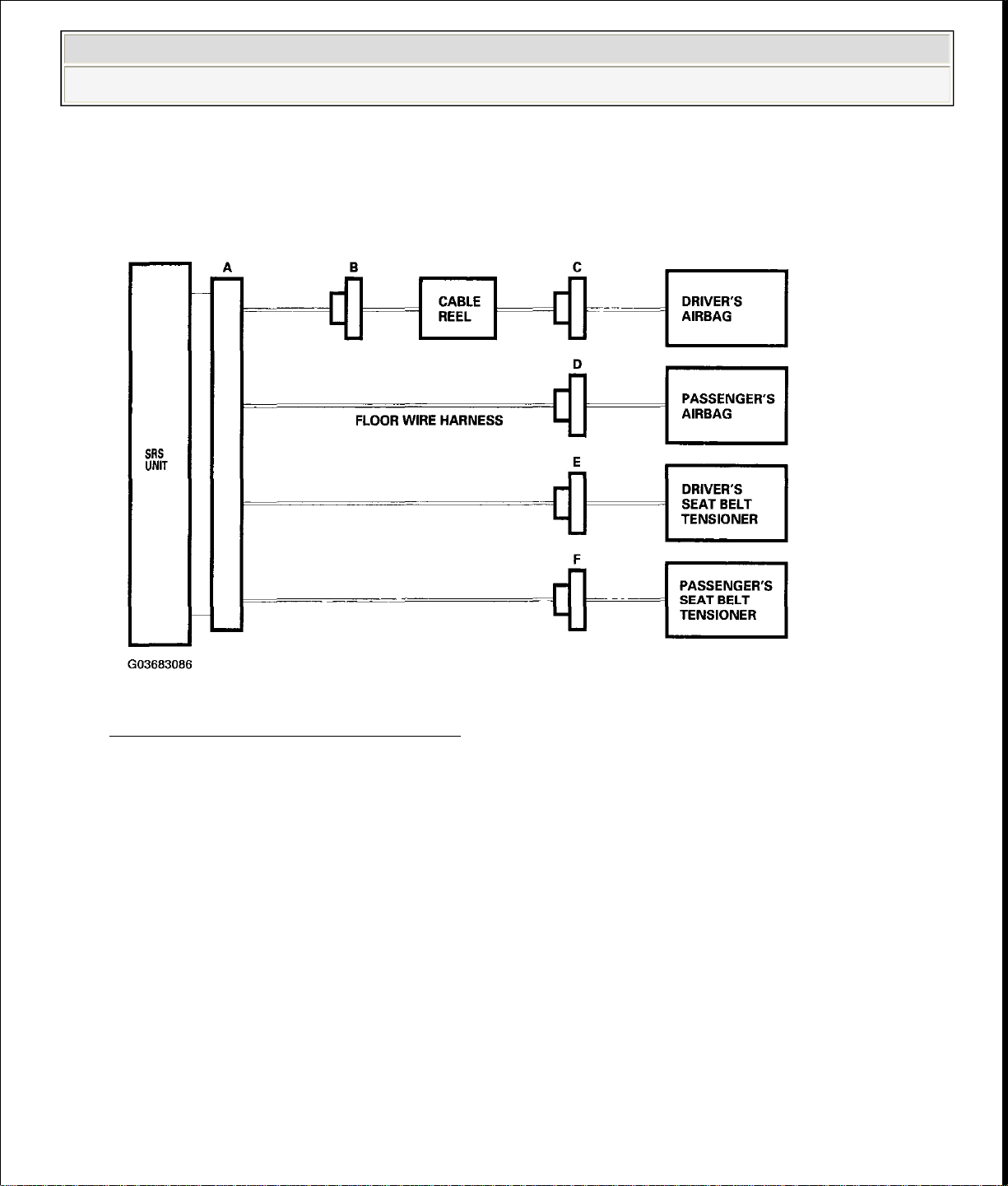
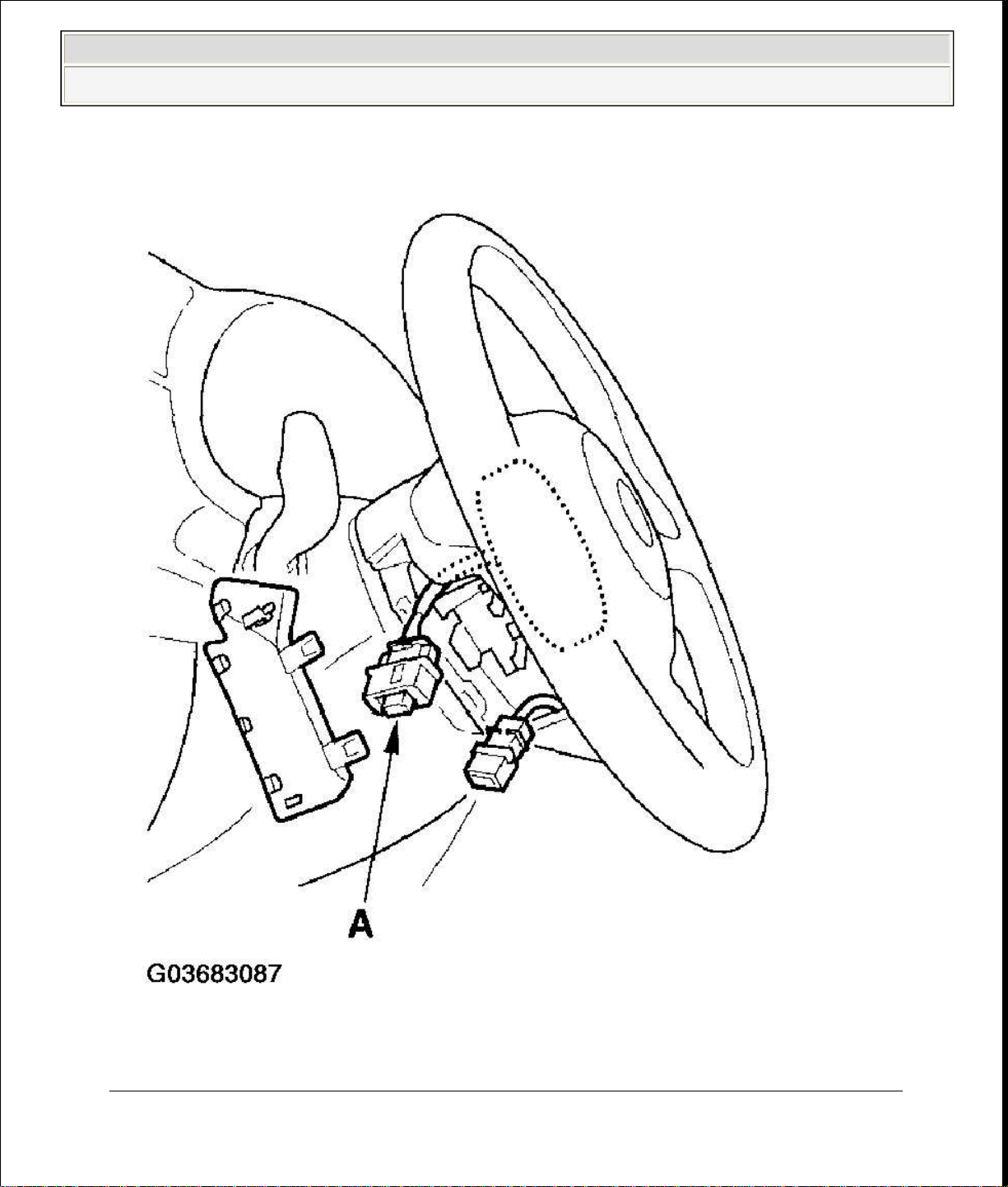
driver's airbag 2P connector (A) from the cable reel.
2006 Honda Insight
2000-06 RESTRAINTS SRS (Supplemental Restraint System) - Insight
Before disconnecting the cable reel 2P connector (B), disconnect the driver's
airbag 2P connector (C).
Fig. 18: Identifying Connectors
Courtesy of AMERICAN HONDA MOTOR CO., INC.
1. Turn the ignition switch OFF. Disconnect the battery negative cable, and wait
at least 3 minutes.
Driver's Airbag
2. Remove the access panel from the steering wheel, then disconnect the
Page 21
2006 Honda Insight
2000-06 RESTRAINTS SRS (Supplemental Restraint System) - Insight
Fig. 19: Disconnecting Driver's Airbag 2P Connector From Cable Reel
Courtesy of AMERICAN HONDA MOTOR CO., INC.
Passenger's Airbag
Page 22
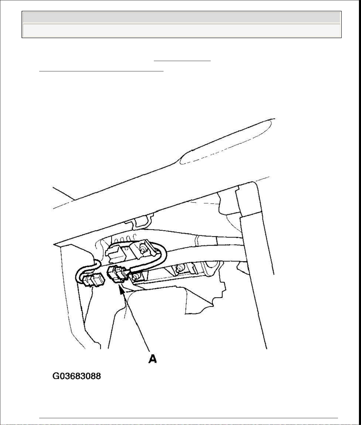
Fig. 20: Disconnecting Passenger's Airbag 2P Connector From Floor Wire
2006 Honda Insight
2000-06 RESTRAINTS SRS (Supplemental Restraint System) - Insight
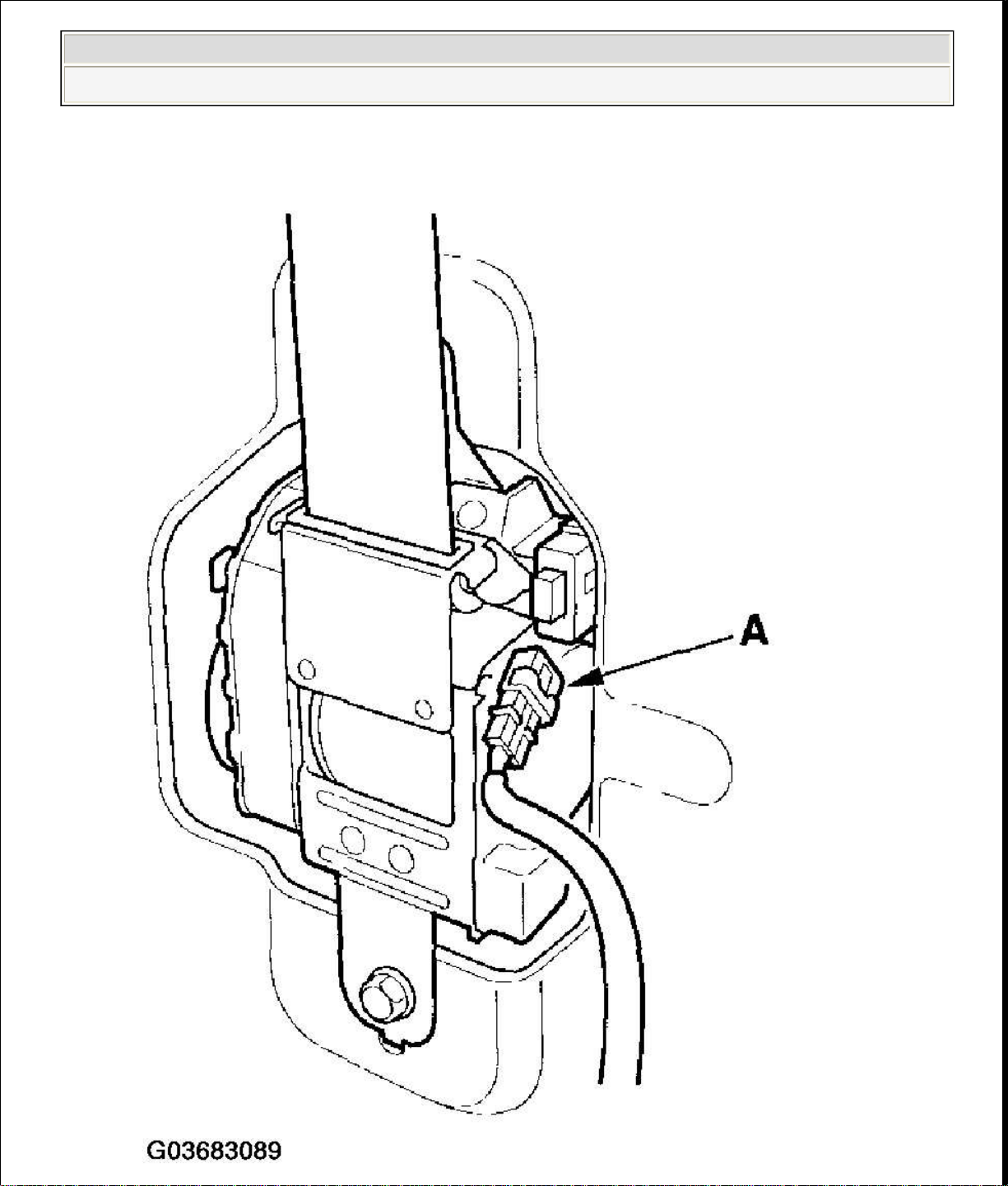
3. Remove the glove box (see GLOVE BOX
REMOVAL/INSTALLATION ), then disconnect the passenger's airbag 2P
connector (A) from the floor wire harness.
Page 23

Harness
), then disconnect the floor
wire harness 2P connector (A) from the seat belt tensioner.
2006 Honda Insight
2000-06 RESTRAINTS SRS (Supplemental Restraint System) - Insight
Courtesy of AMERICAN HONDA MOTOR CO., INC.
Seat Belt Tensioner
4. Remove the B-pillar lower trim panel (see TRIM
REMOVAL/INSTALLATION - DOOR AREAS
Page 24
2006 Honda Insight
2000-06 RESTRAINTS SRS (Supplemental Restraint System) - Insight
Page 25
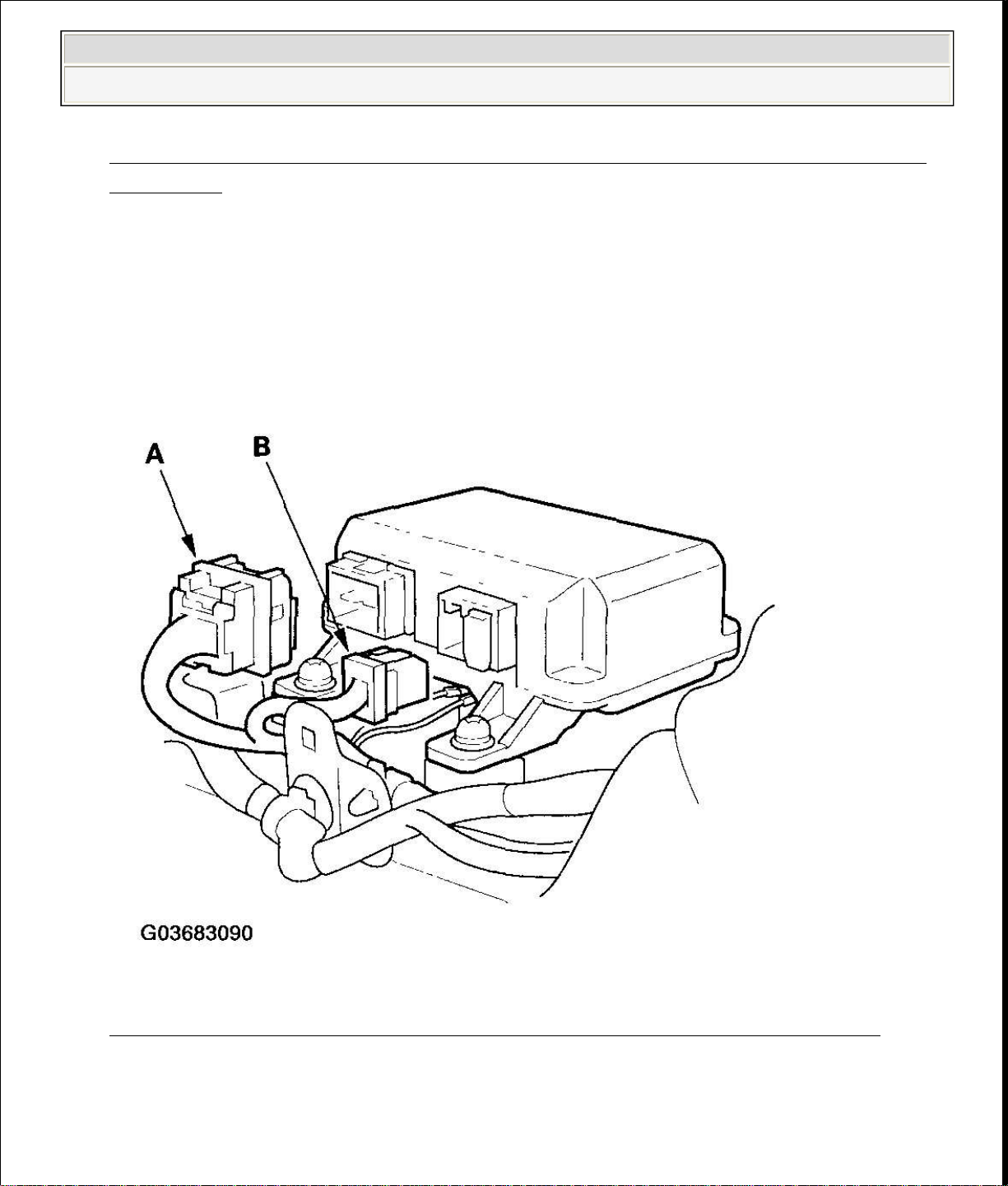
Fig. 21: Disconnecting Floor Wire Harness 2P Connector From Seat Belt
DTC (DIAGNOSTIC TROUBLE CODES)
2006 Honda Insight
2000-06 RESTRAINTS SRS (Supplemental Restraint System) - Insight
Tensioner
Courtesy of AMERICAN HONDA MOTOR CO., INC.
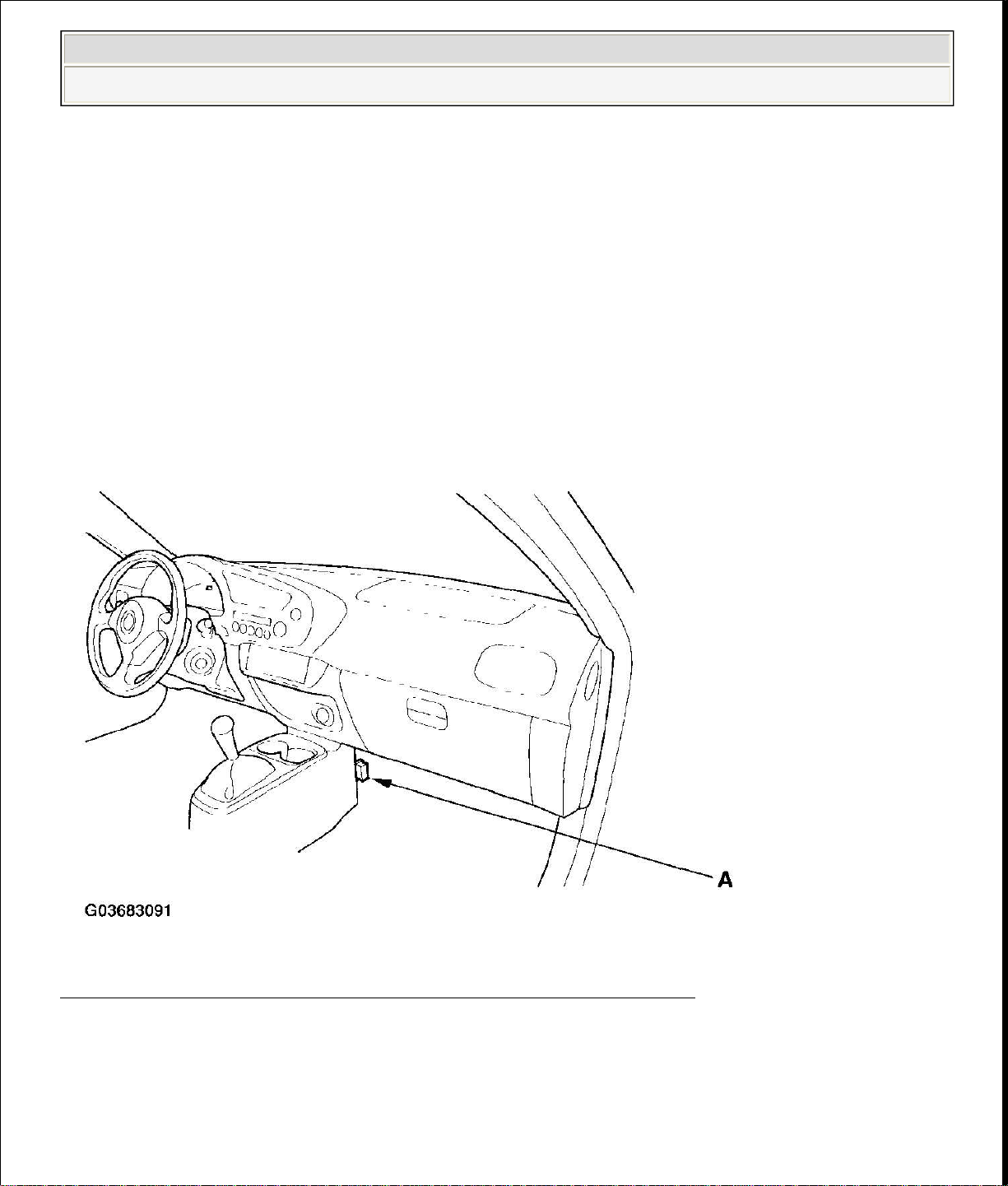
SRS Unit
5. Disconnect SRS unit connector A and/or SRS unit connector B from the
SRS unit.
Fig. 22: Disconnecting SRS Unit Connector A And B From SRS Unit
Courtesy of AMERICAN HONDA MOTOR CO., INC.
GENERAL TROUBLESHOOTING INFORMATION
Page 26

Whenever the ignition switch is ON (II), or has been turned OFF for less than 3
backprobe set and the multimeter. Backprobe spring
-
loaded lock type
2006 Honda Insight
2000-06 RESTRAINTS SRS (Supplemental Restraint System) - Insight
The self-diagnostic function of the SRS system allows it to locate the causes of
system problems and then store this information in memory. For easier
troubleshooting, this data can be retrieved via a data link circuit.
When you turn the ignition switch ON (II), the SRS indicator will come on. If
it goes off after 6 seconds, the system is normal.
If there is an abnormality, the system locates and defines the problem, stores
this information in memory, and turns the SRS indicator on. The data will
remain in the memory even when the ignition switch is turned off or if the
battery is disconnected.
When you connect the HDS to the 16P data link connector (DLC) to short the
SCS terminal, and turn the ignition switch ON (II), the SRS indicator will
indicate the diagnostic trouble code (DTC) by the number of blinks.
When you connect the HDS to the 16P data link connector (DLC), you can
retrieve the DTC in the "SRS" menu in the HDS.
After reading and recording the DTC, proceed with the troubleshooting
procedure for the code indicated.
Precautions
Use only a digital multimeter to check the system. If it is not a Honda
multimeter, make sure its output is 10 mA (0.01 A) or less when switched to
the smallest value in the ohmmeter range. A tester with a higher output could
damage the airbag circuit or cause accidental airbag deployment and possible
injury.
minutes, be careful not to bump the SRS unit; the airbags could accidentally
deploy and cause damage or injuries.
Before you remove the SRS harness, disconnect the driver's airbag connector,
the passenger's airbag connector and seat belt tensioner connectors.
Make sure the battery is sufficiently charged. If the battery is dead or low, the
measuring values may not be correct.
Do not touch a tester probe to the terminals in the SRS unit or harness
connectors, and do not connect the terminals with a jumper wire. Use only the
Page 27
prompts in the "SRS" menu. If the tester indicates no DTC, DTC 9
connected to the 16P data link connector (DLC), and the SCS line is grounded.
2006 Honda Insight
2000-06 RESTRAINTS SRS (Supplemental Restraint System) - Insight
connectors correctly.
READING THE DTC
When the SRS indicator is on, read the DTC using either of the following methods:
HDS "SRS" Menu Method
Connect the HDS to the 16P data link connector (DLC) (A), and follow the HDS
-1 or DTC 9-2,
double-check by using the "SCS" menu method (see HDS SCS Menu Method).
Fig. 23: Identifying Data Link Connector (DLC) (1 Of 2)
Courtesy of AMERICAN HONDA MOTOR CO., INC.
HDS "SCS" Menu Method (retrieving flash codes)
The SRS indicator indicates the DTC by the number of blinks when the HDS is
Page 28
SRS indicator (B) should come on for about 6 seconds, and then go off. Then it
In case of an intermittent failure, the SRS indicator will indicate the DTC
2006 Honda Insight
2000-06 RESTRAINTS SRS (Supplemental Restraint System) - Insight
1. Make sure the ignition switch is OFF.
2. Connect the HDS to the 16P data link connector (DLC) (A), and follow the
HDS prompts in the "SCS" menu to ground the SCS line.
Fig. 24: Identifying Data Link Connector (DLC) (2 Of 2)
Courtesy of AMERICAN HONDA MOTOR CO., INC.
3. Make sure the SCS line is grounded, then turn the ignition switch ON (II). The
will blink to indicate DTCs (see the table).
The DTC consists of a main code and a sub code.
Including the most recent problem, up to three different DTCs can be
indicated.
In case of a continuous failure, the DTC will be indicated repeatedly (see
example 1).
Page 29
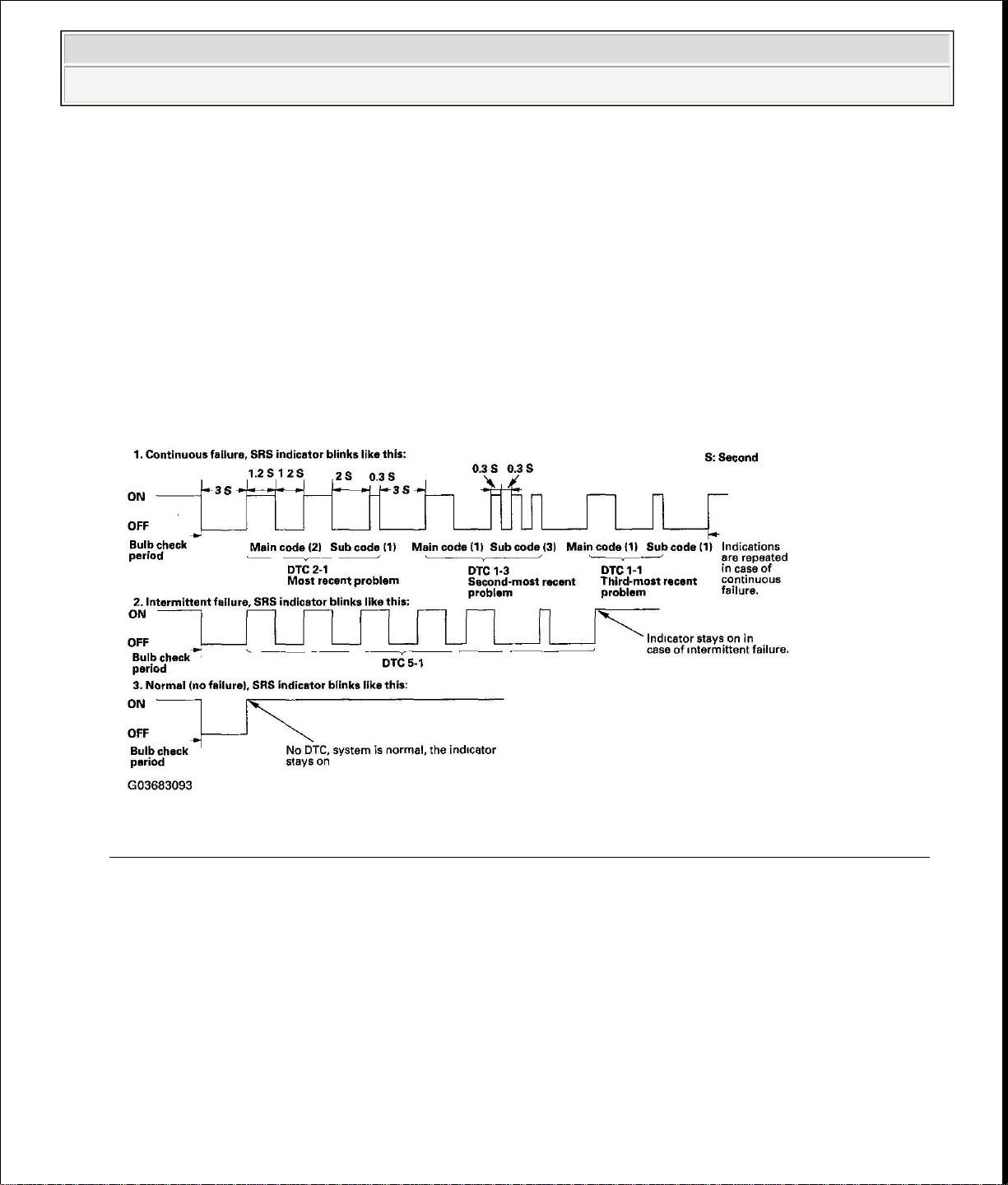
In case the system is normal (no DTC), the SRS indicator will stay on (see
Special Tools Required
2006 Honda Insight
2000-06 RESTRAINTS SRS (Supplemental Restraint System) - Insight
one time, then it will stay on (see example 2).
If a continuous and an intermittent failure occur, both DTCs will be
indicated as continuous failures.
example 3).
If the SRS indicator does not come on as indicated above, always check
for an open or a short to ground in the SCS circuit before troubleshooting
the system.
Fig. 25: Identifying SRS Indicator Blinking Pattern (Continuous Failure)
Courtesy of AMERICAN HONDA MOTOR CO., INC.
4. Read the DTC.
5. Turn the ignition switch OFF, and wait for 10 seconds.
6. Disconnect the HDS from the 16P data link connector (DLC).
7. Proceed with the troubleshooting procedure for the DTC.
ERASING THE DTC MEMORY
Page 30
3.
Turn the ignition switch ON (II).
2006 Honda Insight
2000-06 RESTRAINTS SRS (Supplemental Restraint System) - Insight
SCS service connector 07PAZ-0010100
To erase the DTC(s) from the SRS unit, use the HDS or follow this procedure.
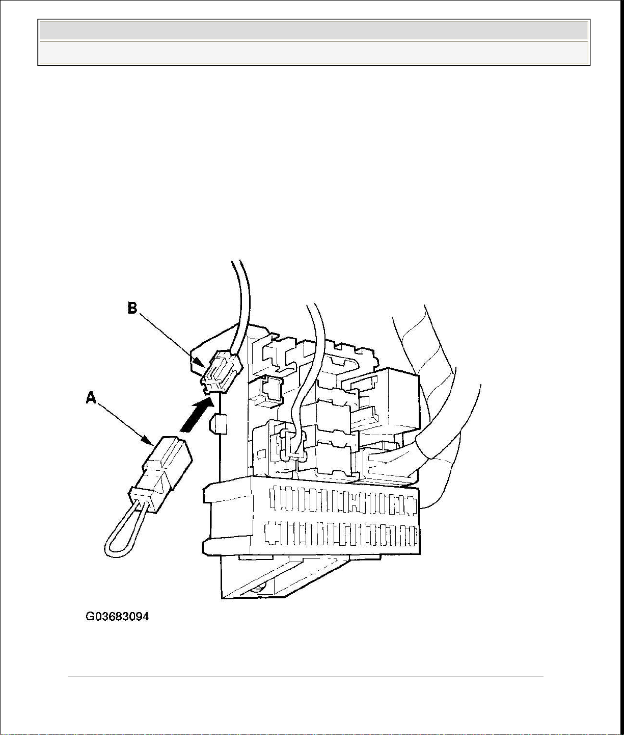
1. Make sure the ignition switch is OFF.
2. Connect the SCS service connector (A) to the MES connector (2P) (B). Do not
use a jumper wire.
Fig. 26: Connecting SCS Service Connector To MES Connector (2P)
Courtesy of AMERICAN HONDA MOTOR CO., INC.
Page 31

the SCS service connector from the MES connector (2P) within 4 seconds after
The SRS indicator will come on again. Reconnect the SCS service connector to
7.
If you cannot duplicate the intermittent failure, the system is OK at this time.
2006 Honda Insight
2000-06 RESTRAINTS SRS (Supplemental Restraint System) - Insight
4. The SRS indicator comes on for about 6 seconds, and then goes off. Remove
the indicator goes off.
5.
the MES connector (2P) within 4 seconds after the indicator comes on.
6. When the SRS indicator goes off, remove the SCS service connector from the
MES connector (2P) within 4 seconds.
7. The SRS indicator blinks two times, indicating that the memory has been
erased.
8. Turn the ignition switch OFF, and wait for 10 seconds.
9. Turn the ignition switch ON (II) again. If the SRS indicator comes on for 6
seconds and then goes off, the system is OK.
TROUBLESHOOTING INTERMITTENT FAILURES
If there was a malfunction, but it does not recur, it will be stored in the memory as
an intermittent failure, and the SRS indicator will come on.
After checking the DTC, troubleshoot as follows:
1. Read the DTC (see "READING THE DTC ").
2. Erase the DTC memory (see "ERASING THE DTC MEMORY ").
3. With the shift lever in neutral, start the engine, and let the engine idle.
4. The SRS indicator comes on for about 6 seconds and then goes off.
5. Shake the related wire harness and connectors, and look for loose connections,
pin fits, and poor grounds.
6. Take a test-drive (quick acceleration, quick braking, and cornering), turn the
steering wheel fully left and right, and hold it there for 5 to 10 seconds. If the
problem recurs, the SRS indicator will come on.
NOTE: A faulty cable reel can cause intermittent connection
related to the driver's airbag.
Page 32

DTC TROUBLESHOOTING INDEX
1: OPEN IN
DRIVER'S AIRBAG
2:
INCREASED RESISTANCE
IN DRIVER'S AIRBAG
1: OPEN IN
DRIVER'S AIRBAG
2:
INCREASED RESISTANCE
IN DRIVER'S AIRBAG
3: SHORT TO
ANOTHER WIRE OR
DECREASED
RESISTANCE IN
DRIVER'S AIRBAG
4: SHORT TO
POWER IN DRIVER'S
5: SHORT TO
GROUND IN DRIVER'S
1: OPEN IN
PASSENGER'S AIRBAG
2:
INCREASED RESISTANCE
IN PASSENGER'S AIRBAG
1: OPEN IN
2006 Honda Insight
2000-06 RESTRAINTS SRS (Supplemental Restraint System) - Insight
DTC TROUBLESHOOTING INDEX
DTC Detection Item Notes
(see DTC 1-
INFLATOR; DTC 1-
1-1 Open in driver's airbag inflator
INFLATOR )
(see DTC 1-
Increased resistance in driver's airbag
INFLATOR; DTC 1-
1-2
inflator
1-3
Short to another wire or decreased
resistance in driver's airbag inflator
1-4 Short to power in driver's airbag inflator
1-5 Short to ground in driver's airbag inflator
2-1 Open in passenger's airbag inflator
INFLATOR )
(see DTC 1-
INFLATOR )
(see DTC 1-
AIRBAG INFLATOR )
(see DTC 1-
AIRBAG INFLATOR )
(see DTC 2-
INFLATOR; DTC 2-
INFLATOR )
(see DTC 2-
Page 33

Increased resistance in passenger's airbag
PASSENGER'S AIRBAG
2:
INCREASED RESISTANCE
IN PASSENGER'S AIRBAG
3: SHORT TO
ANOTHER WIRE OR
DECREASED
RESISTANCE IN
PASSENGER'S AIRBAG
4: SHORT TO
POWER IN PASSENGER'S
5: SHORT TO
GROUND IN
PASSENGER'S AIRBAG
1: OPEN IN
DRIVER'S SEAT BELT
2:
INCREASED RESISTANCE
IN DRIVER'S SEAT BELT
1: OPEN IN
DRIVER'S SEAT BELT
2:
INCREASED RESISTANCE
IN DRIVER'S SEAT BELT
3: SHORT TO
ANOTHER WIRE OR
DECREASED
RESISTANCE IN
DRIVER'S SEAT BELT
2006 Honda Insight
2-2
2-3
2-4
2000-06 RESTRAINTS SRS (Supplemental Restraint System) - Insight
inflator
Short to another wire or decreased
resistance in passenger's airbag inflator
Short to power in passenger's airbag
inflator
INFLATOR; DTC 2-
INFLATOR )
(see DTC 2-
INFLATOR. )
(see DTC 2-
AIRBAG INFLATOR )
2-5
Short to ground in passenger's airbag
inflator
3-1 Open in driver's seat belt tensioner
Increased resistance in driver's seat belt
3-2
tensioner
(see DTC 2-
INFLATOR )
(see DTC 3-
TENSIONER; DTC 3-
TENSIONER )
(see DTC 3-
TENSIONER; DTC 3-
TENSIONER )
3-3
Short to another wire or decreased
resistance in driver's seat belt tensioner
(see DTC 3-
Page 34

4: SHORT TO
POWER IN DRIVER'S
5: SHORT TO
GROUND IN DRIVER'S
1: OPEN IN
PASSENGER'S SEAT
2: INCREASED
RESISTANCE IN
PASSENGER'S SEAT
1: OPEN IN
PASSENGER'S SEAT
2: INCREASED
RESISTANCE IN
PASSENGER'S SEAT
3: SHORT TO
ANOTHER WIRE OR
DECREASED
RESISTANCE IN
PASSENGER'S SEAT
4: SHORT TO
POWER IN PASSENGER'S
5: SHORT TO
GROUND IN
PASSENGER'S SEAT
2006 Honda Insight
2000-06 RESTRAINTS SRS (Supplemental Restraint System) - Insight
Short to power in driver's seat belt
3-4
tensioner
Short to ground in driver's seat belt
3-5
tensioner
4-1 Open in passenger's seat belt tensioner
TENSIONER )
(see DTC 3-
SEAT BELT TENSIONER )
(see DTC 3-
SEAT BELT TENSIONER )
(see DTC 4-
BELT TENSIONER; DTC 4-
BELT TENSIONER )
4-2
4-3
4-4
(see DTC 4-
BELT TENSIONER; DTC 4-
Increased resistance in passenger's seat
belt tensioner
BELT TENSIONER )
(see DTC 4-
Short to another wire or decreased
resistance in passenger's seat belt
tensioner
BELT TENSIONER )
(see DTC 4-
Short to power in passenger's seat belt
tensioner
SEAT BELT TENSIONER )
4-5
Short to ground in passenger's seat belt
tensioner
(see DTC 4-
BELT TENSIONER )
Page 35

3,
6:
INTERNAL FAILURE OF
intermittent, it could mean internal failure
1: INTERNAL
FAILURE OF THE SRS
2: FAULTY
POWER SUPPLY (VB
2006 Honda Insight
5-1
5-2
5-3
5-4
6-1
6-2
6-3
6-4
7-1
7-2
7-3
8-1
8-2
2000-06 RESTRAINTS SRS (Supplemental Restraint System) - Insight
Internal failure of the SRS unit
NOTE:
Before troubleshooting DTCs 5-1 through 8-6 check
battery/system voltage. If voltage is low, repair the
charging system or replace the battery before
troubleshooting the SRS.
(see DTC 5-1, 5-2, 5-3, 5-4, 6-
1, 6-2, 6-3, 6-4, 7-1, 7-2, 7-
8-1, 8-2, 8-3, 8-4, 8-
THE SRS UNIT )
8-3
8-4
8-6
9-1
Internal failure of the SRS unit. If
of the unit or a faulty indicator light
circuit. Refer to
TROUBLESHOOTING
INTERMITTENT FAILURES (see ).
NOTE:
Before troubleshooting DTC 9-1, check
battery/system voltage. If voltage is low, repair the
charging system or replace the battery before
troubleshooting the SRS.
Internal failure of the SRS unit. If
intermittent, there may be an internal
failure of the power supply (VB line).
(see DTC 9-
UNIT )
(see DTC 9-
9-2
Refer to TROUBLESHOOTING
INTERMITTENT FAILURES (see ).
NOTE:
LINE) )
Page 36

instantly retracts the belt firmly to secure the occupants in their seats.
1: AIRBAGS
AND SEAT BELT
TENSIONERS
does not come
Retrieve the flash codes using
the SCS menu method (see
HDS "SCS" MENU
METHOD (RETRIEVING
2006 Honda Insight
2000-06 RESTRAINTS SRS (Supplemental Restraint System) - Insight
Before troubleshooting DTC 9-2, check
battery/system voltage. If voltage is low, repair the
charging system or replace the battery before
troubleshooting the SRS.
(see DTC 10-
Airbags and seat belt tensioners
10-1
deployed.
DEPLOYED )
SYMPTOM TROUBLESHOOTING INDEX
SYMPTOM TROUBLESHOOTING INDEX
Symptom Diagnostic procedure Also check for
SRS indicator
Symptom Troubleshooting (see
SYMPTOM
on
TROUBLESHOOTING )
SRS indicator
Symptom Troubleshooting (see
stays on, but
SYMPTOM
no DTCs are
TROUBLESHOOTING )
stored
FLASH CODES) ).
SYSTEM DESCRIPTION
SRS COMPONENTS
The SRS is a safety device which, when used in conjunction with the seat belt, is
designed to help protect the driver and passenger in a frontal impact exceeding a
certain set limit. The system consists of the SRS unit, including a safing sensor and
an impact sensor (A), the cable reel (B), the driver's airbag (C) and the passenger's
airbag (D). The seat belt tensioner (E) is linked with the SRS airbags to further
increase the effectiveness of the seat belt. In a front-end collision, the tensioner
Page 37

3.
The inflators must ignite and deploy the airbags and activate the tensioners.
2006 Honda Insight
2000-06 RESTRAINTS SRS (Supplemental Restraint System) - Insight
Fig. 27: Identifying SRS Components
Courtesy of AMERICAN HONDA MOTOR CO., INC.
SRS OPERATION
The main circuit in the SRS unit senses and judges the force of impact and, if
necessary, ignites the inflator charges. If battery voltage is too low or power is
disconnected due to impact, the voltage regulator and the back-up power circuit
respectively will keep voltage at a constant level.
For the SRS to operate
1. The impact sensor must activate and send electronic signals to the
microprocessor.
2. The microprocessor must compute the signals and send them to the airbag
inflators and seat belt tensioners.
Page 38

diagnosis circuit is built into the SRS unit; when the ignition switch is turned
seconds, or if it comes on while driving, it indicates an abnormality in the SRS. The
CIRCUIT DIAGRAM
2006 Honda Insight
2000-06 RESTRAINTS SRS (Supplemental Restraint System) - Insight
Fig. 28: Circuit Schematic - SRS Unit
Courtesy of AMERICAN HONDA MOTOR CO., INC.
Self-diagnosis System
A selfON (II), the SRS indicator comes on and goes off after about 6 seconds, if the SRS
is operating normally. If the indicator does not come on, or does not go off after 6
SRS must be inspected and repaired as soon as possible. For better serviceability,
the memory will store the cause of the malfunction, and the data link circuit passes
on information from memory to the 16P data link connector (DLC). This
information can be read with the HDS connected to the 16P data link connector
(DLC) (see GENERAL TROUBLESHOOTING INFORMATION ).
NOTE: Before you disconnect the battery negative cable, make
sure you have the anti-theft code for the radio, and then
write the audio presets.
Page 39

2006 Honda Insight
2000-06 RESTRAINTS SRS (Supplemental Restraint System) - Insight
Fig. 29: Circuit Diagram - SRS Unit
Courtesy of AMERICAN HONDA MOTOR CO., INC.
DTC TROUBLESHOOTING
DTC 1-1: OPEN IN DRIVER'S AIRBAG INFLATOR; DTC 1-2: INCREASED RESISTANCE IN
Page 40

Special Tools Required
Intermittent failure, system is OK at this time. Go to Troubleshooting
4.
Disconnect the driver's airbag 2P connector from the cable reel (A).
2006 Honda Insight
2000-06 RESTRAINTS SRS (Supplemental Restraint System) - Insight
SRS inflator simulator 07SAZ-TB4011A
SRS simulator lead C 07TAZ-SZ5011A
1. Erase the DTC memory (see ERASING THE DTC MEMORY ).
2. Turn the ignition switch ON (II), and check that the SRS indicator comes on
for about 6 seconds and then goes off.
Does the SRS indicator stay on, and is DTC 1-1 or 1-2 indicated?
YES -Go to step 3.
NO -
Intermittent Failures (see TROUBLESHOOTING INTERMITTENT
FAILURES ). If another DTC is indicated, go to the DTC
TROUBLESHOOTING INDEX .
3. Turn the ignition switch OFF, then disconnect the battery negative cable, and
wait for 3 minutes.
Page 41

2006 Honda Insight
2000-06 RESTRAINTS SRS (Supplemental Restraint System) - Insight
Fig. 30: Connecting SRS Inflator Simulator And Simulator Lead C To
Cable Reel
Page 42

Courtesy of AMERICAN HONDA MOTOR CO., INC.
10.
Disconnect the cable reel 2P connector from the floor wire harness (A).
2006 Honda Insight
2000-06 RESTRAINTS SRS (Supplemental Restraint System) - Insight
5. Connect the SRS inflator simulator (2 ohm connector) and simulator lead C to
the cable reel.
6. Reconnect the battery negative cable.
7. Erase the DTC memory.
8. Read the DTC (see GENERAL TROUBLESHOOTING
INFORMATION ).
Is DTC 1-1 or 1-2 indicated?
YES -Go to step 9.
NO -Open or increased resistance in the driver's airbag inflator; replace
the driver's airbag (see DRIVER'S AIRBAG REPLACEMENT ).
9. Turn the ignition switch OFF, then disconnect the battery negative cable, and
wait for 3 minutes.
Page 43

Connect the SRS inflator simulator (2 ohm connector) and the simulator lead to
the floor wire harness.
2006 Honda Insight
2000-06 RESTRAINTS SRS (Supplemental Restraint System) - Insight
Fig. 31: Connecting SRS Inflator Simulator And Simulator Lead To Floor
Wire Harness
Courtesy of AMERICAN HONDA MOTOR CO., INC.
11.
Page 44

16.
Disconnect the passenger's airbag 2P connector (A).
2006 Honda Insight
2000-06 RESTRAINTS SRS (Supplemental Restraint System) - Insight
12. Reconnect the battery negative cable.
13. Erase the DTC memory.
14. Read the DTC.
Is DTC 1-1 or 1-2 indicated?
YES -Go to step 15.
NO -Open or increased resistance in the cable reel; replace the cable reel
(see CABLE REEL REPLACEMENT ).
15. Turn the ignition switch OFF, then disconnect the battery negative cable, and
wait for 3 minutes.
Page 45

17.
Disconnect both seat belt tensioner 2P connectors (A).
2006 Honda Insight
2000-06 RESTRAINTS SRS (Supplemental Restraint System) - Insight
Fig. 32: Disconnecting Passenger's Airbag 2P Connector
Courtesy of AMERICAN HONDA MOTOR CO., INC.
Page 46

2006 Honda Insight
2000-06 RESTRAINTS SRS (Supplemental Restraint System) - Insight
Fig. 33: Disconnecting Seat Belt Tensioner 2P Connectors
Page 47

Courtesy of AMERICAN HONDA MOTOR CO., INC.
SRS unit connector A (18P). There should be 2.0
-
3.0 ohm.
2006 Honda Insight
2000-06 RESTRAINTS SRS (Supplemental Restraint System) - Insight
18. Disconnect SRS unit connector A (18P) from the SRS unit. Do not disconnect
the simulator lead from the floor wire harness.
Fig. 34: Disconnecting SRS Unit Connector A (18P) From SRS Unit
Courtesy of AMERICAN HONDA MOTOR CO., INC.
19. Check resistance between the No. 7 terminal and the No. 16 terminal of the
Page 48

floor wire harness.
2006 Honda Insight
2000-06 RESTRAINTS SRS (Supplemental Restraint System) - Insight
Fig. 35: Checking Resistance Between No. 7 Terminal And No. 16
Terminal Of SRS Unit Connector A (18P)
Courtesy of AMERICAN HONDA MOTOR CO., INC.
Is the resistance as specified?
YES -Faulty SRS unit or poor connection at the SRS unit connector A
(18P) and at the SRS unit, check the connection between the connector
and the SRS unit. If the connection is OK, replace the SRS unit (see SRS
UNIT REPLACEMENT ).
NO -Open or increased resistance in the floor wire harness; replace the
Page 49

DTC 1
-
3: SHORT TO ANOTHER WIRE OR DECREASED RESISTANCE IN DRIVER'S AIRBAG
Intermittent failure, system is OK at this time. Go to Troubleshooting
4.
Disconnect the driver's airbag 2P connector from the cable reel (A).
2006 Honda Insight
2000-06 RESTRAINTS SRS (Supplemental Restraint System) - Insight
INFLATOR
Special Tools Required
SRS inflator simulator 07SAZ-TB4011A
SRS simulator lead C 07TAZ-SZ5011A
1. Erase the DTC memory (see ERASING THE DTC MEMORY ).
2. Turn the ignition switch ON (II), and check that the SRS indicator comes on
for about 6 seconds and then goes off.
Does the SRS indicator stay on, and is DTC 1-3 indicated?
YES -Go to step 3.
NO -
Intermittent Failures (see TROUBLESHOOTING INTERMITTENT
FAILURES ). If another DTC is indicated, go to the DTC
TROUBLESHOOTING INDEX .
3. Turn the ignition switch OFF, then disconnect the battery negative cable, and
wait for 3 minutes.
Page 50

2006 Honda Insight
2000-06 RESTRAINTS SRS (Supplemental Restraint System) - Insight
Fig. 36: Connecting SRS Inflator Simulator And Simulator Lead C To
Cable Reel
Page 51

Courtesy of AMERICAN HONDA MOTOR CO., INC.
10.
Disconnect the cable reel 2P connector from the floor wire harness (A).
2006 Honda Insight
2000-06 RESTRAINTS SRS (Supplemental Restraint System) - Insight
5. Connect the SRS inflator simulator (2 ohm connector) and simulator lead C to
the cable reel.
6. Reconnect the battery negative cable.
7. Erase the DTC memory.
8. Read the DTC (see GENERAL TROUBLESHOOTING
INFORMATION ).
Is DTC 1-3 indicated?
YES -Go to step 9.
NO -Short in the driver's airbag inflator; replace the driver's airbag (see
DRIVER'S AIRBAG REPLACEMENT ).
9. Turn the ignition switch OFF, then disconnect the battery negative cable, and
wait for 3 minutes.
Page 52

Connect the SRS inflator simulator (2 ohm connector) and the simulator lead to
the floor wire harness.
2006 Honda Insight
2000-06 RESTRAINTS SRS (Supplemental Restraint System) - Insight
Fig. 37: Connecting SRS Inflator Simulator And Simulator Lead To Floor
Wire Harness
Courtesy of AMERICAN HONDA MOTOR CO., INC.
11.
Page 53

16.
Disconnect the passenger's airbag 2P connector (A).
2006 Honda Insight
2000-06 RESTRAINTS SRS (Supplemental Restraint System) - Insight
12. Reconnect the battery negative cable.
13. Erase the DTC memory.
14. Read the DTC.
Is DTC 1-3 indicated?
YES -Go to step 15.
NO -Short in the cable reel; replace the cable reel (see CABLE REEL
REPLACEMENT ).
15. Turn the ignition switch OFF, then disconnect the battery negative cable, and
wait for 3 minutes.
Page 54

17.
Disconnect both seat belt tensioner 2P connectors (A).
2006 Honda Insight
2000-06 RESTRAINTS SRS (Supplemental Restraint System) - Insight
Fig. 38: Disconnecting Passenger's Airbag 2P Connector
Courtesy of AMERICAN HONDA MOTOR CO., INC.
Page 55

2006 Honda Insight
2000-06 RESTRAINTS SRS (Supplemental Restraint System) - Insight
Fig. 39: Disconnecting Seat Belt Tensioner 2P Connectors
Page 56

Courtesy of AMERICAN HONDA MOTOR CO., INC.
Mohm.
2006 Honda Insight
2000-06 RESTRAINTS SRS (Supplemental Restraint System) - Insight
18. Disconnect the simulator lead from the floor wire harness.
19. Disconnect SRS unit connector A (18P) from the SRS unit.
Fig. 40: Disconnecting SRS Unit Connector A (18P) From SRS Unit
Courtesy of AMERICAN HONDA MOTOR CO., INC.
20. Check resistance between the No. 7 terminal and the No. 16 terminal of the
SRS unit connector A (18P). There should be an open circuit or at least 1
Page 57

2006 Honda Insight
2000-06 RESTRAINTS SRS (Supplemental Restraint System) - Insight
Fig. 41: Checking Resistance Between No. 7 Terminal And No. 16
Terminal Of SRS Unit Connector A (18P)
Courtesy of AMERICAN HONDA MOTOR CO., INC.
Is the resistance as specified?
YES -Faulty SRS unit; replace the SRS unit (see SRS UNIT
REPLACEMENT ).
NO -Short in the floor wire harness; replace the floor wire harness.
DTC 1-4: SHORT TO POWER IN DRIVER'S AIRBAG INFLATOR
Page 58

Special Tools Required
Intermittent failure, system is OK at this time. Go to Troubleshooting
4.
Disconnect the driver's airbag 2P connector from the cable reel (A).
2006 Honda Insight
2000-06 RESTRAINTS SRS (Supplemental Restraint System) - Insight
SRS inflator simulator 07SAZ-TB4011A
SRS simulator lead C 07TAZ-SZ5011A
1. Erase the DTC memory (see ERASING THE DTC MEMORY ).
2. Turn the ignition switch ON (II), and check that the SRS indicator comes on
for about 6 seconds and then goes off.
Does the SRS indicator stay on, and is DTC 1-4 indicated?
YES -Go to step 3.
NO -
Intermittent Failures (see TROUBLESHOOTING INTERMITTENT
FAILURES ). If another DTC is indicated, go to the DTC
TROUBLESHOOTING INDEX .
3. Turn the ignition switch OFF, then disconnect the battery negative cable, and
wait for 3 minutes.
Page 59

Cable Reel
2006 Honda Insight
2000-06 RESTRAINTS SRS (Supplemental Restraint System) - Insight
Fig. 42: Connecting SRS Inflator Simulator And Simulator Lead C To
Page 60

Courtesy of AMERICAN HONDA MOTOR CO., INC.
10.
Disconnect the cable reel 2P connector from the floor wire harness (A).
2006 Honda Insight
2000-06 RESTRAINTS SRS (Supplemental Restraint System) - Insight
5. Connect the SRS inflator simulator (2 ohm connector) and simulator lead C to
the cable reel.
6. Reconnect the battery negative cable.
7. Erase the DTC memory.
8. Read the DTC (see GENERAL TROUBLESHOOTING
INFORMATION ).
Is DTC 1-4 indicated?
YES -Go to step 9.
NO -Short to power in the driver's airbag inflator; replace the driver's
airbag (see DRIVER'S AIRBAG REPLACEMENT ).
9. Turn the ignition switch OFF, then disconnect the battery negative cable, and
wait for 3 minutes.
Page 61

Connect the SRS inflator simulator (2 ohm connector) and the simulator lead to
the floor wire harness.
2006 Honda Insight
2000-06 RESTRAINTS SRS (Supplemental Restraint System) - Insight
Fig. 43: Connecting SRS Inflator Simulator And Simulator Lead To Floor
Wire Harness
Courtesy of AMERICAN HONDA MOTOR CO., INC.
11.
Page 62

16.
Disconnect the passenger's airbag 2P connector (A).
2006 Honda Insight
2000-06 RESTRAINTS SRS (Supplemental Restraint System) - Insight
12. Reconnect the battery negative cable.
13. Erase the DTC memory.
14. Read the DTC.
Is DTC 1-4 indicated?
YES -Go to step 15.
NO -Short to power in the cable reel; replace the cable reel (see CABLE
REEL REPLACEMENT ).
15. Turn the ignition switch OFF, then disconnect the battery negative cable, and
wait for 3 minutes.
Page 63

17.
Disconnect both seat belt tensioner 2P connectors (A).
2006 Honda Insight
2000-06 RESTRAINTS SRS (Supplemental Restraint System) - Insight
Fig. 44: Disconnecting Passenger's Airbag 2P Connector
Courtesy of AMERICAN HONDA MOTOR CO., INC.
Page 64

2006 Honda Insight
2000-06 RESTRAINTS SRS (Supplemental Restraint System) - Insight
Fig. 45: Disconnecting Seat Belt Tensioner 2P Connectors
Page 65

Courtesy of AMERICAN HONDA MOTOR CO., INC.
0.5 V or less.
2006 Honda Insight
2000-06 RESTRAINTS SRS (Supplemental Restraint System) - Insight
18. Disconnect the simulator lead from the floor wire harness.
19. Disconnect SRS unit connector A (18P) from the SRS unit.
Fig. 46: Disconnecting SRS Unit Connector A (18P) From SRS Unit
Courtesy of AMERICAN HONDA MOTOR CO., INC.
20. Reconnect the battery negative cable.
21. Turn the ignition switch ON (II).
22. Check for voltage between the No. 7 terminal of SRS unit connector A (18P)
and body ground, and the No. 16 terminal and body ground. There should be
Page 66

2006 Honda Insight
2000-06 RESTRAINTS SRS (Supplemental Restraint System) - Insight
Fig. 47: Checking Voltage Between No. 7 Terminal Of SRS Unit
Connector A (18P) And Body Ground
Courtesy of AMERICAN HONDA MOTOR CO., INC.
Is the voltage as specified?
YES -Faulty SRS unit; replace the SRS unit (see SRS UNIT
REPLACEMENT ).
NO -Short to power in the floor wire harness; replace the floor wire
harness.
DTC 1-5: SHORT TO GROUND IN DRIVER'S AIRBAG INFLATOR
Special Tools Required
Page 67

Intermittent failure, system is OK at this time. Go to Troubleshooting
4.
Disconnect the driver's airbag 2P connector from the cable reel (A).
2006 Honda Insight
2000-06 RESTRAINTS SRS (Supplemental Restraint System) - Insight
SRS inflator simulator 07SAZ-TB4011A
SRS simulator lead C 07TAZ-SZ5011A
1. Erase the DTC memory (see ERASING THE DTC MEMORY ).
2. Turn the ignition switch ON (II), and check that the SRS indicator comes on
for about 6 seconds and then goes off.
Does the SRS indicator stay on, and is DTC 1-5 indicated?
YES -Go to step 3.
NO -
Intermittent Failures (see TROUBLESHOOTING INTERMITTENT
FAILURES ). If another DTC is indicated, go to the DTC
TROUBLESHOOTING INDEX .
3. Turn the ignition switch OFF, then disconnect the battery negative cable, and
wait for 3 minutes.
Page 68

2006 Honda Insight
2000-06 RESTRAINTS SRS (Supplemental Restraint System) - Insight
Fig. 48: Connecting SRS Inflator Simulator And Simulator Lead C To
Cable Reel
Page 69

Courtesy of AMERICAN HONDA MOTOR CO., INC.
10.
Disconnect the cable reel 2P connector from the floor wire harness (A).
2006 Honda Insight
2000-06 RESTRAINTS SRS (Supplemental Restraint System) - Insight
5. Connect the SRS inflator simulator (2 ohm connector) and simulator lead C to
the cable reel.
6. Reconnect the battery negative cable.
7. Erase the DTC memory.
8. Read the DTC (see GENERAL TROUBLESHOOTING
INFORMATION ).
Is DTC 1-5 indicated?
YES -Go to step 9.
NO -Short to ground in the driver's airbag inflator; replace the driver's
airbag (see DRIVER'S AIRBAG REPLACEMENT ).
9. Turn the ignition switch OFF, then disconnect the battery negative cable, and
wait for 3 minutes.
Page 70

Connect the SRS inflator simulator (2 ohm connector) and the simulator lead to
the floor wire harness.
2006 Honda Insight
2000-06 RESTRAINTS SRS (Supplemental Restraint System) - Insight
Fig. 49: Connecting SRS Inflator Simulator And Simulator Lead To Floor
Wire Harness
Courtesy of AMERICAN HONDA MOTOR CO., INC.
11.
Page 71

16.
Disconnect the passenger's airbag 2P connector (A).
2006 Honda Insight
2000-06 RESTRAINTS SRS (Supplemental Restraint System) - Insight
12. Reconnect the battery negative cable.
13. Erase the DTC memory.
14. Read the DTC.
Is DTC 1-5 indicated?
YES -Go to step 15.
NO -Short to ground in the cable reel; replace the cable reel (see CABLE
REEL REPLACEMENT ).
15. Turn the ignition switch OFF, then disconnect the battery negative cable, and
wait for 3 minutes.
Page 72

17.
Disconnect both seat belt tensioner 2P connectors (A).
2006 Honda Insight
2000-06 RESTRAINTS SRS (Supplemental Restraint System) - Insight
Fig. 50: Disconnecting Passenger's Airbag 2P Connector
Courtesy of AMERICAN HONDA MOTOR CO., INC.
Page 73

2006 Honda Insight
2000-06 RESTRAINTS SRS (Supplemental Restraint System) - Insight
Fig. 51: Disconnecting Seat Belt Tensioner 2P Connectors
Page 74

Courtesy of AMERICAN HONDA MOTOR CO., INC.
an open circuit or at least 1 M ohm.
2006 Honda Insight
2000-06 RESTRAINTS SRS (Supplemental Restraint System) - Insight
18. Disconnect the simulator lead from the floor wire harness.
19. Disconnect SRS unit connector A (18P) from the SRS unit.
Fig. 52: Disconnecting SRS Unit Connector A (18P) From SRS Unit
Courtesy of AMERICAN HONDA MOTOR CO., INC.
20. Check resistance between the No. 7 terminal of SRS unit connector A (18P)
and body ground, and the No. 16 terminal and body ground. There should be
Page 75

PASSENGER'S AIRBAG INFLATOR
2006 Honda Insight
2000-06 RESTRAINTS SRS (Supplemental Restraint System) - Insight
Fig. 53: Checking Resistance Between No. 7 Terminal Of SRS Unit
Connector A (18P) And Body Ground
Courtesy of AMERICAN HONDA MOTOR CO., INC.
Is the resistance as specified?
YES -Faulty SRS unit; replace the SRS unit (see SRS UNIT
REPLACEMENT ).
NO -Short to ground in the floor wire harness; replace the floor wire
harness.
DTC 2-1: OPEN IN PASSENGER'S AIRBAG INFLATOR; DTC 2-2: INCREASED RESISTANCE IN
Page 76

Special Tools Required
Intermittent failure, system is OK at this time. Go to Troubleshooting
(A).
2006 Honda Insight
2000-06 RESTRAINTS SRS (Supplemental Restraint System) - Insight
SRS inflator simulator 07SAZ-TB4011A
SRS simulator lead C 07TAZ-SZ5011A
1. Erase the DTC memory (see ERASING THE DTC MEMORY ).
2. Turn the ignition switch ON (II), and check that the SRS indicator comes on
for about 6 seconds and then goes off.
Does the SRS indicator stay on, and is DTC 2-1 or 2-2 indicated?
YES -Go to step 3.
NO -
Intermittent Failures (see TROUBLESHOOTING INTERMITTENT
FAILURES ). If another DTC is indicated, go to the DTC
TROUBLESHOOTING INDEX .
3. Turn the ignition switch OFF, then disconnect the battery negative cable, and
wait for 3 minutes.
4. Disconnect the passenger's airbag 2P connector from the floor wire harness
Page 77

2006 Honda Insight
2000-06 RESTRAINTS SRS (Supplemental Restraint System) - Insight
Fig. 54: Connecting SRS Inflator Simulator And Simulator Lead C To
Floor Wire Harness
Page 78

Courtesy of AMERICAN HONDA MOTOR CO., INC.
10.
Disconnect the driver's airbag 2P connector (A).
2006 Honda Insight
2000-06 RESTRAINTS SRS (Supplemental Restraint System) - Insight
5. Connect the SRS inflator simulator (2 ohm connector) and simulator lead C to
the floor wire harness.
6. Reconnect the battery negative cable.
7. Erase the DTC memory.
8. Read the DTC (see GENERAL TROUBLESHOOTING
INFORMATION ).
Is DTC 2-1 or 2-2 indicated?
YES -Go to step 9.
NO -Open or increased resistance in the passenger's airbag inflator;
replace the passenger's airbag (see PASSENGER'S AIRBAG
REPLACEMENT ).
9. Turn the ignition switch OFF, then disconnect the battery negative cable, and
wait for 3 minutes.
Page 79

11.
Disconnect both seat belt tensioner 2P connectors (A).
2006 Honda Insight
2000-06 RESTRAINTS SRS (Supplemental Restraint System) - Insight
Fig. 55: Disconnecting Driver's Airbag 2P Connector
Courtesy of AMERICAN HONDA MOTOR CO., INC.
Page 80

2006 Honda Insight
2000-06 RESTRAINTS SRS (Supplemental Restraint System) - Insight
Fig. 56: Disconnecting Seat Belt Tensioner 2P Connectors
Page 81

Courtesy of AMERICAN HONDA MOTOR CO., INC.
connector A (18P). There should be 2.0
-
3.0 ohm.
2006 Honda Insight
2000-06 RESTRAINTS SRS (Supplemental Restraint System) - Insight
12. Disconnect SRS unit connector A (18P) from SRS unit. Do not disconnect the
simulator lead from the floor wire harness.
Fig. 57: Disconnecting SRS Unit Connector A (18P) From SRS Unit
Courtesy of AMERICAN HONDA MOTOR CO., INC.
13. Check resistance between the No. 15 and No. 6 terminals of SRS unit
Page 82

Fig. 58: Checking Resistance Between No. 15 And No. 6 Terminals Of SRS
(18P). Check the connection; if the connection is OK, replace the SRS unit
DTC 2
-
3: SHORT TO ANOTHER WIRE OR DECREASED RESISTANCE IN PASSENGER'S
2006 Honda Insight
2000-06 RESTRAINTS SRS (Supplemental Restraint System) - Insight
Unit Connector A (18P)
Courtesy of AMERICAN HONDA MOTOR CO., INC.
Is the resistance as specified?
YES -Faulty SRS unit or poor connection at the SRS unit connector A
(see SRS UNIT REPLACEMENT ).
NO -Open or increased resistance in the floor wire harness; replace the
floor wire harness.
Page 83

AIRBAG INFLATOR.
Intermittent failure, system is OK at this time. Go to Troubleshooting
(A).
2006 Honda Insight
2000-06 RESTRAINTS SRS (Supplemental Restraint System) - Insight
Special Tools Required
SRS inflator simulator 07SAZ-TB4011A
SRS simulator lead C 07TAZ-SZ5011A
1. Erase the DTC memory (see ERASING THE DTC MEMORY ).
2. Turn the ignition switch ON (II), and check that the SRS indicator comes on
for about 6 seconds and then goes off.
Does the SRS indicator stay on, and is DTC 2-3 indicated?
YES -Go to step 3.
NO -
Intermittent Failures (see TROUBLESHOOTING INTERMITTENT
FAILURES ). If another DTC is indicated, go to the DTC
TROUBLESHOOTING INDEX .
3. Turn the ignition switch OFF, then disconnect the battery negative cable, and
wait for 3 minutes.
4. Disconnect the passenger's airbag 2P connector from the floor wire harness
Page 84

2006 Honda Insight
2000-06 RESTRAINTS SRS (Supplemental Restraint System) - Insight
Fig. 59: Connecting SRS Inflator Simulator And Simulator Lead C To
Floor Wire Harness
Page 85

Courtesy of AMERICAN HONDA MOTOR CO., INC.
Short in the passenger's airbag inflator; replace the passenger's airbag
10.
Disconnect the driver's airbag 2P connector (A).
2006 Honda Insight
2000-06 RESTRAINTS SRS (Supplemental Restraint System) - Insight
5. Connect the SRS inflator simulator (2 ohm connector) and simulator lead C to
the floor wire harness.
6. Reconnect the battery negative cable.
7. Erase the DTC memory.
8. Read the DTC (see GENERAL TROUBLESHOOTING
INFORMATION ).
Is DTC 2-3 indicated?
YES -Go to step 9.
NO -
(see PASSENGER'S AIRBAG REPLACEMENT ).
9. Turn the ignition switch OFF, then disconnect the battery negative cable, and
wait for 3 minutes.
Page 86

11.
Disconnect both seat belt tensioner 2P connectors (A).
2006 Honda Insight
2000-06 RESTRAINTS SRS (Supplemental Restraint System) - Insight
Fig. 60: Disconnecting Driver's Airbag 2P Connector
Courtesy of AMERICAN HONDA MOTOR CO., INC.
Page 87

2006 Honda Insight
2000-06 RESTRAINTS SRS (Supplemental Restraint System) - Insight
Fig. 61: Disconnecting Seat Belt Tensioner 2P Connectors
Courtesy of AMERICAN HONDA MOTOR CO., INC.
Page 88

connector A (18P). There should be an open circuit or at least 1 Mohm.
2006 Honda Insight
2000-06 RESTRAINTS SRS (Supplemental Restraint System) - Insight
12. Disconnect the simulator lead from the floor wire harness.
13. Disconnect SRS unit connector A (18P) from the SRS unit.
Fig. 62: Disconnecting SRS Unit Connector A (18P) From SRS Unit
Courtesy of AMERICAN HONDA MOTOR CO., INC.
14. Check resistance between the No. 15 and No. 6 terminals of SRS unit
Page 89

Fig. 63: Checking Resistance Between No. 15 And No. 6 Terminals Of SRS
Special Tools Required
2006 Honda Insight
2000-06 RESTRAINTS SRS (Supplemental Restraint System) - Insight
Unit Connector A (18P)
Courtesy of AMERICAN HONDA MOTOR CO., INC.
Is the resistance as specified?
YES -Faulty SRS unit; replace the SRS unit (see SRS UNIT
REPLACEMENT ).
NO -Short in the floor wire harness; replace the floor wire harness.
DTC 2-4: SHORT TO POWER IN PASSENGER'S AIRBAG INFLATOR
Page 90

Intermittent failure, system is OK at this time. Go to Troubleshooting
(A).
2006 Honda Insight
2000-06 RESTRAINTS SRS (Supplemental Restraint System) - Insight
SRS inflator simulator 07SAZ-TB4011A
SRS simulator lead C 07TAZ-SZ5011A
1. Erase the DTC memory (see ERASING THE DTC MEMORY ).
2. Turn the ignition switch ON (II), and check that the SRS indicator comes on
for about 6 seconds and then goes off.
Does the SRS indicator stay on, and is DTC 2-4 indicated?
YES -Go to step 3.
NO -
Intermittent Failures (see TROUBLESHOOTING INTERMITTENT
FAILURES ). If another DTC is indicated, go to the DTC
TROUBLESHOOTING INDEX .
3. Turn the ignition switch OFF, then disconnect the battery negative cable, and
wait for 3 minutes.
4. Disconnect the passenger's airbag 2P connector from the floor wire harness
Page 91

2006 Honda Insight
2000-06 RESTRAINTS SRS (Supplemental Restraint System) - Insight
Fig. 64: Connecting SRS Inflator Simulator And Simulator Lead C To
Floor Wire Harness
Page 92

Courtesy of AMERICAN HONDA MOTOR CO., INC.
10.
Disconnect the driver's airbag 2P connector (A).
2006 Honda Insight
2000-06 RESTRAINTS SRS (Supplemental Restraint System) - Insight
5. Connect the SRS inflator simulator (2 ohm connector) and simulator lead C to
the floor wire harness.
6. Reconnect the battery negative cable.
7. Erase the DTC memory.
8. Read the DTC (see GENERAL TROUBLESHOOTING
INFORMATION ).
Is DTC 2-4 indicated?
YES -Go to step 9.
NO -Short to power in the passenger's airbag inflator; replace the
passenger's airbag (see PASSENGER'S AIRBAG REPLACEMENT ).
9. Turn the ignition switch OFF, then disconnect the battery negative cable, and
wait for 3 minutes.
Page 93

11.
Disconnect both seat belt tensioner 2P connectors (A).
2006 Honda Insight
2000-06 RESTRAINTS SRS (Supplemental Restraint System) - Insight
Fig. 65: Disconnecting Driver's Airbag 2P Connector
Courtesy of AMERICAN HONDA MOTOR CO., INC.
Page 94

2006 Honda Insight
2000-06 RESTRAINTS SRS (Supplemental Restraint System) - Insight
Fig. 66: Disconnecting Seat Belt Tensioner 2P Connectors
Page 95

Courtesy of AMERICAN HONDA MOTOR CO., INC.
and body ground, and the No. 6 terminal and body ground. There should be 0.5
V or less.
2006 Honda Insight
2000-06 RESTRAINTS SRS (Supplemental Restraint System) - Insight
12. Disconnect the simulator lead from the floor wire harness.
13. Disconnect SRS unit connector A (18P) from the SRS unit.
Fig. 67: Disconnecting SRS Unit Connector A (18P) From SRS Unit
Courtesy of AMERICAN HONDA MOTOR CO., INC.
14. Reconnect the battery negative cable.
15. Turn the ignition switch ON (II).
16. Check for voltage between the No. 15 terminal of SRS unit connector A (18P)
Page 96

Special Tools Required
2006 Honda Insight
2000-06 RESTRAINTS SRS (Supplemental Restraint System) - Insight
Fig. 68: Checking Voltage Between No. 15 Terminal Of SRS Unit
Connector A (18P) And Body Ground
Courtesy of AMERICAN HONDA MOTOR CO., INC.
Is the voltage as specified?
YES -Faulty SRS unit; replace the SRS unit (see SRS UNIT
REPLACEMENT ).
NO -Short to power in the floor wire harness; replace the floor wire
harness.
DTC 2-5: SHORT TO GROUND IN PASSENGER'S AIRBAG INFLATOR
Page 97

Intermittent failure, system is OK at this time. Go to Troubleshooting
(A).
2006 Honda Insight
2000-06 RESTRAINTS SRS (Supplemental Restraint System) - Insight
SRS inflator simulator 07SAZ-TB4011A
SRS simulator lead C 07TAZ-SZ5011A
1. Erase the DTC memory (see ERASING THE DTC MEMORY ).
2. Turn the ignition switch ON (II), and check that the SRS indicator comes on
for about 6 seconds and then goes off.
Does the SRS indicator stay on, and is DTC 2-5 indicated?
YES -Go to step 3.
NO -
Intermittent Failures (see TROUBLESHOOTING INTERMITTENT
FAILURES ). If another DTC is indicated, go to the DTC
TROUBLESHOOTING INDEX .
3. Turn the ignition switch OFF, then disconnect the battery negative cable, and
wait for 3 minutes.
4. Disconnect the passenger's airbag 2P connector from the floor wire harness
Page 98

2006 Honda Insight
2000-06 RESTRAINTS SRS (Supplemental Restraint System) - Insight
Fig. 69: Connecting SRS Inflator Simulator And Simulator Lead C To
Floor Wire Harness
Page 99

Courtesy of AMERICAN HONDA MOTOR CO., INC.
10.
Disconnect the driver's airbag 2P connector (A).
2006 Honda Insight
2000-06 RESTRAINTS SRS (Supplemental Restraint System) - Insight
5. Connect the SRS inflator simulator (2 ohm connector) and simulator lead C to
the floor wire harness.
6. Reconnect the battery negative cable.
7. Erase the DTC memory.
8. Read the DTC (see GENERAL TROUBLESHOOTING
INFORMATION ).
Is DTC 2-5 indicated?
YES -Go to step 9.
NO -Short to ground in the passenger's airbag inflator; replace the
passenger's airbag (see PASSENGER'S AIRBAG REPLACEMENT ).
9. Turn the ignition switch OFF, then disconnect the battery negative cable, and
wait for 3 minutes.
Page 100

11.
Disconnect both seat belt tensioner 2P connectors (A).
2006 Honda Insight
2000-06 RESTRAINTS SRS (Supplemental Restraint System) - Insight
Fig. 70: Disconnecting Driver's Airbag 2P Connector
Courtesy of AMERICAN HONDA MOTOR CO., INC.
 Loading...