

Page 1
Page 2

SB2040
The information in this operator’s manual is limited in application to the Honda SB2040 Snowblower
(frame serial numbers 1000001
tractor
supplied with the lawn tractor
All information in this publication is based on the latest product information available at the time of
printing . American Honda Motor
and without incurring any obligation
permission
Snowblower
1001000) when installed and used on a Honda Harmony H2013 lawn
.
.
Before installing or operating this equipment. read this operator’s manual and the owner’s manual
.
Co.,
Inc . reserves the right to make changes at any time without notice
.
No
part of this publication may be reproduced without written
.
SAFETY MESSAGES
DAMAGE PREVENTION MESSAGES
THE IMPORTANCE
IMPORTANT SAFETY PRECAUTIONS
Safety Labels
Assembly and Installation
Inventory Loose Parts
Inventory Hardware Bags
Hardware Measuring Chart
Torque Values
Assemble the Snowblower
Installing the Snowblower
Safety Recommendations
Controls
Preparing for Snow Removal
Operating the Snowblower
Snow Removal Methods
Removing the Snowblower
Maintenance
Maintenance Schedule
Adjustments
Other Maintenance Items
..........................................................................................................................................................
.........................................................................................................................................................
.................................................................................................................................................................
&
..........................................................................................................................................................
..............................................................................................................................
OF
INSTALLATION
.....................................................................................................................
.............................................................................................................................................
.......................................................................................................................................
.....................................................................................................................................
......................................................................................................................................
.....................................................................................................................................
...................................................................................................................
................................................................................................................................
....................................................................................................................................
.......................................................................................................................................
.................................................................................................................
Adjustments
.........................................................................................................................................
...............................................................................................................
......................................................................................................................................
TABLE
OF
CONTENTS
...................................................................................................................
...............................................................................................................
.................................................................................................................
2
2
3
3
4
5
5
6
8
8
9
14
21
26
27
28
28
30
34
34
34
36
Parts
Listing
Blower Head & PTO Clutch Assembly
Discharge Chute
Subframe
Optional Accessories
Tire Chains
Headlight Kit
Floor Mats
Warranty Service Information
This manual is a permanent part of the snowblower and must stay with the snowblower
POP
521
52
..........................................................................................................................................
..................................................................................................................
&
Crank Rod
..............................................................................................................................
..............................................................................................................................................................
...........................................................................................................................
............................................................................................................................................................
..........................................................................................................................................................
.............................................................................................................................................................
.............................................................................................................
(961
0)
if
resold
38
38
40
42
44
44
44
44
45
.
1
Page 3
SAFETY
MESSAGES SB2040
Snowblower
SAFETY MESSAGES
Your safety and the safety of others are very important. We have provided important safety messages in
this manual and on the snowblower. Please read these messages carefully.
A
safety message’alerts you to potential hazards that could hurt you or others. Each safety message is
preceded by a safety alert symbol and one of the following three words: DANGER, WARNING, or
CAUTION.
These words mean:
if
You WILL be KILLED or SERIOUSLY HURT
instructions.
You CAN be KILLED or SERIOUSLY HURT
instructions.
if
You CAN be HURT
you don’t follow instructions.
you don’t follow
if
you don’t follow
Each message tells you what the hazard is, what can happen, and what you can do to avoid or reduce
injury.
DAMAGE PREVENTION MESSAGES
You will also see other important messages that are preceded by the word NOTICE.
This word means:
(NOTICEI
The purpose of these messages is to help prevent damage to the snowblower, lawn tractor, other
property, or the environment.
Your equipment or other property can be damaged
if
you don’t follow instructions.
2
~~
POP
521 52 (961
0)
Page 4
SB2040
Snowblower
SAFETY
MESSAGES
THE IMPORTANCE
OF
INSTALLATION
Proper installation is essential to operator safety and the reliability of the machine. Any error or oversight
made by the technician assembling and servicing a unit can easily result in faulty operation, damage to
the machine, or injury to the operator
Improper service can cause an unsafe
condition that can lead to serious injury or
death.
Follow the procedures and precautions in
installation instructions and shop manuals
carefully.
Some of the most important safety precautions are given below. However, we cannot warn you of every
conceivable hazard that can arise in performing this installation. Only you can decide whether or not you
should perform a given task.
Failure to properly follow installation
instructions and precautions can cause you to
be seriously hurt or killed.
Follow the procedures and precautions in
installation instructions carefully.
IMPORTANT SAFETY PRECAUTIONS
Make sure you have a clear understanding of all basic shop safety practices and that you are wearing
appropriate clothing and safety equipment. When performing this installation, be especially careful of the
following:
0
Read the instructions before you begin, and make sure you have the tools and skills required to
perform the tasks safely.
off
Make sure the engine is
before you begin any maintenance
potential hazards:
0
Carbon monoxide poisoning from engine exhaust. Be sure there is adequate ventilation whenever
you run the engine.
0
Burns from hot parts. Let the engine and exhaust system cool before touching.
0
Injury from moving parts.
Do
not run the engine unless the instruction tells you to do
then, keep your hands, fingers, and clothing away.
guard or shield is removed.
To reduce the possibility of a fire or explosion, be careful when working around gasoline or batteries.
only a nonflammable solvent, not gasoline, to clean parts. Keep all cigarettes, sparks, and flames away
-
from the battery and all fuel
related parts.
or
repairs. This will help eliminate several
so.
Do
not run the engine when any protective
Even
Use
POP
52152
(9610)
3
Page 5
Safety
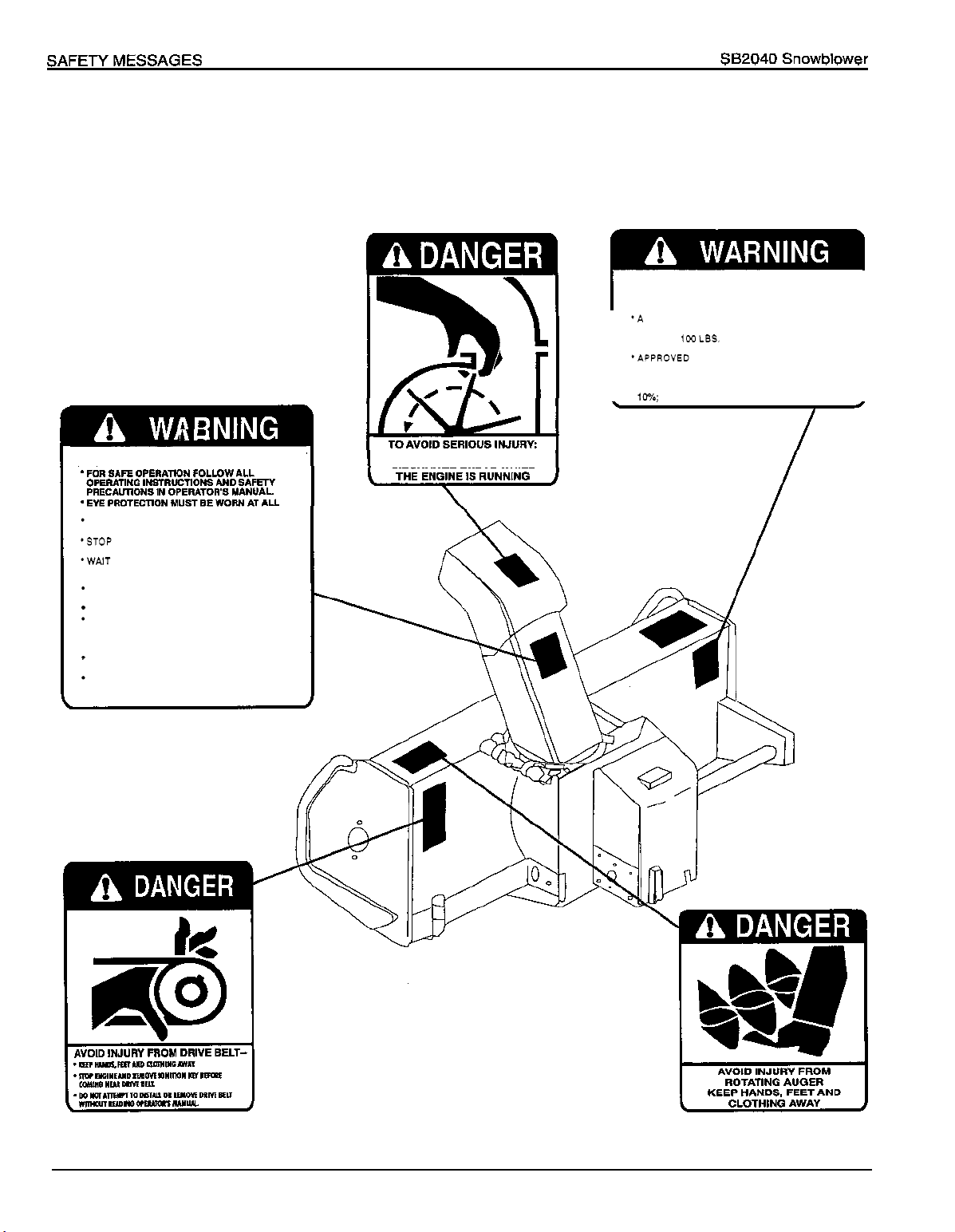
Labels
Immediately replace any label that becomes damaged or unreadable. Contact a servicing Honda lawn
tractor dealer for replacement label.
I
TO
AVOID
USING SNOWBLOWER
*A REAR COUNTERWEIGHT
COUNTERBALANCE SNOWBLOWER WEIGHT
*MINIMUM
RECOMMENDED
*APPROVED TIRE CHAINS ARE REQUIRED
I
'WHEN DISMOUNTING SNOWBLOWER, REMOVE
REAR COUNTERWEIGHT
'DO
NOT OPERATE ON SLOPES GREATER THAN
1%
I
INJURY WHEN
IS
REQUIRED TO
100
LBS. COUNTERWEIGHT
READ OPERATOR'S MANUAL
IS
I
I
I
mlm
FAILURE TO FOLLOW SAFE OPERATING PROCEED
URES MAY RESULT IN INJURY.
TIMES.
KEEP HANDS, FEET
FROM
POWER DRIVEN PARTS.
*STOP ENGINE BEFORE LEAVING OPERATOR
POSITION.
*WAIT FOR ALL MOVEMENTS TO STOP BEFORE
STARTING TO ADJUST, LUBRICATE, CLEAN
UNCLOG THE MACHINE.
KEEP THE AREA OF OPERATION CLEAR OF
ALL PERSONS AND ANIMALS.
KEEP ALL GUARDS AND SHIELDS IN PLACE.
NEVER DIRECT DISCHARGE TOWARD BY
STANDERS, BUILDINGS, CARS ETC.
'ALWAYS USE A DUST MASK WHEN WORKING
IN DUSTY CONDITIONS.
KEEP PLASTIC MATERIALS AWAY FROM
INTENSE HEAT AND OPEN FLAME.
NEVER ALLOW PASSENGERS ON THE
ATTACHMENT.
AD
AND
CLOTHING AWAY
OR
-
KEEP
HANDS
OUT
OF
DISCHARGE CHUTE WHILE
THIS
/
4
POP
52152 (9610)
Page 6
SB2040
Snowblower Assembly and Installation
Assembly and Installation
Proper installation of the SB2040 includes installing four (4) 26-lb.
counterweights. These counterweights are not included with the
snowblower and must be purchased separately.
1. Remove the lag bolts holding the blower head and the pulley
assembly to the shipping pallet.
2.
Remove the blower head and pulley assembly from the pallet.
3.
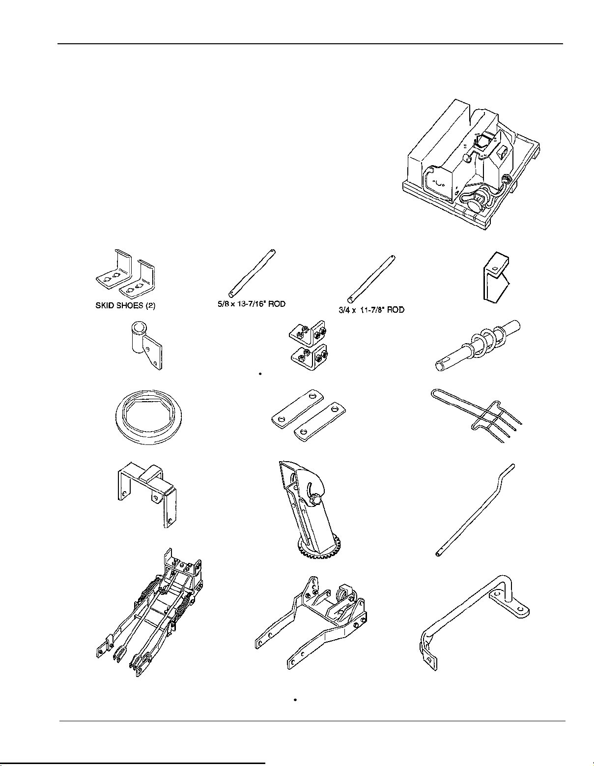
Remove the loose parts
box,
then inventory the contents.
Inventory Loose
WORM SUPPORT BRACKET L-SHAPED BRACKETS
ANTIFRICTION RING
Parts
LIFT PLATE
(2)
(2)
HOLD-DOWN
WORM GEAR
DISCHARGE
BRACKET
GUARD
POP
COUNTERWEIGHT
SUBFRAME
52152
(9610)
B
RACKET
ASSEMBLY
DISCHARGE CHUTE
PUSH FRAME
These brackets (and associated hardware) are loosely installed on
the subframe of units with serial numbers from
HANDLE
HANDLE SUPPORT
1000001 - 1000500.
5
Page 7
Assembly
and
Installation
SB2040
Snowblower
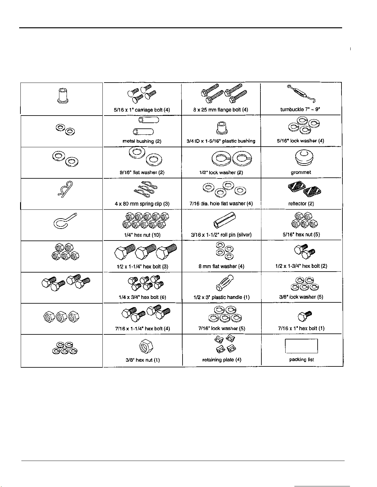
Inventory
Hardware
Bags
Refer to the serial number (located on the right side of the blower head) and check all hardware.
The following parts are included with all units:
I
3/4" ID x 1-1 1/16" plastic bushing
flat washer (2)
1/2"
6" flat washer (2)
5/1
I
2.5 x 40
mm
handle
spring clip (1)
hook
(1)
6" hex nut (5)
7/1
1/4"
x
1/2" hex bolt (4)
"
hex nut
1/2
I
1/2
"
lock
(3)
washer (5)
6
POP
52152 (9610)
Page 8

SB2040
Snowblower
Assembly
and Installation
The following parts are included only with serial number
in the shaded boxes are not required for assembly and installation of the snowblower.
The following parts are only included with serial number
I
5/16 x 3/4
"
hex bolt
(4)
I
3/8" flat washer (4)
1000001
1000501
I
5/16
lock
-
1000500
and up:
washer
(E)
only.
I
The parts indicated
PCP
e@@
3/8 x 1 hex bolt (5)
POP
52152
(9610)
7
Page 9

Assembly and Installation
SB2040
Snowblower
Hardware Measuring
How to measure hardware and components:
INCHES
0
I
I I
0
10
MILLIMETERS
5/8 In 9/1 6 In 1/2 In 7/16 In 3/8 In 5/16 In 1/4 In
20
1
I I
30
00
5mm 6mm
WASHERS ARE
BY
INSIDE DIAMETER
8mm
10mm 12mm
Chart
lT
40
2
I
50
lr
I
I
60
70 80
14
rnm
3
I
I
90
100 110 120 130 140 150
16
rnm
NUTS ARE SPECIFIED
BY
INSIDE DIAMETER
(AT THREAD DEPTH)
4
I
I
5
I I
I
INSIDE
DIAMETER
6
I
Torque Values
Fastener
I
nut
mm
I
I
/
bolt, 1/4"
bolt, 5/1 6"
bolt, 3/8"
bolt,
flange
Hex nut
Hex nut
Hex
Hex nut I bolt, 7/1 6"
8
x
25
I
Size
1/2"
bolts
Nom
-
47
41
-
70 Hex nut
61
9-1
9
ft-lb.
5-6 6.8-8.1
-
12 14-16
10
20-23 27-31
30-35
45-52
7.2- 14
8
POP
52152
(9610)
Page 10

SB2040
Snowblower
Assembly
and Installation
Assemble the Snowblower
FOLLOW THESE INSTRUCTIONS CAREFULLY. Correct installation of this snowblower is essential for
safe, reliable operation.
Push Frame Installation
Position the blower head on its front end as
1.
shown.
Slide the push frame assembly into the blower
2.
head.
-
Install and finger
3.
bolts, 7/16
7/16"
hex nuts to the front holes.
"
tighten two 7/16 x 1-1/4" hex
flat washers, 7/1 6" lock washers and
4.
Install
7/16
7/16"
Hold the edges of the push frame parallel to the
5.
two
additional 7/16 x 1 -1/4" hex bolts,
"
flat washers, 7/16" locking washers and
hex nuts to the rear holes.
edges of the blower head, then tighten all
hardware.
Install Belt to Idler Pulley
1. Locate the 3/8 x 1-3/4" hex bolt securing the idler
pulley to the push frame. Loosen this bolt
enough to allow the belt guard to be moved.
2.
Locate the belt where it exits the bottom of the
blower head. Install the belt onto the idler pulley
with the wide, flat side of the belt against the
pulley as shown.
BELT
GUW!W
3. Position the belt guard straight up. Adjust the
gap between the guard and the pulley to
-
1/8
POP
52152 (9610)
3/16" (3
-
5 mm)
and tighten the hex bolt.
PUSH
FRAME
9
Page 11
Assembly and Installation
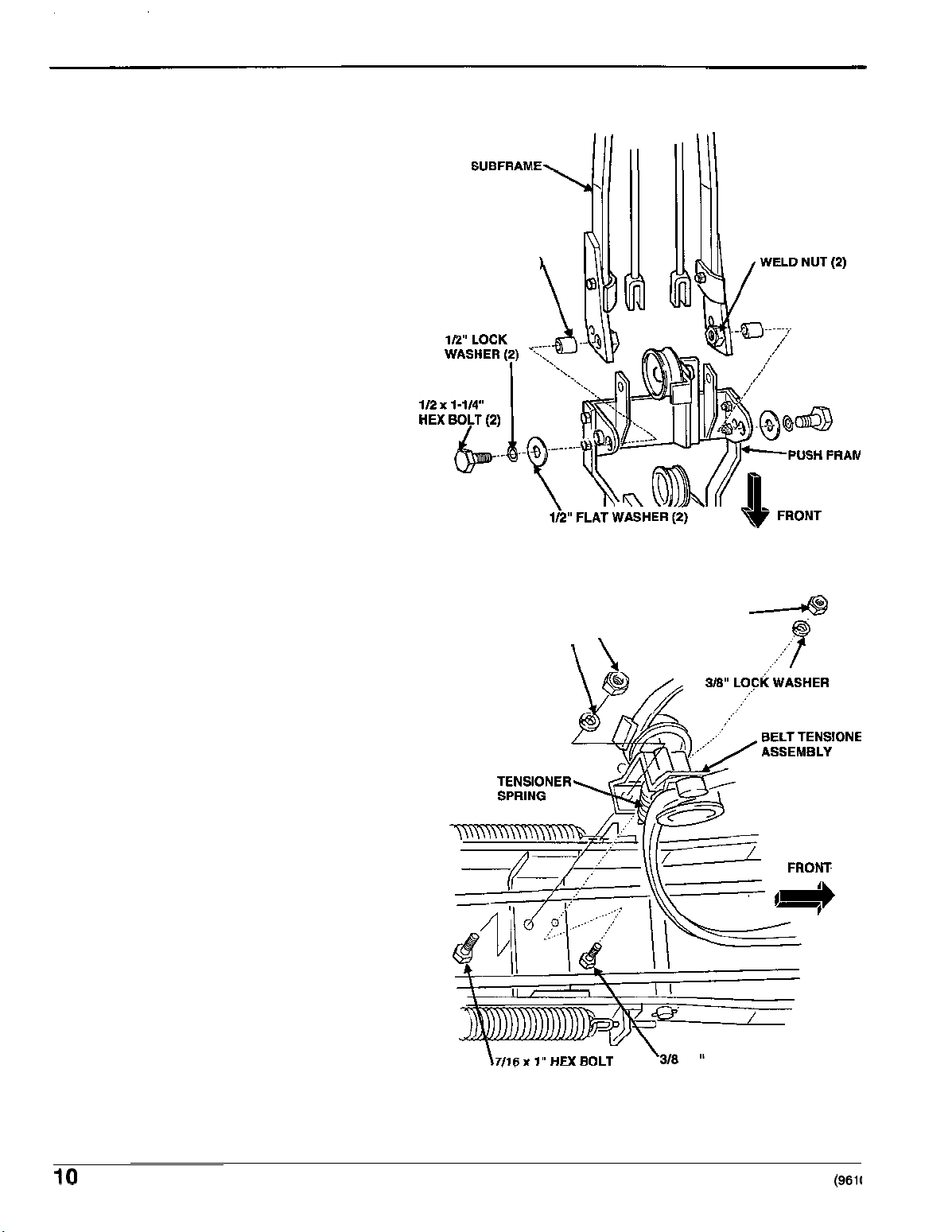
Install Push Frame to Subframe
1. Position the push frame to the subframe as
shown.
1-5/16
"
BUSHING
(2
SB2040
Snowblower
2. Install
two
washers, and
weld nuts
two
1-5/16" bushings, then install
1/2 x 1-1/4" hex bob, 1/2" lock
two
1/2" flat washers to the
on
the push frame. Tighten the
two nuts securely.
For clarity, the drive belt is not shown in
this illustration.
Install PTO Clutch Assembly
1.
Position the assembly as shown. Make
sure the belt is fully enclosed inside the
push frame, and the tensioner spring
faces away from the blower head.
2.
Install the assembly to the push frame
using 3/8 x 1" hex bolt, 3/8" lock washer
and 3/8" hex nut in the front (closest to the
blower head) hole, then install a 7/16
hex bolt, 7/16" lock washer and 7/16" hex
nut to the rear hole in the subframe.
" x 1
7/16
7/16
LOCK
"
HEX NUT 3/8" HEX NUT
WASHER
A
10
318
x
1
"
HEX
BOLT
POP 52152
(961(
Page 12
SB2040
Snowblower
Assembly and Installation
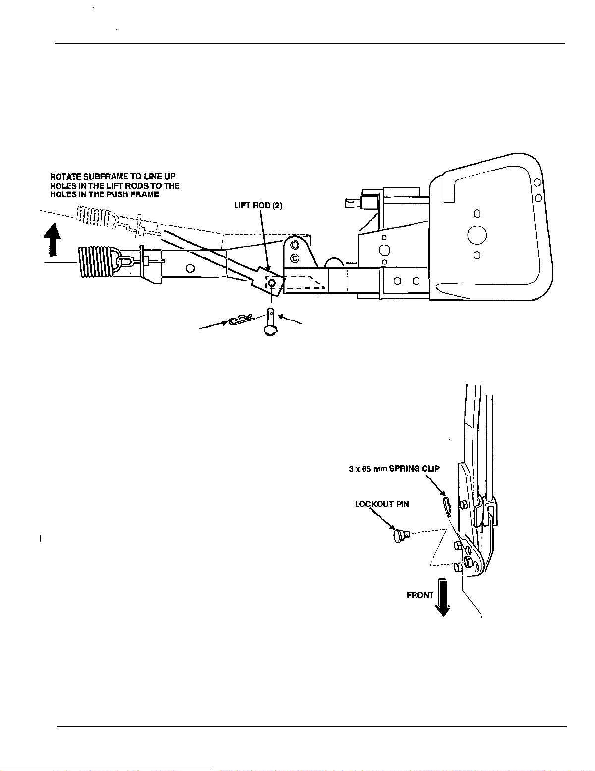
Connect Lift
Rods
1. Allow the subframe to pivot (while the blower head remains stationary), so you can connect the two lift
two
5/8
rods to the subframe using the
2.
Verify that the
4 x 80
mm
two
counterbalance springs remain connected at both ends.
SPRING
CLIP
/
x 1-5/8" clevis pins and 4 x 80 mm spring clips.
5/8
x
1-5/8"
CLEVIS
PIN
Engage Lockout Pin
The counterbalance springs transfer the weight
frame (and blower head) against the subframe. This
arrangement allows the height adjustment lever to easily
raise and lower the entire blower head. The push frame
must be locked into position (using the lockout pin) before
the springs can be properly adjusted.
Once the counterbalance springs are adjusted, they are
under tension. The lockout pin must be kept in the locked
position until the entire snowblower is fully installed.
1.
Place a suitable block of wood or other support under
I
the push frame,
2.
Adjust the position of the subframe as needed to slide
so
the subframe can pivot downward.
the lockout pin through the push frame and into the
corresponding hole in the subframe. Secure the lockout
pin with a 3 x 65 mm spring clip.
3.
Verify the lockout pin is correctly installed by attempting
to pivot the subframe
on
the push frame.
of
the push
POP
52152 (9610)
11
Page 13
Assembly and Installation SB2040 Snowblower
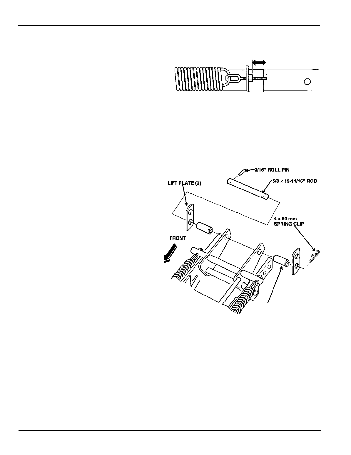
Adjust Counterbalance Springs
75
mm
1.
Tighten the adjustment nut on each
counterbalance spring bolt
so
the exposed thread
length is 75 mm (3.0 inches).
2.
Lift the subframe and remove the block of wood or
support.
After the counterbalance springs have been
adjusted, they are under tension. Do not remove
the lockout pin until the entire snowblower is fully
installed on the lawn tractor.
The effort required to raise and lower the blower
head can be adjusted by varying the length of
exposed thread on the spring bolts. See the
Maintenance
Install
Lift
section for details.
Plates
1. Install a 3/16" roll pin into one hole on the
5/8 x 13-1 1/16" rod. Install one lift plate and
metal bushing on the rod and slide them
against the roll pin.
(3.0
inches)
2.
Insert the other end of the rod through the
holes
in
the subframe as shown. Install the
other metal bushing and lift plate, then a
4 x 80 mm spring clip.
The remaining holes on each lift plate will
attach to the two lifting arms on the lawn
tractor when the snowblower
is
installed.
METAL
BUSHING
(2)
12
POP
52152 (9610)
Page 14

SB2040 Snowblower Assembly and Installation
Discharge Chute Assembly
1. Install the discharge guard on the chute as shown using two
3/8" lock washers and 3/8" hex nuts.
2. Place the antifriction ring onto the blower head; the ring is keyed to the blower head so only one
position fits.
3/8-3/4" hex bolts, 3/8" flat washers,
3. Apply a generous amount
4. Install the long (1-11/16")
surface of the bushing.
DISCHARGE GUARD
1/4" x 3/4" HEX BOLT (2)
1-5/16'' PLASTIC BUSHING
WORM GEAR
of general purpose grease to the top lip of the antifriction ring.
plastic bushing into the worm gear bracket. Apply grease to the inside
3/8" HEX NUT
3/8" LOCK WASHER
3/8" FLAT WASHER
1/4" X 3/4" HEX BOLT (6)
-
RETAINING PLATE
(2)
(2)
(2)
(3)
$//
1/4" HEX NUT (6)
5. Grease the inside of the shorter (1-5/16") plastic bushing then slide it onto the short shaft of the worm
gear. Grease the long shaft on the worm gear, and install
6.
Position the chute on the blower head. Get a helper to hold it in place
7.
Install the
two
front retaining plates using four 1/4 x 3/4" hex bolts, lock washers and hex nuts.
it
into the bushing on the worm gear bracket.
if
needed.
8. Install the short shaft of the worm gear (with bushing) into the
3/4"
bracket on the blower head.
9. Use the 1/4 x
3/4" hex bolts to install the left rear retaining plate
HEX BOLT
along with the crank handle bracket.
10. Apply a generous amount of general purpose grease to the worm
gear and chute gear teeth.
11. Use the longer, 1/4 x 3/4" hex bolts to secure the right rear
retaining plate, hold
POP
521
52
(961
0)
-
down bracket, and the plastic chain cover.
1/4"
L
1/4" HEX NUT
13
Page 15
Assembly and Installation SB2040 Snowblower
Skid Shoe Installation
1. Insert one 5/16 x
hole of each skid shoe. Loosely attach a 5/16
1"
carriage bolt into the lower
"
lock washer and 5/16" hex nut.
2.
Slip the carriage bolt head into the keyhole
opening in the lower, rear outside corner of the
blower head.
3.
Install the other 5/16 x
1
"
carriage bolt, lock
washer and hex nut as shown. Tighten both hex
bolts securely.
4. Repeat for the other skid shoe on the other side
of the blower head.
5.
The holes in the skid shoes are slotted
skid shoes may be adjusted. See the
so
the
Operation
chapter for details on adjusting the skid shoes.
/
5/16" CARRIAGE BOLT (2)
/16"
LOCK WASHER
5/16
"
HEX
NUT
(2)
(2)
I
Installing the
Snowblower
Remove the Mower Deck
Follow the procedure in the
and front links from the lawn tractor.
H2013
Owner's Manual or
H20133
Shop
Manual,
and remove the mower deck
Remove Optional Trailer Hitch and / or Grass Bag Supports:
Remove the trailer hitch and/or the grass bag supports
The counterweight bracket cannot be installed with the trailer hitch or grass bag supports.
if
either are installed on the lawn tractor
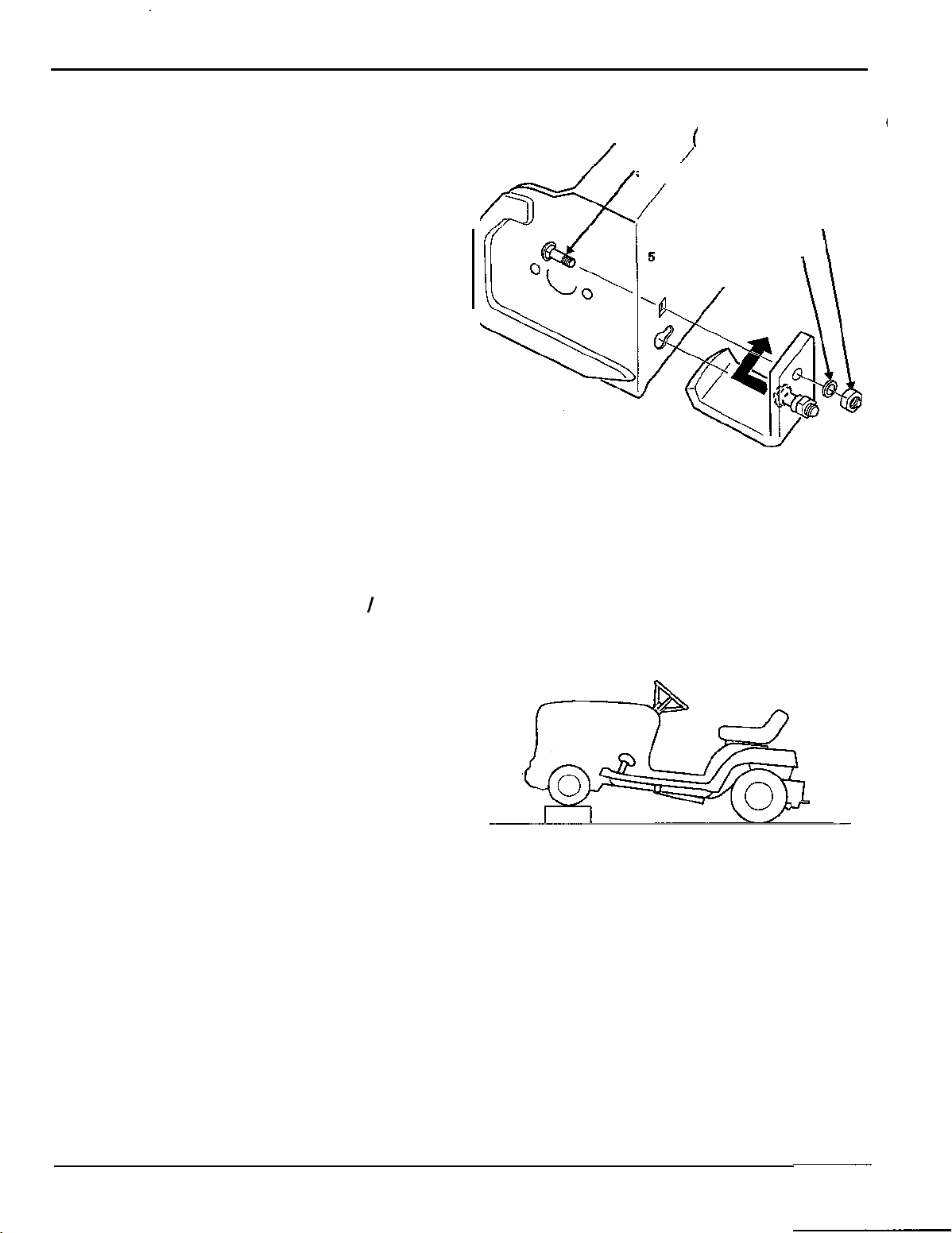
Raise and Support the Lawn Tractor
1. Raise the front end of the lawn tractor, and then
support it by placing a 4 x 4" board under each
front tire.
2. Engage the parking brake, remove the ignition
key, and disconnect the spark plug cap.
14
POP
521 52
(961
0)
Page 16

SB2040
Install
Snowblower
Brackets
1. If already installed, remove the hardware and
the I-shaped brackets from the subframe of the
assembled snowblower.
2.
Install the I-shaped brackets to the lawn tractor
frame using two 5/16 x
washers as shown. Make sure the I
3/4" bolts and 5/16" lock
-
shaped
brackets are installed on the outside of the
lawn tractor frame.
3. Remove the u
-
shaped bracket and hardware
from the subframe.
5/16"
HEX BOLT
L
-
SHAPED BRACKET ON
(4
'
N
I/
5/16''
LOCK
I
-
SHAPED BRACKET ON
L
RIGHT SIDE OF TRACTOR FRAME
4. Loosely install (don't tighten) the u-shaped
two
bracket to the
3/8 x 1"
5.
Raise the height adjustment lever as far as
hex bolts and 3/8" lock washers.
I-shaped brackets using four
possible.
Install the Snowblower
1.
Position the snowblower assembly directly in
front of the lawn tractor. Raise and support the
blower head, then slide the snowblower
assembly user the lawn tractor
subframe holes are about 1/4" further back
from their corresponding holes in the u-shaped
bracket.
2.
Lower the height adjustment lever all the way
down.
lift
3. Connect the
plates to the rear lift arms on
the lawn tractor using the same spring clips
and flat washers used for the mower deck.
so
the
3/8
x
1" HEX BOLT
SPRING CLIP
FLAT WASHER
from
MOWER
LIFTING ARM
(on lawn tractor frame)
(2)
(2)
DECK
(2)
(4)
POP
52152
(9610)
15
Page 17

Slowly lift the subframe with the height
4.
adjustment lever,
so
the hole on the left side of
the subframe aligns with the rear hole on the
-
shaped bracket.
u
Loosely install a single 3/8 x 1-1/4" bolt through
the rear holes only on each side of the
-
shaped bracket and secure with a 3/8" lock
u
washer and hex nut.
Make sure the subframe remains on the
-
outside of the u
shaped bracket.
SB2040
Snowblower
For clarity, the l
-
brackets and lawn tractor
frame are not shown in this illustration.
Raise the blower head enough
5.
so
the forward
holes in the subframe align with the holes on
the tractor frame. Raise or lower the blower
head to align the holes vertically, and push or
pull the blower head to align the holes
horizontally. Install
two
1/2 x 1-3/4" hex bolts,
1/2" lock washers and 1/2" hex nuts
two
Install
6.
and hex nuts into the
u
-
shaped bracket. For clarity, the l-brackets
3/8 x 1-1/4" hex bolts, lock washers
front
holes of the
and lawn tractor frame are not shown in this
illustration.
7.
Securely tighten the 3/8 x 1
1/2
X
1-3/4" bolts.
-1/4"
bolts and
1/2"
HEX NUT (2)
1/2"
LOCK WASHER (2)
1/2
x
1-3/4"
HEX
BOLT
FRONT
(2)
3/8 HEX NUT (2)
Raise the height adjustment lever as far as
8.
not
possible. This will
be the highest position on
the lawn tractor; do not force it any higher.
Remove the supports from under the blower
9.
head. Lower the height adjustment lever all the
way down.
Disengage the lockout pin by removing its
10.
spring clip, then pulling the lockout pin out
slightly. You may have to have a helper lift the
blower head slightly to relieve any tension on
the lockout pin.
11. Replace the spring clip on the lockout pin to
secure it in the disengaged position.
16
POP
52152
(9610)
Page 18

SB2040 Snowblower
Connect Drive Belt &
1.
Make sure the mower deck belt guard around the
crankshaft pulley has been moved out of the
way. This is typically done when the mower deck
is removed.
2. Make sure the PTO clutch lever is OFF.
3.
Install the snowblower drive belt to the
crankshaft pulley, then install the belt guard.
Tighten the silver-colored flange bolt securely.
4. Install the connecting rod from the pivot on the
u
-
shaped bracket to the slot on the PTO rod
using the two flat washers and 2 x 26 mm
spring clip. Make sure the connecting rod is
positioned on the right
PTO
Rod
-
hand side of the pivot.
FLAT WASHER (2)
and
2x26mm
SPRING CLIP
Connect Turnbuckle
1.
Unthread the eye bolt side of the turnbuckle
and install a
threads, then install the eye bolt back on the
turnbuckle.
5/16
"
jam nut onto the eye bolt
PIVOT PLATE ON
U
-
SHAPED BRACKET
SILVER
FLANGE BOLT
\
2.
Connect the hook bolt end (tip of hook bolt
must face out to the left side of the lawn
tractor) of the turnbuckle to the pivot plate on
the u-shaped bracket, and the eye bolt end of
the turnbuckle to the tension spring on the belt
tensioner pulley assembly.
L
I
I
HOOK BOLT
LEFT SIDE VIEW
POP
521
52
(961
0)
17
Page 19

Check Belt Routing Path
1.
Move the
PTO
clutch lever to
ON.
Verify the belt
ENGINE CRANKSHAFT PULLEY
TWIST IN BELT ON
RIGHT SIDE PULLE
has
been routed
as
shown.
SB2040
Snowblower
RIGHT SIDE
Check Belt Guards and Gap
Inspect the four belt guards on the
clutch assembly. Verify each guard
positiioned
as
shown.
Check the spacing between the the
pulleys and the four belt guards. Verify
there is
a
gap
of
1/8
-
3/16
"
(3
-
5
PTO
is
two
mm).
FIXED (LEFT SIDE) PULLEY
20 - 23
(27
-
-d
\\--
ft-lb.
31
Nrn)
MOVEABLE (RIGHT SIDE) PULLEY
REAR VIEW
18
POP
52152 (9610)
Page 20

Adjust Belt Tension PIVOT PLATE ON
1. Locate the thin metal plate inside the
tensioner spring. This plate is the belt tension
indicator.
2.
Loosen the jam nut on eye bolt side of the
turnbuckle, and then turn the turnbuckle until
the square tip of the belt tensioner indicator is
flush with the end of the tensioner spring.
Tighten the nut securely.
LEFT SIDE VIEW
ADJUST TURNBUCKLE
SO
INDICATOR
SPRING COIL
U-SHAPED BRACKET
IS
HOOK
TENSION INDICATOR
plate
(red
inside
BOLT
spring
coils)
Install Crank Handle and Crank
Install the plastic grip onto the end of the
1.
Support
crank handle rod.
Locate and remove the
2.
two
8
x
18
flange bolts on the left front side of the lawn
tractor frame, just to the rear of the left front
tire.
Install the crank support to the lawn tractor
3.
frame using
two
8
x
25
mm hex bolts and
mm flat washers.
Install the grommet into the end of the crank
4.
support, then insert the crank handle
through the bushing. (The top most hole is
used for mounting the optional light kit.)
Slip the J
5.
-
hook into the tip of the worm
gear, then install the other end into the
2.5
crank handle. Secure it with a
x
spring clip.
mm
40
mm
8
v
CRANK SUPPORT
/
'
J
-
-
H
OO
K
x
25
rnrn
HEX
BOLT
(2)
POP
52152
(9610)
19
Page 21

SB2040
Snowblower
Counterweight Installation
8
mm
FLAT WASHER
(2)
Install the rear counterweight bracket to the rear of
the lawn tractor frame as shown. Use two 8 x 25
1/2 x 1-1/4" HEX BOLT\
mm hex bolts and 8 mm flat washers for the sides
and a 1/2 x 1-1/4" hex bolt, 1/2" diameter lock
washer and 1/2" hex nut for the center. Hang the
four,
26
Ib. counter weights (purchased separately)
onto the bracket.
Install a 4 x 80 mm spring clip into one hole of the
3/4
x
11-7/8" inch rod.
Position the other tip of the rod through the
rounded slots in the counterweights, then secure
the rod in place by installing a
4 x 80 mm spring clip in the remaining hole.
SPRING
CLIP
Install Rear Reflectors
8
x
25
mm
HEX BOLT
1/2" HEX NUT
-.
-
(2)
separately)
Clean the rear fenders where the reflectors are to
be installed.
Remove the protective backing from the
two
reflectors and press them firmly onto the rear
fenders.
Verify Correct Installation
1.
Make sure the height adjustment lever is all the way up and the PTO clutch lever is OFF.
2.
Connect the spark plug cap, then start the lawn tractor and drive it
tractor to a flat, level outdoor area.
Stop the lawn tractor, set the parking brake
3.
4.
Inspect the auger, discharge chute, subframe,
ON,
and remove the ignition key.
PTO
pulley assembly, snowblower drive belt and belt
guards. Verify they are all correctly installed and all fasteners are securely tightened.
Sit in the operator's seat, then start the lawn tractor and leave the parking brake
5.
6
has warmed up for at least a minute, move the throttle to
(FAST), then engage the PTO clutch
lever.
Verify snowblower operation, then raise and lower the height adjustment lever up and down a few
6.
times. Move the PTO clutch lever to OFF, stop the lawn tractor's engine, and remove the ignition key.
Reinspect the auger, discharge chute, belt and pulley assembly and make sure they are not loose,
7.
broken or damaged.
off
the 4 x 4" blocks. Drive the lawn
ON.
After the engine
Inspect the belt path and make sure the snowblower drive belt is properly routed on all pulleys and
a.
belt guards. Verify the guard
20
-
pulley gap is set correctly on all belt guards.
POP
52152 (9610)
Page 22

SB2040
Snowblower
Safety Recommendations
Safety Recommendations
Introduction
1. The snowblower is capable of amputating hands and feet and throwing objects. Failure to observe the
following safety instructions could result in serious injury or death.
2.
Serious accidents which may cause injury or property damage can occur
guidelines are not followed. The operator is solely responsible for accidents or hazards that occur
when using the snowblower. Preventing accidents is the responsibility of every equipment operator.
Accidents can be prevented. Be careful before, during and immediately after use of any powered
equipment. The following general safety precautions must be fully understood and followed during
operation. Review these instructions frequently and never take chances. If you do not understand any
part of this manual or need assistance, contact your authorized, servicing Honda lawn tractor dealer.
Training
1. Read, understand and follow all instructions in this manual and on the snowblower before starting. To
order a replacement manual, contact an authorized, servicing Honda lawn tractor dealer, or Honda
Customer Service (page
2. Read and understand the H2013 Owner’s Manual.
45).
if
the following safety
3. Allow only responsible adults, who are familiar with the instructions, to operate the machine.
4. Know the location of all controls before operating the machine. Know how to stop the engine and
attachment quickly in case of emergency. Familiarize yourself with all safety and operation labels on
the machine and attachment.
If
these labels are damaged or not legible, clean or replace them.
Preparation
1. Wear proper clothing when operating the snowblower. Always wear sturdy footwear (preferably
steel
-
toed shoes) and hearing protection during operation.
a) Wear heavy, leather gloves whenever working near or servicing any cutting edges on the
snowblower.
b)
Do
not wear loose fitting clothing, jewelry, scarves, ties, etc., which may get caught in moving parts.
Tie up or restrain long hair.
Do
c)
d)
e) Wear long trousers.
f) Wear hearing protection.
g)
2.
telephone numbers for ambulance, fire, hospital, doctor and rescue near your telephone.
not operate the snowblower while barefoot.
Do
not wear sandals
Do
not operate the snowblower when tired,
Be prepared for an emergency. Keep a first aid kit and fire extinguisher handy. Keep emergency
ill,
or under the influence of alcohol and/or other drugs.
POP
52152
(9610)
21
Page 23

Safety Recommendations
SB2040
Snowblower
Before Operation
1.
Before each use, clear work area of objects such as rocks, toys, wire, sleds, etc., which could be
picked up and thrown.
2.
Keep the snowblower in safe operating condition. Check the following each time before use:
a) All hardware for tightness (refer to the torque table for details).
b) Inspect auger and fan blades for wear or damage. Broken pieces thrown from worn or damaged
auger or fan can cause serious injury.
c) Check for and maintain correct lawn tractor tire pressure. Check tires for cuts or bubbles. Check
wheels for damage or for missing hardware. Repair or replace as required.
d) Check the engine oil level and add oil as required. If oil level falls below the maximum fill mark, do
not run engine.
3.
Do not operate the snowblower without safety devices and shields in place and operating properly.
4. Use counterweights (purchased separately) for extra traction and proper balance.
5.
Check the lawn tractor brake function frequently. Adjust and service as required.
6.
The lawn tractor is equipped with a safety interlock system, designed to shut
operator leaves the seat while an attachment is running or the parking brake is not engaged.
interlock system is not working properly, repair it before operating the snowblower.
off
the engine when the
If
the
Correct any malfunction before using the snowblower or the lawn tractor.
Operation
1.
When starting the lawn tractor engine:
a) Disengage the PTO.
b) Set the parking brake ON
c) Move the shift lever to NEUTRAL.
Remain seated when starting the lawn tractor engine and during operation. Operate with feet flat on
2.
the lawn tractor running boards at all times.
Keep hands, feet, face, hair and clothing away from rotating parts. Stop engine before unclogging chute.
3.
When operating the snowblower:
4.
Disengage the PTO lever, shut
wait
for
all
moving parts
Run the snowblower for a few minutes after use to discharge any leftover snow; this will prevent
5.
-
freeze
Disengage the PTO lever when transporting to work area, or when the snowblower is not in use.
6.
Be aware of snowblower discharge direction and do not point it at anyone. Do not operate without
7.
discharge deflector in place.
If you strike a foreign object, disengage the PTO, shut off the engine, set the parking brake on, and
8.
remove the ignition key. Inspect for and repair any damage before operating the equipment again.
up of the auger and
to
off
engine, set the parking brake ON, remove the ignition key, and
stop before unclogging discharge chute
/
or fan.
or
auger blades.
Never carry passengers. Passengers interfere with safe operation of the snowblower. Passengers
9.
could be struck by foreign objects and/or be thrown from the machine and could be severely injured.
10. Be sure the area is clear of other people before operation. Stop the machine if anyone enters the
area.
Do not operate the machine with children, pets, or other nearby.
22
POP52152
(9610)
Page 24

SB2040
Snowblower Safety Recommendations
11. As a general rule, do not operate the machine in reverse. If it is absolutely necessary to back up:
a) Disengage the PTO clutch.
b) Check the area on the ground directly behind the machine.
c) Continue to observe area down and to the rear while backing up.
12. Approach blind corners cautiously.
13. Always observe the terrain. Watch for and avoid obstacles, stay away from holes, ditches, soft or
steep embankments and other potentially dangerous terrain.
14. Wet surfaces reduce traction and stability. Always maintain proper traction. Grip the lawn tractor
steering wheel firmly.
15.
Slow down before turning.
16. Watch out for traffic when operating near or crossing roadways.
17. Never leave a running machine unattended. Always disengage the PTO lever, set the parking brake
ON, and remove the ignition key before dismounting.
Children
1. Accidents can occur if the operator is not alert to the presence of children. Children are often attracted
to the machine and the snowblowing activity. Never assume that children will remain where you last
saw them.
2.
Never allow children to operate the machine, even under adult supervision. Local regulations may restrict
operator age. Allow only responsible adults, who are familiar with these instructions, to operate this unit.
3. Never carry children as passengers. They may fall off or be seriously injured or interfere with safe
machine operation.
4. Keep children out of the work area and under the watchful eye of another responsible adult.
5. Be alert and turn off the machine if children enter the area.
6.
Before and when backing up, look behind and down the operating area for small children.
7.
Use
extreme care when approaching blind corners, drifts, trees or other objects that may obscure
vision.
8.
Keep children away while performing maintenance or adjustments.
POP
52152
(9610)
23
Page 25

Safety Recommendations SB2040 Snowblower
Slope
1.
Operation
Slopes are a major factor in loss-of-control and tip-over accidents, which can result in severe injury or
death.
All
slopes require extra caution.
If
you cannot back up the slope or feel uneasy on it, do not
operate on a slope.
2.
Remove obstacles such as rocks, tree limbs, etc.
3. Watch for holes, ruts, or bumps. Uneven terrain could overturn the lawn tractor.
4. Always remove snow up and down the face of slopes, never across. Do not operate near drop-offs,
ditches, or embankments. The lawn tractor could suddenly overturn
a cliff or ditch, or
if
an edge caves in.
if
a wheel goes over the edge of
5. Always use counterweights for stability and extra traction.
6. Do not turn on slopes unless necessary, and then, move the PTO clutch lever to OFF, then turn
slowly and gradually downhill.
7.
Do
not start or stop suddenly when going up or down a slope. Keep all movement on slopes slow and
Do
gradual.
not make any sudden changes in speed
or
direction. Use a low gear setting
so
you will
not have to stop or shift while on the slope.
8. If the machine is unable to continue moving uphill, move the PTO clutch lever to OFF, check the area on
the ground immediately behind the machine, watch the area to the rear, and proceed backward slowly.
9.
Do
not operate unit on steep slopes where there is a risk of an overturn.
tractor on slopes greater than
10.
Use extra care when using this attachment. The extra weight can change the stability of the lawn tractor.
10%
grade. Use a slope gauge to check the slope
Do
not operate the lawn
if
you are not sure.
11.
12.
Do
not try to stabilize the unit by putting your foot on the ground.
Do
not park the machine on a hill.
____~
24
POP
521
52
(961
0)
Page 26

SB32040
Snowblower
Stopping
1. Before leaving operator’s position or leaving the machine unattended:
a) Bring the lawn tractor to a complete stop.
b) Move the PTO clutch lever to OFF.
c) Lower the snowblower all the way down.
Safety
Recommendations
d) Set the parking brake
e) Shut
f) Wait for all moving parts to come to a complete stop.
2.
Disengage the PTO clutch lever when transporting the lawn tractor or
off
the engine and remove the ignition key.
ON.
if
the snowblower is not in use.
Maintenance
Before performing any service, adjustments or maintenance on the machine:
1.
a) Park the machine on a firm, level surface.
b) Move the PTO clutch lever to OFF.
c) Lower the snowblower all the way down.
d) Move all control levers to NEUTRAL.
e) Set the parking brake ON.
f) Shut
Always wear sturdy footwear (preferably steel
2.
while performing maintenance on the machine. Do not wear
ties, etc., which could get caught in moving parts. Tie up or restrain long hair.
Auger and fan blades are extremely sharp. Use caution when servicing. Wear heavy gloves.
3.
Keep children away while performing maintenance or adjustments.
4.
off
the engine. Remove the ignition key. Allow the engine to cool.
-
toed shoes), long trousers, hearing and eye protection
loose
fitting clothing, jewelry, scarves,
Keep nuts and bolts tight. Keep equipment in good condition.
5.
Never tamper with safety devices. Check their proper operation regularly. Replace or repair as
6.
necessary.
Keep machine
7.
Frequently check components and replace when necessary. Use only factory
8.
parts. Parts manufactured by others may not
Keep all safety and operation labels
9.
replace them as needed.
10. Check the lawn tractor brake operation frequently. Adjust and service as necessary.
11. Chock lawn tractor wheels (place blocks of wood in front of and behind wheels) when performing
maintenance with the parking brake
Do
12.
POP 52152 (9610)
not inflate the tires above recommended pressures. Use a clip-on chuck to inflate tires, with an
extension long enough for you to stand to one side, and not over or in front of the tire assembly.
free
of
dirt
and
grim.
Clean
up
oil
or
fuel
be
of the same quality.
in
place.
off.
If
these labels are damaged or not legible, clean or
Securely support unit
spillage.
if
Allow
machine
it must be raised for any reason.
to
cool
before storing.
-
approved replacement
25
Page 27

Safety Recommendations
Controls
SB2040
Snowblower
Discharge Chute Rotation Crank
Rotating this crank turns the discharge chute.
Discharge Chute Deflector
This determines the angle at which snow is
discharged from the chute. The
the sides hold the chute at the desired angle.
two
locking knobs on
TURNS CHUTE RIGHT TURNS CHUTE LEFT
ROTATE
DEFLECTOR
-
Lockout Pin
The blowerhead pivots up and down on the subframe. Use the
lockout pin to lock the blowerhead
necessary when servicing, removing or installing the
snowblower.
Get a helper to raise and lower the blowerhead
pin can be engaged or released. Always secure the lockout
pin with the spring clip to prevent it from getting lost.
so
it doesn’t pivot. This
so
is
the lockout
26
POP
52152
(9610)
Page 28

SB2040
Snowblower Safety Recommendations
Preparing for
0
Read the Safety Recommendations at the beginning of this section.
0
Park the lawn tractor on a flat, level surface, Engage the parking brake, and remove the ignition key.
0
Make sure the auger blades, blower head and discharge chute are free of any debris or objects.
Snow
Removal
Verify the four counterweights (sold separately) are installed and properly secured to the rear frame.
0
If you have the optional tire chains installed, inspect them and make sure they are secure.
0
Inspect the position of the
conditions. See page
two
skid shoes, and make sure they are properly positioned for
34
for skid shoe adjustment.
Verify that the tension on the drive belt is correct. See page 19 for details on inspecting and
adjusting drive belt tension.
Position the Discharge Chute
You can adjust the angle and direction of the discharged snow. The angle must be set while the lawn
tractor is parked and the engine is
To adjust the discharge angle:
1.
Loosen the two locking knobs on either side of the discharge chute.
2.
Position the deflector at the desired angle. Tighten the locking knobs.
3.
You may need to experiment and readjust the deflector after a few trial runs.
To
adjust the discharge direction:
off.
4. Rotate the crank handle and turn the discharge chute to the desired position. The crank will not rotate
a full
360
degrees.
Setting the Height Adjustment Lever
Lift
and move the height adjustment lever to the desired position.
You can adjust the amount of effort required to raise the snowblower; see the
details.
Maintenance
section for
~ ~~
POP
52152 (9610)
27
Page 29

Safety Recommendations SB2040 Snowblower
Operating the Snowblower
Read the lawn tractor owner's manual carefully.
Be thoroughly familiar with the controls and
proper use of the lawn tractor. Know how to
stop the lawn tractor and disengage the
controls quickly.
Never allow children to operate the
snowblower. Never allow adults to operate the
snowblower without proper instruction.
Do
no allow anyone other than the operator on
the lawn tractor.
of
Keep the area
and pets.
Clothing worn by the operator should be fairly
tight and belted. Loose clothing should not be
permitted because
moving parts.
operation clear of all people
of
the danger of getting into
Tie up or restrain long hair.
1. Start the lawn tractor. After the engine has warmed for at least a minute, move the throttle to
Zr
(FAST).
2.
Verify that the blower head is properly positioned, then move the
3.
Adjust the ground speed of the lawn tractor as needed. Use the shift lever to change ground speeds,
never the throttle. For best performance, the throttle should always be set to
PTO
clutch lever to ON.
6
(FAST).
Snow Removal Methods
OKAY
Use the following patterns to avoid discharging snow in
unwanted locations and to prevent a second pass. For
clarity, assume both methods are used on a rectangular
area.
If
you can discharge snow to both sides, it is best to
start in the middle of the rectangle. Operate the
snowblower from one end to the other, discharging
snow to both sides. This method permits you to leave
the discharge chute in the same position.
If you must discharge snow to only one side, start in
one corner, then rotate the discharge chute with each
pass. This method will require a bit more effort, but the
snow will be discharge only to one side.
w
FINISH HERE
4
OKAY
ROTATE
CHUTE180'
TO DISCHARGE
TO
DISCHARGE
A
7
L
I
SNOW
SNOW
TO THIS SIDE
TO
THIS
SIDE
START HERE
L
V
ROTATE\
FINISH HERE
DISCHARGE
SNOW
TO
THIS
28
SIDE
ONLY
POP
521 52 (961
0)
Page 30

SB2040
Snowblower Safety Recommendations
You can be seriously injured by the fan or
auger blades.
The blades spin and can cut or amputate your
hand or fingers.
Never attempt to clear a clog with your hand;
always use a stick at least 36
"
in length to clear
a clogged discharge chute or auger.
When removing snow, do not use the snowblower as a dozer blade to push snow. Let the snowblower
works its way through deep drifts.
the travel speed
of
the lawn tractor is too fast, the snowblower may
If
become overloaded and clog. For best results, raise the snowblower and remove a top layer of snow.
second pass will remove the remaining snow.
Always operate the lawn tractor with the throttle set to
(FAST).
Using other throttle settings can reduce
6
performance and clog the discharge chute.
A
POP
521 52 (961
0)
..
29
Page 31

Removing the Snowblower SB2040
Snowblower
Removing
1.
Make sure the PTO clutch lever is
2.
Drive the lawn tractor to a flat, level surface, turn the engine
parking brake
3.
Raise the front tires and support them squarely on top of
4.
Remove the silver-colored bolt that holds the
the
Snowblower
OFF.
ON.
Disconnect the spark plug cap. Lower the height adjustment lever all the way down.
engine pulley belt guard to the right side of the
lawn tractor frame. Allow the belt guard to fall
down slightly, then remove the snowblower
drive belt from the engine pulley.
off,
two
remove the ignition key and set the
4 x 4"
blocks of wood.
DRIVE BELT
BELT GUARD
SILVER
PIVOT PLATE ON
-
SHAPED BRACKET
U
5.
Loosen the jam nut on the belt tension
turnbuckle, then lengthen the turnbuckle
enough to disconnect the J-bolt from the
PTO
pivot plate.
6. Remove the 2 x 40 mm spring clip and two flat
washers from the PTO connecting rod where it
is connected to the PTO pivot plate. Allow the
rod to fall clear from the pivot plate. Retain the
spring clip and washers when reinstalling the
snowblower or the mower deck.
FRONT
LOOSEN JAM NUT
FLAT WASHER
and
2x26mm
SPRING CLIP
REMOVE HOOK BOLT
(2)
30
POP
52152 (9610)
Page 32

SB2040 Snowblower Removing the Snowblower
7. Remove the 3.5 x 80 mm spring clip from the lockout pin,
then engage the lockout pin into the push frame. You may
need to slightly raise or lower the blower head to get the
holes in the push frame and subframe to line up; reinstall
3
X
65
mm
SPRING
C
LIP
the spring clip when the lockout pin is engaged.
1
8. Remove the 2.5 x 40 mm spring clip from
the J
-
hook end of the chute crank rod.
Remove the rod from the crank support.
Remove the J-hook from the worm gear,
-
then store the J
hook on the chute crank rod
with the spring clip.
9. If desired, you may optionally remove the
crank support by removing the
two
8 x 25 mm flange bolts from the support.
Install the
two
bolts back into the frame.
LOCKOUT
PIN
\
SPRING
CLIP
IO.
Raise the height adjustment lever all the way
up; this will not be in the maximum position,
do not use excessive force.
11. Raise and support the blower head. Remove
the
and
two 1/2
1/2"
x 3/4" hex bolts,
1/2"
lock washers,
hex nuts that hold the subframe to the
lawn tractor frame. Adjust the support on'the
blower head to relieve any binding on the
mounting bolts.
POP
52152
(9610)
so
1/2" HEX NUT (2)
1/2" LOCK WASHER
1/2 x 1-3/4" HEX BOLT (2-
(2)-y
f
31
Page 33

Removing the Snowblower SB2040 Snowblower
12. Lower the blower head slightly, then remove the
four bolts that hold the u
-
shaped bracket to the
subframe.
13. Remove the two spring clips and flat washers from
the lift arms on the lawn tractor, then disconnect
the
two
lift plates from the corresponding pins on
the lift arms. Allow the lift plates to pivot and drop
clear
of
the arms. Retain the clips and washers to
reinstall the snowblower or mower deck.
14. Remove the snowblower from underneath the
lawn tractor. Remove the four bolts that hold the
-
shaped bracket to the
u
The
two l
-
shaped brackets may remain on the
two l
-
shaped brackets.
lawn tractor frame; the brackets will not interfere
with the installation and operation of the mower
deck.
SPRING CLIP (2)
FLAT WASHER (2)
MOWER
LIFTING
lawn tractor
ARM
DECK
(2)
frame)
(on
3/8
32
x
1
POP
"
HEX
52152
BOLT
(9610)
(4)
Page 34

SB2040
Snowblower Removing the Snowblower
15. Remove one spring clip from the
counterweight retaining rod, then remove the
rod. Remove the four suitcase weights from
the counterweight bracket.
The bracket may remain on the lawn tractor
as desired. However, the bracket must be
removed before the optional hitch or grass
bag kit supports can be installed.
Follow the procedure in either the
Owner’s Manual
or
H2013
Shop
install the mower deck.
H2013
Manual
to
POP
52152
(9610)
33
Page 35

Maintenance & Adjustments SB2040 Snowblower
Maintenance & Adjustments
Maintenance Schedule
I
Emte chains
Apply grease to antifriction ring
Apply grease to bushings
Apply grease to worm gear
Inspect and adjust
PTO
spring tension
When
Every
two
As needed
As needed
As needed
Each use
(2)
hours
Notes
use chainsaw
use general purpose grease
use general purpose grease
use general purpose grease
adjust tension if needed
Adjustments
You can be seriously injured by the fan or
auger blades.
The blades spin and can cut or amputate your
hand or fingers.
Always stop the engine, remove the ignition
key, set the parking brake
the spark plug cap before attempting any
maintenance or adjustments.
For best possible performance, the SB2040 features
oil
ON,
and disconnect
a
number of adjustments:
Skid
Shoes
The skid shoes should be adjusted based on the
type of ground surface. For level, paved surfaces,
adjust the skid shoes to permit
5.0 - 6.5
mm
(3/16 - 1/4 inch) of clearance between the bottom
edge of the blower head and the ground. For
uneven or gravel surfaces, set the clearance to
13.0 - 16.0 mm (1/2 - 5/8 inch).
To
adjust the skid shoe position, loosen (don't
two
remove) the
hex nuts on the skid shoe, position
the shoe as needed, then tighten the hex nuts.
if
Recheck the measurement and repeat
necessary.
"
CARRIAGE
16
"
LOCK
BOLT (2)
5/16''
HEX
WASHER
NUT
(2)
(2
34
!
POP 52152
(9610)
Page 36

SB2040 Snowblower Maintenance & Adjustments
Height Adjustment Lever
Effort
You may vary the amount of effort required to raise the blower head with the height adjustment lever.
This is done by lengthening or shortening the exposed threads on the two counterbalance spring
adjustment bolts. This balances the weight of the blower head against the springs, making the blower
head easier (or harder) to lift with the height adjustment lever.
However, if the blower head does not have enough weight, it may float above the surface of the snow.
For this reason, the recommend setting is to leave 75 mm
offers a good compromise between lifting effort and blower head weight.
(3
inches) of exposed thread. This setting
75 mm (3.0 in.)
To decrease lifting effort, increase the length of the
exposed threads by tightening the hex nut on each
bolt. To increase effort, loosen the hex nut on each
bolt. When making any adjustments, always make sure
the length of exposed thread is the same for both bolts.
Blower Head Angle
You may adjust the angle of the lower edge of the blower head. This adjustment will allow the blower
head to tilt forward or backward slightly.
Engage the lockout pin (page 11). Locate and loosen (don't remove) the four 7/16" hex boltsthat attach
10).
the blower head to the push frame (see illustration at top of page
angle and tighten the four bolts securely. Disengage the lockout pin.
Hold the blower head at the desired
Lubrication
Chain
The drive belt operates
other drives the auger. Both chains must be lubricated on a regular basis for proper operation.
Always park the lawn tractor on a flat, level surface, engage the parking brake, and remove the ignition
key before attempting to lubricate any of the chains.
Auger Drive Chain:
and chain located on the right side of the blower head. Put on heavy
gloves and turn the auger to lubricate the rest of the chain.
Discharge
washer, hex nut and chain cover hold-down bracket from the right
rear of the discharge chute.
Remove the plastic chain cover from the rear of the blower head to
expose the discharge fan chain.
Apply chain saw oil to the two sprockets and chain. Installation is the
reverse of removal.
Fan
two
chains inside the blower head. One chain runs the discharge fan and the
Apply chain saw oil to the main auger sprocket
Chain:
Remove a 1/4" hex bolt, retaining plate, lock
1/4"
1/4"
L
HEX
NUT
1/4 x 3/4" HEX BOLT
Discharge Chute & Worm Gear
Apply a liberal amount of general purpose grease to the outer edge of the antifriction ring on the base of
the discharge chute. Apply grease to the worm gear and the sector on the discharge chute.
Bushings
Apply a liberal amount
handle bushing. Wipe away any excess grease from the outside of each bushing.
POP
521
52
(961
0)
of
general purpose grease
to
the insides
of
the worm gear bushings and the crank
35
Page 37

Maintenance & Adjustments SB
Other Maintenance Items
Shear bolt Replacement
2040
Snowblower
The auger and discharge fan both have special shear bolts that are designed to break
if
either the auger
or fan are put under an excessive load. In the event a shear bolt does break, replace it with the bolt
specified here:
Fan, 5 x 40 mm with 1/2" shoulder, SAE Grade 8, Auger, 5 x 45 mm with 1/2" shoulder, SAE Grade 8.
See
Blower Head
Belt
Replacement
While it is
See page
not
30
in the parts listing for the locations of the shear bolts.
necessary, removing the snowblower from the lawn tractor makes this job much easier.
for the snowblower removal procedure.
Remove the Old Belt
If
the snowblower remains on the lawn tractor, remove the silver,
1.
of
the lawn tractor frame that holds the snowblower drive belt guard. Remove the snowblower drive
10
mm flange bolt on the right side
belt from the engine pulley.
3/4"
HEX
Remove the
2.
two
bolts, lock washers and flat washers from the
HOLD-DOWN
right rear discharge chute retaining plate. Remove the retaining
plate and the chain cover hold-down bracket.
BOLT
Loosen the center bolt on the idler pulley (mounted to the blower
3.
head) enough to move the belt guard out of the way, then
remove the old belt from the pulley.
Remove three
4.
5/16 x 3/4"
hex bolts holding the idler pulley
bracket and side plate.
Remove the four
5.
5/16 x 3/4"
carriage
bolts that support the pulley
shaft bearings.
Remove the pulley shaft from the blower head to remove the old
6.
belt.
Loosen (don't remove) the center bolts from the
7.
PTO
clutch pulley and return pulley on the subframe.
Remove the old belt from both pulleys.
36
POP
521
52
(961
0)
Page 38

SB2040
Snowblower Maintenance & Adjustments
Install the New Belt
1.
Installation is the reverse of removal. Refer
to
the illustration here to make sure the new belt is
properly oriented along all pulleys.
ENGINE CRANKSHAFT PULLEY
TWIST IN BELT ON
RIGHT SIDE PULLE
RIGHT SIDE
2. Make sure the belt guards are
correctly
positioned
as
Tighten the center bolt on each
pulley to 27 - 31 N'm
- 23 ft.-lb.).
(20
There should be a 3 -5 mm
(1/8
- 3/16") gap [A] between each
guard and pulley.
Belt Tension Adjustment
i
1.
Adjust the belt tension as described
on page 19.
shown.
FIXED (LEFT SIDE) PULLEY
20
-
23
(27
-
i.--_
i..,
/
ft-lb.
31
N'm)
MOVEABLE (RIGHT SIDE) PULLEY
REARVIEW
PTO OFF
POP 521 52 (961
0)
37
Page 39

Parts
Listing
SB2040
Snowblower
Parts
Blower
Listing
Head
&
PTO
Clutch
Assembly
48
38
POP52152
(9610)
Page 40

SB2040 Snowblower Parts Listing
Commercially Available
#
Description
3 bolt, hex 318" nc x 4
318"
318
"
5/16
511
318" nc 4
511
POP
4 washer, lock
5
nut, hex
8
bolt, hex 8 x 25
9 washer, lock
10 washer, flat
13 bolt, flange 318" nc x 314" 4
14 nut, flange
27 bolt, flange
30 bolt, carriage
521 52 (961
0)
Parts
"
mm
"
6'
6
"
nc x 518" 6
5I16"nc x 518" 6
Qty.
3
5
5
1
7
7
39
Page 41

Parts
Listing
SB2040
Snowblower
Discharge Chute & Crank
Rod
1
40
‘22
POP 521 52
(961
0)
Page 42

SB2040 Snowblower Parts Listing
I
Commercially Available Parts
#
Description
18 bolt, carriage 511 6"
19 bolt, hex 114
20
washer, flat
21 washer, lock 114
22 nut, hex
23 bolt, hex 114
24 bolt, hex 8
25 washer, flat 511
114" nc 10
x
"
nc x
114"
"
"
nc x 112
25
mm
6
"
nc x 1-112" 2
314"
"
~~~
Qty.
2
2
10
6
2
2
Page 43

Parts Listing
Subframe
SB2040
Snowblower
42
POP
521 52 (961
0)
Page 44

SB2040 Snowblower Parts Listing
90758-771
-SO0
Commercially Available Parts
#
Description
44
bolt, hex 1/2" nc x 1-1/4"
"
nc x 1-1/4"
"
nc x
3
"
nc x 2-1/2"
"
nc x 2
-
1.25 x 25
nc
"
nc
nc
5/1 6"
nc
"
"
"
"
.
.
,
POP
52152 (9610)
45 bolt, hex 7/16
46 bolt, hex 7/1 6 nc x 1
47 bolt, hex 3/8
bolt, hex 3/8
48
49
bolt, hex 3/8
50 bolt, hex 3/8" nc x 1-1/4
bolt,
51
52 bolt, hex m8
53
54
55
56 nut, hex
hex 3/8" nc x 1
nut, hex1/2"
nut, hex 7/16
nut, hex3/8"
Qty.
3 57
4 58
1 59
1 60 washer, lock 3/8
1 61 washer, lock 5/1 6
2
4 63
8 64 washer, flat 3/8" 12
2 65 washer, flat 5/1 6
1 66 washer, flat 10 mm 4
5 67 pin, cotter 1/8
15 68 pin, cotter 5/32
2 69 pin, cotter 5/32
#
Description Qty.
nut, stove 5/1 6"
washer, lock 1/2
washer, lock 7/1 6
62 washer, flat 9/1 6
washer, flat 1/2"
nc 2
"
"
"
"
"
"
"
x 1-1/4" 1
"
x 1
"
"
x 3/4" 1
5
16
2
3
2
2
1
1
43
Page 45

Optional Accessories
SB2040
Snowblower
Optional
A number of optional accessories are available for use with the SB2040 Snowblower. See your
authorized servicing Honda lawn tractor dealer for availability and pricing.
Accessories
Tire Chains
Tire chains are available for the rear tires. These chains greatly improve traction and are strongly
recommended when using the snowblower.
Headlight
This is a single-lamp light kit that mounts to the crank support rod. The light connects with a lighting coil
and wire that mounts to the engine flywheel
switch and 50 watt halogen bulb.
Kit
,
The light features an integrated, weather-resistant on/off
Floor Mats
A
set of rubber footwell mats are available for improved footing and grip.
44
POP
521
52
(961
0)
Page 46

1
SB2040
Warranty
Honda Power Equipment dealership personnel are trained professionals. They should be able to answer
any question you may have.
satisfaction, please discuss it with the dealership’s management. The Service Manager or General
Manager can help. Almost all problems are solved in this way.
If you are dissatisfied with the decision made by the dealership’s management, contact Honda Power
Equipment Customer Relations Office.
You can write:
Or telephone:
When you call or write, please provide us the following information:
Snowblower Warranty Service Information
Service Information
If
you encounter a problem that your dealer does not solve to your
American Honda
Customer Relations Off ice
4475A River Green Parkway
Duluth, Georgia 301 36-2565
(770) 497-6400 weekdays, 8:30 a.m. - 5:00 p.m. EST
Motor
Co.,
Inc.
Serial number (snowblower and lawn tractor frame)
0
Name
Name and address of the dealer who services your snowblower or tractor.
0
Date of purchase
0
Your name, address, and telephone number
A
of
the dealer who sold the snowblower to you
detailed description of the problem
POP
52152 (9610)
45
Page 47

Current customer service contact information:
United States, Puerto Rico, and U.S. Virgin Islands:
Honda Power Equipment dealership personnel are trained professionals. They should
be able to answer any question you may have. If you encounter a problem that your
dealer does not solve to your satisfaction, please discuss it with the dealership's
management. The Service Manager or General Manager can help. Almost all problems
are solved in this way.
If you are dissatisfied with the decision made by the dealership's management, contact
the Honda Power Equipment Customer Relations Office. You can write:
American Honda Motor Co., Inc.
Power Equipment Division
Customer Relations Office
4900 Marconi Drive
Alpharetta, GA 30005-8847
Or telephone: (770) 497-6400 M-F, 8:30 am - 5:00 pm EST
When you write or call, please provide the following information:
• Model and serial numbers
• Name of the dealer who sold the Honda power equipment to you
• Name and address of the dealer who services your equipment
• Date of purchase
• Your name, address, and telephone number
• A detailed description of the problem
Page 48

 Loading...