

Page 1
Page 2

Page 3
Introduction
Safety and Instructional Decals
Assembly
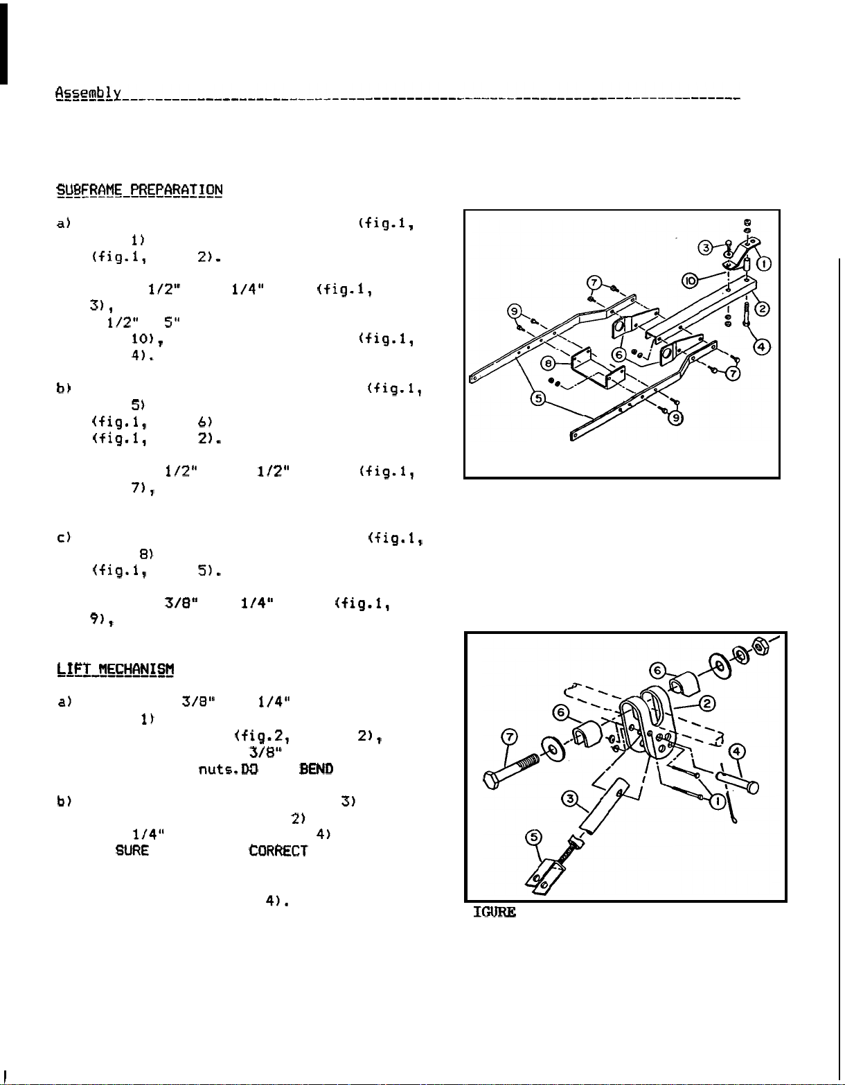
Subframe Preparation
Lift Mechanism
Tractor Preparation
Subframe Installation
Subframe Removal
Parts Guide
Torque Specification Table
Warranty Service
Thank you for purchasing an HTA attachment for your Honda Tractor.
HTA
The
Two Stage Snowblower
This manual covers the assembly, operation and maintenance of the
Hitch. For your convenience, a parts guide
available at the time of printing. American Honda Motor
to make changes at any time without notice and without incurring any obligation.
Model QH4000 Front Quick Hitch makes
.....................................................
.................................. 2
.........................................................
...........................................
.................................................
............................................
..........................................
.................................................
......................................................
........................................
.................................
it
possible
or
Dozer Blade on Honda H4013, H4514 and H4518 Lawn Tractors.
is
also included in this publication.
is
based on the latest product information
(inside back cover)
to
attach either an
Co.,
Inc. reserves the right
1
3
3
5
5
8
9
11
HTA
42
"
No
part of this publication may be reproduced without written permission.
Pay special attention to the statements preceded by the following symbols:
Indicates severe personal injury or death
are not followed.
Indicates a strong possibility that serious personal injury or
,
HTA
attachments are designed to give safe and dependable service
operated according to instructions.
If
a
problem should arise,
an authorized Honda tractor dealer.
OM
0149
death could result
Indicates a possibility that minor
are not followed.
or
if
if
instructions are
you have any questions about this attachment, consult
injury
WILL
not
followed.
can result
result
if
if
if
assembled and
instructions
instructions
Page 4
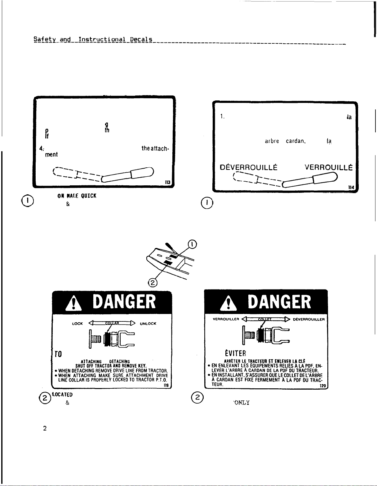
REPLACE IMMEDIATELY IF DAMAGED
.
ATTACHING INSTRUCTIONS
1.
Insert subframe into attachment completely.
2.
Lock
in
place by movin lever forward to "Lock
osition and secure wit
3.
e
ui ed with
tor%.%
If
equipped with lift assist springs, lift theattach-
and
P.T.O.
lock
UNLOCK
linch
drive line, connect
in place.
pin.
LOCK
to
trac
INSTRUCTIONS
lntroduire completement la partie male dans la
"
-
partie femelle.
2.
Placer
le
securiser avec la goupille
3.
Si
tracteur
4.
Si
accrocher.
levier dans la position "VERROUILLE" et
equipe d'un arbre
et
equipe de ressorts. lever I'instrument et les
verrouiller en place.
D'ACCOUPLEMENT
a
a
anneau.
a
PDF
du
LOCATED
(CANADA
US)
AVOID
WHEN
SERIOUS
PERSONAL
OR
INJURY
IMPLEMENT
PLACE
(CANADA
POUR
ON
MALE QUICK HITCH
ONLY
)
LES BLESSURES GRAVES:
(US
ON
MALE QUICK HITCH
CANADA
)
PLACE
ON
(CANADA
WALE QUICK HITCH
)
Page 5
----------
IMPORTANT:
level surface, parking brake
Before beginning assembly of this subframe, make sure tractor is on
is
set and that engine is turned off, with key removed.
a
item
Use
a
item
item
item
Use four 1/2"
item
tighten yet.
item
Use four
yet.
to bottom of subframe channel
a
flatwasher, lockwasher and nut, and
x
lockwashers and
x
1 1/4"
bolt, long tube spacer (fig.
lockwasher and
Do
not tighten yet.
and the
to the sides
x
lockwashers and nuts.
inside the subframe flatbars
item
x
1
bolt (fig.1, item
nut
lift
support brackets
1
nuts.
bolts (fig.1,
bolts (fig.1,
Do
of
not tighten
channel
Do
not
item
1,
FIGURE
1
item
the
lift
secure them
-
self
lift
x
2
BE
Use a
the pin (fig.2, item
OM
0149
through
lever
with
locking nuts.DC1
lever (fig.2, item 2)
pin (fig.2, item
TO
USE
5/32
"
x
x
2
the
a
smaller
uni-torque (stover)
NOT
holes
item 21, and
THE
with
as
THE
1
"
cotter pin to secure
HOLE.
in
LEVER.
to the
a 17/32
shown.
"
F
2
3
Page 6

Thread the adjustment fork (fig.2, item
into the end of the push arm (fig.2,
item
arm assembly to
Adjust the overall length of push
32
13/16".
Place an 11/16" f
retainer plate
x
4" bolt (fig.2, item
Insert the bolt into the lever
Place another bent retainer plate and
flatwasher on the bolt, and secure
loosely with a lockwasher and nut.
a
Install
into each
item
Insert the
the bearing in the right hand
support bracket.
(fig.3, item
insert the arm through the
(under the
Insert the arm through another tube
spacer, and then through the left hand
lift
support bracket bearing. The end
of the arm should protrude
the
bearing.
flange bearing (fig.3, item
lift
from the inside.
lift
latwasher and a bent
on the
as
shown.
it
support bracket (fig.3,
arm (fig.3, item
Put
on the arm, and then
a tube spacer
lift
through
lift
lever
.
2
FIGURE
3
Position the subframe channel (fig.1,
item
(fig.
bolts
Rotate the
that its handle is parallel to the
ground, and block in that position. Set
the
the
perpendicular to the ground, and then
tighten the bolt to
Install 1"
(fig.4, item
item
4
in line with subframe flatbars
1,
item
lift
lift
lever (fig.4, item
x
and securely tighten
7
and
arm (fig.4, item
4" bolt(fig.4, item 4)
lbs.
4 1/2" plastic handle
on
lift
arm (fig.4,
so
so that
is
Page 7

Loosely attach the front support brackets
(fig.5, item
For
each bracket, use one
25mm bolt (fig.5, item
and two
item.
Do
not tighten yet.
Loosely attach the attaching plates (fig.5
item
(fig.5, item
bolts (fig.5, item
for each plates.
Loosely install the reinforcement plate
(fig.5, item
plates
and nuts
the bolts heads and lockwashers from
the inside with the nut on the outside
as shown.
with lockwashers for each bracket.
to the front support brackets
bolts (fig.5, item
IN
Do
to the tractor frame.
x
with lockwasher,
x
1.25
x
Use
three
with lockwashers
Do
not tighten yet.
between the two attaching
Use
two
lockwashers
THE
FRONT
not tighten yet.
HOLES
1.25
x
5/16
Install
x
"
x
.
FIGURE
5
To
avoid injury, park the
on
tractor
parking brake.
Install male hitch (fig.6, item
a
pivot bracket
"
7/16
lockwashers and nuts. Install the bolts
from the inside
them securely.
Position the subframe assembly under
the tractor. Insert the rear of the
assembly between the wheels on the
right hand side of the tractor, and
then
OM
0149
x
pull
a level surface, turn off
1 1/4"
it
bolts (fig.6, item
as
shown, and tighten
forward.
in the
FIGURE
6
Page 8

Loosely attach front of subframe flatbars
item
plates.
Install
Do
Use
item
the
not tighten yet.
two
bolts
to
the outside attaching
x
lockwashers and nuts.
from
the inside
bolts
as
shown.
rear
item
draw
(fig. 1,
plate
item
Securely tighten the
item
to
the
with the
5/16
Refer
specification table on page
male
hitch assembly (fig.8,
hitch plate
tractor's
x
x
to
the torque
11.
rear
bolt
item
between the attaching plates (fig.7,
item
attach the hitch
the
Secure the pin with
pin on one end and
clip (hair pin)
Align the hard bushing holes and
to
the subframe with
x
10
pin (fig.8,
a
5/32
"
x
a
x
item
1
item
"
cotter
spring
at
the
other end.
NOTE: If there
male
hitch assembly and attaching plates,
is
too
much play between
use with thin flat washers included in
kit
as
shims.
Attach the fork end
item
with
a
to
the bottom of the pivot bracket
x
1
of
the push
pin and
arm
a
(fig.8,
x
spring clip (hair pin).
FIGURE
8
NOTE: The lift
arm
can be rotated
facilitate this installation.
bolts (fig.5,
items
that attach the front support
brackets
tighten the three
item
to
the support brackets.
to
the
tractor
frame, and then
bolts
that attach the attaching plates
Refer
to
torque specification chart on page
to
2
the
Page 9

Tighten the
Refer to the
bolts
Torque
Specification Table
on page
Secure the rear hitch plate
item
then the
to the tractor
bolt
1
by
tightening the
item
bolt
(fig.
item
1,
and
item
Table
If
item
on
page
11.
necessary, adjust the
so
that the handle section
lift
arm
is
parallel to the fender with approximately
1
"
of clearance when
the
way
back.
Tighten
on
the
the
lift
x
lever to
it
is
pulled a1
4
"
bolt (fig.-4, item
100
1
OM
0149
7
Page 10

T
M
I
I
installed on rear fender of tractor when
quick hitch
ANT
POR
is
Attach the two self adhesive reflectors
to the rear fender as illustrated in
figure 10.
Reflectors should be approximately
corners.
tractor
engine, remove the key, and set the
parking brake before removing the subframe.
on
I
Red ref lectors
installed.
6
"
To
avoid
a level surface,
injury,
must
park the
turn
off
be
the
FIGURE
10
with
x
5
"
from the tractor's rear draw plate.
(fig.?, item
flatbars to the attaching plates.
(fig. 8, item
by removing the
Carefully remove the front support
brackets (fig.5, item
frame, and then remove the male hitch
assembly from the tractor.
that secure the subframe
from the pivot bracket
the
lift
arm.
bolt (fig.1, item
x
1
x
1
from the tractor
pin.
8
Page 11

PARTS
1
Front support bracket
Front support bracket
Attaching plate
Attaching plate
Hex bolt
5
6
Hex
7
Lockwasher
Lockwasher 3/8"
8
Hex
9
Reinforcement plate
10
11
Hex
Lockwasher
12
13
Hex. nut
14
Pivot bracket
15
Pin
16
Cotter
Hair
18
Hex
Hex.
19
Male
GUIDE
bolt
bolt
bolt
pin 4mm x 80mm
bolt
hitch assembly
pin
nut
5/16
5/16
x
7/16
7/16
RH
LH
x
25mm
x
30mm
7/16
"
x
1
"
x
5/16".
"
10
5/32
" x 1
"
x
"
.
.
RH
LH
........
........
......
......
. . .
. .
. .
"
. . . . . .
.......
.
. . . . . .
. . . .
"
1
.
..
. .
.
.
.
. . .
1
1
1
1
2
4
6
6
1
2
2
1
1
1
1
4
4
1
REF
1
Hitch
2
Subframe channel
Hex
Tube
Lockwasher
6
Hex
7
Hex.
8
Subframe flatbar
9
Lift
Lift
11
Hex
12
Hex
13
Lockwasher
14
Hex
Support
Flatwasher,
plate
bolt
spacer
nut
bolt
support
support
bolt
bolt
nut
DESCRIPTION
x
. . .
. .
x
bracket
bracket
x
1
x
.
plate
9/16
"
. .
.
. .
. . . . . . . .
.
. .
.
. . . . .
1
L.H.
. . . . .
.
.
.
.
.
1
1
1
1
6
4
4
4
1
1
Page 12

PARTS
1
2
3
4
5
6
7
8
9
10
11
12
13
14
15
16
17
18
GUIDE
Hex
bolt
Hex
nut 3/8", Uni-torque
Lift lever
Adjustment
Push
Pin (17/32"
Cotter
Flange bearing
Lift
Tube
Hex
Flatwasher 11/16
Bent retainer
Lockwasher
Hex
Pin
Hair
Plastic handle
arm
arm
spacer
bolt
nut
pin
x
2
................
fork
...........
..................
x
2
pin
5/32
"
x
............
..................
...............
4
"
x
"
hole
plate
...........
..............
x
1
3
mm
x
65
mm
grip
....
.....
........
....
.......
.....
.......
. .
2
2
1
1
1
1
1
2
2
2
1
2
2
1
1
1
1
1
I
Page 13

TORQUE
SPECIFICATION
SEE
Size
No.
GENERAL
USE
THE
NOTE:
treme
pressure lubricants
Pounds
Min.
TORQUE
FOLLOWING
valuer
oil.
They
2
Feet
Mar.
Min. Max.
SPECIFICATION
TORQUES WHEN
to
fasteners
do
not
This
if
applies
I
SPECIAL
from
70
both
UNF
Feet
Min. Max.
TABLE
TORQUES
supplier.
or
moly
and
UNC
threads.
6
Newton-Meters
(Revised
ARE
when
I
Max.
2-74)
NOT
Pounds
with
or
other
Feet
Max.
Max.
I
M14
M16
I
8T
7T
4T
METRIC
I
2.0
2
2
BOLT TORQUE SPECIFICATIONS
57-66
49-56
81-93 109.8-126
96-109 130.1-147.7
67-77
116-130
88
-
-
I
130 146.3-1762
I
52-64
122-143.6
107
-
124 145-168
-
83 935-111-5
69
I
Page 14

Your satisfaction and goodwill are important to your dealer and to
us.
All
Honda
warranty details are explained in the Distributor's Limited Warranty. Normally,
any problems concerning the product
If
department.
you have a warranty problem that has not been handled to your
will
be handled by your dealer's service
satisfaction, we suggest you take the following action:
Discuss your problem with a member of dealership management.
If
can be quickly resolved at that level.
the problem has already been reviewed
with the Service Manager, contact the owner of the dealership
Manager.
If
your problem still has not been resolved to your satisfaction, contact the
Power Equipment Customer Service Department of American Honda Motor
American Honda Motor Co.,Inc.
Power Equipment Customer Service Department
4475
River Green Parkway
Duluth,
Telephone:
will
We
need the following in order to assist you:
o
Your name, address and telephone number
o
Product model and seri a1 number
o
Date of purchase
o
Dealer name and address
o
Nature of the problem
After reviewing all the facts involved, you
taken. Please bear
in
Georgia 30136
497-6400
will
be advised of what action can be
mind that your problem
will
likely be resolved at the
dealership, using the dealer's facilities, equipment and personnel,
important that your initial contact be
with
the dealer.
Of
ten complaints
or
the
General
S
O
it
is
very
Your
purchase of
a
Honda product
is
greatly appreciated by both your dealer and
American Honda Motor Company. We want to assist you in every way possible to assure
your satisfaction
For
future reference, record your unit's model number, serial number and date of
purchase
in
the spaces below. Refer to this information when ordering parts and
with
your
purchase.
when making technical or warranty inquiries.
Page 15

Page 16

H/C
3752482
(9307)
 Loading...