

Page 1
2000
-
06 STEERING
COMPONENT LOCATION INDEX
2006 Honda Insight
2006 Honda Insight
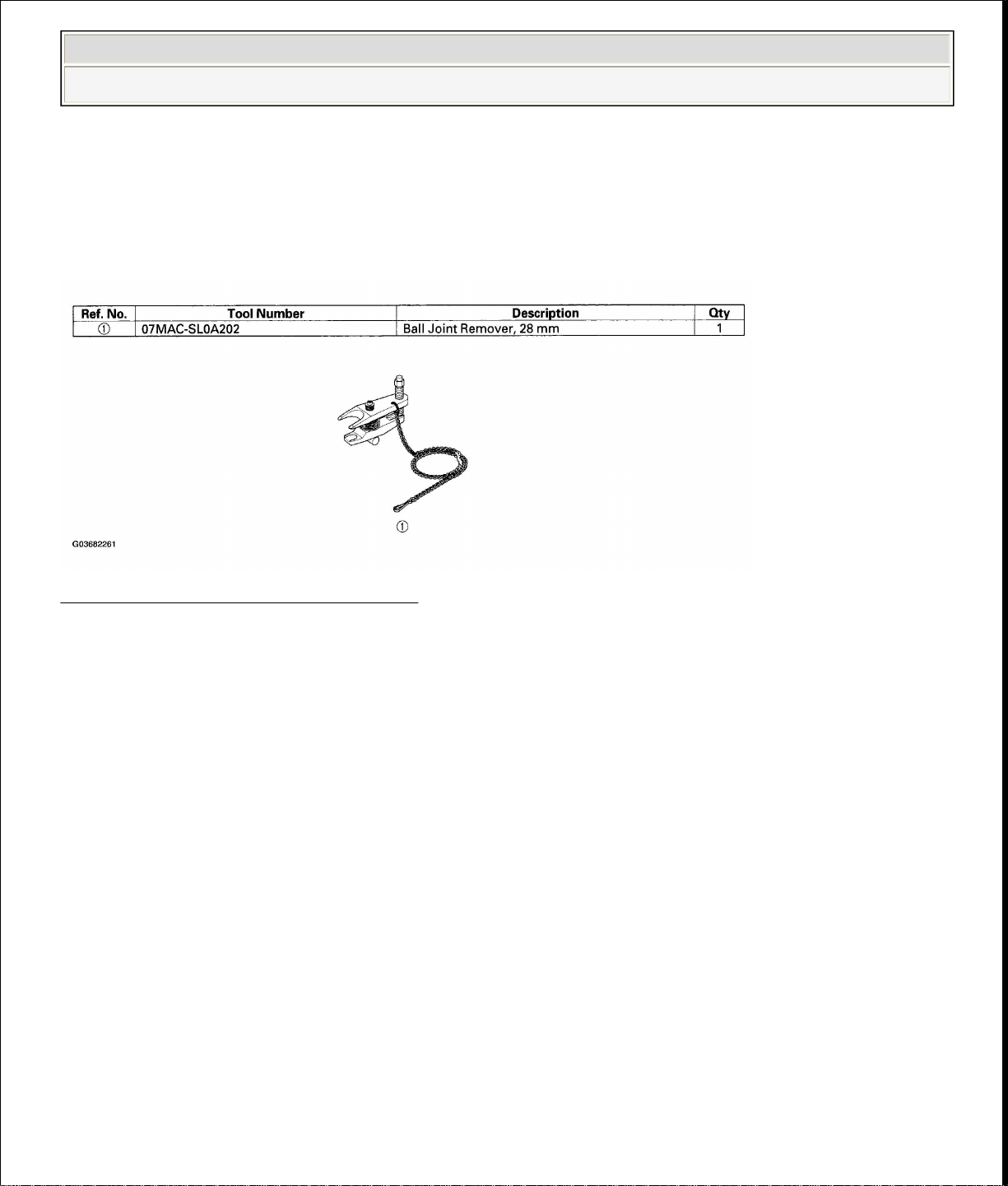
SPECIAL TOOLS
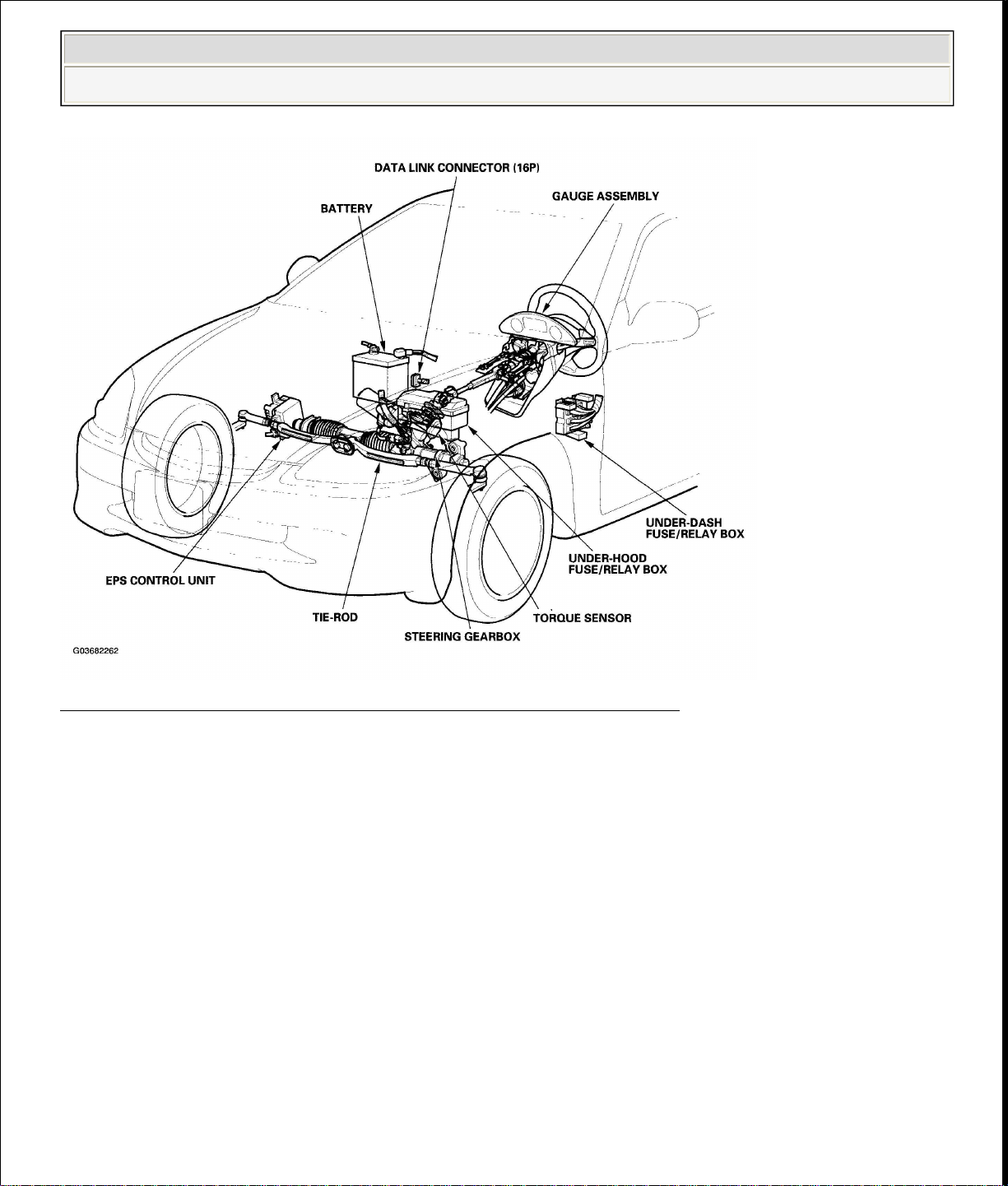
2000-06 STEERING Electrical Power Steering (EPS) - Insight
2000-06 STEERING Electrical Power Steering (EPS) - Insight
Electrical Power Steering (EPS) - Insight
Fig. 1: Identifying Special Tools
Courtesy of AMERICAN HONDA MOTOR CO., INC.
Page 2
power assist is turned off.
When DTC 11, 15, 16, 17, 18 or 67 is stored in the control unit, the EPS indicator
2006 Honda Insight
2000-06 STEERING Electrical Power Steering (EPS) - Insight
Fig. 2: Locating Electrical Power Steering Components
Courtesy of AMERICAN HONDA MOTOR CO., INC.
GENERAL TROUBLESHOOTING INFORMATION
EPS INDICATOR
Under normal conditions, the EPS indicator comes on when the ignition switch is
turned to the ON (II) position, then goes off after the engine is started. This
indicates that the bulb and its circuit are operating correctly. If there is any trouble
in the system after the engine is started, the EPS indicator will stay on, and the
When EPS indicator light comes on, the control unit memorizes the DTC. In this
case, the control unit will not activate the EPS system after the engine starts again,
but it keeps the EPS indicator on.
Page 3

is detected more than once, the most recent DTC is written over the prior DTC;
switch is turned OFF.
2006 Honda Insight
2000-06 STEERING Electrical Power Steering (EPS) - Insight
will stay on until the DTC is erased. When a problem is detected and the EPS
indicator comes on, there are cases when the indicator stays on until the ignition
switch is turned OFF, and cases when the indicator goes off automatically when the
system returns to normal. Even though the system is operating normally, the EPS
indicator will come on under the following conditions:
When the vehicle is barely moving, 1 mph (1 km/h) or stopped, and the engine
speed is 2,000 RPM or higher for above 6 minutes.
When the engine speed is 280 RPM or less, and the vehicle is traveling at a
speed of 6.2 mph (10 km/h) or more for 3 seconds.
To determine the actual cause of the problem, question the customer about the
conditions during which the problem occurred, taking the above conditions into
consideration.
DIAGNOSTIC TROUBLE CODE (DTC)
If the CPU cannot be activated, or it fails, the EPS indicator comes on, but the
DTC is not memorized.
The memory can hold a large number of DTCs. However, when the same DTC
therefore only one occurrence is memorized.
The DTCs are indicated repeatedly until the ignition switch is turned OFF.
If the DTC is not memorized, the EPS indicator will stay on.
The DTCs are memorized in the EEPROM (nonvolatile memory) therefore the
memorized DTCs cannot be erased by disconnecting the battery. Perform the
specified procedures to clear DTCs.
SELF-DIAGNOSIS
Self-diagnosis can be classified into two categories:
Initial diagnosis: Performed right after the engine starts and until the EPS
indicator goes off.
Regular diagnosis: Performed right after the initial diagnosis until the ignition
Page 4

Because this heat adversely affects the system, the control unit monitors the electric
still present and the EPS indicator is still on. Following the flowchart when the EPS
return to normal when the vehicle speed is 1 mph (1
2006 Honda Insight
2000-06 STEERING Electrical Power Steering (EPS) - Insight
The EPS control unit performs the following functions when a problem is detected
by self-diagnosis:
1. Turns on the EPS indicator.
2. Memorizes the DTC.
3. Stops power assist and manual steering operation begins.
NOTE:
When DTC 23 (a problem with the circuit for engine
speed signal) is detected, the power assist will
km/h) or above.
For DTCs 22, 23, 46, 47, 50, 64, 66 or 68 the EPS
indicator goes off automatically when the system
returns to normal. For all other codes, the EPS
indicator goes off when the system is OK after the
ignition switch is turned from OFF to ON (II).
RESTRICTION ON POWER ASSIST OPERATION
Repeated extreme steering force, such as turning the steering wheel continuously
back-and-forth with the vehicle stopped, causes an increase of power consumption
in the EPS motor. The increase of electric current causes the motor to heat up.
current of the motor.
When the control unit detects heat build-up in the motor, it reduces the electric
current to the motor gradually to protect the system, and it restricts the power assist
operation. The EPS indicator does not come on during this function.
When steering torque is not applied to the steering wheel, or when the ignition is
turned off, the control unit will restore the power assist gradually until it's fully
restored (after approximately 14 minutes maximum).
HOW TO TROUBLESHOOT DTCS
The troubleshooting flowchart procedures assume that the cause of the problem is
Page 5

2006 Honda Insight
2000-06 STEERING Electrical Power Steering (EPS) - Insight
indicator does not come on can result in incorrect diagnosis.
The connector illustrations show the female terminal connectors with a single
outline and the male terminal connectors with a double outline.
1. Question the customer about the conditions when the problem occurred, and
try to reproduce the same conditions for troubleshooting. Find out when the
EPS indicator came on, such as while turning, after turning, when the vehicle
was at a certain speed, on start up, etc.
2. When the EPS indicator does not come on during the test-drive, but
troubleshooting is done based on the DTC, check for loose connectors, poor
terminal contact, etc., before you start troubleshooting.
3. After troubleshooting, clear the DTC and test-drive the vehicle. Be sure the
EPS indicator does not come on.
HOW TO RETRIEVE DTCS
HDS (Honda Diagnostic System) Method
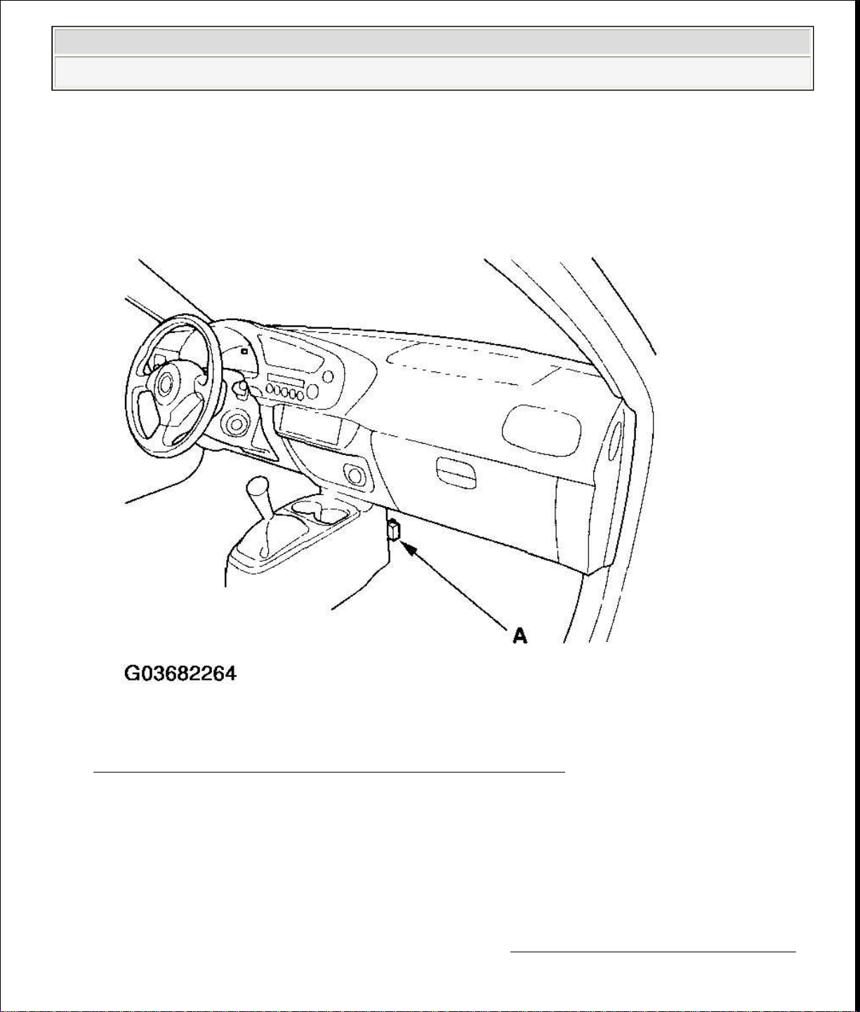
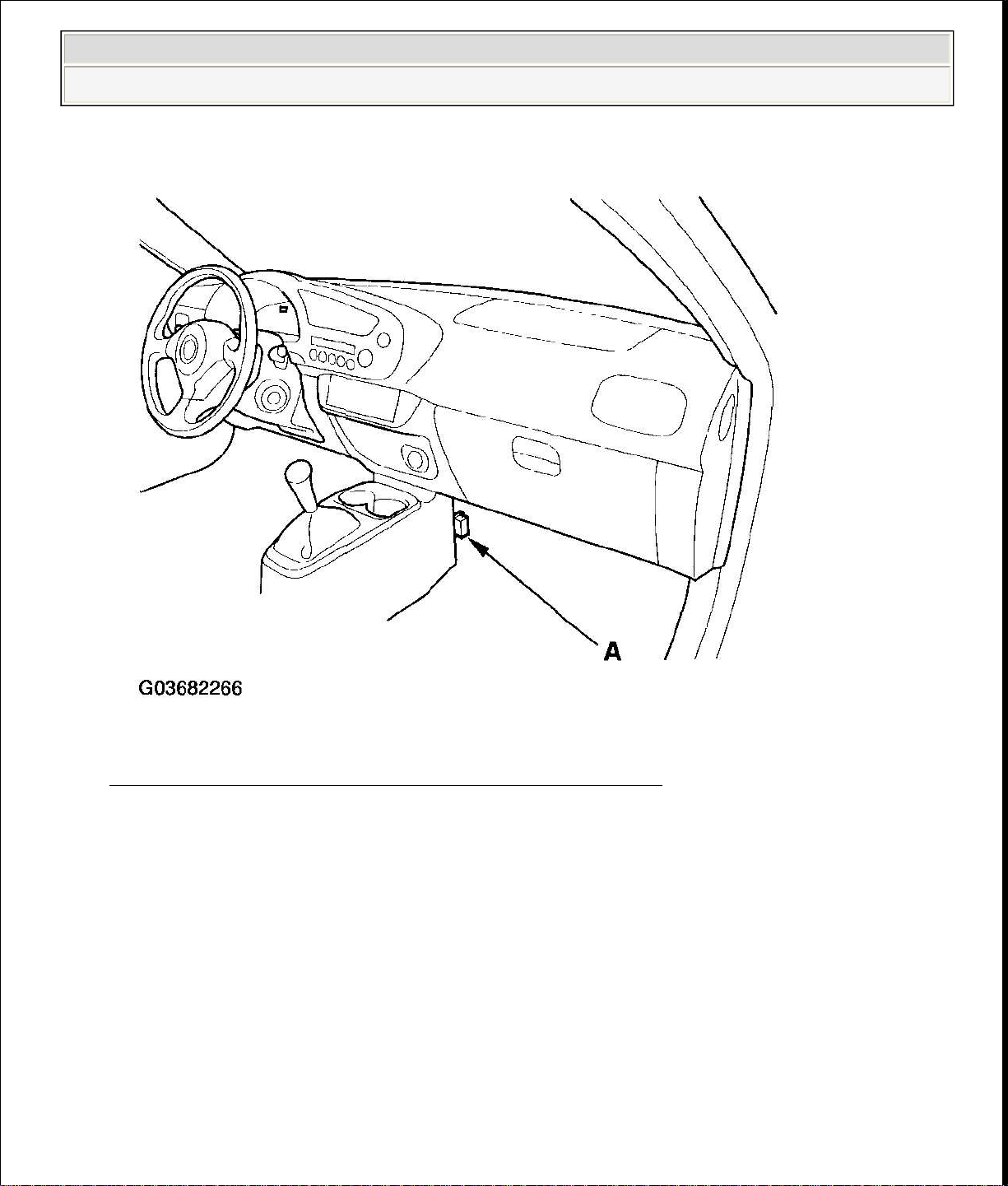
1. With the ignition switch OFF, connect the HDS to the 16P data link connector
(DLC) (A).
NOTE: The 16P data link connector (DLC) is located under the
dash on the passenger's side for '2000 model, and on
the driver's side for '2001-2006 models.
Page 6

2006 Honda Insight
2000-06 STEERING Electrical Power Steering (EPS) - Insight
Fig. 3: Locating 16P Data Link Connector (DLC)
Courtesy of AMERICAN HONDA MOTOR CO., INC.
2. Turn the ignition ON (II), and follow the prompts on the HDS to display the
DTC(s) on the screen. After determining the DTC, refer to the DTC
TROUBLESHOOTING .
NOTE: See the HDS Help menu for specific instructions
Service Check Signal Circuit Method
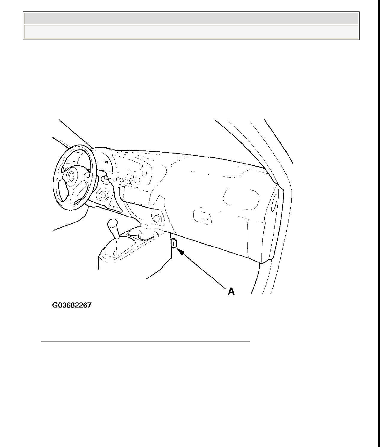
1. With the ignition switch OFF, connect the HDS to the 16P data link connector
(DLC) (A).
NOTE: The 16P data link connector (DLC) is located under the
Page 7
.
The system will not indicate the DTC unless these conditions are met:
2006 Honda Insight
2000-06 STEERING Electrical Power Steering (EPS) - Insight
dash on the passenger's side for '2000 model, and on
the driver's side for '2001-2006 models.
Fig. 4: Locating 16P Data Link Connector (DLC)
Courtesy of AMERICAN HONDA MOTOR CO., INC.
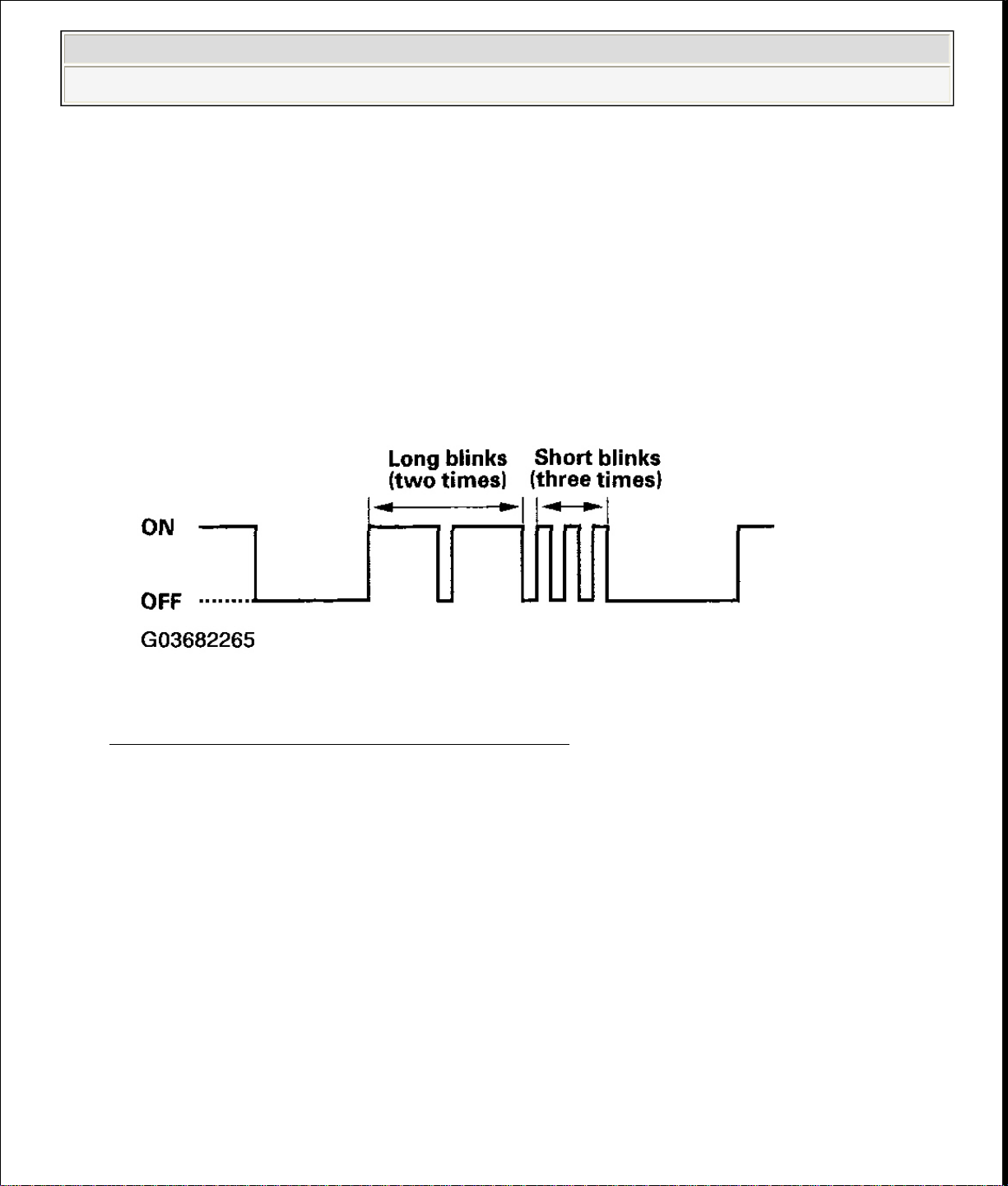
2. Short the SCS circuit to body ground using the HDS.
3. Turn the ignition switch ON (II).
4. The blinking frequency indicates the DTC. DTCs are indicated by a series of
long and short blinks. Add the long and short blinks together to determine the
DTC. After determining the DTC, refer to the DTC TROUBLESHOOTING
Page 8
2006 Honda Insight
2000-06 STEERING Electrical Power Steering (EPS) - Insight
Set the front wheels in the straight ahead driving position.
The ignition switch is turned ON (II).
The engine is stopped.
The SCS circuit is shorted to body ground before the ignition switch is
turned ON (II).
Example of DTC 23
Fig. 5: Identifying DTC Blinking Display
Courtesy of AMERICAN HONDA MOTOR CO., INC.
5. Turn the ignition switch OFF.
6. Disconnect the HDS from the DLC.
HOW TO CLEAR DTCS
HDS (Honda Diagnostic System) Method
1. With the ignition switch OFF, connect the HDS to the 16P data link connector
(DLC) (A).
NOTE: The 16P data link connector (DLC) is located under the
dash on the passenger's side for '2000 model, and on
the driver's side for '2001-2006 models.
Page 9
(DLC) (A).
2006 Honda Insight
2000-06 STEERING Electrical Power Steering (EPS) - Insight
Fig. 6: Locating 16P Data Link Connector (DLC)
Courtesy of AMERICAN HONDA MOTOR CO., INC.
2. Turn the ignition switch ON (II), and clear the DTC(s) by following the screen
prompts on the HDS.
Service Check Signal Circuit Method
NOTE: Use this procedure when the HDS software does not match
1. With the ignition switch OFF, connect the HDS to the 16P data link connector
NOTE: See the HDS Help menu for specific instructions.
the year/model vehicle you are working on.
Page 10
seconds. Within 4 seconds of turning the switch ON, while the EPS indicator is
driving position, and hold the steering wheel in that position until the EPS
2006 Honda Insight
2000-06 STEERING Electrical Power Steering (EPS) - Insight
NOTE: The 16P data link connector (DLC) is located under the
dash on the passenger's side for '2000 model, and on
the driver's side for '2001-2006 models.
Fig. 7: Locating 16P Data Link Connector (DLC)
Courtesy of AMERICAN HONDA MOTOR CO., INC.
2. With the vehicle on the ground, set the front wheels in the straight ahead
driving position.
3. Short the SCS circuit to body ground using the HDS.
4. Turn the ignition switch ON (II). The EPS indicator comes on for about 6
on, turn the steering wheel 45 degrees to the left from the straight ahead
Page 11
DTC 11: TORQUE
SENSOR VT3; DTC 15:
TORQUE SENSOR VT6;
DTC 16: TORQUE
DTC 11: TORQUE
SENSOR VT3; DTC 15:
TORQUE SENSOR VT6;
2006 Honda Insight
2000-06 STEERING Electrical Power Steering (EPS) - Insight
indicator goes off.
5. Within 4 seconds after the EPS indicator goes off, return the steering wheel to
the straight ahead driving position and release the steering wheel. The EPS
indicator comes on again 4 seconds after releasing the steering wheel.
6. Within 4 seconds after the EPS indicator comes on, turn the steering wheel 45
degrees to the left again and hold it in that position.
The EPS indicator goes off after 4 seconds.
7. Within 4 seconds after the EPS indicator goes off, return the steering wheel to
the straight ahead driving position again and release the steering wheel. The
EPS indicator blinks twice 4 seconds after releasing the steering wheel,
indicating that the DTC was erased.
NOTE: If the EPS indicator does not blink twice, an error was
made in the procedure and the DTC was not erased.
Turn the ignition switch OFF, and repeat the operation
from step 3.
8. Turn the ignition switch OFF after the EPS indicator blinks twice.
9. Disconnect the HDS from the DLC.
10. Check for the DTC again to be sure that it was erased.
DTC TROUBLESHOOTING INDEX
TROUBLESHOOTING CHART
DTC Detection Item Note
11 A problem with voltage
(see
for torque sensor VT3
SENSOR VT3 AND VT6 )
15 A problem with voltage
(see
for torque sensor VT6
Page 12
DTC 16: TORQUE
DTC 11: TORQUE
SENSOR VT3; DTC 15:
TORQUE SENSOR VT6;
DTC 16: TORQUE
DTC 17: TORQUE
SENSOR VCC1; DTC 18:
TORQUE SENSOR
DTC 17: TORQUE
SENSOR VCC1; DTC 18:
TORQUE SENSOR
average vehicle speed and
DTC 22: VEHICLE
SPEED SENSOR
SIGNAL; DTC 23:
ENGINE SPEED
DTC 22: VEHICLE
SPEED SENSOR
SIGNAL; DTC 23:
ENGINE SPEED
DTC 22: VEHICLE
SPEED SENSOR
SIGNAL; DTC 23:
ENGINE SPEED
voltage in the EPS control
DTC 37: EPS
CONTROL UNIT
INTERNAL CIRCUIT
(INPUT CIRCUIT FOR
2006 Honda Insight
2000-06 STEERING Electrical Power Steering (EPS) - Insight
16 A problem with average
of voltage for torque
sensor VT3 and VT6
17 A problem with the
voltage for torque sensor
12 V power source Vcc1
18 A problem with the
voltage for torque sensor
5 V power source Vcc2
SENSOR VT3 AND VT6 )
(see
SENSOR VT3 AND VT6 )
(see
VCC2 )
(see
22 A problem with the
engine speed
Excessive change of the
vehicle speed sensor
(VSS) signal
23 A problem with the
engine speed signal
circuit
VCC2 )
(see
SIGNAL )
(see
SIGNAL )
(see
SIGNAL )
37 A problem with the
(see
circuit for input motor
unit
Page 13
A problem with the motor
DTC 37: EPS
CONTROL UNIT
INTERNAL CIRCUIT
(INPUT CIRCUIT FOR
A problem with the motor
DTC 42, 45: MOTOR
A problem with the motor
DTC 43: MOTOR
DRIVEN CURRENT IS
A problem with the motor
DTC 42, 45: MOTOR
DTC 46,47: POWER
RELAY STUCK ON OR
DTC 46,47: POWER
RELAY STUCK ON OR
DTC 50: EPS
CONTROL UNIT
INTERNAL CIRCUIT
(CPU OR
DTC 62: EPS
CONTROL UNIT
INTERNAL CIRCUIT
SAFE RELAY
DTC 64: BATTERY
VOLTAGE IS
EXCESSIVELY LOW
SAFE RELAY
CONTACT FAILURE
2006 Honda Insight
2000-06 STEERING Electrical Power Steering (EPS) - Insight
41
voltage
42
driven current
43
driven current
45
driven current
46 A problem with the
MOTOR VOLTAGE) )
(see
MOTOR VOLTAGE) )
(see
DRIVEN CURRENT )
(see
EXCESSIVELY HIGH )
(see
DRIVEN CURRENT )
(see
power relay (relay stuck
ON or stuck OFF)
47 A problem with the
(see
power relay
50 A problem with the CPU
(see
or Microcomputer in the
EPS control unit
MICROCOMPUTER )
62 Fail-safe relay stuck ON (see
(FAIL-
64 Low battery voltage (see
STUCK OFF )
STUCK OFF )
STUCK ON) )
(FAIL-
Page 14

AND MOTOR VOLTAGE
DTC 64: BATTERY
VOLTAGE IS
EXCESSIVELY LOW
SAFE RELAY
CONTACT FAILURE
AND MOTOR VOLTAGE
A problem with the motor
DTC 66: MOTOR
DRIVEN VOLTAGE;
DTC 68: EPS CONTROL
UNIT INTERNAL
DTC 67: TORQUE
DTC 66: MOTOR
DRIVEN VOLTAGE;
DTC 68: EPS CONTROL
UNIT INTERNAL
DTC
EPS indicator does not go
DTC
2006 Honda Insight
66
2000-06 STEERING Electrical Power Steering (EPS) - Insight
Fail-safe relay contact
(see
failure
(FAIL-
(see
driven voltage
FALL OFF) )
FALL OFF) )
CIRCUIT )
67 A problem with the
torque sensor I/F circuit
68 A problem with the
(see
SENSOR I/F CIRCUIT )
(see
interlock circuit
CIRCUIT )
SYMPTOM TROUBLESHOOTING INDEX
SYMPTOM TROUBLESHOOTING CHART
Symptom Diagnostic procedure Also check for
EPS indicator does not
come on
EPS Indicator Circuit
Troubleshooting (see
67: TORQUE SENSOR
I/F CIRCUIT )
EPS Indicator Circuit
off, and no DTCs are
stored
EPS indicator is not on,
Troubleshooting (see
67: TORQUE SENSOR
I/F CIRCUIT )
Page 15

Check the motor wires
steering gearbox (short
2006 Honda Insight
2000-06 STEERING Electrical Power Steering (EPS) - Insight
no DTCs are stored, but
there is no power assist
1.
between the EPS
control unit and the
motor for a short to
ground. Repair as
needed.
2. If the motor wires are
OK, replace the
in the motor).
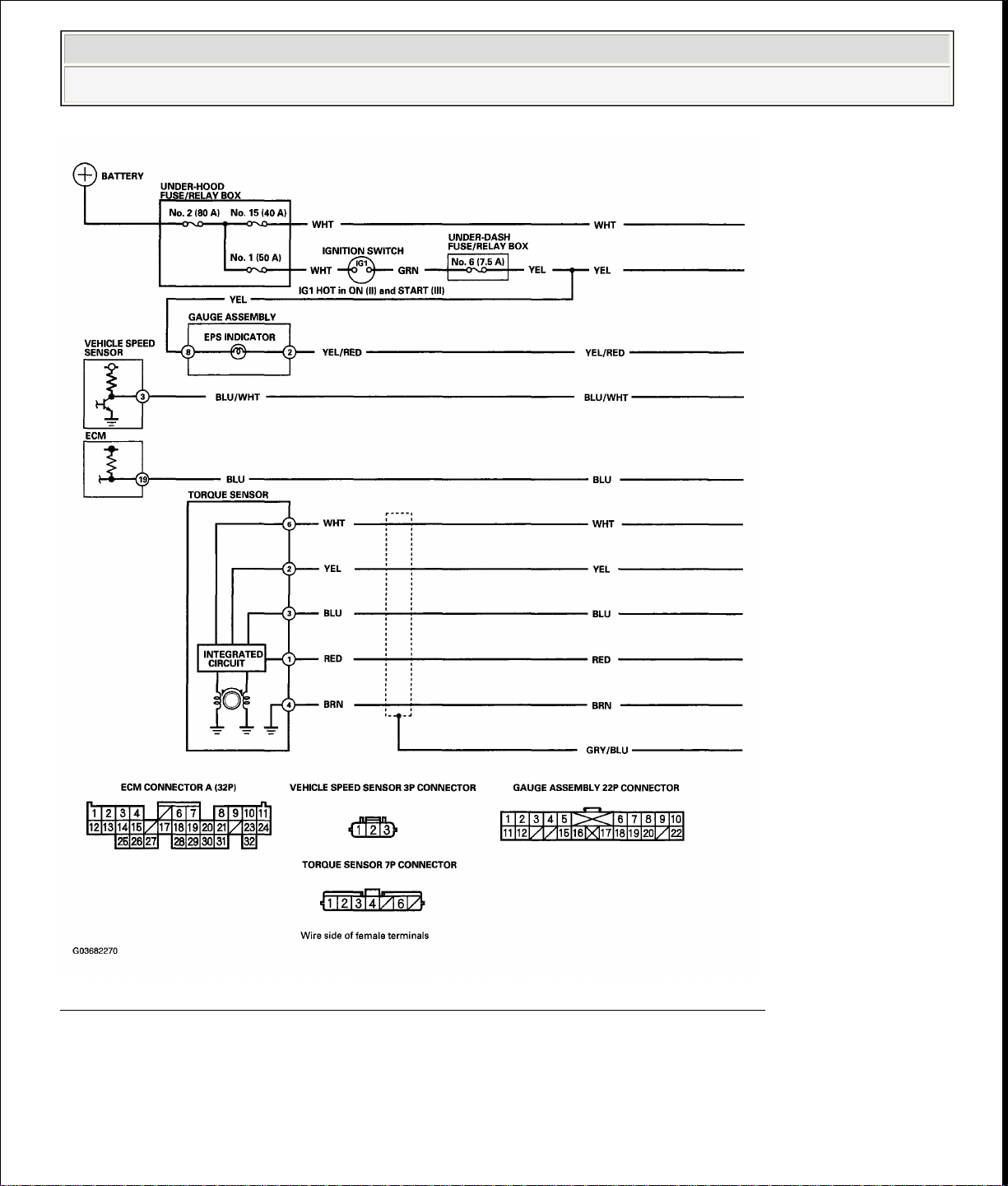
SYSTEM DESCRIPTION
EPS CONTROL UNIT INPUTS AND OUTPUTS FOR CONNECTOR A (4P)
Fig. 8: Identifying EPS Control Unit Inputs And Outputs For Connector A
(4P)
Courtesy of AMERICAN HONDA MOTOR CO., INC.
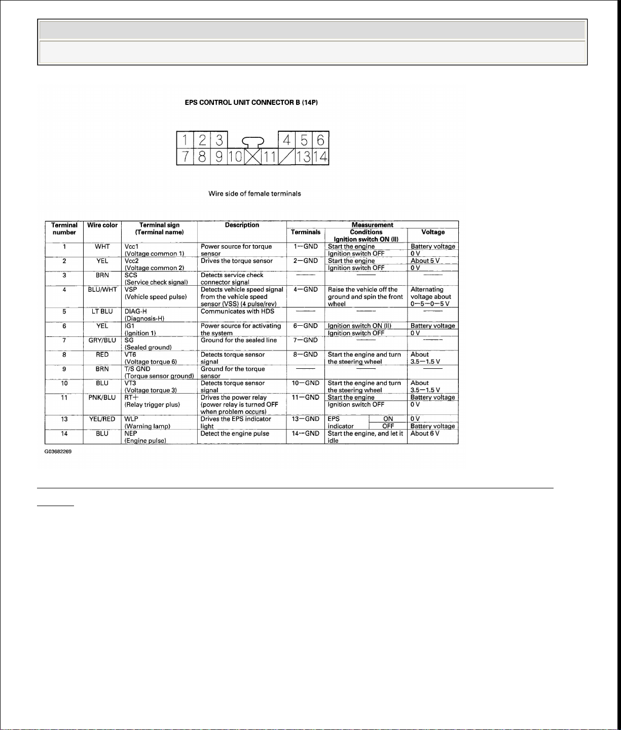
EPS CONTROL UNIT INPUTS AND OUTPUTS FOR CONNECTOR B (14P)
Page 16
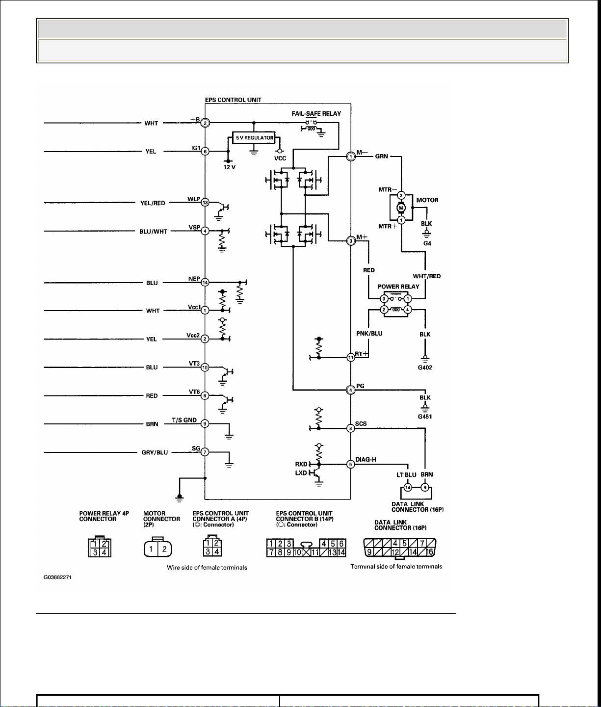
CIRCUIT DIAGRAM
2006 Honda Insight
2000-06 STEERING Electrical Power Steering (EPS) - Insight
Fig. 9: Identifying EPS Control Unit Inputs And Outputs For Connector B
(14P)
Courtesy of AMERICAN HONDA MOTOR CO., INC.
Page 17
2006 Honda Insight
2000-06 STEERING Electrical Power Steering (EPS) - Insight
Fig. 10: Identifying EPS Components Circuit Diagram (1 Of 2)
Courtesy of AMERICAN HONDA MOTOR CO., INC.
Page 18
2006 Honda Insight
2000-06 STEERING Electrical Power Steering (EPS) - Insight
Fig. 11: Identifying EPS Components Circuit Diagram (2 Of 2)
Courtesy of AMERICAN HONDA MOTOR CO., INC.
DTC TROUBLESHOOTING
DTC INDEX
Page 19
Does the EPS indicator come on?
EPS Control Unit Internal Circuit (Input
Motor Driven Current is Excessively
EPS Control Unit Internal Circuit (CPU
Battery Voltage is Excessively Low
safe Relay Contact Failure and
2006 Honda Insight
2000-06 STEERING Electrical Power Steering (EPS) - Insight
DTC Description
DTC 11 Torque Sensor VT3
DTC 15 Torque Sensor VT6
DTC 16 Torque Sensor VT3 and VT6
DTC 17 Torque Sensor Vcc1
DTC 18 Torque Sensor Vcc2
DTC 22 Vehicle Speed Sensor Signal
DTC 23 Engine Speed Signal
DTC 37
Circuit For Motor Voltage)
DTC 41 Voltage For Motor
DTC 42, 45 Motor Driven Current
DTC 43
High
DTC 46,47 Power Relay Stuck ON or Stuck OFF
DTC 50
or Microcomputer)
DTC 62 EPS Control Unit Internal Circuit (Fail-
safe Relay Stuck ON)
DTC 64
(Fail-
Motor Voltage Fall Off)
DTC 66 Motor Driven Voltage
DTC 67 Torque Sensor I/F Circuit
DTC 68 EPS Control Unit Internal Circuit
DTC 11: TORQUE SENSOR VT3; DTC 15: TORQUE SENSOR VT6; DTC 16: TORQUE SENSOR
VT3 AND VT6
1. Clear the DTC.
2. Start the engine.
3. Wait at least 10 seconds.
Page 20
EPS control unit connector B
2006 Honda Insight
2000-06 STEERING Electrical Power Steering (EPS) - Insight
YES -Go to step 4.
NO -Check for loose terminals or poor connections. If the connections are
good, the system is OK at this time.
4. Stop the engine, and verify the DTC.
Is DTC 11, DTC15 or DTC 16 indicated?
YES -Go to step 5.
NO -Do the appropriate troubleshooting for the code indicated.
5. Make sure the ignition switch is OFF, then disconnect the EPS control unit
connector B (14P) and the torque sensor 7P connector.
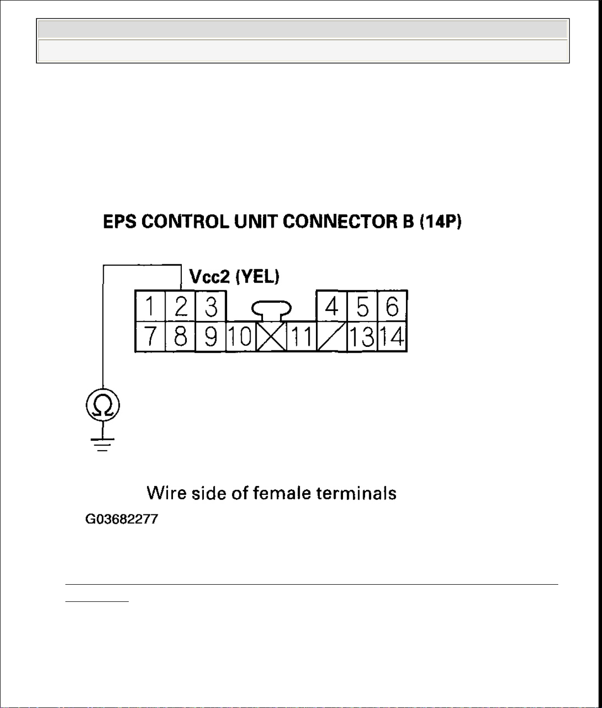
6. Check for continuity between the appropriate EPS control unit connector B
(14P) terminal and body ground (see table).
TERMINAL SPECIFICATION
Terminal name
terminal No.
Vcc1 1
Vcc2 2
VT3 10
VT6 8
T/S GND 9
Page 21
2006 Honda Insight
2000-06 STEERING Electrical Power Steering (EPS) - Insight
Fig. 12: Identifying EPS Control Unit Connector Terminal
Courtesy of AMERICAN HONDA MOTOR CO., INC.
Is there continuity?
YES -Repair short to body ground in the appropriate sensor circuit
between the torque sensor and EPS control unit.
NO -Go to step 7.
7. Turn the ignition switch ON (II).
8. Measure the voltage between the appropriate EPS control unit connector B
(14P) terminal and body ground (see table).
TERMINAL SPECIFICATION
Page 22
EPS control unit connector B
2006 Honda Insight
2000-06 STEERING Electrical Power Steering (EPS) - Insight
Terminal name
terminal No.
Vcc1 1
Vcc2 2
VT3 10
VT6 8
T/S GND 9
Fig. 13: Measuring Voltage Between Appropriate EPS Control Unit
Connector B
Courtesy of AMERICAN HONDA MOTOR CO., INC.
Page 23
Torque Sensor terminal
EPS control unit
connector B terminal
2006 Honda Insight
2000-06 STEERING Electrical Power Steering (EPS) - Insight
Is there battery voltage?
YES -Repair short to power in the (+) circuit wire between the EPS
control unit and torque sensor.
NO -Go to step 9.
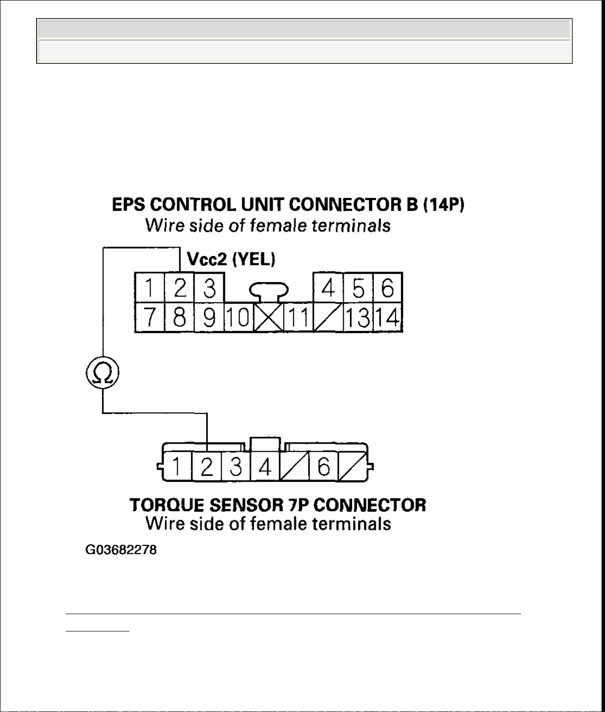
9. Turn the ignition switch OFF.
10. Check for continuity between the appropriate EPS control unit connector B
(14P) terminal and the torque sensor 7P connector terminal (see table).
TERMINAL SPECIFICATION
Terminal name
No.
Vcc1 6 1
No.
Vcc2 2 2
VT3 3 10
VT6 1 8
T/S GND 4 9
Page 24
-Go to step 10.
2006 Honda Insight
2000-06 STEERING Electrical Power Steering (EPS) - Insight
Fig. 14: Identifying EPS Control Unit Connector Terminal
Courtesy of AMERICAN HONDA MOTOR CO., INC.
Is there continuity?
YES
Page 25

-Go to step 5.
2006 Honda Insight
2000-06 STEERING Electrical Power Steering (EPS) - Insight
NO -Repair open in the appropriate torque sensor wire circuit between the
EPS control unit and the torque sensor.
11. Check for loose terminals or poor connections. If the connections are good,
substitute a known-good EPS control unit, and connect the all disconnected
connectors.
12. Start the engine.
Does the EPS indicator come on?
YES -Go to step 13.
NO -Check for poor connections or loose terminals at the EPS control
unit. If necessary, replace the EPS control unit and retest.
13. Stop the engine, and verify the DTC.
Is DTC11, DTC15 or DTC16 indicated?
YES -Check for poor connections or loose terminals at the torque sensor.
If necessary, substitute a known-good steering gearbox and recheck.
NO -Do the appropriate troubleshooting for the code indicated.
DTC 17: TORQUE SENSOR VCC1; DTC 18: TORQUE SENSOR VCC2
1. Clear the DTC.
2. Start the engine.
3. Wait at least 10 seconds.
Does the EPS indicator come on?
YES -Go to step 4.
NO -Check for loose terminals or poor connections. If the connections are
good, the system is OK at this time.
4. Stop the engine, and verify the DTC.
Is DTC17 or DTC18 indicated?
YES
Page 26
and EPS control unit.
2006 Honda Insight
2000-06 STEERING Electrical Power Steering (EPS) - Insight
NO -Do the appropriate troubleshooting for the code indicated.
5. Make sure the ignition switch is OFF, then disconnect the EPS control unit
connector B (14P) and torque sensor 7P connector.
6. Check for continuity between the EPS control unit connector B (14P) terminal
No. 1 and body ground.
Fig. 15: Identifying EPS Control Unit Connector
Courtesy of AMERICAN HONDA MOTOR CO., INC.
Is there continuity?
YES -Repair short to body ground in the wire between the torque sensor
Page 27
-Go to step 8.
2006 Honda Insight
2000-06 STEERING Electrical Power Steering (EPS) - Insight
NO -Go to step 7.
7. Check for continuity between the EPS control unit connector B (14P) terminal
No. 1 and the torque sensor 7P connector terminal No. 6.
Fig. 16: Identifying EPS Control Unit Connector Terminal
Courtesy of AMERICAN HONDA MOTOR CO., INC.
Is there continuity?
YES
Page 28
and EPS control unit.
2006 Honda Insight
2000-06 STEERING Electrical Power Steering (EPS) - Insight
NO -Repair open in the wire between the torque sensor and EPS control
unit.
8. Check for continuity between the EPS control unit connector B (14P) terminal
No. 2 and body ground.
Fig. 17: Checking Continuity Between EPS Control Unit Connector (14P)
Terminal
Courtesy of AMERICAN HONDA MOTOR CO., INC.
Is there continuity?
YES -Repair short to body ground in the wire between the torque sensor
Page 29
-Go to step 10.
2006 Honda Insight
2000-06 STEERING Electrical Power Steering (EPS) - Insight
NO -Go to step 9.
9. Check for continuity between the EPS control unit connector B (14P) terminal
No. 2 and the torque sensor 7P connector terminal No. 2.
Fig. 18: Checking Continuity Between EPS Control Unit Connector
Terminal
Courtesy of AMERICAN HONDA MOTOR CO., INC.
Is there continuity?
YES
Page 30

Is the tachometer working correctly?
2006 Honda Insight
2000-06 STEERING Electrical Power Steering (EPS) - Insight
NO -Repair open in the wire between the torque sensor and EPS control
unit.
10. Check for loose terminals or poor connections. If the connections are good,
substitute a known-good EPS control unit, and connect the all disconnected
connectors.
11. Start the engine.
Does the EPS indicator come on?
YES -Go to step 12.
NO -Check for poor connections or loose terminals at the EPS control
unit. If necessary, replace the EPS control unit and retest.
12. Stop the engine, and verify the DTC.
Is DTC17 or DTC18 indicated?
YES -Check for poor connections or loose terminals at the torque sensor.
If necessary, substitute a known-good steering gearbox and recheck.
NO -Do the appropriate troubleshooting for the code indicated.
DTC 22: VEHICLE SPEED SENSOR SIGNAL; DTC 23: ENGINE SPEED SIGNAL
NOTE:
If the MIL indicator is ON, troubleshoot the PGM-FI
system first.
When the engine is running at 2,000 RPM or above and
the vehicle speed is 1 mph (1 km/h) or below for 6
minutes the EPS indicator comes on.
When the vehicle speed is 6.2 mph (10 km/h) or more
and the engine is running at 280 RPM or below for 3
seconds, the EPS indicator comes on.
1. Start the engine and check the tachometer.
Page 31

VEHICLE SPEED
the voltage between the EPS control unit connector B (14P) terminal No. 4 and
body ground.
2006 Honda Insight
2000-06 STEERING Electrical Power Steering (EPS) - Insight
YES -Go to step 2.
NO -Go to step 9 .
2. Test-drive the vehicle above 9.3 mph (15 km/h).
Is the speedometer working correctly?
YES -Go to step 3.
NO -Do the speedometer system troubleshooting (see
SIGNAL CIRCUIT TROUBLESHOOTING ).
3. Block the rear wheels and raise the vehicle, and support it with safety stands in
the proper locations (see SAFETY STANDS ).
4. Turn the ignition switch ON (II).
5. Block the right front wheel, and slowly rotate the left front wheel, and measure
Page 32

Repair open in the wire between the EPS control unit and VSS. If the
wire is OK, check for a loose or poor connection at the EPS control unit. If
Turn the ignition switch OFF, and disconnect the EPS control unit connector B
(14P).
2006 Honda Insight
2000-06 STEERING Electrical Power Steering (EPS) - Insight
Fig. 19: Measuring Voltage Between EPS Control Unit Connector B (14P)
Terminal No. 4 And Body Ground
Courtesy of AMERICAN HONDA MOTOR CO., INC.
Does the voltage pulse 0 V and 5 V?
YES -Go to step 6.
NO -
necessary, substitute a known-good EPS control unit and recheck.
6.
Page 33

NO
-Repair open in the wire between the EPS control unit and the ECM.
2006 Honda Insight
2000-06 STEERING Electrical Power Steering (EPS) - Insight
7. Start the engine, and let it idle.
8. Measure the voltage between the EPS control unit connector B (14P) terminal
No.14 and body ground.
Fig. 20: Measuring Voltage Between EPS Control Unit Connector
Terminal
Courtesy of AMERICAN HONDA MOTOR CO., INC.
Is there about 6 V at idle?
YES -Check for poor connections or loose terminals at the EPS control
unit. If necessary, substitute a known-good EPS control unit and recheck.
Page 34

Turn the ignition switch OFF, and disconnect the EPS control unit connector B
-Check for poor connections or loose terminals at the EPS control
2006 Honda Insight
2000-06 STEERING Electrical Power Steering (EPS) - Insight
9.
(14P).
10. Start the engine, and let it idle.
11. Measure the voltage between the EPS control unit connector B (14P) terminal
IMo.14 and body ground.
Fig. 21: Measuring Voltage Between EPS Control Unit Connector
Terminal
Courtesy of AMERICAN HONDA MOTOR CO., INC.
Is there about 6 V at idle?
YES
Page 35

2006 Honda Insight
2000-06 STEERING Electrical Power Steering (EPS) - Insight
unit. If necessary, substitute a known-good EPS control unit and recheck.
NO -Go to step 12.
12. Turn the ignition switch OFF.
13. Disconnect the ECM connector A (32P).
14. Check for continuity between the EPS control unit connector B (14P) terminal
No.14 and the ECM connector A (32P) terminal No.19.
Page 36

Fig. 22: Checking Continuity At EPS Control Unit Connector B (14P)
Repair open in the BLU wire between the EPS control unit and ECM.
Courtesy of AMERICAN HONDA MOTOR CO., INC.
2006 Honda Insight
2000-06 STEERING Electrical Power Steering (EPS) - Insight
Courtesy of AMERICAN HONDA MOTOR CO., INC.
Is there continuity?
YES -Go to step 15.
NO -
15. Disconnect the gauge assembly 22P connector.
16. Check for continuity between the EPS control unit connector B (14P) terminal
No.14 and body ground.
Fig. 23: Checking Continuity At EPS Control Unit Connector B (14P)
Page 37

Does the EPS indicator come on?
2006 Honda Insight
2000-06 STEERING Electrical Power Steering (EPS) - Insight
Is there continuity?
YES -Repair short to body ground in the wire between the EPS control
unit, the test tachometer connector (see CIRCUIT DIAGRAM ), the
gauge assembly, and the ECM.
NO -Check for poor connections or loose terminals at the ECM. If
necessary, substitute a known-good ECM and recheck.
DTC 37: EPS CONTROL UNIT INTERNAL CIRCUIT (INPUT CIRCUIT FOR MOTOR VOLTAGE)
1. Clear the DTC.
2. Start the engine.
3. Turn the steering wheel from lock-to-lock several times, and wait 10 seconds
or more.
Does the EPS indicator come on?
YES -Go to step 4.
NO -Check for loose terminals or poor connections. If the connections are
good, the system is OK at this time.
4. Stop the engine, and verify the DTC.
Is DTC 37 indicated?
YES -Check for poor connections or loose terminals at the EPS control
unit. If necessary, substitute a known-good EPS control unit and recheck.
NO -Do the appropriate troubleshooting for the code indicated.
DTC 41: VOLTAGE FOR MOTOR
1. Clear the DTC.
2. Start the engine.
3. Turn the steering wheel from lock-to-lock several times, and wait 10 seconds
or more.
Page 38

No. 3 and body ground.
2006 Honda Insight
2000-06 STEERING Electrical Power Steering (EPS) - Insight
YES -Go to step 4.
NO -Check for loose terminals or poor connections. If the connections are
good, the system is OK at this time.
4. Stop the engine, and verify the DTC.
Is DTC 41 indicated?
YES -Go to step 5.
NO -Do the appropriate troubleshooting for the code indicated.
5. Make sure the ignition switch is OFF, then disconnect the EPS control unit
connector A (4P), power relay 4P connector, and motor connector (2P).
6. Check for continuity between the EPS control unit connector A (4P) terminal
Page 39

body ground.
2006 Honda Insight
2000-06 STEERING Electrical Power Steering (EPS) - Insight
Fig. 24: Checking Continuity Between EPS Control Unit Connector
Terminal And Body Ground
Courtesy of AMERICAN HONDA MOTOR CO., INC.
Is there continuity?
7. Check for continuity between the power relay 4P connector terminal No.1 and
YES -Repair short to body ground in the RED wire between the EPS
control unit and power relay.
NO -Go to step 7.
Page 40

motor and power relay.
2006 Honda Insight
2000-06 STEERING Electrical Power Steering (EPS) - Insight
Fig. 25: Checking Continuity Between Power Relay 4P Connector
Terminal And Body Ground
Courtesy of AMERICAN HONDA MOTOR CO., INC.
Is there continuity?
YES -Repair short to body ground in the WHT/RED wire between the
Page 41

control unit and motor.
2006 Honda Insight
2000-06 STEERING Electrical Power Steering (EPS) - Insight
NO -Go to step 8.
8. Check for continuity between the EPS control unit connector A (4P) terminal
No. 1 and body ground.
Fig. 26: Checking Between EPS Control Unit Connector A (4P) Terminal
No And Body Ground
Courtesy of AMERICAN HONDA MOTOR CO., INC.
Is there continuity?
YES -Repair short to body ground in the GRN wire between the EPS
Page 42

between the EPS control unit and motor.
2006 Honda Insight
2000-06 STEERING Electrical Power Steering (EPS) - Insight
NO -Go to step 9.
9. Check for continuity between the EPS control unit connector A (4P) terminal
No. 1 and No. 3.
Fig. 27: Checking Continuity Between EPS Control Unit Connector (4P)
Terminal
Courtesy of AMERICAN HONDA MOTOR CO., INC.
Is there continuity?
YES -Repair short between the RED and GRN wires in the motor circuit
Page 43

Fig. 28: Checking Continuity Between EPS Control Unit Connector A (4P)
Is there continuity?
2006 Honda Insight
2000-06 STEERING Electrical Power Steering (EPS) - Insight
NO -Go to step 10.
10. Check for continuity between the EPS control unit connector A (4P) terminal
No. 3 and the power relay 4P connector terminal No. 1.
Terminal No. 3
Courtesy of AMERICAN HONDA MOTOR CO., INC.
Page 44

2006 Honda Insight
2000-06 STEERING Electrical Power Steering (EPS) - Insight
YES -Repair short between the RED and WHT/RED wires in the motor
circuit between the EPS control unit and motor.
NO -Go to step 11.
11. Check for continuity between the EPS control unit connector A (4P) terminal
No. 1 and the power relay 4P connector terminal No. 1.
Page 45

Fig. 29: Checking Continuity Between EPS Control Unit Connector A (4P)
2006 Honda Insight
2000-06 STEERING Electrical Power Steering (EPS) - Insight
Terminal And Power Relay Connector Terminal
Courtesy of AMERICAN HONDA MOTOR CO., INC.
Is there continuity?
YES -Repair short between the GRN and WHT/RED wires in the motor
circuit between the EPS control unit and motor.
NO -Go to step 12.
12. Turn the ignition switch ON (II), and measure the voltage between the EPS
control unit connector A (4P) terminal No. 3 and body ground.
Page 46

Fig. 30: Identifying EPS Control Unit Connector
Repair short to power in the RED wire between the EPS control unit
2006 Honda Insight
2000-06 STEERING Electrical Power Steering (EPS) - Insight
Courtesy of AMERICAN HONDA MOTOR CO., INC.
Is there battery voltage?
YES and power relay.
NO -Go to step 13.
13. Measure the voltage between the EPS control unit connector A (4P) terminal
No. 1 and body ground.
Fig. 31: Measuring Voltage Between EPS Control Unit Connector A (4P)
Page 47

Terminal No And Body Ground
body ground.
2006 Honda Insight
2000-06 STEERING Electrical Power Steering (EPS) - Insight
Courtesy of AMERICAN HONDA MOTOR CO., INC.
Is there battery voltage?
YES -Repair short to power in the GRN wire between the EPS control
unit and motor.
NO -Go to step 14.
14. Measure the voltage between the power relay 4P connector terminal No. 1 and
Page 48

relay and motor.
2006 Honda Insight
2000-06 STEERING Electrical Power Steering (EPS) - Insight
Fig. 32: Measuring Voltage Between Power Relay 4P Connector Terminal
No And Body Ground
Courtesy of AMERICAN HONDA MOTOR CO., INC.
Is there battery voltage?
YES -Repair short to power in the WHT/RED wire between the power
Page 49

4.
Stop the engine, and verify the DTC.
2006 Honda Insight
2000-06 STEERING Electrical Power Steering (EPS) - Insight
NO -Go to step 15.
15. Turn the ignition switch is OFF.
16. Check for loose terminals or poor connections. If the connections are good,
substitute a known-good EPS control unit, and connect the all disconnected
connectors.
17. Start the engine.
Does the EPS indicator come on?
YES -Go to step 18.
NO -Check for poor connections or loose terminals at the EPS control
unit. If necessary, replace the EPS control unit and retest.
18. Stop the engine, and verify the DTC.
Is DTC 41 indicated?
YES -Check for poor connections or loose terminals at the EPS control
unit, motor, and the power relay. If necessary, substitute a known-good
steering gearbox and recheck.
NO -Do the appropriate troubleshooting for the code indicated.
DTC 42, 45: MOTOR DRIVEN CURRENT
1. Clear the DTC.
2. Start the engine.
3. Turn the steering wheel from lock-to-lock several times, and wait 10 seconds
or more.
Does the EPS indicator come on?
YES -Go to step 4.
NO -Check for loose terminals or poor connections. If the connections are
good, the system is OK at this time.
Page 50

2006 Honda Insight
2000-06 STEERING Electrical Power Steering (EPS) - Insight
Is DTC 42 or 45 indicated?
YES -Go to step 5.
NO -Do the appropriate troubleshooting for the code indicated.
5. Make sure the ignition switch is OFF, then disconnect the EPS control unit A
connector (4P), power relay 4P connector and motor connector (2P).
6. Check for continuity between the EPS control unit connector A (4P) terminal
No. 3 and body ground.
Fig. 33: Checking Continuity EPS Control Unit Connector A (4P)
Terminal And Body Ground
Page 51

Courtesy of AMERICAN HONDA MOTOR CO., INC.
body ground.
2006 Honda Insight
2000-06 STEERING Electrical Power Steering (EPS) - Insight
Is there continuity?
YES -Repair short to body ground in the RED wire between the EPS
control unit and power relay.
NO -Go to step 7.
7. Check for continuity between the power relay 4P connector terminal No. 1 and
Page 52

motor and power relay.
2006 Honda Insight
2000-06 STEERING Electrical Power Steering (EPS) - Insight
Fig. 34: Checking Continuity Between Power Relay 4P Connector
Terminal No And Body Ground
Courtesy of AMERICAN HONDA MOTOR CO., INC.
Is there continuity?
YES -Repair short to body ground in the WHT/RED wire between the
Page 53

Fig. 35: Checking Continuity Between EPS Control Unit Connector A (4P)
control unit and motor.
2006 Honda Insight
2000-06 STEERING Electrical Power Steering (EPS) - Insight
NO -Go to step 8.
8. Check for continuity between the EPS control unit connector A (4P) terminal
No. 1 and body ground.
Terminal And Body Ground
Courtesy of AMERICAN HONDA MOTOR CO., INC.
Is there continuity?
YES -Repair short to body ground in the GRN wire between the EPS
Page 54

Fig. 36: Checking Continuity Between EPS Control Unit Connector A (4P)
-Repair short between the RED and GRN wires in the motor circuit
2006 Honda Insight
2000-06 STEERING Electrical Power Steering (EPS) - Insight
NO -Go to step 9.
9. Check for continuity between the EPS control unit connector A (4P) terminal
No. 1 and No. 3.
Terminal
Courtesy of AMERICAN HONDA MOTOR CO., INC.
Is there continuity?
YES
Page 55

Fig. 37: Checking Continuity Between EPS Control Unit Connector A (4P)
Courtesy of AMERICAN HONDA MOTOR CO., INC.
2006 Honda Insight
2000-06 STEERING Electrical Power Steering (EPS) - Insight
between the EPS control unit and motor.
NO -Go to step 10.
10. Check for continuity between the EPS control unit connector A (4P) terminal
No. 3 and the power relay 4P connector terminal No. 1.
Terminal
Page 56

No. 1 and the power relay 4P connector terminal No. 1.
2006 Honda Insight
2000-06 STEERING Electrical Power Steering (EPS) - Insight
Is there continuity?
YES -Repair short between the RED and WHT/RED wires in the motor
circuit between the EPS control unit and motor.
NO -Go to step 11.
11. Check for continuity between the EPS control unit connector A (4P) terminal
Page 57

Fig. 38: Checking Continuity Between EPS Control Unit Connector A (4P)
Is there continuity?
2006 Honda Insight
2000-06 STEERING Electrical Power Steering (EPS) - Insight
Terminal
Courtesy of AMERICAN HONDA MOTOR CO., INC.
Page 58

Is there battery voltage?
2006 Honda Insight
2000-06 STEERING Electrical Power Steering (EPS) - Insight
YES -Repair short between the GRN and WHT/RED wires in the motor
circuit between the EPS control unit and motor.
NO -Go to step 12.
12. Turn the ignition switch ON (II), and measure the voltage between the EPS
control unit connector A (4P) terminal No. 3 and body ground.
Fig. 39: Identifying EPS Control Unit Connector
Courtesy of AMERICAN HONDA MOTOR CO., INC.
Page 59

Is there battery voltage?
2006 Honda Insight
2000-06 STEERING Electrical Power Steering (EPS) - Insight
YES -Repair short to power in the (+) circuit wire between the EPS
control unit and power relay.
NO -Go to step 13.
13. Measure the voltage between the EPS control unit connector A (4P) terminal
No. 1 and body ground.
Fig. 40: Measuring Voltage Between EPS Control Unit Connector A (4P)
Terminal And Body Ground
Courtesy of AMERICAN HONDA MOTOR CO., INC.
Page 60

2006 Honda Insight
2000-06 STEERING Electrical Power Steering (EPS) - Insight
YES -Repair short to power in the (+) circuit wire between the EPS
control unit and motor.
NO -Go to step 14.
14. Measure the voltage between the power relay 4P connector terminal No. 1 and
body ground.
Fig. 41: Measuring Voltage Between Power Relay 4P Connector Terminal
Page 61

And Body Ground
Turn the ignition switch OFF and check for continuity between the EPS control
terminal No. 3.
2006 Honda Insight
2000-06 STEERING Electrical Power Steering (EPS) - Insight
Courtesy of AMERICAN HONDA MOTOR CO., INC.
Is there battery voltage?
YES -Repair short to power in the (+) circuit wire between the power
relay and motor.
NO -Go to step 15.
15.
unit connector A (4P) terminal No. 3 and the power relay 4P connector
Page 62

Fig. 42: Checking Continuity Between EPS Control Unit Connector A (4P)
Is there continuity?
2006 Honda Insight
2000-06 STEERING Electrical Power Steering (EPS) - Insight
Terminal
Courtesy of AMERICAN HONDA MOTOR CO., INC.
Page 63

the motor connector (2P) terminal No. 1.
2006 Honda Insight
2000-06 STEERING Electrical Power Steering (EPS) - Insight
YES -Go to step 16.
NO -Repair open in the RED wire between the EPS control unit and
motor.
16. Check for continuity between the power relay 4P connector terminal No. 1 and
Page 64

2006 Honda Insight
2000-06 STEERING Electrical Power Steering (EPS) - Insight
Fig. 43: Checking Continuity Between Power Relay 4P Connector
Terminal
Page 65

Courtesy of AMERICAN HONDA MOTOR CO., INC.
No. 1 and the motor connector (2P) terminal No. 2.
2006 Honda Insight
2000-06 STEERING Electrical Power Steering (EPS) - Insight
Is there continuity?
YES -Go to step 17.
NO -Repair open in the WHT/RED wire between the motor and power
relay.
17. Check for continuity between the EPS control unit connector A (4P) terminal
Page 66

Fig. 44: Checking Continuity Between EPS Control Unit Connector A (4P)
-Go to step 18.
2006 Honda Insight
2000-06 STEERING Electrical Power Steering (EPS) - Insight
Terminal
Courtesy of AMERICAN HONDA MOTOR CO., INC.
Is there continuity?
YES
Page 67

Is DTC 43 indicated?
2006 Honda Insight
2000-06 STEERING Electrical Power Steering (EPS) - Insight
NO -Repair open in the GRN wire between the EPS control unit and
motor.
18. Substitute a known-good EPS control unit, and connect the all disconnected
connectors.
19. Start the engine.
Does the EPS indicator come on?
YES -Go to step 20.
NO -Check for poor connections or loose terminals at the EPS control
unit. If necessary, replace the EPS control unit and retest.
20. Stop the engine, and verify the DTC.
Is DTC 42 or 45 indicated?
YES -Check for poor connections or loose terminals at the EPS control
unit, motor, and the power relay. If necessary, substitute a known-good
steering gearbox and recheck.
NO -Do the appropriate troubleshooting for the code indicated.
DTC 43: MOTOR DRIVEN CURRENT IS EXCESSIVELY HIGH
1. Clear the DTC.
2. Start the engine.
3. Turn the steering wheel from lock-to-lock several times, and wait 10 seconds
or more.
Does the EPS indicator come on?
YES -Go to step 4.
NO -Check for loose terminals or poor connections. If the connections are
good, the system is OK at this time.
4. Stop the engine, and verify the DTC.
Page 68

2006 Honda Insight
2000-06 STEERING Electrical Power Steering (EPS) - Insight
YES -Go to step 5.
NO -Do the appropriate troubleshooting for the code indicated.
5. Make sure the ignition switch is OFF, then disconnect the EPS control unit
connector A (4P), the power relay 4P connector, and the motor connector (2P).
6. Turn the ignition switch ON (II).
7. Measure the voltage between the EPS control unit connector A (4P) terminal
No. 3 and body ground.
Fig. 45: Measuring Voltage Between EPS Control Unit Connector A (4P)
Terminal No. 3 And Body Ground
Courtesy of AMERICAN HONDA MOTOR CO., INC.
Page 69

2006 Honda Insight
2000-06 STEERING Electrical Power Steering (EPS) - Insight
Is there battery voltage?
YES -Repair short to power in the (+) circuit wire between the EPS
control unit and power relay.
NO -Go to step 8.
8. Measure the voltage between the EPS control unit connector A (4P) terminal
No. 1 and body ground.
Fig. 46: Measuring Voltage Between EPS Control Unit Connector A (4P)
Terminal No And Body Ground
Courtesy of AMERICAN HONDA MOTOR CO., INC.
Page 70

body ground.
2006 Honda Insight
2000-06 STEERING Electrical Power Steering (EPS) - Insight
Is there battery voltage?
YES -Repair short to power in the - circuit wire between the EPS control
unit and motor.
NO -Go to step 9.
9. Measure the voltage between the power relay 4P connector terminal No. 1 and
Page 71

relay and motor.
2006 Honda Insight
2000-06 STEERING Electrical Power Steering (EPS) - Insight
Fig. 47: Measuring Voltage Between Power Relay 4P Connector Terminal
No And Body Ground
Courtesy of AMERICAN HONDA MOTOR CO., INC.
Is there battery voltage ?
YES -Repair short to power in the (+) circuit wire between the power
Page 72

Fig. 48: Checking Continuity Between EPS Control Unit Connector A (4P)
Is there continuity ?
2006 Honda Insight
2000-06 STEERING Electrical Power Steering (EPS) - Insight
NO -Go to step 10.
10. Turn the ignition switch is OFF.
11. Check for continuity between the EPS control unit connector A (4P) terminal
No. 1 and No. 3.
Terminal
Courtesy of AMERICAN HONDA MOTOR CO., INC.
Page 73

Fig. 49: Checking Continuity Between EPS Control Unit Connector A (4P)
2006 Honda Insight
2000-06 STEERING Electrical Power Steering (EPS) - Insight
YES -Repair short between the GRN and RED wires in the motor circuit
between the EPS control unit and motor.
NO -Go to step 12.
12. Check for continuity between the EPS control unit connector A (4P) terminal
No. 3 and the power relay 4P connector terminal No. 1.
Terminal
Page 74

Courtesy of AMERICAN HONDA MOTOR CO., INC.
No. 1 and the power relay 4P connector terminal No. 1.
2006 Honda Insight
2000-06 STEERING Electrical Power Steering (EPS) - Insight
Is there continuity ?
YES -Repair short between the RED and WHT/RED wires in the motor
circuit between the EPS control unit and motor.
NO -Go to step 13.
13. Check for continuity between the EPS control unit connector A (4P) terminal
Page 75

Fig. 50: Checking Continuity Between EPS Control Unit Connector A (4P)
Is there continuity ?
2006 Honda Insight
2000-06 STEERING Electrical Power Steering (EPS) - Insight
Terminal
Courtesy of AMERICAN HONDA MOTOR CO., INC.
Page 76

-Go to step 4.
2006 Honda Insight
2000-06 STEERING Electrical Power Steering (EPS) - Insight
YES -Repair short between the GRN and WHT/RED wires in the motor
circuit between the EPS control unit and motor.
NO -Go to step 14.
14. Substitute a known-good EPS control unit, and connect the all disconnected
connectors.
15. Start the engine.
Does the EPS indicator come on ?
YES -Go to step 16.
NO -Check for poor connections or loose terminals at the EPS control
unit. If necessary, replace the EPS control unit and retest.
16. Stop the engine, and verify the DTC.
Is DTC 43 indicated ?
YES -Check for poor connections or loose terminals at the EPS control
unit, motor, and the power relay. If necessary, substitute a known-good
steering gearbox and recheck.
NO -Do the appropriate troubleshooting for the code indicated.
DTC 46,47: POWER RELAY STUCK ON OR STUCK OFF
1. Clear the DTC.
2. Start the engine.
Does the EPS indicator come on ?
YES -Go to step 3.
NO -Check for loose terminals or poor connections. If the connections are
good, the system is OK at this time.
3. Stop the engine, and verify the DTC.
Is DTC 46 or 47 indicated ?
YES
Page 77

No. 3 and the power relay 4P connector terminal No. 3.
2006 Honda Insight
2000-06 STEERING Electrical Power Steering (EPS) - Insight
NO -Do the appropriate troubleshooting for the code indicated.
4. Make sure the ignition switch is OFF, then remove the power relay and test it
(see POWER RELAY TEST ).
Is the relay OK ?
YES -With the power relay removed, go to step 5.
NO -Replace the power relay.
5. Disconnect the EPS control unit connector A (4P).
6. Check for continuity between the EPS control unit connector A (4P) terminal
Page 78

Fig. 51: Checking Continuity Between EPS Control Unit Connector A (4P)
Is there continuity ?
2006 Honda Insight
2000-06 STEERING Electrical Power Steering (EPS) - Insight
Terminal No And Power Relay 4P Connector Terminal
Courtesy of AMERICAN HONDA MOTOR CO., INC.
Page 79

motor connector (2P) terminal No. 1.
2006 Honda Insight
2000-06 STEERING Electrical Power Steering (EPS) - Insight
YES -Go to step 7.
NO -Repair open in the RED wire between the EPS control unit and
power relay.
7. Disconnect the motor connector (2P).
8. Check for continuity between the power relay 4P connector terminal No. 1 and
Page 80

Fig. 52: Disconnecting Motor Connector (2P)
2006 Honda Insight
2000-06 STEERING Electrical Power Steering (EPS) - Insight
Page 81

Courtesy of AMERICAN HONDA MOTOR CO., INC.
body ground.
2006 Honda Insight
2000-06 STEERING Electrical Power Steering (EPS) - Insight
Is there continuity ?
YES -Go to step 9.
NO -Repair open in the WHT/RED wire between the motor and power
relay.
9. Turn the ignition switch ON (II).
10. Measure the voltage between the power relay 4P connector terminal No. 1 and
Page 82

-Repair short to power in the WHT/RED wire between the power
2006 Honda Insight
2000-06 STEERING Electrical Power Steering (EPS) - Insight
Fig. 53: Measuring Voltage Between Power Relay 4P Connector Terminal
No And Body Ground
Courtesy of AMERICAN HONDA MOTOR CO., INC.
Is there battery voltage ?
YES
Page 83

Fig. 54: Measuring Voltage Between Power Relay 4P Connector Terminal
2006 Honda Insight
2000-06 STEERING Electrical Power Steering (EPS) - Insight
relay and motor.
NO -Go to step 11.
11. Measure the voltage between the power relay 4P connector terminal No. 3 and
body ground.
Page 84

And Body Ground
body ground.
2006 Honda Insight
2000-06 STEERING Electrical Power Steering (EPS) - Insight
Courtesy of AMERICAN HONDA MOTOR CO., INC.
Is there battery voltage ?
YES -Repair short to power in the RED wire between the power relay and
motor.
NO -Go to step 12.
12. Turn the ignition switch OFF.
13. Check for continuity between the power relay 4P connector terminal No. 3 and
Page 85

-Repair short to body ground in the RED wire between the EPS
2006 Honda Insight
2000-06 STEERING Electrical Power Steering (EPS) - Insight
Fig. 55: Checking Continuity Between Power Relay 4P Connector
Terminal No And Body Ground
Courtesy of AMERICAN HONDA MOTOR CO., INC.
Is there continuity ?
YES
Page 86

2006 Honda Insight
2000-06 STEERING Electrical Power Steering (EPS) - Insight
control unit and power relay.
NO -Go to step 14.
14. Check for continuity between the power relay 4P connector terminal No. 1 and
body ground.
Fig. 56: Checking Continuity Between Power Relay 4P Connector
Terminal No And Body Ground
Page 87

Courtesy of AMERICAN HONDA MOTOR CO., INC.
body ground.
2006 Honda Insight
2000-06 STEERING Electrical Power Steering (EPS) - Insight
Is there continuity ?
YES -Repair short to body ground in the WHT/RED wire between the
motor and power relay.
NO -Go to step 15.
15. Start the engine.
16. Measure the voltage between the power relay 4P connector terminal No. 2 and
Page 88

-Go to step 17.
2006 Honda Insight
2000-06 STEERING Electrical Power Steering (EPS) - Insight
Fig. 57: Measuring Voltage Between Power Relay 4P Connector Terminal
And Body Ground
Courtesy of AMERICAN HONDA MOTOR CO., INC.
Is there battery voltage ?
YES
Page 89

body ground.
2006 Honda Insight
2000-06 STEERING Electrical Power Steering (EPS) - Insight
NO -Repair short or open in the PNK/BLU wire between the EPS control
unit and power relay.
17. Turn the ignition switch OFF.
18. Disconnect the EPS control unit connector B (14P).
19. Start the engine.
20. Measure the voltage between the power relay 4P connector terminal No. 2 and
Page 90

-Repair short to power in the PNK/BLU wire between the EPS
2006 Honda Insight
2000-06 STEERING Electrical Power Steering (EPS) - Insight
Fig. 58: Measuring Voltage Between Power Relay 4P Connector Terminal
And Body Ground
Courtesy of AMERICAN HONDA MOTOR CO., INC.
Is there battery voltage ?
YES
Page 91

2006 Honda Insight
2000-06 STEERING Electrical Power Steering (EPS) - Insight
control unit and power relay.
NO -Go to step 21.
21. Turn the ignition switch OFF.
22. Check for continuity between the power relay 4P connector terminal No. 2 and
body ground.
Page 92

Fig. 59: Checking Continuity Between Power Relay 4P Connector
Repair short to body ground in the PNK/BLU wire between the EPS
body ground.
2006 Honda Insight
2000-06 STEERING Electrical Power Steering (EPS) - Insight
Terminal And Body Ground
Courtesy of AMERICAN HONDA MOTOR CO., INC.
Is there continuity ?
YES control unit and power relay.
NO -Go to step 23.
23. Check for continuity between the power relay 4P connector terminal No. 4 and
Page 93

-Check for poor connections or loose terminals at the EPS control
2006 Honda Insight
2000-06 STEERING Electrical Power Steering (EPS) - Insight
Fig. 60: Checking Continuity Between Power Relay 4P Connector
Terminal And Body Ground
Courtesy of AMERICAN HONDA MOTOR CO., INC.
Is there continuity ?
YES
Page 94

Is DTC 62 indicated ?
2006 Honda Insight
2000-06 STEERING Electrical Power Steering (EPS) - Insight
unit, motor, and the power relay. If necessary, substitute a known-good
EPS control unit and recheck.
NO -Repair open in the BLK wire between the power relay and body
ground (G402).
DTC 50: EPS CONTROL UNIT INTERNAL CIRCUIT (CPU OR MICROCOMPUTER)
1. Clear the DTC.
2. Start the engine.
Does the EPS indicator come on ?
YES -Go to step 3.
NO -Check for loose terminals or poor connections. If the connections are
good, the system is OK at this time.
3. Stop the engine, and verify the DTC.
Is DTC 50 indicated ?
YES -Check for poor connections or loose terminals at the EPS control
unit. If necessary, substitute a known-good EPS control unit and recheck.
NO -Do the appropriate troubleshooting for the code indicated.
DTC 62: EPS CONTROL UNIT INTERNAL CIRCUIT (FAIL-SAFE RELAY STUCK ON)
1. Clear the DTC.
2. Start the engine.
Does the EPS indicator come on ?
YES -Go to step 3.
NO -Check for loose terminals or poor connections If the connections are
good, the system is OK at this time.
3. Stop the engine, and verify the DTC.
Page 95

SAFE RELAY CONTACT FAILURE
No. 2 and body ground.
2006 Honda Insight
2000-06 STEERING Electrical Power Steering (EPS) - Insight
YES -Check for loose or poor connections at the EPS control unit. If the
connections are good, substitute a known-good EPS control unit. If the
symptom/indication goes away, replace the original EPS control unit and
recheck.
NO -Do the appropriate troubleshooting for the code indicated.
DTC 64: BATTERY VOLTAGE IS EXCESSIVELY LOW (FAILAND MOTOR VOLTAGE FALL OFF)
1. Clear the DTC.
2. Start the engine.
Does the EPS indicator come on ?
YES -Go to step 3.
NO -Check for loose terminals or poor connections. If the connections are
good, the system is OK at this time.
3. Stop the engine, and verify the DTC.
Is DTC 64 indicated ?
YES -Go to step 4.
NO -Do the appropriate troubleshooting for the code indicated.
4. Check the No. 15 (40 A) fuse in the under-hood fuse/relay box, and reinstall
the fuse if it is OK.
Is the fuse OK ?
YES -Go to step 5.
NO -Replace the fuse and recheck.
5. Disconnect the EPS control unit connector A (4P).
6. Measure the voltage between the EPS control unit connector A (4P) terminal
Page 96

under
-
hood fuse/relay box and EPS control unit.
2006 Honda Insight
2000-06 STEERING Electrical Power Steering (EPS) - Insight
Fig. 61: Measuring Voltage Between EPS Control Unit Connector A (4P)
Terminal No And Body Ground
Courtesy of AMERICAN HONDA MOTOR CO., INC.
Is there battery voltage ?
YES -Check for loose or poor connections at the EPS control unit. If the
connections are good, substitute a known-good EPS control unit. If the
symptom/indication goes away, replace the original EPS control unit and
recheck.
NO -Repair open in the WHT wire between the No. 15 (40 A) fuse in the
Page 97

DTC 66: MOTOR DRIVEN VOLTAGE; DTC 68: EPS CONTROL UNIT INTERNAL CIRCUIT
4.
Stop the engine, and verify the DTC.
2006 Honda Insight
2000-06 STEERING Electrical Power Steering (EPS) - Insight
1. Clear the DTC.
2. Start the engine.
3. Turn the steering terminals from lock-to-lock several times, and wait 10
seconds or more.
Does the EPS indicator come on ?
YES -Go to step 4.
NO -Check for loose terminals or poor connections. If the connections are
good, the system is OK at this time.
4. Stop the engine, and verify the DTC.
Is DTC 66 or 68 indicated ?
YES -Check for loose or poor connections at the EPS control unit. If the
connections are good, substitute a known-good EPS control unit. If the
symptom/indication goes away, replace the original EPS control unit and
recheck.
NO -Do the appropriate troubleshooting for the code indicated.
DTC 67: TORQUE SENSOR I/F CIRCUIT
1. Clear the DTC.
2. Start the engine.
3. Turn the steering wheel from lock-to-lock several time, and wait 10 seconds or
more.
Does the EPS Indicator come on ?
YES -Go to step 4.
NO -Check for loose terminals or poor connections. If the connections are
good, the system is OK at this time.
Page 98

No. 2 and body ground, then turn the ignition switch ON (II).
2006 Honda Insight
2000-06 STEERING Electrical Power Steering (EPS) - Insight
Is DTC 67 indicated ?
YES -Check for loose or poor connections at the EPS control unit. If the
connections are good, substitute a known-good EPS control unit. If the
symptom/indication goes away, replace the original EPS control unit and
recheck.
NO -Do the appropriate troubleshooting for the code indicated.
EPS INDICATOR CIRCUIT TROUBLESHOOTING
1. Turn the ignition switch ON (II), start the engine, and watch the EPS indicator.
Does the EPS indicator come on ?
YES -If the EPS indicator comes on and goes off, it's OK. If the EPS
indicator stays on or blinks, go to step 9 .
NO -Go to step 2.
2. Turn the ignition switch OFF, then ON (II) again, and watch the brake system
indicator.
Does the brake system indicator come on ?
YES -Go to step 3.
NO -Repair open in the indicator power source circuit:
Blown No. 6 (7.5 A) fuse in the under-dash fuse/ relay box.
Open in the wire between the No. 6 (7.5 A) fuse and gauge assembly.
Open circuit inside the under-dash fuse/relay box.
3. Turn the ignition switch OFF.
4. Connect a jumper wire between the gauge assembly 22P connector terminal
Page 99

ground with a jumper wire.
2006 Honda Insight
2000-06 STEERING Electrical Power Steering (EPS) - Insight
Fig. 62: Connecting Jumper Wire Between Gauge Assembly 22P
Connector Terminal No. 2 And Body Ground
Courtesy of AMERICAN HONDA MOTOR CO., INC.
Does EPS indicator come on ?
YES -Go to step 5.
NO -Inspect the EPS indicator bulb, if the bulb is OK, replace the gauge
assembly (see VSS REPLACEMENT ).
5. Turn the ignition switch OFF.
6. Disconnect the EPS control unit connector B (14P).
7. Turn the ignition switch ON (II).
8. Connect the EPS control unit connector B (14P) terminal No. 13 to body
Page 100

Repair open in the wire between the gauge assembly and EPS control
10.
Disconnect the EPS control unit connector B (14P).
2006 Honda Insight
2000-06 STEERING Electrical Power Steering (EPS) - Insight
Fig. 63: Connecting EPS Control Unit Connector B (14P) Terminal No. 13
To Body Ground With A Jumper Wire
Courtesy of AMERICAN HONDA MOTOR CO., INC.
Does EPS indicator come on ?
YES -Check for loose or poor connections at the EPS control unit. If the
connections are good, substitute a known-good EPS control unit. If the
symptom/indication goes away, replace the original EPS control unit and
recheck.
NO unit.
9. Turn the ignition switch OFF.
 Loading...