

Page 1

13/02/07 11:38:50 32MJG600_001
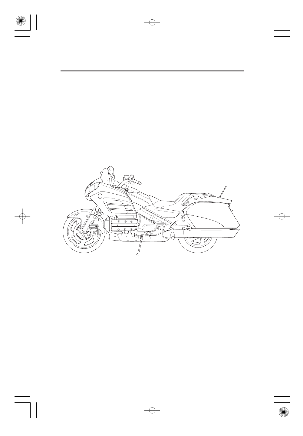
Honda GOLDWING F6B
OWNER’S MANUAL
USO E MANUTENZIONE
MANUAL DEL PROPIETARIO
Honda Motor Co., Ltd. 2013
Page 2

12/12/06 16:11:11 32MJG600_002
IMPORTANT INFORMA TION
OPERATOR AND PASSENGER
(Except KO, SI type)
This motorcycle is designed to carry the operator and one passenger. Never
exceed the maximum weight capacity as shown on the accessories and
loading label.
(KO, SI type)
This motorcycle is designed to carry the operator and one passenger. Never
exceed the maximum weight capacity.
ON-ROAD USE
This motorcycle is designed to be used only on the road.
READ THIS OWNER’S MANUAL CAREFULLY
Pay special attention to the safety messages that appear throughout the
manual. These messages are fully explained in the ‘‘A Few Words About
Safety’’ section which appears before the ‘‘Contents’’ page.
This manual should be considered a permanent part of the motorcycle and
should remain with the motorcycle when resold.
Page 3
13/02/07 11:38:54 32MJG600_003
Honda GOLDWING F6B
OWNER’S MANUAL
All inf ormation in this publication is based on the latest production
information available at the time of approval f or printing. Honda Motor
Co., Ltd. reserves the right to make changes at any time without notice
and without incurring any obligation.
No part of this publication may be reproduced without written
permission.
Page 4
12/12/06 16:11:18 32MJG600_004
WELCOME
The motorcycle presents you a challenge to master the machine, a challenge to
adventure. You ride through the wind, linked to the road by a vehicle that
responds to your commands as no other does. Unlike an automobile, there is
no metal cage around you. Like an airplane, a pre-ride inspection and regular
maintenance are essential to your safety. Your reward is freedom.
To meet the challenges safely, and to enjoy the adventure fully, you should
become thoroughly familiar with this owner’s manual BEFORE YOU RIDE
THE MOTORCYCLE.
Asyoureadthismanual,youwillfindinformationthatisprecededbya
symbol. T his information is intended to help you avoid damage to
your motorcycle, other property, or the environment.
Pleasant riding, and thank you for choosing a Honda !
Page 5
12/12/06 16:11:26 32MJG600_005
The f ollowing codes in this manual indicate each country.
UKE
F
ED
KO
U
SI
France
European direct sales
Korea
Australia New Zealand
Singapore
The specifications may vary with each locale.
The illustrations herein are based on the type.
This vehicle pictured in this owner’s manual may not match your actual
vehicle.
ED
Page 6
12/12/06 16:11:30 32MJG600_006
AFEWWORDSABOUTSAFETY
Your safety, and the safety of others, is very important. And operating this
motorcycle safely is an important responsibility.
To help you make informed decisions about safety, we have provided operating
procedures and other information on labels and in this manual. This
information alerts you to potential hazards that could hurt you or others.
Of course, it is not practical or possible to warn you about all hazards
associated with operating or maintaining a motorcycle. You must use your own
good judgment.
You will f ind important safety information in a variety of forms, including:
Safety Labels
Safety Messages
signal words: or .
These signal words mean:
–– on the motorcycle.
–– preceded by a safety alert symbol and one of three
DANGER, WARNING, CAUTION
Page 7
12/12/06 16:11:34 32MJG600_007
You WILL be KILLED or SERIOUSLY HURT if
you don’t follow instructions.
You CAN be KILLED or SERIOUSLY HURT if
you don’t follow instructions.
You CAN be HURT if you don’t follow
instructions.
Safety Headings
–– such as Important Safety Reminders or Important
Safety Precautions.
Safety Section
Instruct ions
–– such as Motorcycle Safety.
–– how to use this motorcycle correctly and safely.
This entire manual is f illed with important safety inf ormation –– please read it
carefully.
Page 8

12/12/06 16:11:50 32MJG600_008
CONTENTS
OPERATION
Page
MOTORCYCLE SAFETY
1
1
IMPORTANT SAFET Y INFORMATION
2
PROTECTIVE APPAREL
4
LOAD LIMITS AND GUIDELINES
8
IMAGE LABELS
17
SAFETY LABELS
PARTS LOCA TION
20
23
INSTRUMENTS AND INDICAT ORS
28
MULTI INFORMATION DISPLAY
36
MAJOR COMPONENTS
(Information you need to operate this motorcycle)
36
REAR SUSPENSION
37
BRAKES
40
CLUTCH
42
COOLANT
44
FUEL
47
ENGINE OIL
48
TUBELESS TYRES
53
ESSENTIA L INDIVIDUA L COMPONENTS
53
IGNITION SWITCH
54
KEYS
55
IMMOBILIZER SYSTEM (HISS)
58
RIGHT HANDLEBAR CONTROLS
59
LEFT HANDLEBAR CONTROLS
Page 9
12/12/06 16:12:02 32MJG600_009
Page
FEATURES
60
(Not required for operation)
STEERING LOCK
60
HELMET HOLDER
60
SADDLEBAGS
61
FAIRING POCKET/SHELTER CASE
63
DOCUMENTS
64
HEADLIGHT AIM VERTICAL ADJUSTMENT
65
ACC TERMINAL
66
AUDIO SYSTEMS
67
RADIO
83
AUXILIARY FUNCTION
99
iPod
101
115
OPERATION
118
118
119
122
123
124
127
128
/USB FLASH DRIVE
INTERCOM (I-COM) SYST EM
PRE-RIDE INSPECTION
STARTING THE ENGINE
RUNNING-IN
RIDING
BRAKING
PARKING
ANTI-THEFT TIPS
Page 10

12/12/06 16:12:20 32MJG600_010
CONTENTS
MAINT ENANCE
Page
MAINT ENANCE
129
129
THE IMPORTANCE OF MAINTENANCE
130
MAINTENANCE SAFETY
131
SAFETY PRECAUTIONS
132
MAINTENANCE SCHEDULE
134
TOOL KIT
135
SERIAL NUMBERS
136
COLOUR LABEL
137
COVER REMOVAL
142
CLIP
143
ENGINE OIL
148
CRANKCASE BREATHER
149
SPARK PLUGS
151
COOLANT
152
FRONT AND REAR SUSPENSION INSPECTION
153
SIDE STAND
154
WHEEL REMOVAL
162
BRAKE PAD WEAR
163
BRAKE SYSTEM INSPECTION
164
BATTERY
166
FUSE REPLACEMENT
168
BULB REPLACEMENT
CLEA NING
175
STORAGE GUIDE
179
179
STORAGE
180
REMOVAL FROM STORAGE
TAKING CARE OF THE UNEXPECTED
181
SPECIFICATIONS
182
CATALYTIC CONVERTER
185
Page 11

12/12/06 16:12:30 32MJG600_011
MOTORCYCLE SAFETY
IMPORTANT SAFETY INFORMATION
responsibility for your own safety and understand the challenges that you can
meet on the road.
There is much that you can do to protect yourself when you ride. You’ll f ind
many helpf ul recommendations throughout this manual. Following are a few
that we consider to be most important.
Always Wear a Helmet
It’s a proven fact: helmets significantly reduce the number and severity of head
injuries. So always wear an approved motorcycle helmet and make sure your
passenger does the same. We also recommend that you wear eye protection,
sturdy boots, gloves, and other protective gear (page ).2
Make Yourself Easy to See
Some drivers do not see motorcycles because they are not looking for them.
To make yourself more visible, wear bright reflective clothing, position
yourself so other drivers can see you, signal before turning or changing lanes,
and use your horn when it will help others notice you.
−Your motorcycle can provide many years of service and pleasure if you take
Ride Within Your Limits
Pushing the limits is another major cause of motorcycle crashes. Never ride
beyond your personal abilities or faster than conditions warrant. Remember
that alcohol, drugs, fatigue and inattention can significantly reduce your ability
to make good judgements and ride safely.
Don’t Drink and Ride
Alcohol and riding don’t mix. Even one drink can reduce your ability to respond
to changing conditions, and your reaction time gets worse with every additional
drink. So don’t drink and ride, and don’t let your friends drink and ride either.
Keep Your Bike in Saf e Condition
For safe riding, it’s important to inspect your motorcycle bef ore every ride and
perform all recommended maintenance. Never exceed load limits, and only use
accessories that have been approved by Honda for this motorcycle. See page
4
for more details.
1
Page 12
12/12/06 16:12:35 32MJG600_012
MOTORCYCLE SAFETY
PROTECTIVE APPAREL
For your safety, we strongly recommend that you always wear an approved
motorcycle helmet, eye protection, boots, gloves, trousers, and a long-sleeved
shirt or jacket whenever you ride. Although complete protection is not possible,
wearing proper gear can reduce the chance of injury when you ride.
Following are suggestions to help you choose proper gear.
Not wearing a helmet increases the
chance of serious injury or death in
a crash.
Be sure you and your passenger
always wear a helmet, eye
protection and other protective
apparel when you ride.
Helmets and Eye Protection
Your helmet is your most important piece of riding gear because it off ers the
best protection against head injuries. A helmet should fit your head
comfortably and securely. A bright-coloured helmet can make you more
noticeable in traff ic, as can reflective strips.
An open-face helmet of fers some protection, but a full-f ace helmet offers more.
Always wear a face shield or goggles to protect your eyes and help your vision.
2
Page 13

12/12/06 16:12:37 32MJG600_013
Additional Riding Gear
In addition to a helmet and eye protection, we also recommend:
Sturdy boots with non-slip soles to help protect your feet and ankles.
Leather gloves to keep your hands warm and help prevent blisters, cuts,
burns and bruises.
A motorcycle riding suit or jacket for comfort as well as protection. Brightcoloured and reflective clothing can help make you more noticeable in traffic.
Be sure to avoid loose clothes that could get caught on any part of your
motorcycle.
3
Page 14
12/12/06 16:12:43 32MJG600_014
MOTORCYCLE SAFETY
LOAD LIMITS AND GUIDELINES
Your motorcycle has been designed to carry you, one passenger, cargo and
accessories. When you add cargo or carry a passenger, you may feel some
diff erence during acceleration and braking. But so long as you keep your
motorcycle well-maintained, with good tyres and brakes, you can safely carry
loads within the limits and guidelines given below.
However, exceeding the weight limit or carrying an unbalanced load can
seriously affect your motorcycle’s handling, braking and stability. Non-Honda
accessories, improper modifications, and poor maintenance can also reduce
your safety margin.
The f ollowing pages give more specific information on loading, accessories and
modifications.
Loading
How much weight you put on your motorcycle, and how you load it, are
important to your safety. Anytime you ride with a passenger or cargo you
should be aware of the following inf ormation.
Overloading or improper loading can
cause a crash and you can be
seriously hurt or killed.
Follow all load limits and other
loading guidelines in this manual.
4
Page 15
12/12/11 11:10:40 32MJG600_015
Load Limits
Following are the load limits for your motorcycle:
Maximum weight capacity:
Includes the weight of the
rider, passenger, all cargo and
all accessories
Putting too much weight in individual storage compartments can also af fect
stability and handling. So be sure to stay within the limits given below:
Maximum cargo weight:
includes following maximum
compartment weights:
each saddlebag
shelter case
fairing pocket
The weight of added accessories will reduce the maximum cargo weight you
can carry.
Loading Guidelines
Improperly loading your motorcycle can affect its stability and handling. Even
if your motorcycle is properly loaded, you should ride at reduced speeds and
never exceed 130 km/h (80 mph) when carrying cargo.
Follow these guidelines whenever you carry a passenger or cargo:
Check that both tyres are properly inflated (page ).
If you change your normal load, you may need to adjust your rear suspension
(page ).4836
= (Except KO type)
190 kg (419 lb)
172 kg (379 lb)
=
27 kg (60 lb)
30 kg (66 lb)
=
8.0 kg (17.6 lb)
9.0 kg (20.0 lb)
=
3.0 kg (6.6 lb)
=
2.0 kg (4.5 lb)
(KO type only)
(Except KO type)
(KO type only)
(Except KO type)
(KO type only)
5
Page 16
12/12/06 16:13:03 32MJG600_016
MOTORCYCLE SAFETY
To prevent loose items from creating a hazard, make sure that storage lids
are properly closed and that any other cargo is securely tied down before
you ride away.
Cargo weight should be carried as low and as close to the centre of a
motorcycle as possible.
Balance cargo weight evenly on both sides. When loading the saddlebags,
for example, be sure the weight in each bag is about the same.
Accessories and Modifications
Modifying your motorcycle or using non-Honda accessories can make your
motorcycle unsafe. Before you consider making any modifications or adding an
accessory, be sure to read the f ollowing inf ormation.
Improper accessories or modifications can cause a crash in which you
can be seriously hurt or killed.
Follow all instructions in this owner’s
manual regarding accessories and
modifications.
Accessories
We strongly recommend that you use only Honda Genuine Accessories that
have been specifically designed and tested for your motorcycle. Because
Honda cannot test all other accessories, you must be personally responsible for
proper selection, installation and use of non-Honda accessories. Check with
your dealer f or assistance and always f ollow these guidelines:
Make sure the accessory does not obscure any lights, reduce ground
clearance and banking angle, limit suspension travel or steering travel, alter
your riding position or interfere with operating any controls.
6
Page 17

12/12/06 16:13:07 32MJG600_017
Be sure electrical equipment does not exceed the motorcycle’s electrical
system capacity (page ). A blown fuse can cause a loss of lights or
engine power.
Do not pull a trailer or sidecar with your motorcycle. This motorcycle was
not designed f or these attachments, and their use can seriously impair your
motorcycle’s handling.
Modif icat ions
We strongly advise you not to remove any original equipment or modify your
motorcycle in any way that would change its design or operation. Such changes
could seriously impair your motorcycle’s handling, stability and braking,
making it unsafe to ride.
Removing or modifying your lights, mufflers, emission control system or other
equipment can also make your motorcycle illegal.
183
7
Page 18
12/12/06 16:13:16 32MJG600_018
MOTORCYCLE SAFETY
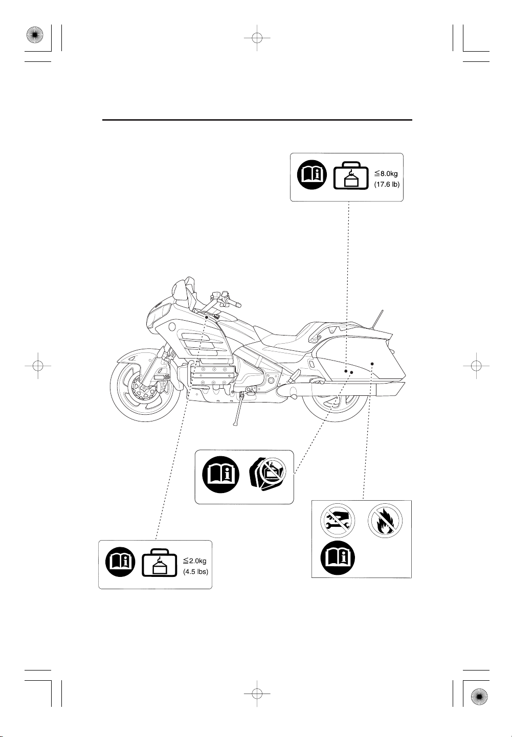
IMAGE LABELS
Except KO, SI type
The following pages describe the label meanings. Some labels warn you of
potential hazards that could cause serious injury. Others provide important
safety information. Read this information carefully and don’t remove the labels.
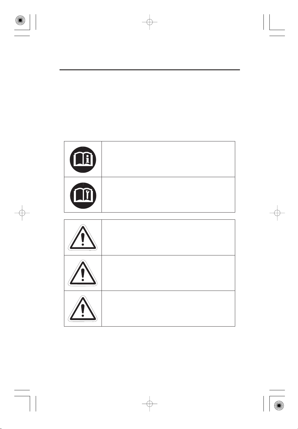
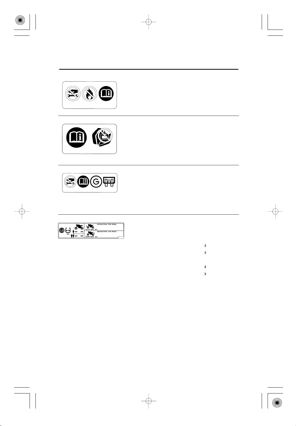
There is a specific symbol on each label. The meanings of each symbol and
label are as f ollows.
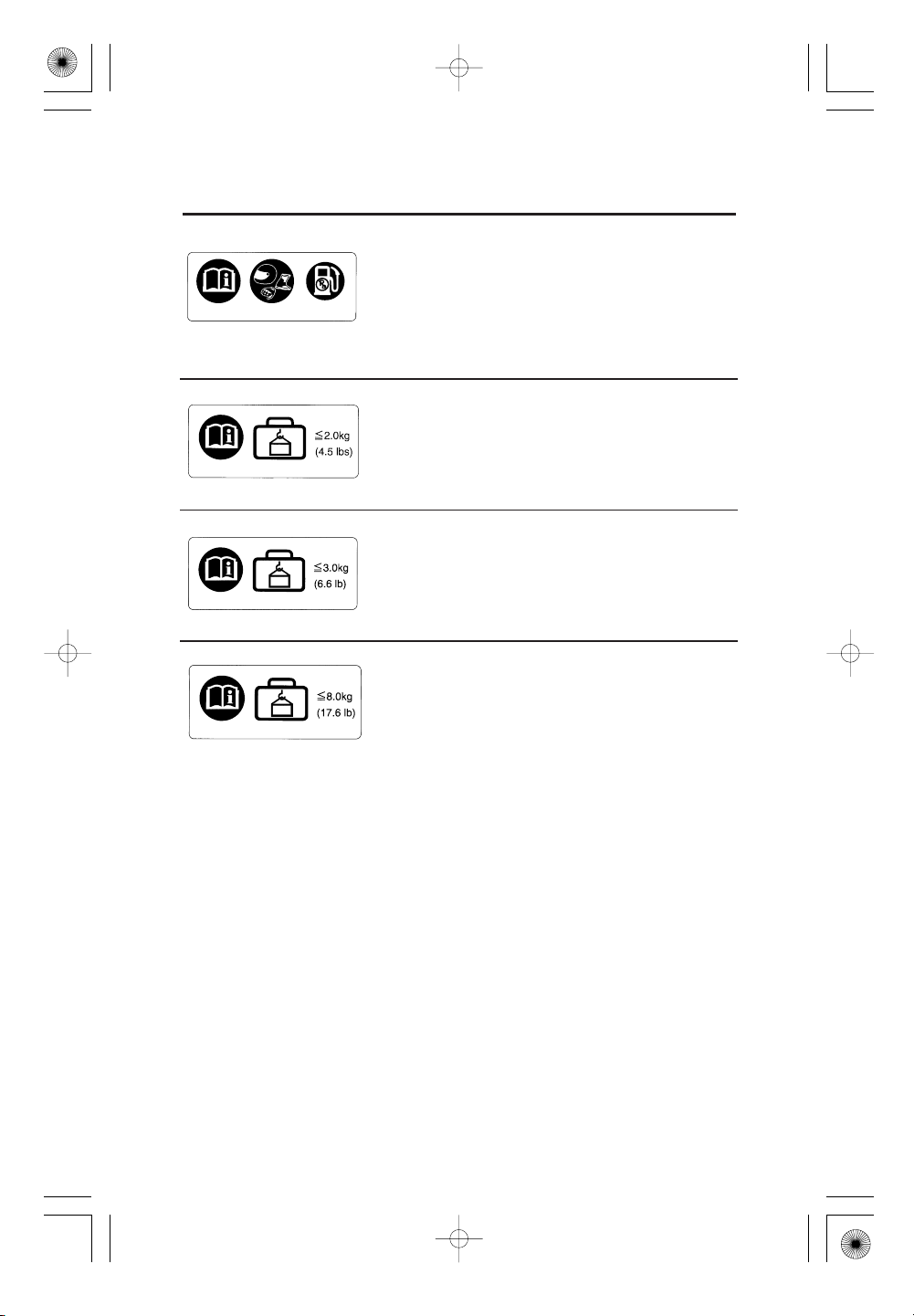
Read instructions contained in Owner’s Manual
carefully.
Read instructions contained in Shop Manual carefully.
In the interest of safety, take the motorcycle to be
serviced only by your dealer.
DANGER (with RED background)
You WILL be KILLED or SERIOUSLY HURT if you
don’t follow instructions.
WARNING (with ORANGE background)
You CAN be KILLED or SERIOUSLY HURT if you
don’t follow instructions.
CAUTION (with YELLOW background)
You CAN be HURT if you don’t follow instructions.
8
Page 19
12/12/06 16:13:25 32MJG600_019
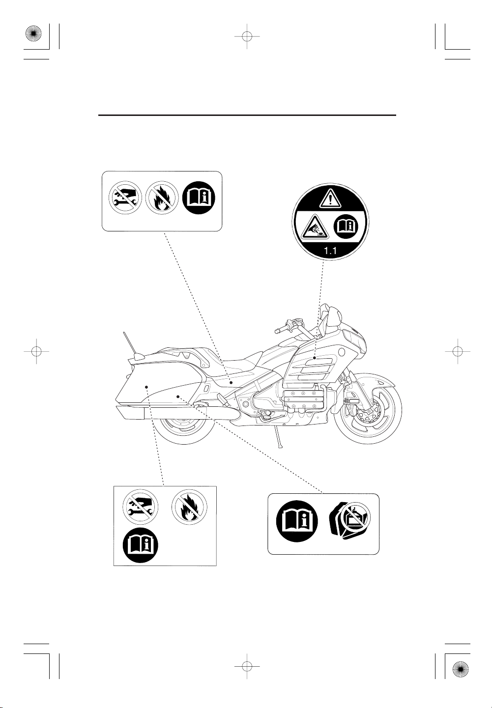
RADIATOR CAP LABEL
DANGER
NEVER OPEN WHEN HOT.
Hot coolant will scald you.
Relief pressure valve begins to open at
2
1.1 kgf/cm
.
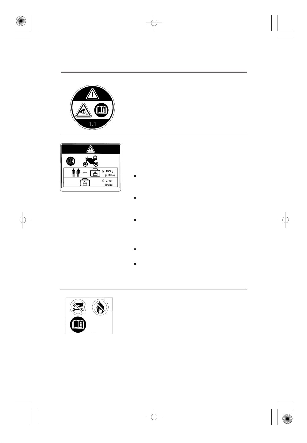
ACCESSORIES AND LOADING WARNING
LABEL
WARNING
ACCESSORIES AND LOADING
The safety stability and handling of this
motorcyclemaybeaffectedbytheaddition
of accessories and luggage.
Read carefully the instructions contained in
user’s manual and installation guide before
installing any accessory.
The total weight of accessories and luggage
added to rider’s and passenger’s weight
should not exceed , which
190 kg (419 lb)
is the maximum weight capacity.
The luggage weight must not exceed
27 kg (60 lb)
under any circumstances.
The fitting of large fork-mounted or large
handlebar-mounted fairing is not
recommended.
SADDLEBAG DAMPER LABEL
CONTENTS UNDER PRESSURE
Do not puncture, take apart or apply heat.
Do not apply side force.
9
Page 20
12/12/06 16:13:38 32MJG600_020
MOTORCYCLE SAFETY
REAR CUSHION LABEL
GAS FILLED
Do not open.
Do not heat.
SADDLEBAG LABEL
NOTICE
Heavycargoplacedontheopenlidcan
damage the saddlebag and lid.
ACG CABLE LABEL
NOTICE
Before removing alternator cable, disconnect
battery negative cable to prevent damage to
the main fuse.
10
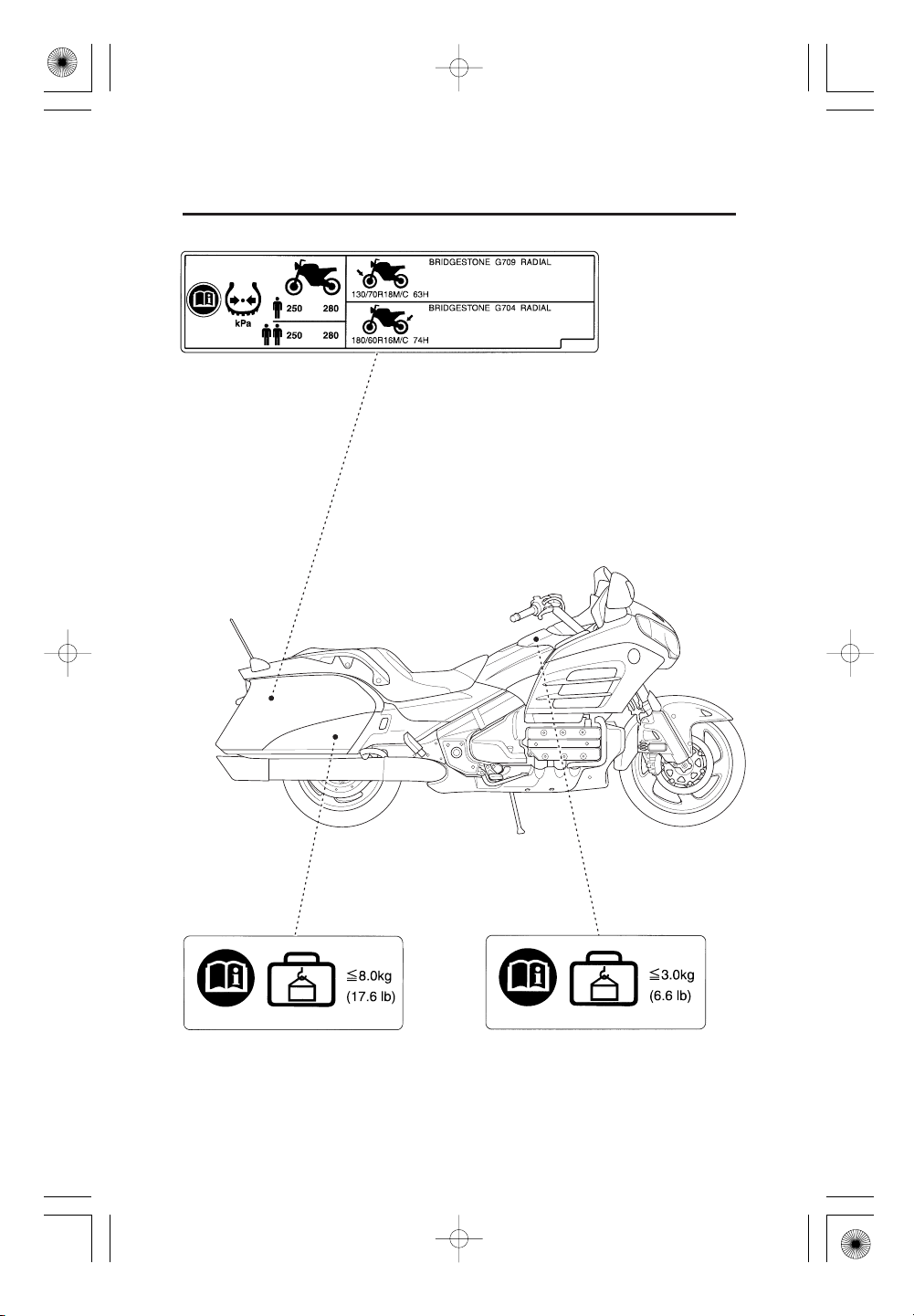
TYRE INFORMATION LABEL
Cold tyre pressure:
[Driver only]
Front
Rear
[Driver and passenger]
Front
Rear
Tyre size:
Front
Rear
Tyre brand:
Front
Rear
250 kPa (2.50 kgf/cm
280 kPa (2.80 kgf/cm
250 kPa (2.50 kgf/cm
280 kPa (2.80 kgf/cm
130/70R18M/C 63H
180/60R16M/C 74H
BRIDGESTONE
G709 RADIAL
G704 RADIAL
, 36 psi)
, 41 psi)
, 36 psi)
, 41 psi)
Page 21
12/12/06 16:13:49 32MJG600_021
SAFETY REMINDER LABEL
For your protection, always wear your helmet
while riding.
FUEL LABEL
UNLEADED PETROL ONLY
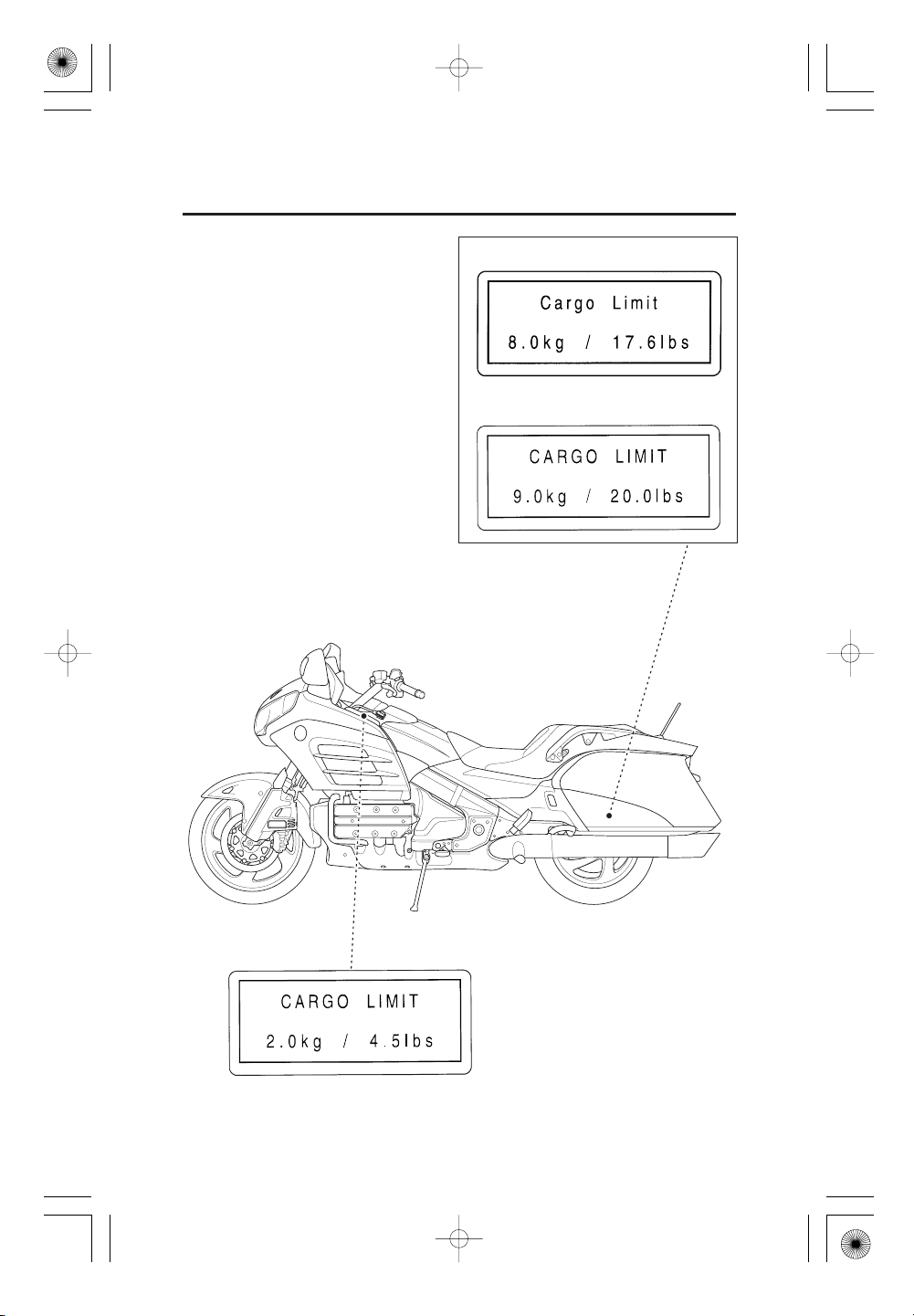
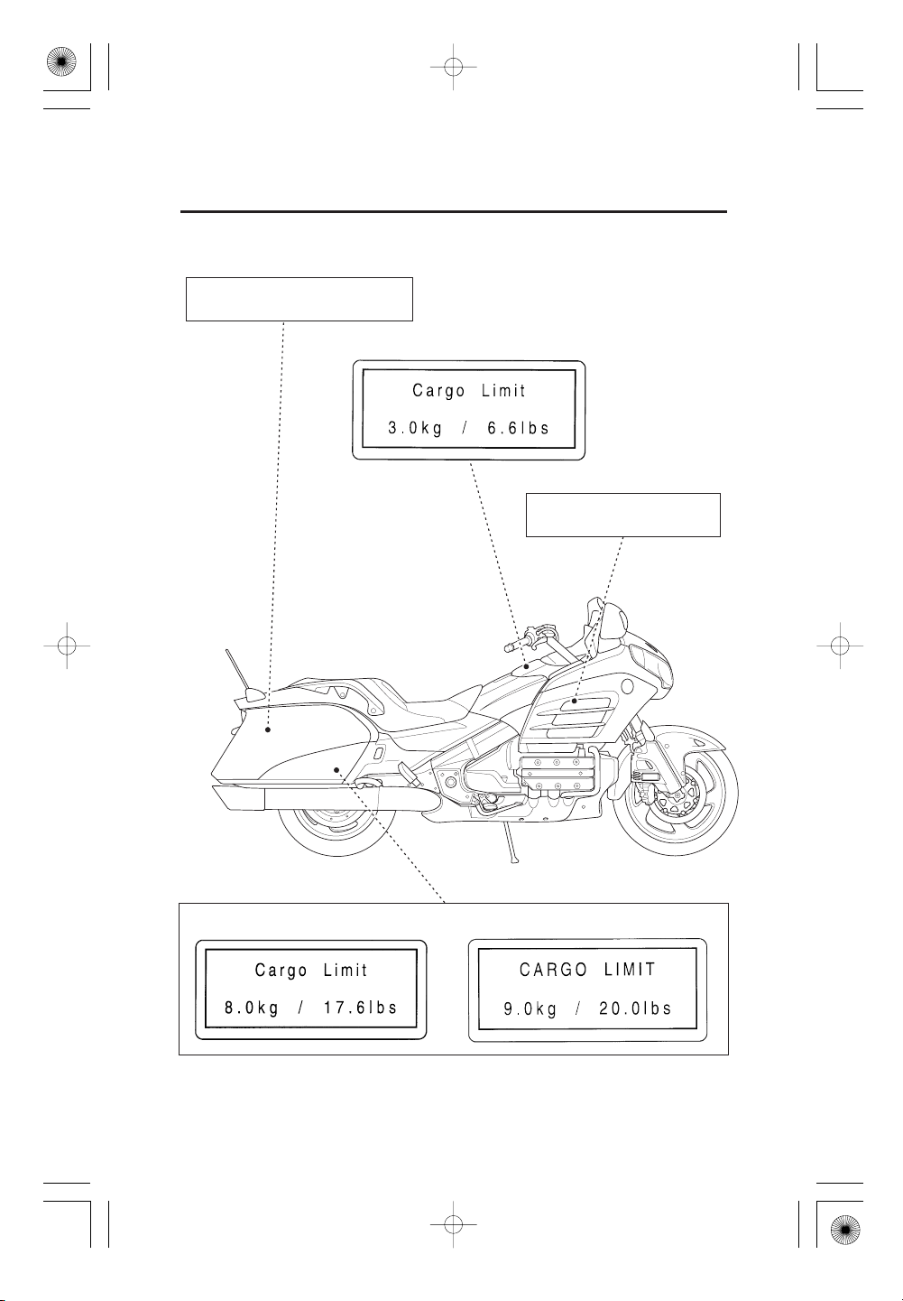
CARGO LIMIT LABEL
Do not exceed .
CARGO LIMIT LABEL
Do not exceed .
2.0 kg (4.5 lb)
3.0 kg (6.6 lb)
CARGO LIMIT LABEL
Do not exceed .
8.0 kg (17.6 lb)
11
Page 22
12/12/06 16:13:55 32MJG600_022
MOTORCYCLE SAFETY
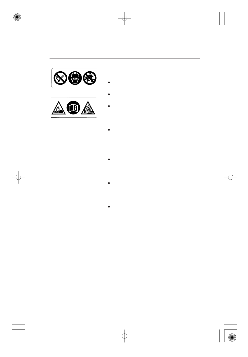
BATTERY LABEL
DANGER
Keep flames and sparks away from the
battery.
The battery produces explosive gas that can
cause an explosion.
Wear eye protection and rubber gloves
when handling the battery to avoid risk of
burns or loss of eyesight if exposed to
battery electrolyte.
Do not allow children to handle the battery,
under any circumstance. Ensure that
anyone handling the battery has a proper
understanding of the hazards and correct
handling procedures involved.
Handle battery electrolyte with extreme
care, as it contains dilute sulfuric acid.
Exposure to eyes or skin can cause burns or
loss of eyesight.
Read this manual carefully, and understand
it before handling the battery. Failure to do
so can cause personal injury and damage to
the vehicle.
Do not use the battery if the level of
electrolyte is at or below the recommended
level. Using the battery with low electrolyte
can cause it to explode, causing serious
injury.
12
Page 23
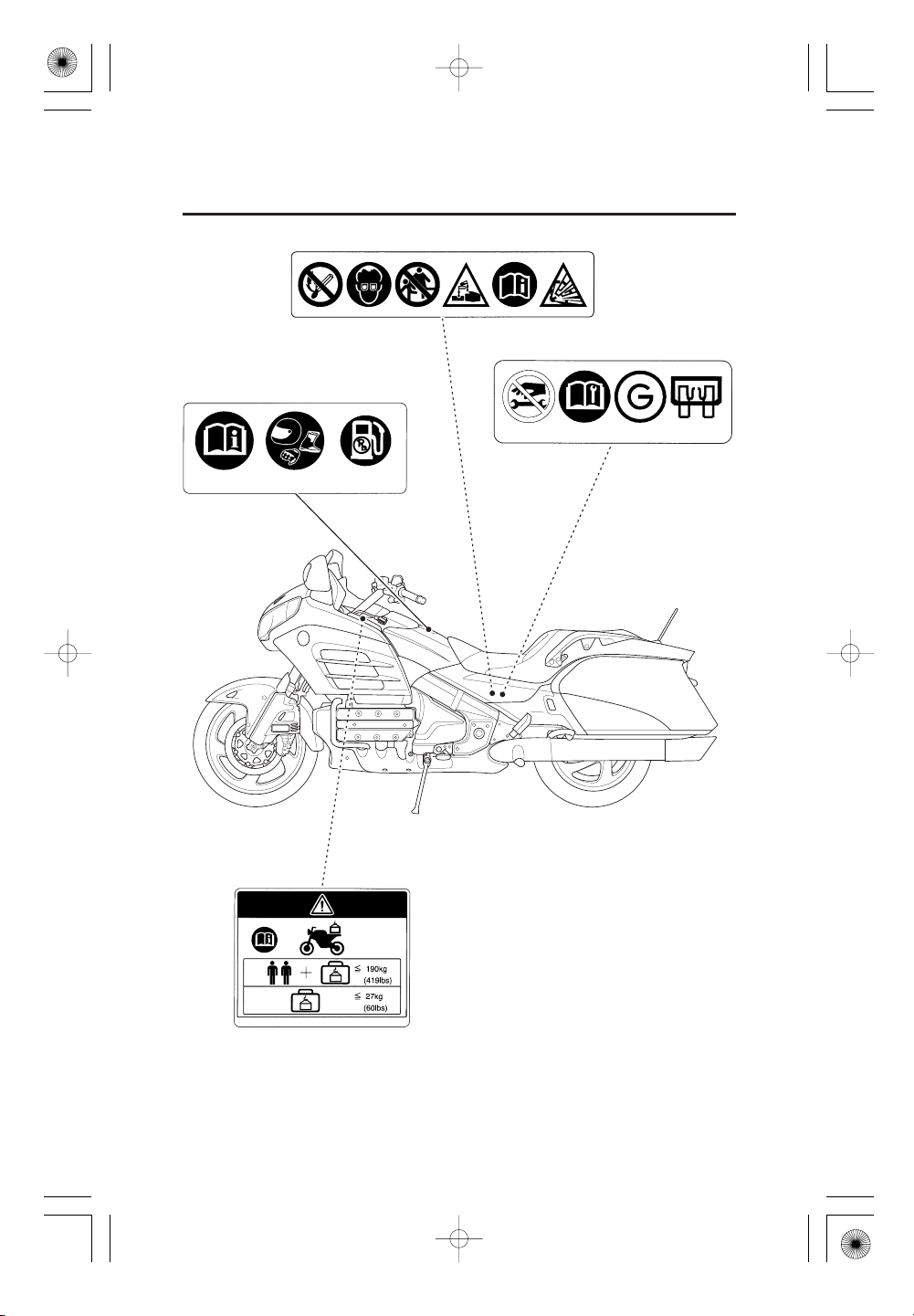
12/12/06 16:14:04 32MJG600_023
FUEL/SAFETY REMINDER
LABEL
BATTERY LABEL
ACG CABLE LABEL
ACCESSORIES AND LOADING
WARNING LABEL
13
Page 24
12/12/06 16:14:13 32MJG600_024
MOTORCYCLE SAFETY
CARGO LIMIT LABEL
CARGO LIMIT LABEL
14
SADDLEBAG LABEL
SADDLEBAG DAMPER
LABEL
Page 25
12/12/06 16:14:21 32MJG600_025
TYRE INFORMATION LABEL
CARGO LIMIT LABEL CARGO LIMIT LABEL
15
Page 26
12/12/06 16:14:30 32MJG600_026
MOTORCYCLE SAFETY
REAR CUSHION LABEL
RADIATOR CAP LABEL
SADDLEBAG DAMPER LABEL
16
SADDLEBAG LABEL
Page 27

12/12/06 16:14:34 32MJG600_027
SAFETY LABELS
KO,SI type
The following pages show the locations of safety labels on your motorcycle.
Some labels warn you of potential hazards that could cause serious injury.
Others provide important safety information. Read these labels carefully and
don’t remove them.
If a label comes off or becomes hard to read, contact your dealer for a
replacement.
SAFETY REMINDER LABEL
17
Page 28
12/12/06 16:14:40 32MJG600_028
MOTORCYCLE SAFETY
For SI type
For KO type
18
Page 29
12/12/06 16:14:45 32MJG600_029
TYRE INFORMATION LABEL
RADIATOR CAP LABEL
For SI type
For KO type
19
Page 30
12/12/06 16:14:49 32MJG600_030
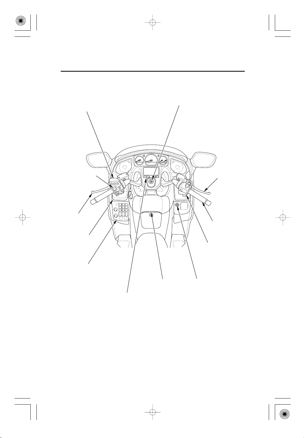
PARTS LOCATION
Audio system controls
(E,F,EDtype)
Left handlebar
controls
Clutch lever
Fairing pocket
Audio system controls
Ignition switch
Front brake lever
Throttle grip
Right handlebar
controls
20
Shelter case
Multi information display controls
Shelter case lock
Page 31

12/12/06 16:14:52 32MJG600_031
Radio antenna
Saddlebag
Rear brake pedal
21
Page 32

12/12/06 16:14:56 32MJG600_032
PARTS LOCATION
Front headset terminal
Shift lever
Helmet holder
Saddlebag
22
Page 33

12/12/06 16:15:01 32MJG600_033
INSTR UMENTS AND INDICATORS
The indicators and warning lights are incorporated in the instrument panel.
Their functions are described on the following pages.
Tachometer red zone Right turn signal indicator
Left turn signal indicator
Tachometer
Immobiliser system
(HISS) indicator
PGM-FI malfunction
indicator lamp (MIL)
Speedometer
Coolant
temperature
gauge
Anti-lock Brake System
(ABS) indicator
Neutral indicator
Overdrive indicator
Low oil pressure indicator
Low f uel indicator
Fuel gauge
High beam indicator
23
Page 34

12/12/06 16:15:12 32MJG600_034
PARTS LOCATION
Speedometer
Shows riding speed.
This shows your speed in kilometers per hour (km/h) and/or miles per hour
(mph) depending on the type.
Tachometer
Shows engine speed in revolutions per minute.
Tachometer red zone
Never allow the tachometer needle to enter the red zone, even after the engine
has been broken in.
Running the engine beyond recommended maximum engine speed (the
beginning of the tachometer red zone) can damage the engine.
Turn signal indicators (green)
Flashes when a turn signal operates.
Neutral indicator (green)
Lights when the transmission is in neutral.
24
Page 35

12/12/06 16:15:20 32MJG600_035
Overdrive indicator (orange)
Lights when the transmission is in overdrive (5th gear).
Low oil pressure indicator (red)
Lights when the engine oil pressure is below normal operating range. Should
light when ignition switch is ON and engine is not running. Should go out when
the engine starts, except f or occasional flickering at or near idling speed when
engine is warm.
Running the engine with insufficient oil pressure may cause serious engine
damage.
PGM-FI malfunction indicator lamp (MIL)
(orange)
Lights when there is any abnormality in the PGM-FI (Programmed Fuel
Injection) system. Should also light for a few seconds and then go off when the
ignition switch is turned ON and engine stop switch is at (RUN). If the
indicator comes on at any other time, reduce speed and take the motorcycle to
your dealer as soon as possible.
Anti-lock Brake System
(ABS) indicator
(orange)
This light normally comes on when the ignition is turned ON, and goes off
after you ride the motorcycle at speed above 10 km/h (6 mph). If there is a
problem with the Anti-lock Brake System, this light flashes and remains on
(page ).120
25
Page 36

12/12/06 16:15:31 32MJG600_036
PARTS LOCATION
High beam indicator (blue)
Lights when the headlight is on high beam.
Immobilizer system
(HISS) indicator
(red)
This indicator lights for a few seconds when the ignition switch is turned ON
and the engine stop switch is at (RUN). It will then go of f if the properlycoded key has been inserted. If an improperly-coded key has been inserted, the
indicator will remain on and the engine will not start (page ).
Low f uel indicator (orange)
55
Lights when there is only few fuel left in the fuel tank. Amount of fuel left in
the tank with the vehicle set upright is approximately;
4.4 (1.16 US gal , 0.97 Imp gal)
Fuel gauge
Shows approximate fuel supply available (page ).
Coolant temperature gauge
Shows engine coolant temperature (page ).27
27
26
Page 37

12/12/06 16:15:37 32MJG600_037
Fuel Gauge
When the gauge needle enters the red band, fuel will be low and you should
refill the tank as soon as possible.
The amount of fuel left in the tank when the needle enters the red band and
with the vehicle set upright is approximately:
3.0 (0.79 US gal , 0.66 Imp gal)
Needle
Red band
Coolant Temperature Gauge
When the needle begins to move above the C (Cold) mark, the engine is warm
enough for the motorcycle to be ridden. The normal operating temperature
range is within the section between the H and C marks. If the needle reaches
the H (Hot) mark, stop the engine and check the reserve tank coolant level.
Read pages and do not ride the motorcycle until the problem has been
corrected.
42 43
−
Exceeding maximum running temperature may cause serious engine damage.
Needle
27
Page 38

12/12/06 16:15:41 32MJG600_038
PARTS LOCATION
MULT I INFORMATION DISPLAY
Your motorcycle is equipped with a Multi Information Display that presents
various displays. This section explains display functions and operations.
SETUP button DIM button
28
INFO button TRIP button
Page 39

12/12/06 16:15:46 32MJG600_039
Opening/Ending Ceremony
When the ignition switch is turned ON or ACC, the display presents an
‘‘opening ceremony’’.
When the ignition switch is turned OFF, the display presents an ‘‘ending
ceremony’’.
29
Page 40

12/12/06 16:15:54 32MJG600_040
PARTS LOCATION
The opening/ending ceremony can be turned off.
1.
Push the SETUP button to show the CLOCK ADJUST display.
2.
Push the DIM button to show the OPENING/ENDING CEREMONY display.
3.
Push the TRIP or INFO button to switch ON/OFF.
4.
Push the SETUP button to fix the setting.
When approximately 5 seconds pass without operating a button on the
OPENING/ENDING CEREMONY display, the display automatically returns
to the previous display.
Ceremony Display ON
Ceremony Display OFF
30
Page 41

12/12/06 16:16:03 32MJG600_041
Odometer/Tripmeter
ODO (Odometer)
TRIP (Tripmeter)
shows the total miles (For E type) or kilometer
(Except E type) ridden.
shows the number of miles (For E type) or
kilometer (Except E type) ridden.
Odometer
TripmeterTRIP button
The tripmeter will show mileage in two sub modes, ‘‘T RIP A’’ and ‘‘TRIP B.’’
Push the TRIP button to select the ‘‘TRIP A’’ or ‘‘T RIP B’’ mode.
Toresetthetripmeter,pushandholdtheTRIPbuttonwiththedisplayinthe
‘‘TRIP A’’ or ‘‘TRIP B’’ mode.
31
Page 42

12/12/06 16:16:12 32MJG600_042
PARTS LOCATION
Display Illumination Adjustment
To adjust the brightness of the display:
Push the DIM button once. ‘‘DIMMER’’ will display.
To brighten the display
To darken the display
(The brighter and darker ranges each have six steps.)
To set the selected step push the SETUP button.
push the TRIP button ( ).
push the INFO button ( ).
INFO button DIM button
TRIP buttonSETUP button
+
−
32
Page 43

12/12/06 16:16:22 32MJG600_043
Digital Clock
The display shows the hour and minute.
To adjust the time:
1.
Turn the ignition switch to ON or ACC.
2.
Push the SETUP button once. ‘‘CLOCK ADJUST’’ will display.
3.
To set the hour, press and release the INFO button until the desired hour
appears.
Quick setting push and hold the INFO button until the desired hour
4.
To set the minute, press and release the TRIP button until the desired
minute appears.
Quick setting push and hold the TRIP button until the desired
5.
Once the time is selected, push the SETUP button to enter the time.
When approximately 5 seconds pass without operating a button on the CLOCK
ADJUST display, the display automatically returns to the previous display.
appears.
minute appears.
Be sure to push the SETUP button to enter your adjusted time in the system.
SETUP button
TRIP buttonINFO button
33
Page 44

12/12/06 16:16:29 32MJG600_044
PARTS LOCATION
Air Temperature Meter
Push the INFO button once to display the air temperature.
After 5 seconds, the previous display returns.
Temperature Display
−
Below 11°C
Between: 10°C 50°C
Above 50°C
−―
−−
‘‘ ’’ is displayed.
Actual air temperature is indicated.
The display will remain ‘‘50°C’’.
The temperature sensor is located in the upper fairing. The temperature
reading can be af fected by heat ref lecting from the road surface, engine heat,
and the exhaust from surrounding traffic. This can cause an error in the
temperature reading when your speed is under 30 km/h (19 mph).
INFO button
34
Page 45

12/12/06 16:16:34 32MJG600_045
Saddlebags Open Indicator
This indicator turns on when the ignition switch is ON and your motorcycle’s
saddlebags are open.
If saddlebag(s) are not fully closed, the display will blink OPEN and indicate
the open saddlebag(s).
Open indicator
Saddlebag Open
35
Page 46

12/12/11 11:10:48 32MJG600_046
MAJOR COMPONENTS
(Information you need to operate this motorcycle)
REAR SUSPENSION
Spring Preload:
The spring preload adjuster is located behind the right side cover.
The spring preload adjuster knob has 35 spring preload positions (clicks) or
more for diff erent load or riding conditions.
To adjust the spring preload, turn the adjuster knob.
To reduce (LOW) :
Turn the adjuster counterclockwise toward LOW for a light load and smooth
road condition.
To increase (HIGH) :
Turn the adjuster clockwise toward HIGH for a firmer ride and rough road
condition.
To adjust to the standard position:
1.
Remove the right side cover (page ).
2.
Turn the spring preload adjuster knob counterclockwise until it will no
longer turn (lightly seats).
This is the full LOW setting.
Turn the adjuster clockwise for 1 click. This is the standard position.
Adjuster knob
The rear shock absorber assembly includes a damper unit that contains high
pressure nitrogen gas. Do not attempt to disassemble or service the damper; it
cannot be rebuilt and must be replaced when worn out. Disposal should only be
done by your dealer. The instructions found in this owner’s manual are limited
to adjustment of the shock assembly only.
138
36
Page 47

12/12/06 16:16:47 32MJG600_047
BRAKES
Both the front and rear brakes are the hydraulic disc types.
As the brake pads wear, the brake f luid level drops.
There are no adjustments to perform, but fluid level and pad wear must be
inspected periodically. The system must be inspected f requently to ensure
there are no fluid leaks. If the control lever or pedal free travel becomes
excessiveandthebrakepadsarenotwornbeyondtherecommendedlimit
162
(page ), there is probably air in the brake system and it must be bled. See
your dealer for this service.
Front Brake Fluid Level:
Withthemotorcycleinanuprightposition,checkthefluidlevel.Itshouldbe
above the LOWER level mark. If the level is at or below the LOWER level
mark, check the brake pads for wear (page ).
Worn pads should be replaced. If the pads are not worn, have your brake
system inspected for leaks.
162
The recommended brake f luid is Honda DOT 4 brake fluid from a sealed
container, or an equivalent.
LOWER level mark
37
Page 48

12/12/06 16:16:52 32MJG600_048
MAJOR COMPONENTS
(Information you need to operate this motorcycle)
Thedistancebetweenthetipofthebrakeleverandthegripcanbeadjusted.
1.
Turn the adjuster dial while pushing the brake lever forward.
2.
Align the index mark on the brake lever with the numbers on the adjuster
dial.
Apply the brake, release it, then spin the wheel and check that it rotates
3.
freely. Repeat this procedure several times.
Adjuster dial
38
Brake lever
Index mark
Page 49

12/12/06 16:16:57 32MJG600_049
Rear Brake Fluid Level:
Withthemotorcycleinanuprightposition,checkthefluidlevel.Itshouldbe
between the UPPER and LOWER level marks. If the level is at or below the
LOWER level mark, check the brake pads for wear (page ).
Worn pads should be replaced. If the pads are not worn, have your brake
system inspected for leaks.
The recommended brake f luid is Honda DOT 4 brake fluid from a sealed
container, or an equivalent.
162
UPPER level mark
LOWER level mark
Other Checks:
Make sure there are no fluid leaks. Check f or deterioration or cracks in the
hoses and fittings.
39
Page 50

12/12/06 16:17:02 32MJG600_050
MAJOR COMPONENTS
(Information you need to operate this motorcycle)
CLUTCH
This motorcycle has a hydraulically actuated clutch. T here are no adjustments
to perform, but the clutch system must be inspected periodically for fluid level
and leakage.
If the motorcycle creeps or stalls when shifted into gear, or if the clutch slips,
causing acceleration to lag behind engine speed, there is probably air in the
clutch system and it must be bled out. See your dealer for this service.
Fluid Level:
Check that the fluid level is above the LOWER level mark. If the fluid level is
near the LOWER level mark, it indicates fluid leakage. See your dealer for
repair.
40
LOWER level mark
Page 51

12/12/06 16:17:08 32MJG600_051
Thedistancebetweenthetipoftheclutchleverandthegripmaybeadjusted.
Adjuster dial
Clutch lever
Index mark
1.
Turn the adjuster dial while pushing the clutch lever forward.
2.
Align the index mark on the clutch lever with the numbers on the adjuster
dial.
3.
Start the engine, pull in the clutch lever and shif t into gear. Make sure the
engine does not stall and the motorcycle does not creep. Gradually release
the clutch lever and open the throttle. The motorcycle should begin to move
smoothly and accelerate gradually.
Other Checks:
Make sure there are no fluid leaks. Check f or deterioration or cracks in the
hoses and fittings.
41
Page 52

12/12/06 16:17:13 32MJG600_052
MAJOR COMPONENTS
(Information you need to operate this motorcycle)
COOLANT
Coolant Recommendation
The owner must properly maintain the coolant to prevent freezing, overheating,
and corrosion. Use only high quality ethylene glycol antifreeze containing
corrosion protection inhibitors specifically recommended for use in aluminum
engines. (SEE ANTIFREEZE CONTAINER LABEL).
Use only low-mineral drinking water or distilled water as a part of the
antifreeze solution. Water that is high in mineral content or salt may be
harmful to the aluminum engine.
Using coolant with silicate inhibitors may cause premature wear of water pump
seals or blockage of radiator passages.
Using tap water may cause engine damage.
The factory provides a 50/50 solution of antifreeze and distilled water in this
motorcycle. This coolant solution is recommended for most operating
temperatures and provides good corrosion protection. A higher concentration
of antifreeze decreases the cooling system performance and is recommended
only when additional protection against f reezing is needed. A concentration of
less than 40/60 (40% antifreeze) will not provide proper corrosion protection.
During freezing temperatures, check the cooling system frequently and add
higher concentrations of antifreeze (up to a maximum of 60% antifreeze) if
required.
42
Page 53

12/12/06 16:17:18 32MJG600_053
Inspection
The reserve tank is behind the lef t engine side cover.
Remove the left engine side cover (page ).
Check the coolant level in the reserve tank while the engine is at normal
operating temperature with the motorcycle in an upright position. Add coolant
to the reserve tank as required to bring coolant level to the UPPER level mark.
Alwaysaddcoolanttothereservetank.Donotattempttoaddcoolantby
removing the radiator cap.
If the reserve tank is empty, or if coolant loss is excessive, check f or leaks and
see your dealer for repair.
Reserve tank cap/dipstick
139
Upper level
Lower level
43
Page 54

12/12/06 16:17:26 32MJG600_054
MAJOR COMPONENTS
(Information you need to operate this motorcycle)
FUEL
Fuel Tank
The f uel tank capacity including the reserve supply is:
25 (6.6 US gal , 5.5 Imp gal)
To open the fuel fill cap, insert the ignition key and turn it clockwise to open
the fuel filler lid. Turn the fuel fill cap counterclockwise to remove it.
Do not overf ill the tank. There should be no f uel in the filler neck.
After refueling, be sure to tighten the fuel fill cap f irmly by turning it clockwise
until it clicks.
Close the fuel fill lid.
Remove the key from the fuel fill lid.
Petrol is highly flammable and
explosive. You can be burned or
seriously injured when handling fuel.
Ignition key
Fuel fill lid
44
Stop the engine and keep heat,
sparks, and flame away.
Refuel only outdoors.
Wipe up spills immediately.
Fuel fill cap
Filler neck
Page 55

12/12/06 16:17:30 32MJG600_055
Use unleaded petrol with a research octane number of 91 or higher.
The use of leaded petrol will cause premature damage to the catalytic
converter.
Occasionally you may experience light spark knock while operating under
heavy loads. This is no cause for concern, it simply means your engine is
operating efficiently.
If ‘‘spark knock’’ or ‘‘pinking’’ occurs at a steady engine speed under normal
load, change brands of petrol. If spark knock or pinking persists, consult your
dealer. Failure to do so is considered misuse, and damage caused by misuse is
not covered by Honda’s Limited Warranty.
45
Page 56

12/12/06 16:17:34 32MJG600_056
MAJOR COMPONENTS
(Information you need to operate this motorcycle)
Petrol Containing Alcohol
If you decide to use a petrol containing alcohol (gasohol), be sure it’s octane
rating is at least as high as that recommended by Honda. There are two types
of ‘‘gasohol’’: one containing ethanol, and the other containing methanol. Do
not use petrol that contains more than 10 % ethanol. Do not use petrol
containing methanol (methyl or wood alcohol) that does not also contain
cosolvents and corrosion inhibitors for methanol. Never use petrol containing
more than 5 % methanol, even if it has cosolvents and corrosion inhibitors.
The use of petrol containing more than 10 % ethanol (or more than 5 %
methanol) may:
Damage the painting of the fuel tank.
Damage the rubber tubes of the f uel line.
Cause corrosion of the fuel tank.
Cause poor drivability.
Before buying fuel from an unfamiliar station, try to find out if the fuel contains
alcohol. If it does, confirm the type and percentage of alcohol used. If you
notice any undesirable operating symptoms while using a petrol that contains
alcohol, or one that you think contains alcohol, switch to a petrol that you know
does not contain alcohol.
46
Page 57

12/12/06 16:17:42 32MJG600_057
ENGINE OIL
Engine Oil Level Check
Check engine oil level each day before operating the motorcycle.
To Check the Oil Level:
1.
Remove the right engine side cover (page ).
2.
Start the engine and let it idle for 3 5 minutes.
3.
Stop the engine and hold the motorcycle in an upright position on a firm,
level ground.
4.
After 2 3 minutes, remove the oil fill cap/dipstick, wipe it clean, and
−
reinsert the oil fill cap/dipstick without screwing it in. Remove the oil fill
cap/dipstick. The oil level should be between the upper and lower level
marks on the oil f ill cap/dipstick.
5.
If required, add the specif ied oil up to the upper level mark. Do not overf ill.
Reinstall the oil fill cap/dipstick, and the right engine side cover.
6.
Running the engine with insufficient oil can cause serious engine damage.
139
−
Oil fill cap/dipstick
Upper level mark
Lower level mark
47
Page 58

12/12/06 16:17:47 32MJG600_058
MAJOR COMPONENTS
(Information you need to operate this motorcycle)
TUBELESS TYRES
To safely operate your motorcycle, your tyres must be the proper type and size,
in good condition with adequate tread, and correctly inflated for the load you
are carrying. The following pages give more detailed information on how and
when to check your air pressure, how to inspect your tyres for damage, and
what to do when your tyres need to be repaired or replaced.
Using tyres that are excessively
worn or improperly inflated can
cause a crash in which you can be
seriously hurt or killed.
Follow all instructions in this owner’s
manual regarding tyre inflation and
maintenance.
Air Pressure
Keeping your tyres properly inf lated provides the best combination of handling,
tread life and riding comfort. Generally, underinflated tyres wear unevenly,
adversely affect handling, and are more likely to fail from being overheated.
Overinflated tyres make your motorcycle ride harshly, are more prone to
damage from road hazards, and wear unevenly.
We recommend that you visually check your tyres before every ride and use a
gauge to measure air pressure at least once a month or any time you think the
tyres might be low.
Tubeless tyres have some self -sealing ability if they are punctured. However,
because leakage is often very slow, you should look closely for punctures
whenever a tyre is not fully inflated.
48
Page 59

12/12/06 16:17:52 32MJG600_059
Always check air pressure when your tyres are ‘‘cold’’ when the motorcycle
has been parked for at least three hours. If you check air pressure when your
tyres are ‘‘warm’’ when the motorcycle has been ridden for even a f ew
kilometers the readings will be higher than if the tyres were ‘‘cold’’. This is
normal, so do not let air out of the tyres to match the recommended cold air
pressures given below. If you do, the tyres will be underinflated.
The recommended ‘‘cold’’ tyre pressures are:
Front
Rear
Inspection
Whenever you check the tyre pressures, you should also examine the tyre
treads and sidewalls for wear, damage, and foreign objects:
Look for:
Bumps or bulges in the side of the tyre or the tread. Replace the tyre if you
find any bumps or bulges.
Cuts, splits or cracks in the tyre. Replace the tyre if you can see fabric or
cord.
Excessive tread wear.
Also, if you hit a pothole or hard object, pull to the side of the road as soon as
you can safely and caref ully inspect the tyres f or damage.
−
−
250 kPa (2.50 kgf/cm , 36 psi)
280 kPa (2.80 kgf/cm
−
, 41 psi)
49
Page 60

12/12/06 16:18:00 32MJG600_060
MAJOR COMPONENTS
(Information you need to operate this motorcycle)
Tread Wear
Replace tyres before tread depth at the centre of the tyre reaches the following
limit:
Front
Rear
For Germany
<>
German law prohibits use of tyres whose tread depth is less than 1.6 mm.
Wear indicator
Minimum tread depth
1.5 mm (0.06 in)
2.0 mm (0.08 in)
Wear indicator location mark
Tyre Repair
If a tyre is punctured or damaged, you should replace it, not repair it. As
discussed below, a tyre that is repaired, either temporarily or permanently, will
have lower speed and performance limits than a new tyre.
A temporary repair, such as an external tubeless tyre plug, may not be safe for
normal speeds and riding conditions. If a temporary or emergency repair is
made to a tyre, you should ride slowly and cautiously to a dealer and have the
tyre replaced. If possible, you should not carry a passenger or cargo until a new
tyre is installed.
Even if a tyre is professionally repaired with a permanent internal patch plug, it
will not be as good as a new tyre. You should not exceed 80 km/h (50 mph) for
the first 24 hours, or 130 km/h (80 mph) at any time thereaf ter. In addition,
you may not be able to safely carry as much weight as with a new tyre.
Therefore, we strongly recommend that you replace a damaged tyre. If you
choose to have a tyre repaired, be sure the wheel is balanced before you ride.
50
Page 61

12/12/06 16:18:06 32MJG600_061
Tyre Replacement
The tyres that came on your motorcycle were designed to match the
performance capabilities of your motorcycle and provide the best combination
of handling, braking, durability and comfort.
Installing improper tyres on your
motorcycle can affect handling and
stability. This can cause a crash in
which you can be seriously hurt or
killed.
Always use the size and type of
tyres recommended in this owner’s
manual.
The recommended tyres for your motorcycle are:
Front
Rear
Type
Whenever you replace a tyre, use one that is equivalent to the original and be
sure the wheel is balanced af ter the new tyre is installed.
130/70R18M/C 63H
BRIDGESTONE
180/60R16M/C 74H
BRIDGESTONE
radial, tubeless
G709 RADIAL
G704 RADIAL
51
Page 62

12/12/06 16:18:12 32MJG600_062
MAJOR COMPONENTS
(Information you need to operate this motorcycle)
Important Safety Reminders
Do not install a tube inside a tubeless tyre on this motorcycle. Excessive heat
build-up can cause the tube to burst.
Use only tubeless tyres on this motorcycle. The rims are designed for
tubeless tyres, and during hard acceleration or braking, a tube-type tyre
could slip on the rim and cause the tyre to rapidly deflate.
Do not install a bias-ply tyre on this motorcycle. Mixing bias-ply and radial
tyres can adversely affect handling and stability.
Do not install car tyres on this motorcycle. During installation the tyre may
separate from the rim with enough force to cause serious injury or death.
When replacing tyres, use only the recommended tyres as shown above and
on the tyre inf ormation label. Use of other tyres on the model equipped with
ABS may impair proper ABS function.
The ABS computer works by comparing wheel speed.
Non-recommended tyres can affect wheel speed and may confuse the ABS
computer.
52
Page 63

12/12/06 16:18:18 32MJG600_063
ESSENTIAL INDIVIDUAL COMPONENTS
IGNITION SWITCH
The ignition switch is on the handlebar cover.
Key Position Function Key Removal
ACC
ON
OFF
LOCK
(steering lock)
If your motorcycle is stopped with the ignition switch ON and the engine stop
switch (OFF), the headlight and taillight will still be on, resulting in battery
discharge.
Only the accessory circuits
function.
Electrical circuits on.
No electrical circuits function.
No electrical circuits function.
Locks the steering head.
cannot be removed
cannot be removed
can be removed
can be removed
ON
OFF
ACC
LOCK
53
Page 64

12/12/06 16:18:27 32MJG600_064
ESSENTIAL INDIVIDUAL COMPONENTS
KEYS
This motorcycle has two keys and a key number plate.
Key number plate
You will need the key number if you ever have to replace a key. Store the plate
in a safe place.
To reproduce keys, bring all keys, key number plate and motorcycle to your
dealer.
Up to four keys can be registered with the immobilizer system (HISS),
including the ones in hand.
If all keys are lost, the PGM-FI unit/ignition control module must be replaced.
To avoid this possibility we recommend that if only one key is left, you
immediately have it reproduced to ensure that a back-up is available.
These keys contain electronic circuits that are activated by the immobilizer
system (HISS). They will not work to start the engine if the circuits are
damaged.
Donotdropthekeysorsetheavyobjectsonthem.
Do not grind, drill or in any way alter the original shape of the keys.
Keep the keys away from magnetic objects.
Keys
54
Page 65

12/12/06 16:18:36 32MJG600_065
IMMOBILIZER SYSTEM (HISS)
HISS is the abbreviation of Honda Ignition Security System.
The immobilizer system (HISS) protects your motorcycle from theft. A
properly-coded key must be used in the ignition switch f or the engine to start.
If an improperly-coded key (or other device) is used the engine’s starting
circuit is disabled.
When the ignition switch is turned ON and the engine stop switch is at ‘‘ ’’
(RUN), the immobilizer system (HISS) indicator lights for a few seconds, then
goes off. If the indicator remains on, it means the system does not recognize
the coding of the key. Turn the ignition switch to OFF, remove the key,
reinsert and turn the switch ON again.
When the ignition switch is turned OFF, the immobilizer system (HISS)
indicator continues to flash every 2 seconds during 24 hours. After this period,
the indicator automatically switches off.
To operate this function, proceed as follows:
1.
Turn the ignition switch ON or ACC.
2.
Push the SETUP button and push the DIM button. Push the INFO or TRIP
button to select ON or OFF. Be sure to push the SETUP button to enter your
setting in the system.
Turn the ignition switch OFF.
3.
Immobilizer system (HISS) indicator
55
Page 66

12/12/06 16:18:41 32MJG600_066
ESSENTIAL INDIVIDUAL COMPONENTS
Whenever the ignition switch is turned ON, the light operation is canceled.
When approximately 5 seconds past without operating a button, the display
automatically returns to the previous display.
If the system repeatedly does not recognize the coding of your key, contact
your dealer.
The system may not recognize the key’s coding if any other immobilizer key
is near the ignition switch. To make sure the system recognizes the key code,
keep each immobilizer key on a separate ring.
Do not attempt to alter the immobilizer system (HISS) or add other devices
to it. Electrical problems could result, making it impossible to start your
motorcycle.
If all keys are lost, the PGM-FI unit/ignition control module must be
replaced.
56
Page 67

12/12/06 16:18:50 32MJG600_067
EC Directives
This immobilizer system complies with the R & TTE (Radio equipment and
telecommunications terminal equipment and the mutual recognition of their
conformity) Directive.
The declaration of conformity to R & T TE Directive is provided to the owner at
the time of purchase. The declaration of conformity should be kept at a safe
place. When the declaration of conformity is lost or is not provided, contact
your dealer.
(South Af rica only) (Singapore only)
(Morocco only)
57
Page 68

12/12/06 16:18:57 32MJG600_068
ESSENTIAL INDIVIDUAL COMPONENTS
RIGHT HANDLEBAR CONTROLS
Engine Stop Switch
The three position engine stop switch is next to the throttle grip. When the
switch is in the (RUN) position, the engine will operate. When the switch is
in either (OFF)-position, the engine will not operate. This switch is
intended primarily as an emergency switch and should normally remain in the
(RUN) position.
Start Button
The start button is below the engine stop switch. When the start button is
pressed, the starter motor cranks the engine, the headlight will automatically
go out, but the taillight will stay on. If the engine stop switch is in the (OFF)
position, the starter motor will not operate. See page for Starting Procedure.
Hazard Warning System Switch
This system should be used only when your motorcycle is stopped under
emergency or hazardous conditions. To turn it on, turn the ignition key to the
ON or ACC position, and then push the switch marked . The front and rear
turn signals will blink simultaneously.
119
Be sure to turn the switch off when the hazard warning is no longer required,
or the turn signals will not work properly, and may confuse other drivers.
Engine stop switch
Hazard switch Start button
58
Page 69

12/12/06 16:19:06 32MJG600_069
ESSENTIAL INDIVIDUAL COMPONENTS
LEFT HANDLEBAR CONTROLS
The controls next to left handlebar grip are:
Headlight Dimmer Switch
Push the dimmer switch to (HI) to select high beam or to (LO) to
select low beam.
Passing Light Control Switch
When this switch is pressed, the headlight f lashes on to signal approaching
cars or when passing.
Horn Button
Press the button to sound the horn.
Turn Signal Switch
Move the switch to (L) to signal a left turn, to (R) to signal a right turn;
the appropriate turn signal and indicator will blink. The switch returns to
centre when it is released. The indicator and turn signal will automatically stop
blinking after completing the turn. Blinking may be stopped manually by
pushinginontheswitch.
Headlight dimmer switch
Passing light control
switch
Turn signal switch
Horn button
59
Page 70

13/02/04 15:10:10 32MJG600_070
FEATURES
(Not required for operation)
STEERING LOCK
To lock the steering, turn the handlebars all the way to the left or right, turn
the key to LOCK while pushing in. Remove the key.
To unlock the steering, turn the key to OFF while pushing in.
Do not turn the key to LOCK while riding the motorcycle; loss of vehicle
control will result.
Turn to LOCK
Turn to OFF
Push in
HELMET HOLDER
Insert the ignition key and turn it counterclockwise to unlock the helmet
holder.
Hang the helmet on the holder pin by the helmet D-ring and push in on the
holder pin to lock it.
Remove the ignition key.
To install two helmets on the helmet holder, use the helmet set wire provided.
Route either end of the helmet set wire through the D-ring of both helmets and
hang the hoops of the wire on the holder pin and lock as above.
The helmet set wire provided with each machine is located in the left
saddlebag when not in use.
To lock
Ignition keyPush in
TToo uunnlloocckk
The helmet holder is designed for helmet security while parked. Do not ride
with a helmet attached to the holder.
Riding with a helmet attached to the helmet holder can cause damage to the
helmet, or damage to the paint or finish of your motorcycle.
60
Page 71

13/02/06 11:15:13 32MJG600_071
Helmet holder Ignition key
Holder pin
SADDLEBAGS
The saddlebags are for lightweight items.
Cargo should not exceed:
Except KO type
For KO type
To Lock & Unlock the Saddlebags
The saddlebags can be locked and unlocked with the ignition key.
To unlock:
Insert the ignition key and turn it clockwise.
8.0 kg (17.6 lb)
9.0 kg (20.0 lb)
Helmet holder Ignition key
Helmet set wire
Holder pin
To lock:
Insert the ignition key and turn it counterclockwise.
LOCK
UNLOCK
61
Page 72

12/12/06 16:19:27 32MJG600_072
FEATURES
(Not required for operation)
To Open & Shut the Saddlebags
To open the right or left saddlebag, pull the right or left latch lever.
Latch lever
OOPPEENN
To shut saddlebags, place your hands flat on the edges of its lid and press
down until it is firmly closed and check the saddlebags open indicator is not
displayed.
To lock the saddlebags, use the ignition key.
If a saddlebag won’t open, see your dealer.
62
Page 73

12/12/06 16:19:35 32MJG600_073
FAIRING POCKET/SHELTER CASE
The f airing pocket and shelter case are for lightweight items.
Cargo should not exceed:
in fairing pocket
in shelter case
To open the f airing pocket, push the button.
To open the shelter case, insert the ignition key, turn it clockwise.
To close the f airing pocket and/or shelter case, place your hands flat on the
edges of its lid and press down until it is firmly closed.
Make sure the f airing pocket and shelter case are closed before riding.
When washing your motorcycle, be careful not to flood this area with water.
Take care to keep petrol, brake f luid, or other chemical solvents off the lids.
They will damage the surface of the lids.
2.0 kg (4.5 lb)
3.0 kg (6.6 lb)
Do not store valuables in the f airing pocket and shelter case.
Button
PPUUSSHH
Lid
Fairing pocket
Shelter case
Lid
OOPPEENN
Ignition key
63
Page 74

13/02/04 15:10:23 32MJG600_074
FEATURES
(Not required for operation)
DOCUMENTS
The owner’s manual and other documents should be stored in the left
saddlebag. When washing your motorcycle, be careful not to f lood this area.
Left saddlebag
64
Owner’s manual
Page 75

12/12/06 16:19:44 32MJG600_075
HEADLIGHT AIM VERTICAL ADJUSTMENT
Vertical adjustment can be made by turning the headlight beam adjustment
knob as necessary.
Obey local laws and regulations.
To operate, start the engine.
To lower the beam, turn headlight beam adjustment knob clockwise. To raise
the beam, turn the knob counterclockwise.
Headlight beam adjustment knob
65
Page 76

12/12/06 16:19:49 32MJG600_076
FEATURES
(Not required for operation)
ACC TERMINAL
The ACC terminal is in the fuse box (page ). The terminal and optional
socket provide 12 V DC power for electrical accessories. When both terminal
and socket are being used, the combined power rating of each accessory
should be 60 watts (5 amps) or less. If equipped with accessories, check the
battery frequently to determine the state of charge and examine it for possible
sulfation. Higher current demands may blow the fuse or discharge the battery.
Review the Accessories and Modifications (page ) before installing
accessories. Connect accessory electrical leads securely, and keep them
insulated, away from hot parts and sharp edges.
Do not exceed 5 amps f or prolonged current demands.
Accessory (ACC) terminal
166
6
Fuse box
66
Page 77

12/12/06 16:19:54 32MJG600_077
AUDIO SYSTEMS
The audio system can be used with the ignition switch at ACC or ON.
Keep both hands on the handlebars.
Do not turn up the volume so loud that emergency vehicles or traff ic cannot be
heard.
(E,F,EDtype)
Your Honda’s audio system provides clear reception on each band while the
preset buttons allow you to easily select your favorite stations.
In some countries, you can also utilize many convenient features provided by
the Radio Data System (RDS).
(Italy only)
This product conforms to DM 28/8/1995, N. 548, by complying with the
requirements specified in DM 25/6/1985 (par. 3, All. A) and DM 27/8/1987
(All. I).
67
Page 78

12/12/06 16:20:01 32MJG600_078
FEATURES
(Not required for operation)
Display Location
(E,F,EDtype)
Radio station
SRS indicator
Clock display
Audio mode
indicator
Intercom mode
indicator
(KO, U, SI type)
Clock display
Mute indicator
USB indicator
Program service name indicator
SRS indicator
Mute indicator
USB indicator
Auto volume indicator
Auto select indicator
Radio preset
channel
Stereo indicatorRadio band
Auto volume indicator
Auto select indicator
Audio mode
indicator
Intercom mode
indicator
Radio band
68
Radio preset
channel
Radio station
Stereo indicator
Page 79

12/12/06 16:20:07 32MJG600_079
Audio System for type
Controls Locations
MUTE button
U button
E, F, ED
LEFT HANDLEBAR CONTROLS
TA lever
AUDIO CONTROL BUTTONS
AUDIO button I-COM button
NEWS lever
AF lever
VOLUME lever
TUNE/CH lever
PTY button
TITLE button
VOLUME knob/
button
RETURN button
MODE knob/
button
L button
A.SEL button
AUX button
M button
Preset buttons
69
Page 80

12/12/06 16:20:13 32MJG600_080
FEATURES
(Not required for operation)
Audio System for type
Controls Locations
FM button
KO,U,SI
LEFT HANDLEBAR CONTROLS
MUTE button
AUDIO CONTROL BUTTONS
AUDIO button
VOLUME lever
TUNE/CH lever
I-COM button
TITLE button
AM button
A.SEL button
VOLUME knob/
button
RETURN button
MODE knob/
button
70
AUX button
WB button
Preset buttons
Page 81

12/12/06 16:20:20 32MJG600_081
MODE Knob/Button Function
WWhheenn aauuddiioo iiss OONN
When audio is OFF
INITIAL
DISPLAY
‘‘USB MENU’’
‘‘iPod MENU’’
‘‘BASS’’
‘‘TREBLE’’
‘‘FADER’’
‘‘SRS CS Auto’’
‘‘SRS
Headphone’’
‘‘BEEP’’
USB Menu
(P.111)
Menu
iPod
(P.106)
Bass control
(P.77)
Treble control
(P.77)
Fader control
(P.78)
SRS speaker setting
(P.79)
SRS headphone setting
(P.79)
BEEP setting
(P.80)
Push the MODE Knob/Button
When the speaker
is used
When the headset
is used
When USB f lash drive
is used
When iPod
is used
71
Page 82

12/12/06 16:20:25 32MJG600_082
FEATURES
(Not required for operation)
VOLUME Knob/ButtonFunction
‘‘AUDIO’’
‘‘INTERCOM VOL’’
‘‘INTERCOM
MUTE’’
‘‘AUTO VOL SPK’’
‘‘AUTO VOL HS’’
Push the VOLUME Knob/Button
When INT. COM is
ON
When the headset is
used
When the speaker
is used
72
Page 83

12/12/06 16:20:29 32MJG600_083
Audio Component Locations
Speaker
Tweeters
Audio
system
controls
Front headset
terminal
Radio antenna
Speaker
Audio system controls
External amplifier
73
Page 84

12/12/06 16:20:35 32MJG600_084
FEATURES
(Not required for operation)
System Control
To turn the audio system on push the AUDIO button.
To turn the audio system off push and hold the AUDIO button.
(E,F,EDtype)
(KO, U, SI type)
−
−
AUDIO button
74
Page 85

12/12/06 16:20:41 32MJG600_085
Switch Output
When the audio system is turned on, you can switch its output between
Speaker and Headset. (Headset is optional equipment.)
Pushing the AUDIO button switches the output.
(E,F,EDtype)
(KO, U, SI type)
75
Page 86

12/12/06 16:20:48 32MJG600_086
FEATURES
(Not required for operation)
VOLUME Control
To increase the volume
To decrease the volume
push the VOLUME lever up or turn the
VOLUME knob/button clockwise.
push the VOLUME lever down or turn the
VOLUME knob/button counterclockwise.
To increase or decrease the volume rapidly push the VOLUME lever up or
downandholditdown.
(VOLUME level range: from 0 to 30)
VOLUME lever
−
76
VOLUME knob/button
Page 87

12/12/06 16:20:59 32MJG600_087
Tone Control
The tone (Bass T reble) is automatically adjusted in accordance with the
vehicle speed.
Bass:
To select the Bass control, push the MODE knob/button until ‘‘BASS’’ is
displayed (page ). Then, within 5 seconds, change the bass control.
To emphasize bass
To reduce bass
Treble:
To select the Treble control, push the MODE knob/button until ‘‘T REBLE’’ is
displayed (page ). Then, within 5 seconds, change the treble control.
To emphasize treble
To reduce treble
−
71
71
turn the MODE knob/button clockwise.
turn the MODE knob/button counterclockwise.
(Bass control ranges from 6 down to 6.)
turn the MODE knob/button clockwise.
turn the MODE knob/button counterclockwise.
(Treble level ranges from 6 down to 6.)
−
−
MODE knob/button
77
Page 88

12/12/06 16:21:04 32MJG600_088
FEATURES
(Not required for operation)
Fader Control
knob/button until ‘‘FADER’’ is displayed (page ). Then, within 5 seconds,
change the f ader control. (Setting the fader control to the F increases the
speaker volume. Setting the f ader control to the R decreases the speaker
volume.)
MODE knob/button
−Adjusting the fader control changes the speaker volume push the MODE
71
78
Page 89

12/12/06 16:21:12 32MJG600_089
SRS
SRS CS Auto creates a surround sound experience in the car and provides
TM
rich bass and an elevated audio image.
SRS Headphone creates a realistic and immersive 3D stereo headphone
TM
listening experience.
and are trademarks of SRS Labs, Inc.
CS Auto and Headphone technologies are incorporated under license from SRS
Labs, Inc.
To use the circuit
push the MODE knob/button until ‘‘SRS CS
Auto’’ is displayed (page ). To select the
71
SRS of headset, push the MODE knob/button
until ‘‘SRS HP’’ is displayed. T hen, within 5
seconds, change the SRS setting.
To change the setting
turn the MODE knob/button.
SRS CS Auto has three settings HI, LOW,
−
OFF.
SRS HP has two settings ON, OFF.
−
MODE knob/button
79
Page 90

12/12/06 16:21:18 32MJG600_090
FEATURES
(Not required for operation)
Beep set
To use the circuit
To change the setting turn the MODE knob/button. (ON or OFF)
MODE knob/button
push the MODE knob/button until ‘‘BEEP’’ is
displayed (page ). Then, within 5 seconds,
change the beep setting.
71
80
Page 91

12/12/06 16:21:24 32MJG600_091
Auto Volume Control (AVC)
To automatically increase volume as the speed of the motorcycle increases.
Push the VOLUME knob/button until ‘‘AUTO VOL SPK’’ is displayed (page
72
). To select the volume control of headset, push the VOLUME knob/button
until ‘‘AUTO VOL HS’’ is displayed (page ). Then, within 5 seconds, change
the AVC setting.
72
AUTO VOL SPK has four settings HI, MID, LO, and OFF.
AUTO VOL HS has three settings HI, LO, and OFF.
VOLUME knob/button
−
−
81
Page 92

12/12/06 16:21:28 32MJG600_092
FEATURES
(Not required for operation)
Muting
To instantly lower the radio’s volume so you may hear surrounding sounds
more clearly push the MUTE button.
The display will indicate ‘‘MUTE’’.
To restore the original volume push the MUT E button again to restore the
original volume.
−
−
82
MUTE button
Page 93

12/12/06 16:21:34 32MJG600_093
RADIO
Radio Antenna
To remove the radio antenna, turn it counterclockwise.
Radio antenna
Read the appropriate pages in this section for operation of the radio in your
motorcycle.
Page to for and Types.
84 93 EDE, F
Page to for and Types.
94 99 KO, U SI
83
Page 94

12/12/06 16:21:41 32MJG600_094
FEATURES
(Not required for operation)
(E,F,EDtype)
Select Band
buttons.
Push the U button to switch to U1/U2.
Reception of a stereo signal is indicated when the STEREO indicator appears
in the display. (Stereo reception is available only for FM stereo broadcasts.) As
FM stereo reception becomes weaker, special circuits in the radio gradually
blend the sound toward mono to maintain some sound quality, even though the
STEREO indicator remains ON.
−To change bands when you are in the radio mode push the U, M and L
84
U button
L buttonM button
STEREO indicator
Page 95

12/12/06 16:21:47 32MJG600_095
Select Station
To raise the radio f requency push the TUNE/CH lever up.
To lower the radio frequency push the TUNE/CH lever down.
To move up or down the radio frequencies in sequence, move the lever one
click at a time. The U (FM) f requency display moves in 100 KHz steps. The M
(MW) frequency moves in 9 KHz steps. The L (LW) frequency moves in
3 KHz steps.
The SEEK function searches the band for a station with a strong signal. To
activate it, push the TUNE/CH lever up or down and release it. The
frequency display will begin moving. Depending on which way you push the
switch, the system scans upward or downward from the current frequency.
It stops when it finds a station with a strong signal.
When the f requency display reaches either end, it transitions to the other
end of the band and continues in the same direction.
−
−
To reach a known f requency rapidly push the T UNE/CH lever up or down
and continue to hold it down until you see the desired f requency.
TUNE/CH lever
−
85
Page 96

12/12/06 16:21:55 32MJG600_096
FEATURES
(Not required for operation)
Preset Stations
You can store the frequencies of your favorite radio stations in the six preset
buttons. Each button will store one frequency on the LW, MW bands, and two
frequencies on the UKW band.
U button
M button
Check that A. SEL is not turned on. If it is on, push the A. SEL button to turn
1.
it off.
Select the desired band, LW, MW or UKW. U1 and U2 let you store two
2.
frequencies with each Preset button.
Use the TUNE or SEEK function to tune the radio to a desired station.
3.
Pick the Preset button you want for that station. Press the button and hold it.
4.
5.
Repeat steps 1 to 3 to store a total of six stations on LW, MW and twelve on
UKW.
A.SEL buttonL button
Preset buttons
Once a station’s frequency is stored, simply press and release the proper
Preset button to tune to it. The preset frequencies will be lost if your
motorcycle’s battery goes low (or dead) or is disconnected, or if the radio fuse
is removed.
86
Page 97

12/12/06 16:22:02 32MJG600_097
Auto Select
If you are traveling far f rom home and can no longer receive the stations you
preset, you can use the Auto Select feature to find stations in the local area.
To activate Auto Select, push the A.SEL button. A.SEL will appear in the
display, and the system will go into scan mode f or several seconds.
It automatically scans both bands, looking for stations with strong signals. It
stores the frequencies of six LW, MW stations and twelve UKW stations in the
preset buttons (page ). You can then use the preset buttons to select
those stations.
86
A.SEL buttonPreset buttons
If you are in a remote area, Auto Select may not find six strong LW, MW
stations or twelve strong UKW stations. If this happens, you will see a ‘‘0’’
displayed when you push any preset button that does not have a station stored.
With Auto Select on, you cannot manually store any frequencies in the
preset buttons. If you do not like the stations found by Auto Select, you can
use the TUNE and SEEK f unctions to find other stations.
Auto Select does not erase the frequencies that you preset previously. When
you return home, turn off Auto Select by pressing the A.SEL button. The
preset buttons will then select the frequencies you originally set.
87
Page 98

12/12/06 16:22:08 32MJG600_098
FEATURES
(Not required for operation)
Radio Data System (RDS) Features
With your audio system, you can utilize many convenient features provided by
the Radio Data System (RDS).
The Alternative Frequencies (AF) function turns on automatically when you
turn the system on. If the station you are listening to is an RDS station, the
frequency display will disappear and the station name will be displayed. Then,
the system will automatically keep selecting the f requency with the strongest
signal from the frequencies that carry the same programs. This can save you
the trouble of re-tuning to obtain the same station as long as you are in the
same RDS network area.
When the signals of the RDS station become so weak that the system can no
longer follow the station, the system will hold the last tuned frequency and the
display will change f rom the station name to the frequency.
U Button
With the UKW (FM) band selected, you can keep listening to the same station
even if its f requency changes as you enter different regions while you are
travelling.
88
U button
Page 99

12/12/06 16:22:15 32MJG600_099
AF Lever
To turn the AF on push the AF lever up, ‘‘AF’’ will light in the display.
To turn the AF off push and hold the AF lever up.
In some countries, you cannot utilize features provided by RDS as the RDS
function is not provided in all stations.
−
−
AF lever
Program Service Name Indicator
If the station you are listening to is an RDS station, the frequency display will
disappear and the station name information will be displayed.
NEWS indicator
AF indicator
PTY indicator TP indicator
TA indicator
89
Page 100

12/12/06 16:22:22 32MJG600_100
FEATURES
(Not required for operation)
TA (Traff ic Announcement Standby) Function
To activate this function, select the U (FM) band.
When the TA lever is up, ‘‘TA’’ will light on the display and the system will
stand by for traf fic announcements.
When a traffic information (TP) station is selected, ‘‘T P’’ will light on the
display indicating that traffic reports can be received from this station. When
the EON (Enhanced Other Network) TP station is selected, ‘‘TP’’ will also light
on the display.
EON information cross-references other program services that broadcast
traffic inf ormation, and when EON inf ormation is received, traffic reports can
be received through another program service.
To turn off the TA function, push the TA lever up again. ‘‘TA’’ will go out on
the display.
Adjusting the Volume
The volume will be automatically adjusted while traffic inf ormation is
broadcasted regardless of the VOLUME knob position. If you adjust the
volume level, the new volume level for traffic information is temporarily stored
in memory. The next time you listen to traff ic information, the volume will be
at the previous level.
90
TA lever
NEWS lever
 Loading...