

Page 1
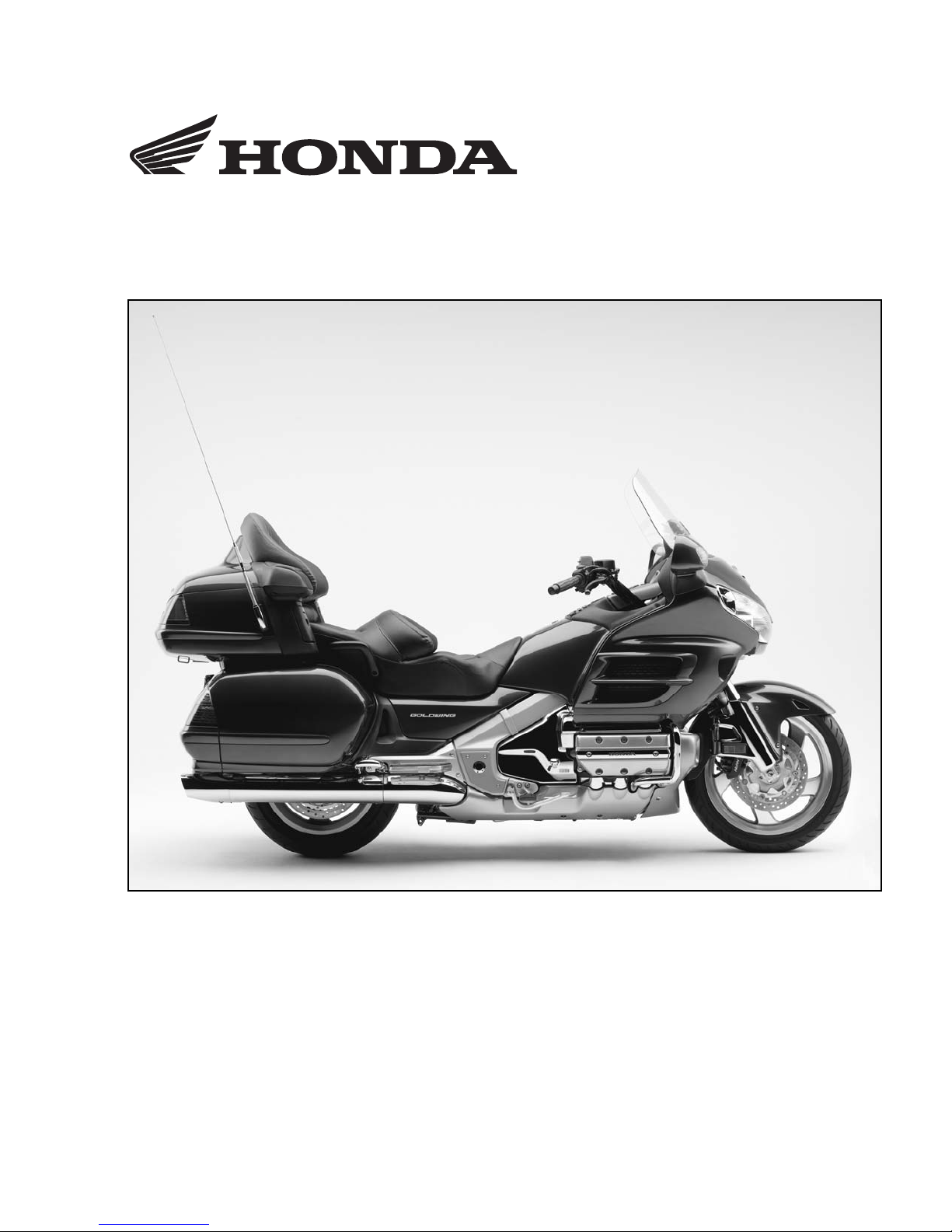
2005 GL1800/A
SET-UP
INSTRUCTIONS
Set-up and pre-delivery service
must be performed by an authorized
Honda motorcycle dealer.
©2004 American Honda Motor Co., Inc. - All Rights Reserved
MPD 10739 (0409)
Issued: September 2004
Page 2
IMPORTANCE OF PROPER SET-UP AND PRE-DELIVERY SERVICE
FOR YOUR CUSTOMER'S SAFETY
Proper set-up and pre-delivery service are essential to rider safety and the reliability of the
machine. Any error or oversight made by the technician assembling and servicing a new machine
can result in faulty operation, damage to the machine, or injury to the rider.
WARNING
Improper set-up or pre-delivery service can
create an unsafe condition that can cause
your customer to be seriously hurt or killed.
Follow the procedures and precautions in
this manual and the service manual carefully.
FOR YOUR SAFETY
Some of the most important safety precautions are given below. However, we cannot warn you of
every conceivable hazard that can arise in performing set-up and pre-delivery service. Only you
can decide whether or not you should perform a given task.
WARNING
Failure to properly follow instructions and
precautions can cause you to be seriously
hurt or killed.
Follow the procedures and precautions in this
manual carefully.
IMPORTANT SAFETY PRECAUTIONS
Make sure you have a clear understanding of all basic shop safety practices and that you are
wearing appropriate clothing and safety equipment. When performing the set-up or pre-delivery
service, be especially careful of the following:
• Read the instructions before you begin, and make sure you have the tools and skills required to
perform the tasks safely.
• To prevent the machine from falling on you, park it on a firm, level surface, using the proper
stand(s) to provide firm support.
Make sure the engine is off before you begin any servicing procedures. This will help eliminate
several potential hazards:
• Carbon monoxide poisoning from engine exhaust—be sure there is adequate ventilation
whenever you run the engine.
• Burns from hot parts—let the engine and exhaust system cool before touching.
• Injury from moving parts—do not run the engine unless the instruction tells you to do so.
Even then, keep your hands, fingers, and clothing away.
To reduce the possibility of a fire or explosion, be careful when working around gasoline or
batteries. Use only a nonflammable solvent, not gasoline, to clean parts. Keep all cigarettes,
sparks and flames away from the battery and all fuel-related parts.
©2004 American Honda Motor Co., Inc. - All Rights Reserved i
Page 3

2005 GL1800/A
How To Use This Manual
Follow the complete sequence of steps as shown. Do not short-cut any steps. The sequence has
been established to ensure the unit is properly assembled.
The individual steps are composed of three components:
• Sub-heading—The large sub-headings are a brief description of the step. They are intended
to be used by the experienced technician, one who only needs a brief reminder of the
set-up sequence.
• Descriptive text—The descriptive text explains in detail what is to be done during that step.
This explanation is intended as a guide for the technician needing additional information.
• Photographs/Line art—The photographs or line art support both the sub-headings and the
detailed text.
Indicates the Set-up section Indicates the Pre-delivery section
Modifications and Accessories
Modifications that you may have made, or should make in the future, to any Honda product, shall
be deemed by our company to have been performed at your sole risk and responsibility, and
without our company's or the manufacturer's approval, or consent, implied or expressed. We
further disclaim any and all liability, obligation, or responsibility for any defects of modified parts
or of the modified product, and for any claims, demands, or causes of action for damage to
property or for personal injuries resulting from the modification of said Honda product.
Revised Pages Torque Table
PAGE REVISED ITEM SIZE TORQUE
Seat bolts 8 mm 27 N·m (2.7 kgf·m, 20 lbf·ft)
Final drive oil check cap 8 mm 19 N·m (2.0 kgf·m, 14 lbf·ft)
ii ©2004 American Honda Motor Co., Inc. - All Rights Reserved
Page 4
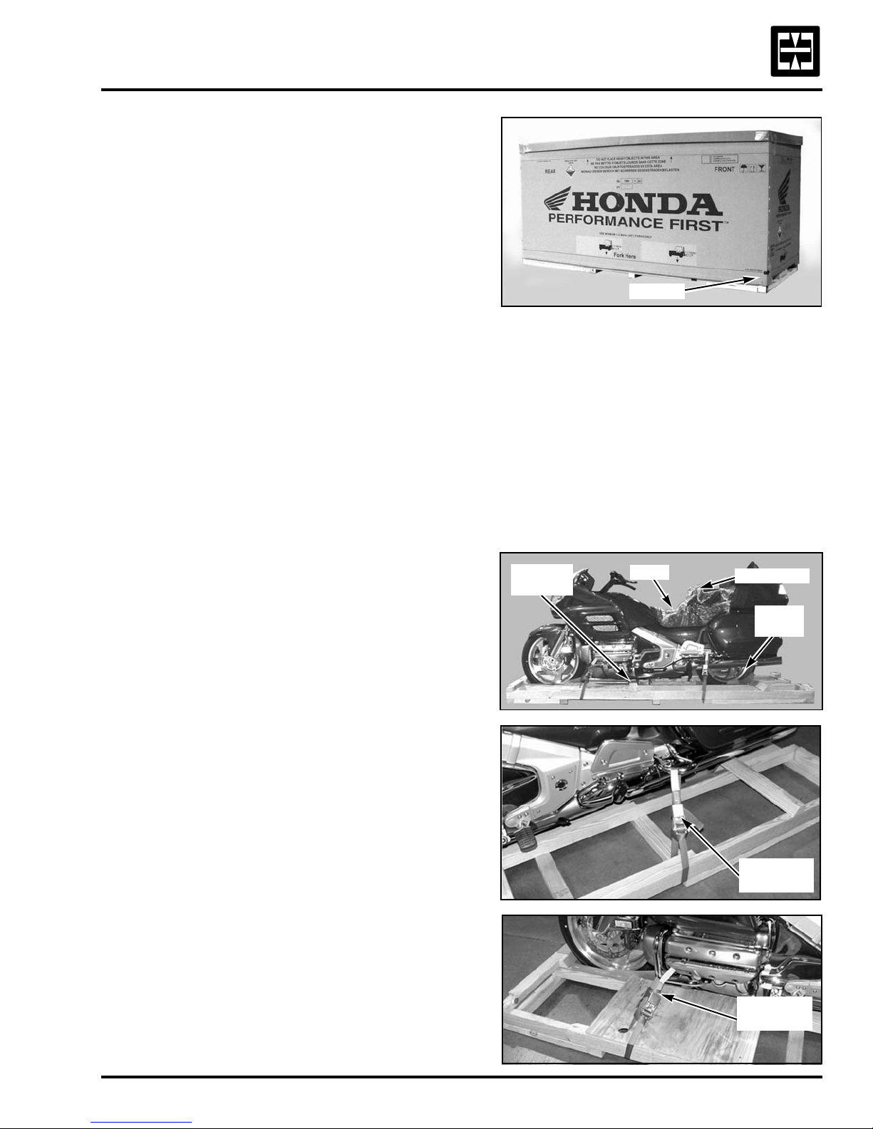
1. Remove the carton cover.
Pull the zip tab to separate the carton cover
from the crate base. Use short pulls (4 to 5
inches) parallel to the floor.
2. Check for damage.
Check the unit for damage.
If you find damage, follow the instructions on
the Delivery and Damage Claims Guidelines
wall chart (Reorder No. S0477) before
proceeding further.
3. Remove the loose parts.
Turn the carton cover over and remove the
windshield box from the inside top of the
carton cover.
Remove the loose parts bags from the left
saddlebag, the electrolyte from the tail trunk,
and the mirrors from the right saddlebag.
Keep the Owner’s Manual and the You and
Your Motorcycle Riding Tips & Practice Guide
booklet separate and hand-deliver to the
customer at the time of delivery.
4. Remove the motorcycle from the
crate frame.
Remove the seat and rear backrest.
CROSS
SUPPORT
ZIP TAB
SEAT
BACKREST
REAR
CHOCK
Remove the wood screws and the lower
cross support.
Remove the screws and the rear wheel chock.
Support the motorcycle and release
the tie-downs.
Roll the motorcycle backward, off the
crate frame.
©2004 American Honda Motor Co., Inc. - All Rights Reserved 1
TIE DOWNS
(Both sides)
TIE DOWNS
(Both sides)
Page 5
2005 GL1800/A
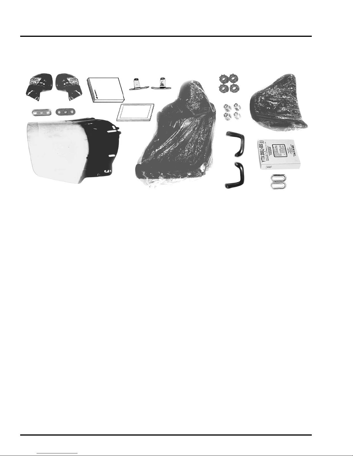
5. Loose Parts Information.
Unpack the remaining loose parts and check them against the parts list and this illustration.
7.
1.
3.
5.
2.
6.
4.
9.
10.
DESCRIPTION QTY PART NUMBER STEP
1. Mirror, R assembly 1 88110-MCA-A00 8
2. Mirror, L assembly 1 88120-MCA-A00 8
Note: Add color code to end of mirror part number.
Yellow: ZG, Red: ZM, White: ZQ, Silver: ZR, Blue: ZT, Gray: ZU
3. Holder, shield, A 1 64547-MCA-000 7
4. Holder, shield, B 1 64548-MCA-000 7
5. Windshield 1 64100-MCA-A20 7
6. Owner's Manual* 1 31MCA640 3
7. Stay, cowl, R 1 64257-MCA-000 8
8. Stay, cowl, L 1 64267-MCA-000 8
9. Tips & Practice Guide** 1 *G0045 3
10. Seat
Flame red 1 77200-MCA-A20ZB 6
All other colors 1 77200-MCA-A20ZA 6
11. Rubber, seat 4 77215-MCA-000 6
12. Collar, seat 4 90504-MCA-000 6
13. Grip, passenger, R 1 84150-MCA-000ZA 6
14. Grip, passenger, L 1 84155-MCA-000ZA 6
15. Backrest
Flame red 1 77500-MCA-A20ZB 6
All other colors 1 77500-MCA-A20ZA 6
8.
11.
12.
13.
14.
(Continued on next page)
15.
16.
17.
*If missing, order from Helm Inc. **If missing, order from Resolve Corp. (formerly DDS)
2 ©2004 American Honda Motor Co., Inc. - All Rights Reserved
Page 6
5. Loose Parts Information (cont.).
DESCRIPTION QTY PART NUMBER STEP
16. Electrolyte 1 ------------------------------ 11
17. Plate, shield 2 64116-MN5-000 7
18. Attaching parts (not shown):
Bolt, socket 8 x 70 mm 4 96600-08070-17 6
Screw, pan. hd. 6 x 8 mm 1 93500-06080-0H 7
Screw, special 5 x 12 mm 2 90104-964-000 8
Screw, self tap 5 x 16 mm 2 93903-25380 6
Screw/washer 5 x 20 mm 6 93891-05020-08 8
Screw, pan.hd. 6 x 11 mm 2 90106-KY2-701 7
Screw, special 6 x 12 mm 2 90103-HC4-770 7
Washer, plain 5 mm 2 94103-05700 6
Washer, nylon 8 mm 2 90507-921-0004 7
Missing Parts or Shipping Damage
Identify missing parts by referring to the “Loose Parts Information” section. Order the parts
using normal parts ordering procedures. Claims for missing loose parts or those damaged
during transit should be submitted to American Honda, not the carrier. After completing
repairs, submit a Transportation Claim via iN. For complete details, please refer to the
Warranty Policy and Procedures Manual.
©2004 American Honda Motor Co., Inc. - All Rights Reserved 3
Page 7
2005 GL1800/A
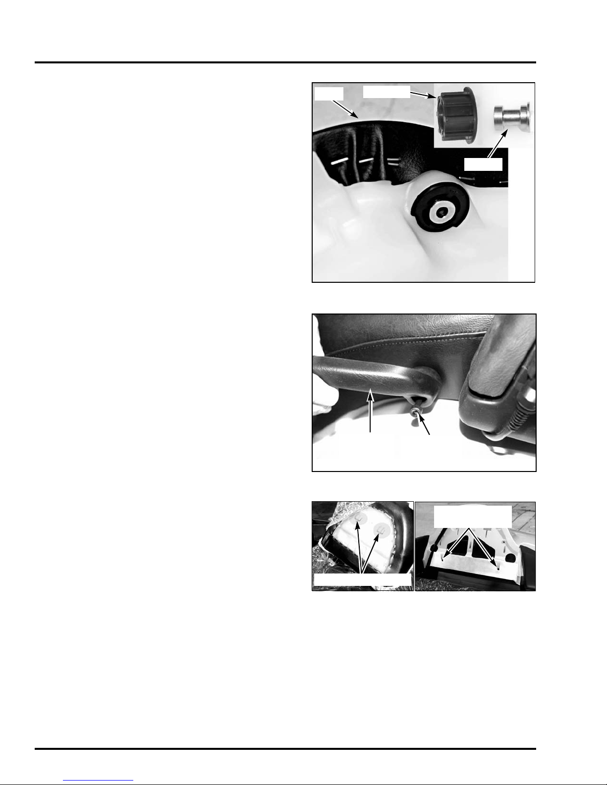
6. Attach the seat, passenger grips, and
back rest.
Insert the collars into the seat mounting
grommets with the larger diameter flange
opposite the flange on the grommet. Do this
for all four grommets.
Insert a seat grommet into each of the
mounting holes in the seat. Be sure the
portion of the grommet without the flange is
positioned toward the seat base.
Remove the protective plastic from the seat
and position the seat on the motorcycle by
slipping the front prong under the frame stay
and the two upper tabs into the slots in the
upper shelter.
Before attaching the seat, thread the seat
mounting bolts into the frame to be sure
the threads are clean. If the bolts do not
thread in easily, clear the threaded hole with
an 8 mm x 1.25 thread tap.
SEAT
GROMMET
COLLAR
Attach the passenger grips and the seat to the
motorcycle using two 8 x 70 mm socket bolts
on each side. Torque the bolts.
Torque: 28 N·m (2.7 kgf·m, 20 lbf·ft)
Slide the backrest retainers into the trunk lid
slots and open the trunk lid.
Attach the backrest to the trunk lid using two
5 x 16 mm self-tapping screws and washers.
PASSENGER
GRIP
BACKREST RETAINERS
8 x 70 mm
SOCKET BOLT
(2 each side)
5 x 16 mm SELF
TAPPING SCREWS
4 ©2004 American Honda Motor Co., Inc. - All Rights Reserved
Page 8
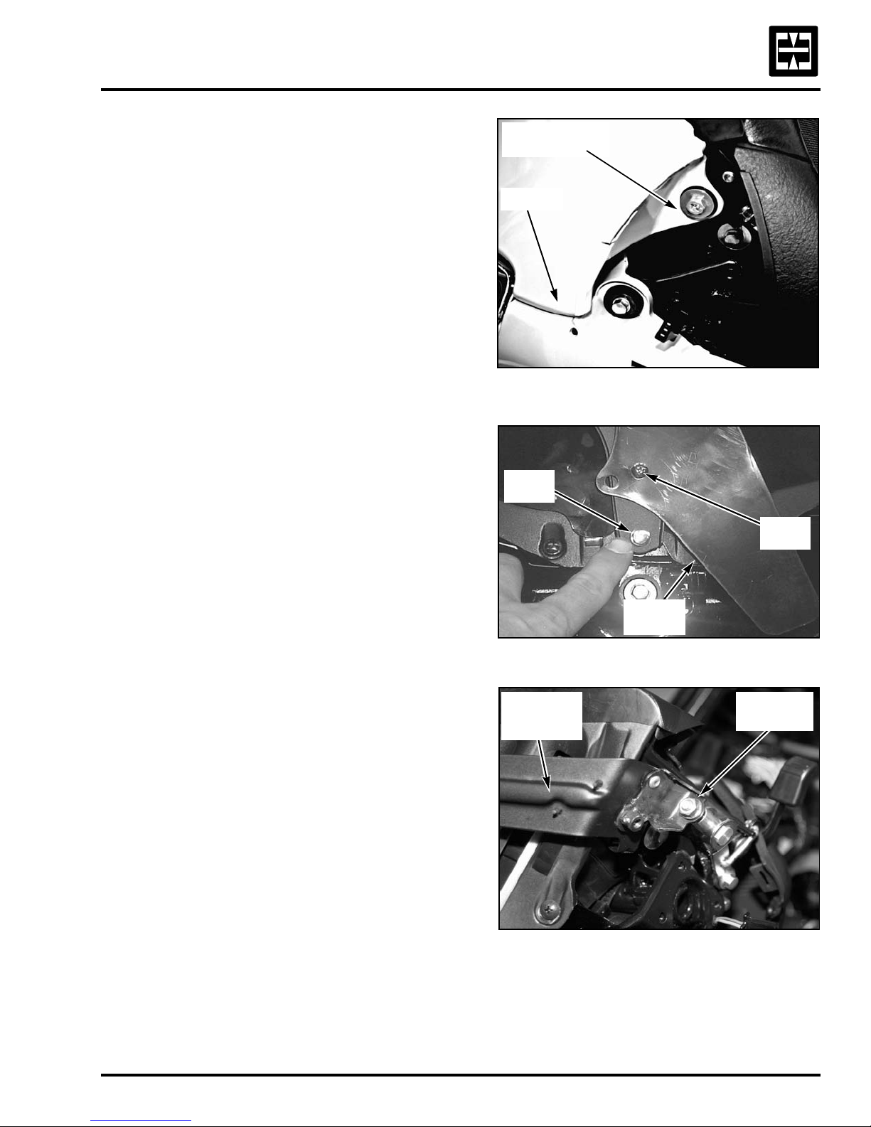
7. Install the windshield.
Remove a bolt, washer, and grommet from
each side of the garnish. Carefully pull the
garnish studs (four places) from their
grommets and remove the garnish.
Loosen the 5 mm cross-recess screw and
rotate the air vent cover to access the small
head windshield holder mounting bolt.
Remove the small head 6 mm windshield
holder bolt.
BOLT, WASHER,
and GROMMET
GARNISH
6 mm
BOLT
5 mm
SCREW
Remove the two 6 mm nuts (one each side)
attaching the windshield holder to the
windshield locking mechanism and remove
the holder.
WINDSHIELD
LOC KING
MECHANISM
AIR VENT
COVER
6 mm NUT
(EACH SIDE)
©2004 American Honda Motor Co., Inc. - All Rights Reserved 5
Page 9
2005 GL1800/A
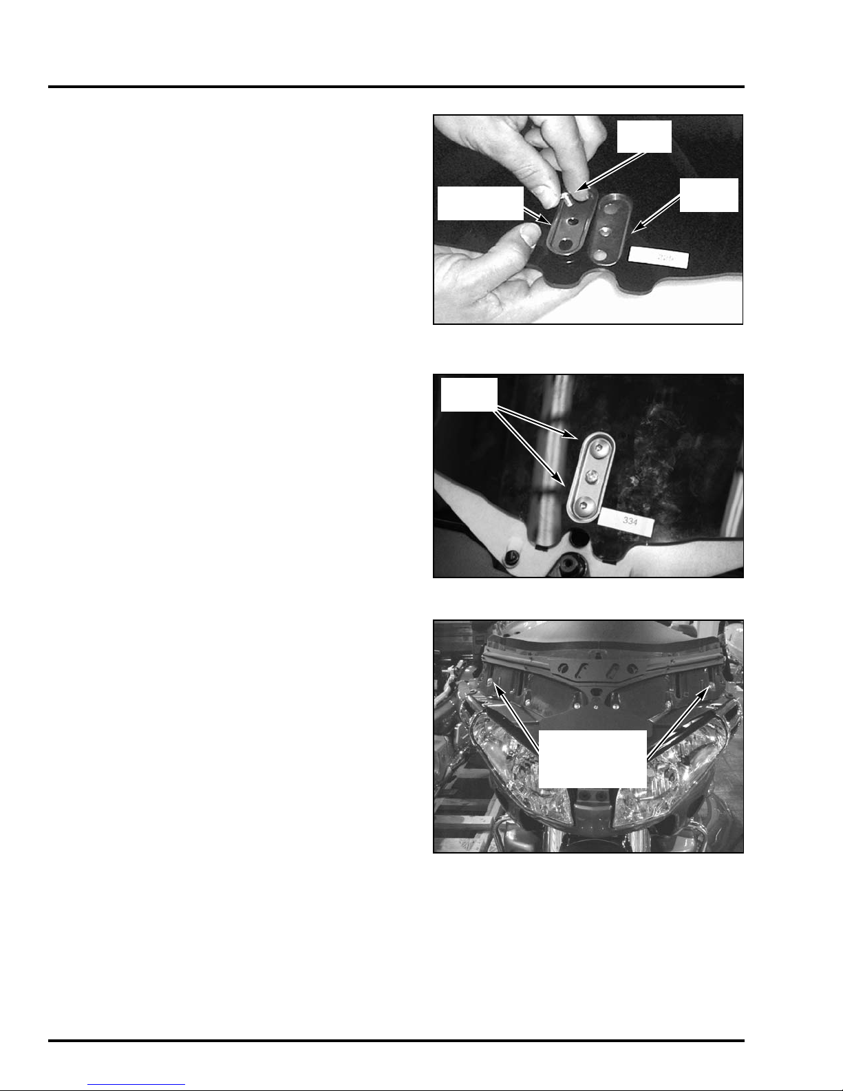
7. Install the windshield (cont.).
Assemble the center adjustment plate and
backup plate onto the windshield using a
6 x 8 mm screw.
Set the windshield in place on the fairing
and begin the installation by installing the
two 6 x 11 mm special screws in the center
adjustment plate.
ADJUSTMENT
PLATE
SPECIAL
SCREWS
6 x 8 mm
SCREW
BACK UP
PLATE
Place an 8 mm nylon washer on both
6 x 12 mm special screws. Install the outer
adjustment plates and attach them using
the special screws and washers.
ADJUSTMENT
PLATE and
6 x12 mm
SPECIAL SCREWS
6 ©2004 American Honda Motor Co., Inc. - All Rights Reserved
Page 10

7. Install the windshield (cont.).
Be sure that the windshield holder locator tab
is hooked over the fairing tab.
Attach the windshield holder with the small
head 6 mm bolt and two 6 mm nuts (one on
each side).
Tighten the bolt and nuts.
Rotate the air vent cover so that it is parallel to
the bottom edge of the fairing and tighten
the screw.
HOLDER
LOCATOR
6 mm
BOLT
FAIRING
TA B
6 mm NUT
(EACH SIDE)
Reinstall the garnish by carefully pressing the
lower mounting studs into their grommets (a
little soapy water will help).
Attach the garnish using the two bolts,
washers and grommets removed at the
beginning of the installation.
WINDSHIELD
GARNISH
GROMMET
STUDS
COLLARS
GROMMET
BOLTS
©2004 American Honda Motor Co., Inc. - All Rights Reserved 7
Page 11
2005 GL1800/A
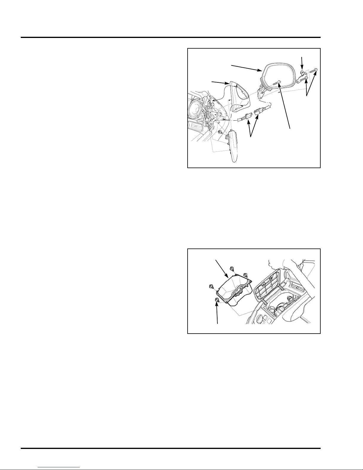
8. Install the mirrors.
Installation of the mirrors includes installing a
stay for the inner cowling on both sides. The
right-hand stay is marked with an “R”.
Mount each stay on top of the mirror mount.
Loosely install the mirror assembly (on both
sides) using a 5 x 20 mm screw/washer in the
top mounting hole.
Set a cowl stay (be sure of the correct side)
on the top of the lower mirror mounts and
attach the mirrors using two 5 x 20 mm
screws and washers.
Attach the inner cowling to the cowl stay
using a 5 x 12 mm special bolt (both sides).
Connect the turn signal connectors
(on both sides).
Repeat the procedure for the opposite side
and tighten all six screws.
Lubricate the mirror boot tabs with soapy
water and press them into place (two at the
top and three at the bottom) in the garnish.
MIRROR
BOOT
MIRROR
TURN SIGNAL
CONNECTORS
COWL STAY
5 X 20 mm
SCREWS
5 X 20 mm
SCREW
9. Install the auxillary input patch cord.
A length of wire is enclosed with the
Owner’s Manual pouch. This wire is a
patch cord that owners can use to attach a
personal stereo (CD player, MP3 player, etc.)
to the motorcycle.
Remove the left hand fairing pocket to reveal
the wiring boot where the headset DIN
connector is plugged. Contained within the
boot is a white three-pin connector to be used
with the patch cord. Run the wire through the
bottom of the fairing pocket with the enclosed
grommet; the cord can then be plugged into
the headset outlet of the personal stereo. This
allows the personal stereo to be played
through the motorcycle’s external speakers or
optional headsets.
LEFT FAIRING POCKET
TRIM CLIPS
8 ©2004 American Honda Motor Co., Inc. - All Rights Reserved
Page 12
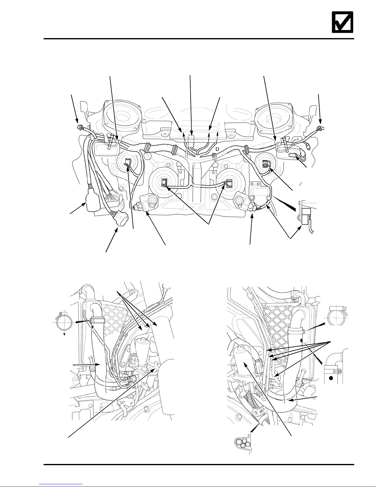
10. Check that the cables, hoses, and wire harnesses are properly routed.
TURN SIGNAL/
RUNNING LIGHT
CONNECTORS:
Rider headset
Auxilary input
Optional for
accessory socket
LEFT FRONT
SPEAKER WIRE
LEFT PANEL
SWITCH
To m et e r ( 1 6P
Black and 20P
Black connectors)
HIGH BEAM
HEADLIGHT
CONNECTOR
POSITION
LIGHT RELAY
HEADLIGHT
ADJUSTING
MOTOR
To t u rn s ig na l
relay (in meter) 3P
connector
LOW BEAM
HEADLIGHT
CONNECTORS
RIGHT FRONT
SPEAKER WIRE
HEADLIGHT
ADJUSTING
MOTOR
TURN SIGNAL/
RUNNING LIGHT
AMBIENT AIR
TEMPERATURE SENSOR
HIGH BEAM HEADLIGHT
CONNECTOR
BANK
ANGLE
SENSOR
RADIATOR
HOSE (LH)
FRONT
ABS
MODULATOR
FRONT
BRAKE
LINES
REAR
BRAKE
LINES
RADIATOR
HOSE
REAR ABS
MODULATOR
©2004 American Honda Motor Co., Inc. - All Rights Reserved 9
Page 13
2005 GL1800/A
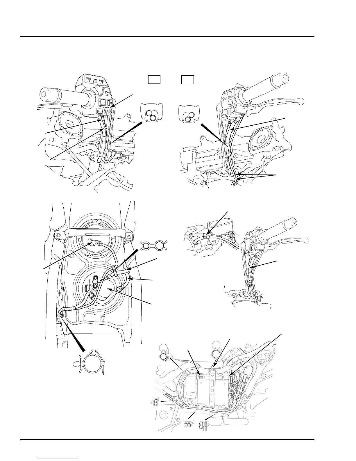
10. Check that the cables, hoses, and wire harnesses are properly
routed (cont.).
CLUTCH
HOSE
CLUTCH
SWITCH
WIRE
SWITCH
HARNESS
LH
RH
BRAKE
HOSE
THROTTLE
CABLES
THROTTLE ADJUSTER
FUEL
LEVER
SENSOR
FUEL LINE
(SUPPLY)
FUEL LINE
(RETURN)
FUEL PUMP
NEGATIVE (-)
CABLE &
TERMINAL
BATTERY STAY BOLT
SWITCH
HARNESS
POSITIVE (+)
CABLE &
TERMINAL
BATTERY
BOLT
10 ©2004 American Honda Motor Co., Inc. - All Rights Reserved
Page 14
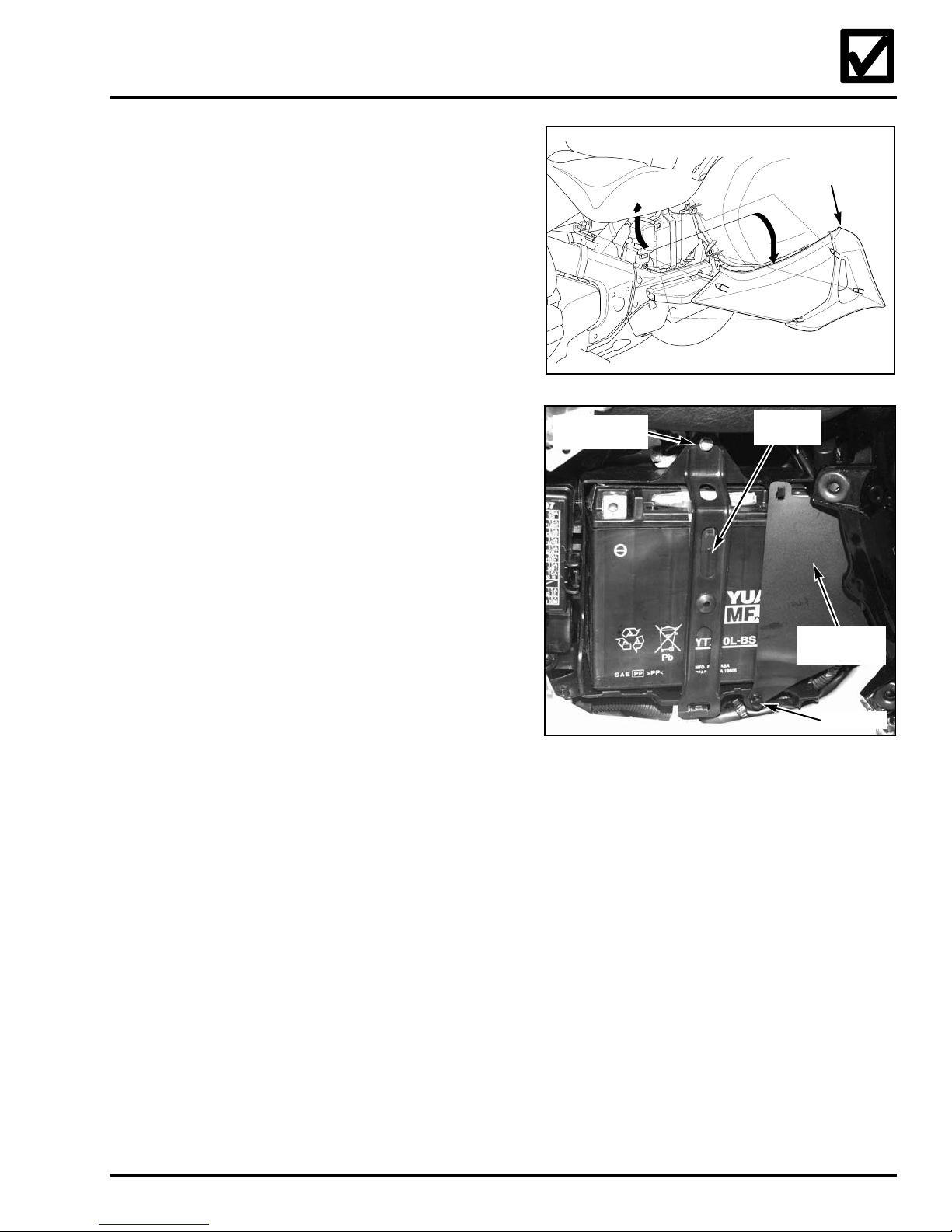
11. Service the battery.
Service and install the battery in the
motorcycle only if the unit has been sold or
will be used as a demonstrator.
Remove the battery from the motorcycle
before filling it with electrolyte. Spilled
electrolyte can damage frame and body parts.
Remove the left side cover.
LEFT
SIDE
COVER
Remove the push-pin by pulling the stem out.
Remove the protective cover.
Before removing the battery holder bolt, place
a folded shop towel over the frame rail below
the battery holder to prevent any contact
between it and the frame.
Remove the battery holder bolt. Lower the
battery stay onto the shop towel and remove
the battery.
Service the battery according to Service
Letter #48 and the instructions on the
electrolyte container.
Slide the battery terminal nuts into the battery
terminals. Set the battery in the battery
compartment. Connect the positive (+) battery
cable to the positive (+) battery terminal and
the negative (-) battery cable to the negative
(-) battery terminal using the terminal bolts.
Tighten the bolts securely, coat the terminals
with dielectric grease, and pull the red cover
over the positive terminal.
BATTERY
HOLDER BOLT
BATTERY
HOLDER
PROTECTIVE
COVER
PUSH PIN
Raise the battery holder into position and
attach it using the 6 mm bolt previously
removed. Tighten the bolt securely.
Hook the battery cover in place and secure it
with the push-pin.
Make sure the positive (+) battery cable is not
resting on any metal parts. Prolonged wear
could cut through the insulation and cause a
short circuit. Replace the protective cover and
secure it with the push-pin.
Using soapy water to lubricate the rubber
grommets, carefully replace the side cover.
©2004 American Honda Motor Co., Inc. - All Rights Reserved 11
Page 15
2005 GL1800/A
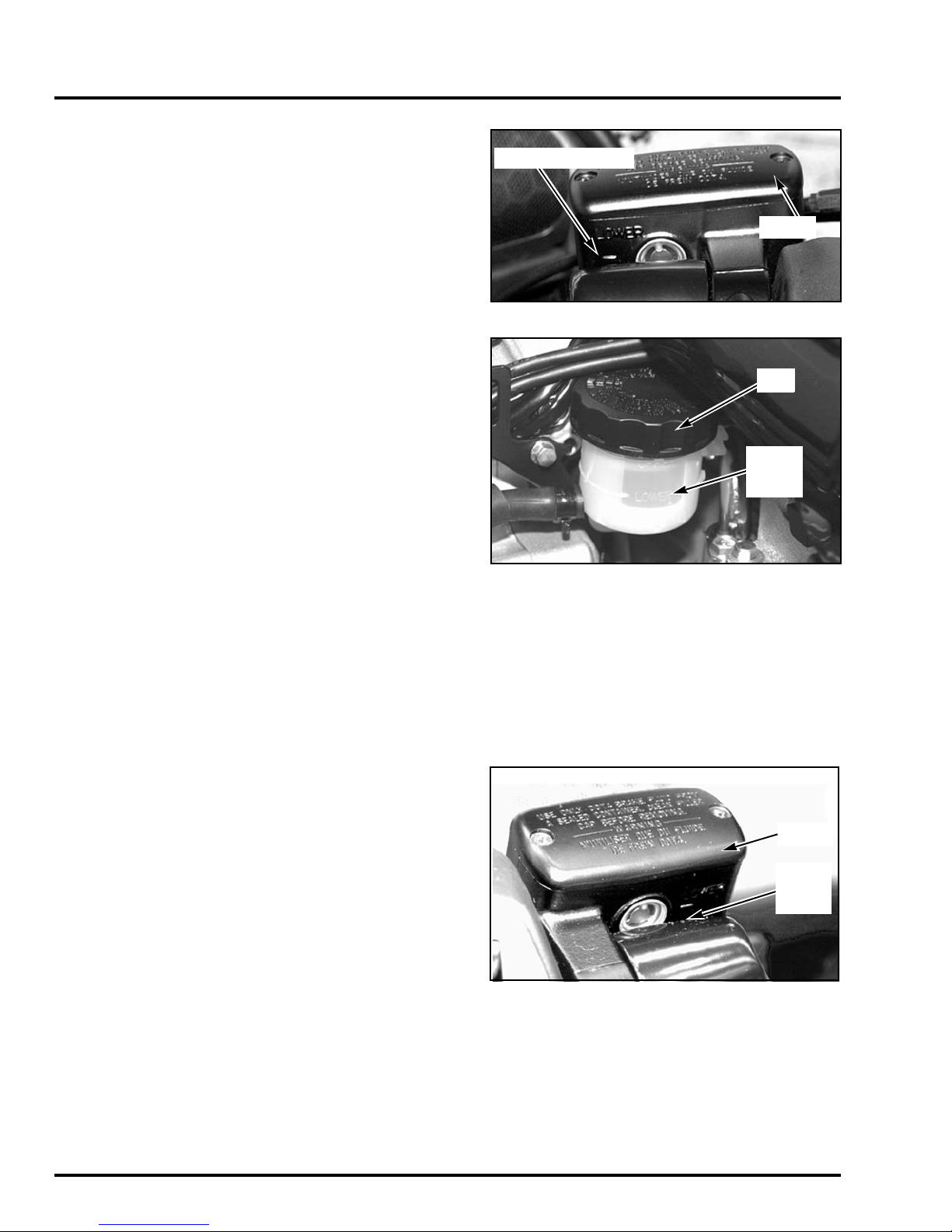
12. Check the fluid level in the front and
rear brake reservoirs.
Turn the handlebar so that the front brake
reservoir is level and check the fluid level.
Remove the right engine cowl to access the
rear brake reservoir and check the fluid level.
Keep the engine cowl off until the completion
of step 15.
LOWER LEVEL MARK
COVER
CAP
If the level is below the lower level mark,
remove the cover and diaphragm or cap. Add
Pro Honda DOT 4 or equivalent brake fluid
from a sealed container.
Reinstall the diaphragm and cover or cap.
Tighten the screws securely.
Operate the brake lever and pedal. If the free
play is excessive and the reservoir is filled to
the correct level, bleed the brake system.
Handle brake fluid with care as it can damage
painted surfaces and plastic components.
This type of hydraulic disc brake requires no
free play adjustment.
13.Check the clutch master cylinder.
Turn the handlebar so that the clutch reservoir
is level. Check the fluid level.
Operate the hand lever. If the free play is
excessive, bleed the system.
If the fluid level is low, remove the
reservoir cap and diaphragm by removing
the two screws.
LOWER
LEVEL
MARK
COVER
LOWER
LEVEL
MARK
Add Pro Honda DOT 4 or equivalent brake
fluid from a sealed container to bring the level
up to the upper level mark. Install the
diaphragm, cover, and screws.
This type of hydraulic system requires no free
play adjustment.
12 ©2004 American Honda Motor Co., Inc. - All Rights Reserved
Page 16
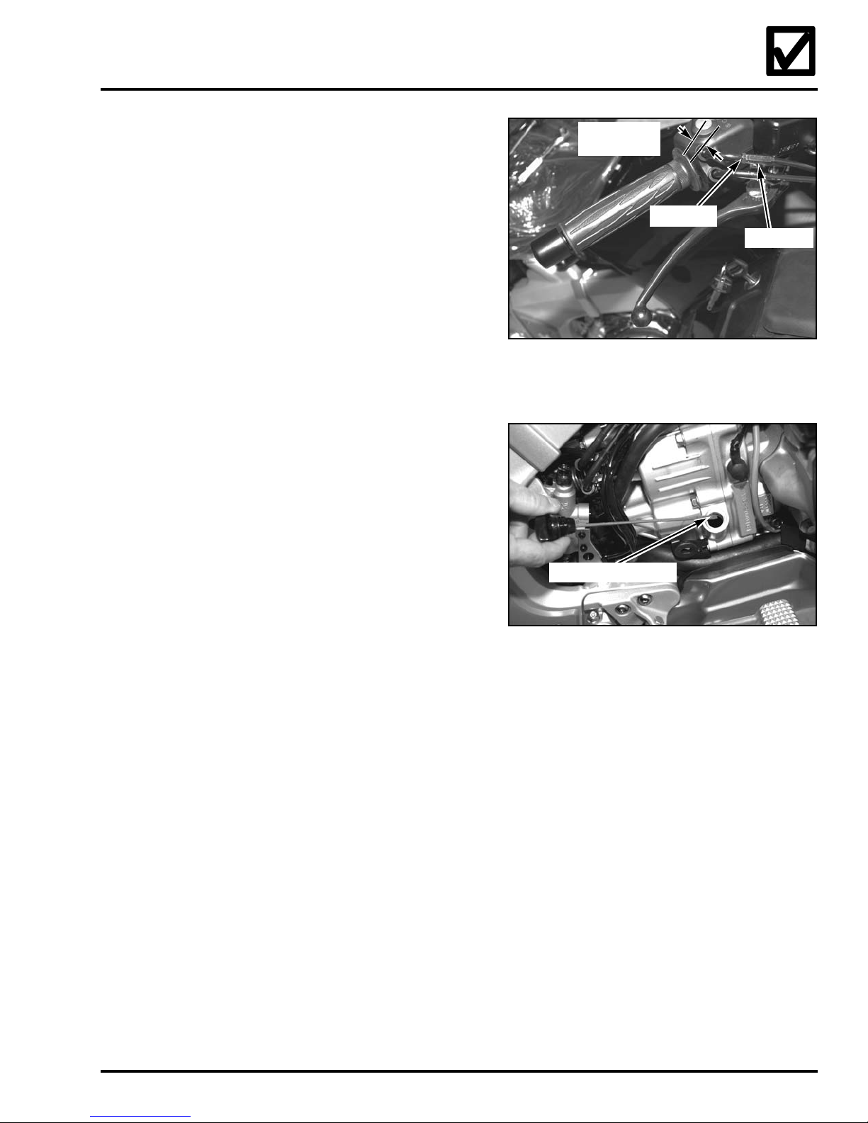
14. Check the throttle free play.
Check the throttle cables for damage.
Operate the throttle. Confirm that it moves
smoothly and returns from any open to the
fully closed position, automatically, in all
steering positions.
Confirm the throttle grip free play.
Throttle grip free play:
3 - 6 mm (1/8 - 1/4 in.)
Free play adjustments are made at the throttle
grip adjuster by loosening the lower lock nut
and turning the adjuster. Tighten the lock nut
after making the adjustment.
15. Check the oil level.
Before starting the engine, remove the antirust compound by washing the engine and
exhaust system with mild detergent and
water. Rinse with clean water.
3-6 mm
(1/8 - 1/4 in.)
LOCK NUT
ADJUSTER
Place the motorcycle on its centerstand on a
firm, level surface. Remove the right engine
side cover.
Remove the oil filler cap/dipstick and wipe
it clean. Insert the dipstick until it seats, but do
not screw it in. Remove the dipstick and check
the oil level. If the level is low, add oil as
needed to bring the level above the lower
level mark.
• Oil recommendation: Pro Honda HP4 or
GN4 (without molybdenum additives)
4-stroke oil or equivalent.
• Viscosity: SAE 10W-40
• API Classification: SG or higher. Do not
use oils labeled as energy conserving
on the circular API service label
• JASO T 903 standard: MA
• Crankcase capacity: 3.6 liters
(3.8 U.S. quarts)
Replace the oil filler cap/dipstick.
LOWER LEVEL MARK
©2004 American Honda Motor Co., Inc. - All Rights Reserved 13
Page 17
2005 GL1800/A
15. Check the oil level (cont.).
Start the engine and let it idle for 3 - 5
minutes. Make sure the low oil pressure
indicator goes off. If the indicator remains on,
stop the engine and troubleshoot the cause.
Stop the engine and wait 2 - 3 minutes.
Recheck the oil level using the above
procedure and, if necessary, add the
recommended oil until it reaches the upper
level mark.
Reinstall the right engine cover removed in
step 12.
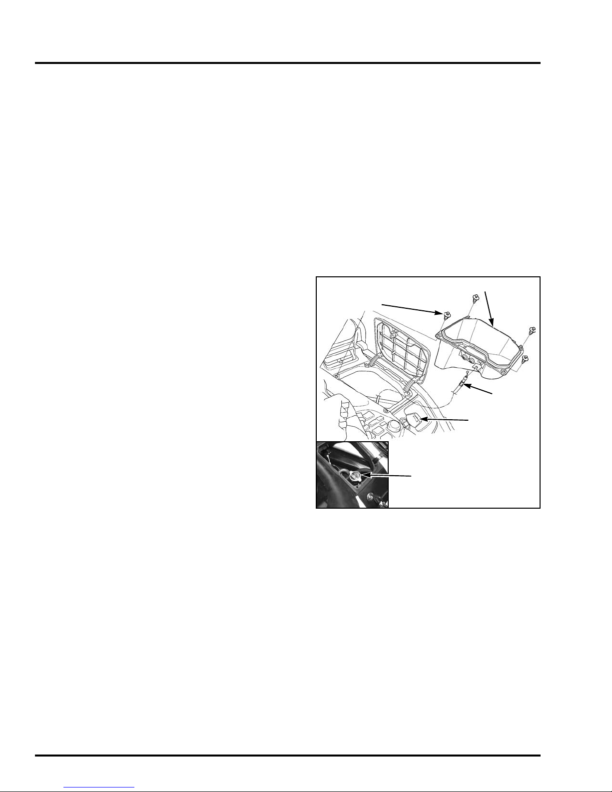
16. Check the coolant level.
Remove the left engine cover and the
coolant reserve tank cap/dipstick. Check
the coolant level.
If required, add Pro Honda coolant (premixed) or a 1:1 mixture of anti-freeze and
distilled water to restore the level to the upper
level mark.
If it is necessary to add coolant to the radiator,
unlock the right hand fairing pocket using the
ignition key.
Unlock the four pocket retainer clips by
pressing the center pin in with a small
screwdriver. Carefully remove and save the
four clips.
Lift the pocket out of the fairing and remove
the latch cable by pulling the cable housing
down and out of its anchor tab.
Do not spill coolant on any painted or plastic
surfaces, as it may damage the finish.
RIGHT FAIRING POCKET
TRIM CLIPS
OPENER
CABLE
IGNITION KEY
RADIATOR CAP
14 ©2004 American Honda Motor Co., Inc. - All Rights Reserved
Page 18
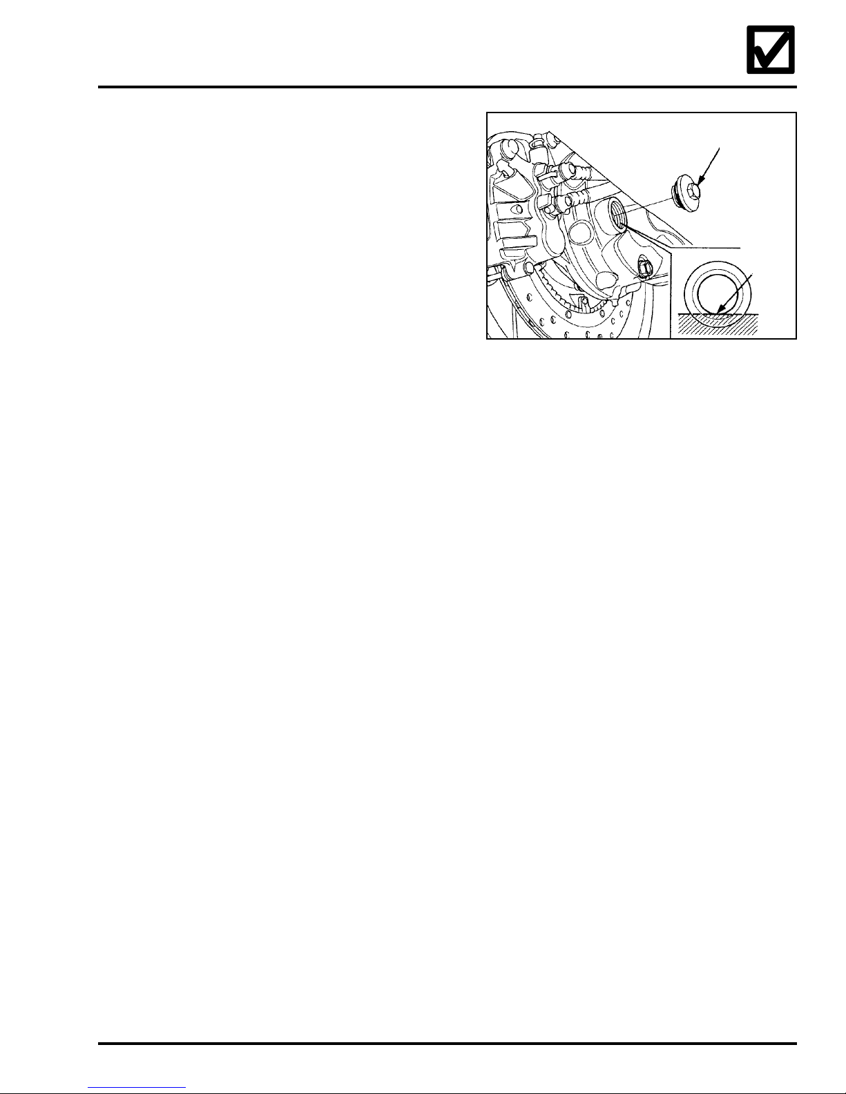
17. Check the final drive gearbox
oil level.
Support the motorcycle on its centerstand on
a firm, level surface.
Remove the oil level check cap from the final
reduction gear box. Check the oil level. It
should be flush with the lower edge of the oil
filler hole. If the level is low, add the
recommended oil until it reaches the lower
edge of the opening.
Recommended oil: Pro Honda Shaft
Drive Oil or equivalent Hypoid gear
oil (SAE 80).
Install and torque the oil check cap.
Torque: 19 N·m (2.0 kgf·m, 14 lbf·ft)
18. Clean the brake discs and
the motorcycle.
Clean the anti-rust coating off all three brake
discs with Pro Honda Brake Cleaner or
equivalent and a clean shop towel.
OIL LEVEL
CHECK CAP
LOWER
EDGE
19. Initialize the ECM.
The GL 1800 uses an electronically controlled
IAC (Intake Air Control Valve) to minimize
idle fluctuations normally caused by air
temperature and load variations.
Idle Speed: 700
In order for the IAC to operate properly,
the ECM (Engine Control Module) must
be initialized.
Start the engine and let it warm up to normal
operating temperature.
Once normal temperature is achieved, allow
the engine to idle, without touching the
throttle, for at least 90 seconds. If the throttle
is operated during this time, the ECU will not
initialize properly and the process will need to
be repeated. Idle speed should stabilize at
± 50 rpm.
700
± 50 rpm
©2004 American Honda Motor Co., Inc. - All Rights Reserved 15
Page 19

2005 GL1800/A
20. Check the tire pressure.
Front: 36 psi
Rear: 41 psi
21. Complete the Set-up/Pre-Delivery
Checklist.
Complete an On-Road Motorcycle Set-up/
Pre-delivery Checklist (Reorder No. S0299) by
checking the boxes confirming that the steps
were done.
16 ©2004 American Honda Motor Co., Inc. - All Rights Reserved
Page 20
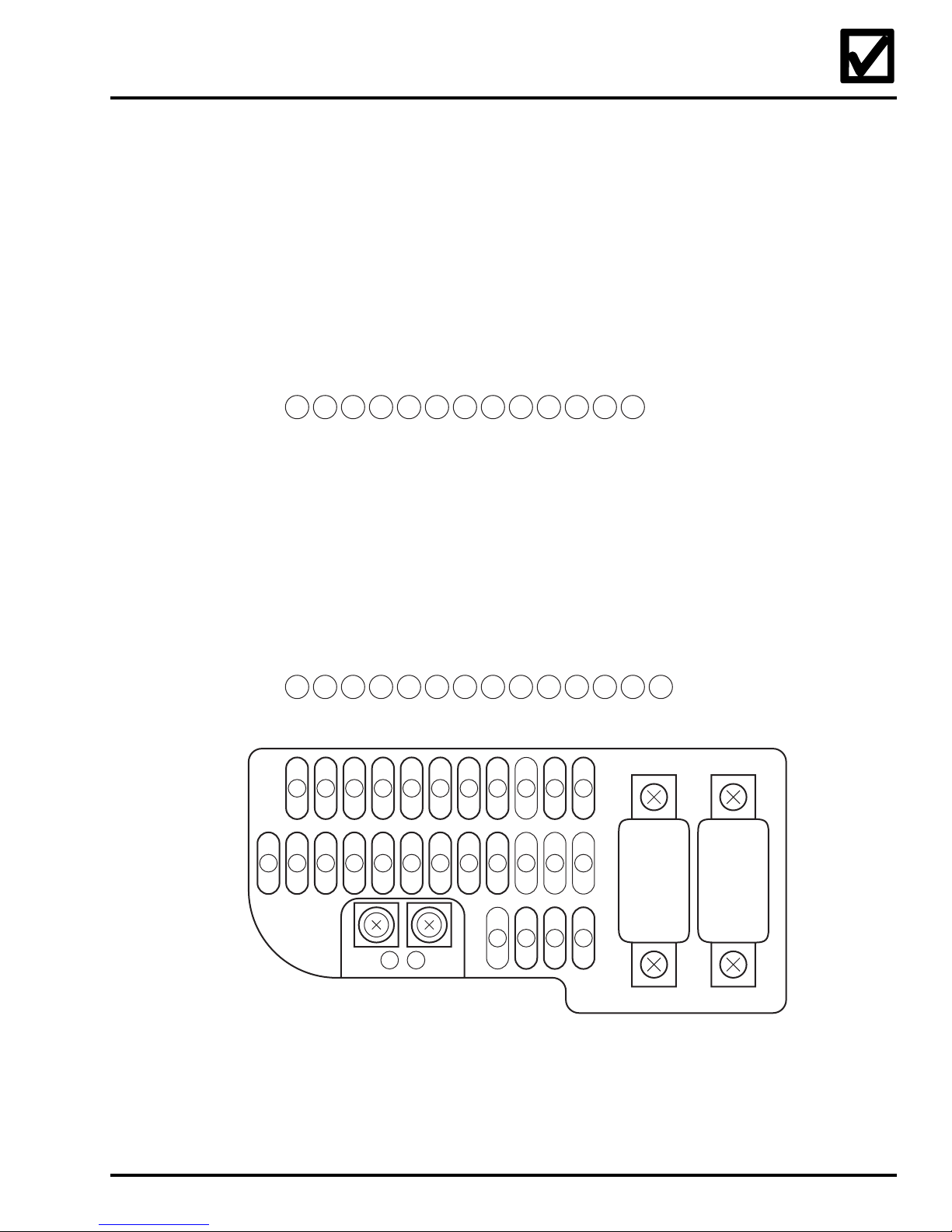
Fuse Box
Not used
Not used
15
16
FI IGN FUSE
STOP LIGHT FUSE
IGN CRUISE FUSE
SUSP LEVEL FUSE
17
18
19
20
AUDIO/ACC FUSE
BATTERY FUSE
RVS SHIFT FUSE
HEAD HI FUSE
21
22
23
24
Not used
HEAD LO FUSE
HORN TURN FUSE
25
26
27
Not used
1
17
6
5
FUSE BOX
MAIN FUSE A
ABS MTR FR FUSE
ABS MTR RR FUSE
2
3
4
18
19
20
9
8
7
+
ACC
TERMINAL
TAIL FUSE
ACC. TERM. FUSE
FAN FUSE
5
6
7
21
22
23
12
11
10
–
ST. KILL FUSE
HEAD RLY FUSE
RVS START FUSE
8
9
10
24
25
26
15
14
13
1
2
3
RVS FUSE A
RVS FUSE B
ABS MAIN FUSE
11
12
13
27
16
MAIN FUSE B
4
Not used
14
100 A
SPEED LIMITER
FUSE 70 A
©2004 American Honda Motor Co., Inc. - All Rights Reserved 17
Page 21
2005 GL1800/A
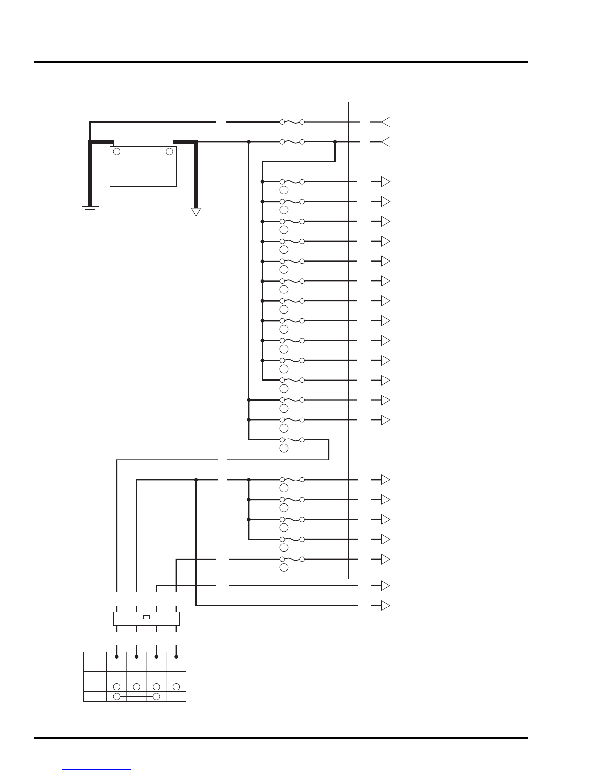
Fuse Box - Wire Routing
FUSE BOX
Y
–
BATTERY
+
STARTER RELAY
SWITCH A
SPD LIMIT FUSE 70 A
MAIN FUSE B 100 A
15 A
5
20 A
17
15 A
18
15 A
19
15 A
20
15 A
21
20 A
22
15 A
23
10 A
24
15 A
26
15 A
27
30 A
3
30 A
4
Y
W
W/Y
Bl
W/R
Y
Br
Lg
R/Y
R/Bl
W/Bu
W/Y
Bl/W
R/Bu
R/G
SPEED LIMITER RELAY
ALTERNATOR
TAIL LIGHT RELAY
FI/IGNITION RELAY
STOP LIGHT RELAY
IGNITION CRUISE RELAY
SUSPENSION LEVEL MAIN RELAY
ACCESSORY RELAY
TRUNK LOCK CONTROL SYSTEM
AUDIO SYSTEM
COMBINATION METER (BACK-UP)
REVERSE SHIFT RELAY 1
HEADLIGHT HI RELAY
HEADLIGHT LO RELAY
HORN/TURN RELAY
ABS MOTOR DRIVER (FVBM)
ABS MOTOR DRIVER (RVBM)
LOCK
OFF
ON
ACC
R
Bl
R
Bl
IGNITION SWITCH
Lg/Bl
Lg/Bl
Bu/O
4P W
Bu/O
R
Bl
Bu/O
Lg/Bl
30 A
2
10 A
8
10 A
9
5 A
10
5 A
13
20 A
7
W
Br/R
Br
R/Bu
Bl/Bu
Lg/Bl
Bl
IGNITION SYSTEM
HEAD ADJUSTER RELAY
STARTER/REVERSE SWITCH
STARTER/REVERSE SYSTEM
ABS CONTROL UNIT (MAIN)
FAN CONTROL RELAY
ACCESSORY RELAY
HORN TURN RELAY
TAIL RELAY
18 ©2004 American Honda Motor Co., Inc. - All Rights Reserved
Page 22
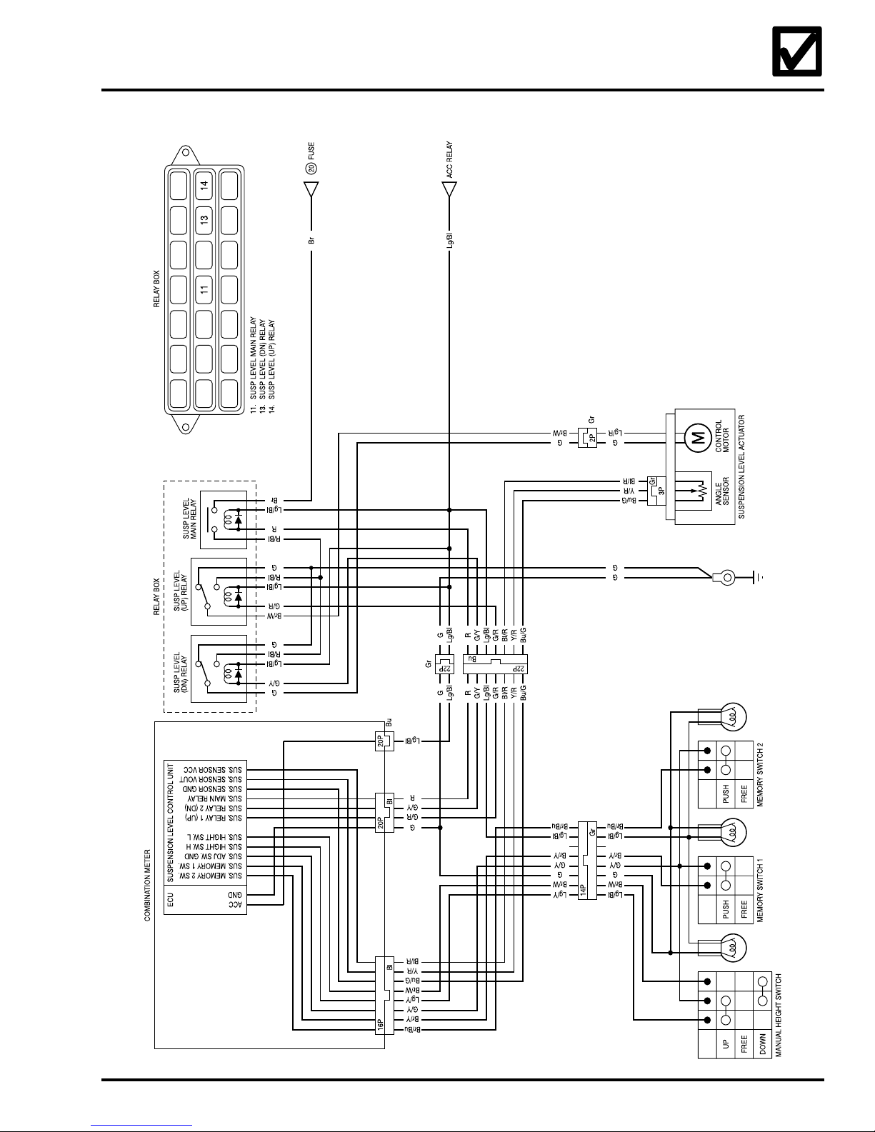
Suspension Level Control
©2004 American Honda Motor Co., Inc. - All Rights Reserved 19
Page 23

2005 GL1800/A
ABS
20 ©2004 American Honda Motor Co., Inc. - All Rights Reserved
Page 24
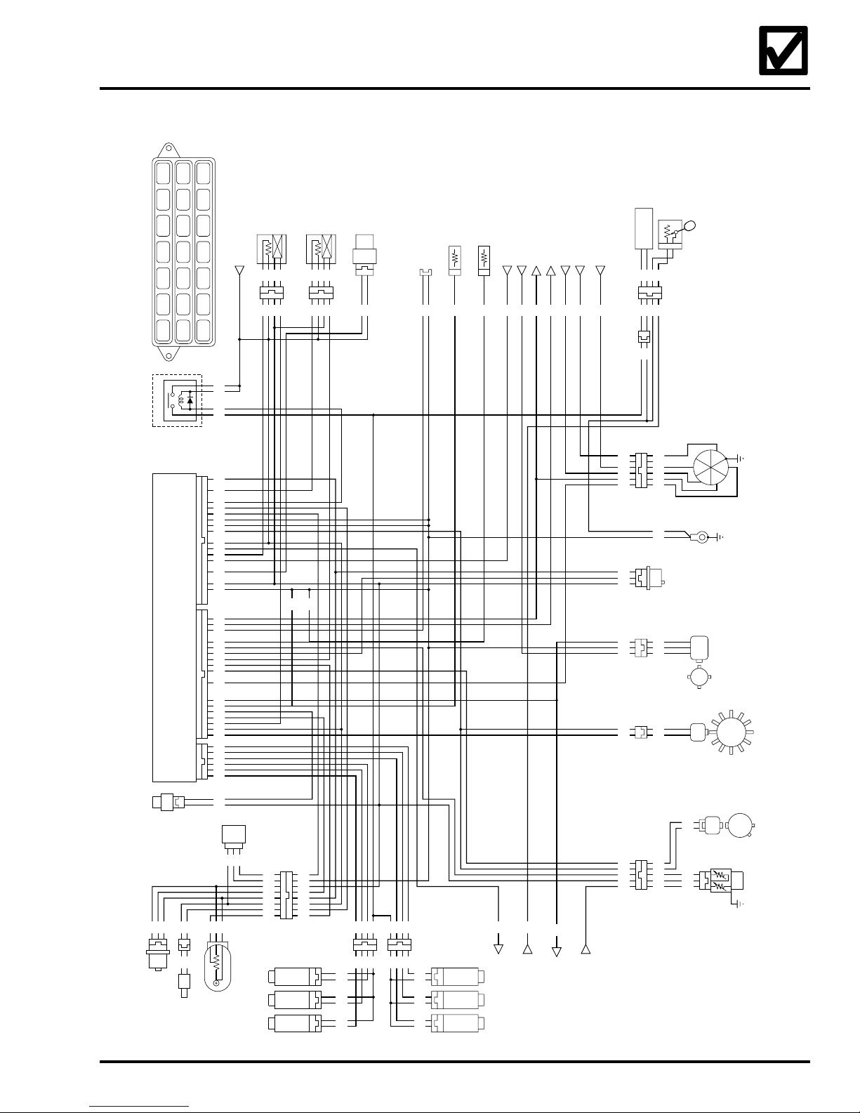
Fuel System
RELAY BOX
RELAY BOX
IAT SENSOR
G/R
3P Gr
4
FUEL PUMP RELAY
ENGINE CONTROL MODULE
2P Bl
Y/R
Lg/Y
MAP SENSOR
O/G
Bl/Y
O/G
Bl/Y
PAIR CONTROL
SOLENOID
VCC
IMMO IND
HTCNTL2
FANR
FLR
EX-AI
RACV
LG
PG2
PCM
IGPLS3&4
IGP
22P Bl22P Gr6P Bl
WARN
HTCNTL 1
ACGF
IDC
PCS
IMOAU
SG
PG1
IGPLS5&6
IGPLS1&2
RXD-TXD
GP3
NLSW
SCS
IMOID
KNOCK 2
TW
PA
O2-2
THL
CYLP
TACHO
GP2
S STAND
VSP
KNOCK 1
TA
PB
O2-1
IMOV
PCP
INJ6
INJ4
INJ2
INJ5
INJ3
INJ1
2P W
VALVE
CONTROL
IDLE AIR
Lg
G/O
TP SENSOR
2
RIGHT O SENSOR
FI/IGNITION RELAY
W
W
Gr
G/R
Bl/YWBl/R
4. FUEL PUMP RELAY
Bl/Y
Bl/Y
Br/Bl
Br
Y/R
W
Br/Bl
O/G
Lb
G
G
W/Y
Bl/Y
W/Bu
W
Bl
Y/Bl
G/R
G
W/R
Bu/R
Br
Bu
Y/Bu
Lg/Bl
Bl/O
Lg
Gr
Bl/Y
W/Bl
R/Bu
Gr/Bu
Lg/Y
Bl/R
Bl/Y
Y
Lg
R/Bl
R/Y
P/W
R/Bl
P/Bu
Gr/Bu
G/R
VALVE
3P Gr
G
Lb
Bl/Y
LbLb
G
G/R
Lg/Y
Y/R
Bl/Y
O/G
Lg
Y/R
3P Bu
2
CONTROL
VALVE
SOLENOID
EVAP PURGE
LEFT O SENSOR
SERVICE CHECK
CONNECTOR
3P Bl [MINI]
G
Br
Br
Lg
R/Y
R/Bl
4P
Gr Gr
Br
Lg
R/Y
P/Bl
Lg
Br
P/Bl
Br
R/Y
Br
2P Bl 2P Bl 2P Bl
4P Bl
2P Bl
Y/Bl
Bl/Y
Br
P/W
R/Bl
P/Bu
4P
P
Br
R/Bl
P/Bu
Br
P
Br
R/Bl
Br
P/Bu
Gr
MINI
S
W
W
S
G
G/R
Lg/Y
Y/R
Bl/Y
O/G
Lg
INJECTOR
No. 5 FUEL
2P Bl2P Bl
INJECTOR
No. 3 FUEL
INJECTOR
No. 1 FUEL
2P Bl
Bl
W
G/R Gr
Bl/Y
Bl/O
Bl
4P W
8P
LEFT KNOCK SENSOR
RIGHT KNOCK SENSOR
1P Bl
1P Bl
Bu
R/Bu
INJECTOR
No. 6 FUEL
INJECTOR
No. 4 FUEL
INJECTOR
MALFUNCTION INDICATOR LAMP
No. 2 FUEL
W/Bu
(MIL)
TAIL LIGHT RELAY
ALTERNATOR
Bl
Br/W
REVERSE REGULATOR ASSEMBLY
REVERSE REGULATOR ASSEMBLY
REVERSE REGULATOR ASSEMBLY,
W/R
Bu/R
Gr
W/Bl
FUEL LEVEL SENSOR
CRUISE/REVERSE CONTROL UNIT
COMBINATION METER
CRUISE/REVERSE CONTROL UNIT
R/W
REVERSE REGULATOR ASSEMBLY,
CRUISE/REVERSE CONTROL UNIT
Lg/R
COOLANT TEMPERATURE GAUGE
OVERDRIVE INDICATOR
REVESE REGULATOR ASSEMBLY,
CRUISE/REVERSE CONTROL UNIT
G/O
Y/R
G/R
G
W/Y
Y
Gr
W/Y
G/R
G/Bl
Lg/R
R/W
W/R
Bl/Y
Lg/Bl
W/Bl
Y/Bu
2P
6P
3P W
2P R
Gr
6P
FUEL PUMP
G
G
Br
G
G
Br
G
Br
BlMINI
3P Bl
[MINI]
[MINI]
MINI
Gr
5P Gr
Gr
Lg/R
G/O G/O
R/W
W/R
Bl/Y
G
G
W/Bl
G
Br Br/W
W/Y
Y
Gr
W
Y/Bu
G/R
G/Bl
FUEL LEVEL
SENSOR
BARO SENSOR
N
2
OD
3
4
2P Bl
Gr
W
3P
Y/Bu
G/R
G/Bl
VEHICLE
SPEED SENSOR
GEAR POSITION SWITCH
IGNITION PULSECAM PULSE
GENERATOR GENERATOR
ECT SENSOR
©2004 American Honda Motor Co., Inc. - All Rights Reserved 21
Page 25
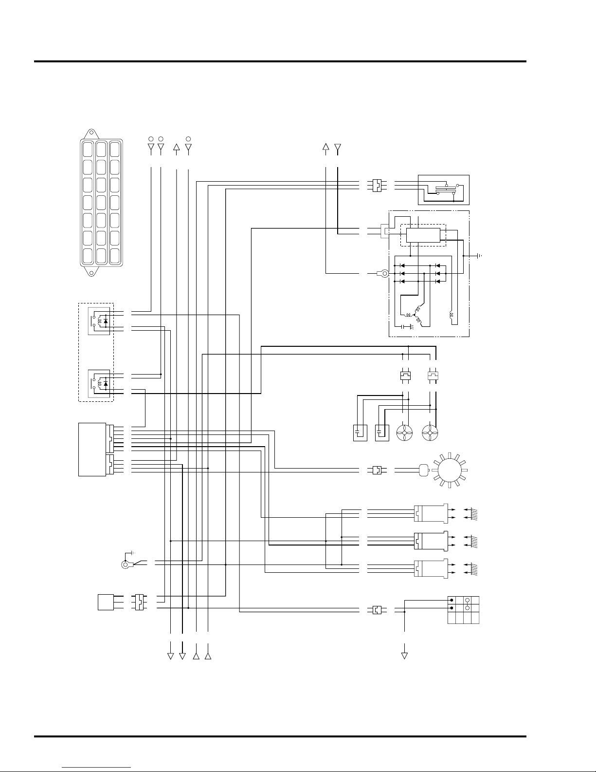
2005 GL1800/A
Cooling/Charging/Ignition System
FUSE
FUSE
FUSE
17
8
7
REVERSE REGULATOR
ASSEMBLY
IGNITION CRUISE RELAY
MAIN FUSE B
RELAY BOX
RELAY BOX
FAN CONTROL
ENGINE CONTROL MODULE
Bl/Bu
W
Bu/R
Bl
3
15
FAN CONTROL RELAY 3.
15. FI IGN RELAY
Bl
Bl/W
R/W
FANR
PCM
I GPLS3&4
I GP
ACGF
I GPLS5&6
I GPLS1&2
22P
NLSW
TACHO
SSTAND
PCP
22P
Bl/Y
Bl/Bu
Bl/Bu
Br/R
Bu
Br/R
W/Y
Bl
Y/Bu
Bl/Y
Bl
Y/R
Y/W
Bu/R
Gr
Y/G
G/W
Y
FI IGN RELAYRELAY
W
Bl/Y
[MINI]
3P G
Y/Bl
Y/Bl
G/W
G/W
G
G
SIDE STAND SWITCH
4P
FR
Bl
Bl/Y
W
[MINI]
R
W/Y
Y
2P
(L)
IG
IC
P
B
BuBu
2P W
Bl G
Bl
RIGHT FAN MOTOR
W/Y
Y
EF
LATOR
REGU-
ALTERNATOR
GBl
2P Bl
Bu Bu
Bl
LEFT FAN MOTOR
GENERATOR
IGNITION PULSE
G
G
GG
G
MINI
R/W
R/W
W
W
3P
SENSOR
ANGLE
BANK
Y/G
Y/Bl
Bl/Y
SIDE STAND INDICATOR
IGNITION CRUISE RELAY
FUEL SYSTEM
COMBINATION METER
CRUISE/REVERSE CONTROL UNIT
22 ©2004 American Honda Motor Co., Inc. - All Rights Reserved
G/W
CRUISE/REVERSE CONTROL UNIT,
CLUTCH SWITCH
G
Bl/Y
Y/W
Bl/Lg
Bl/W
Bl/W
STARTER/REVERSE SWITCH
4P Bl 4P Bl
4P Bl
COILS
IGNITION
SPARK
#5
#6 #2 #1#3#4
PLUGS
OFF
OFF
RUN
ENGNE STOP SWITCH
G
Bl/Y
Y/Bu
G
Bl/Y
Y/R
W
Bl/W
18P G
Page 26
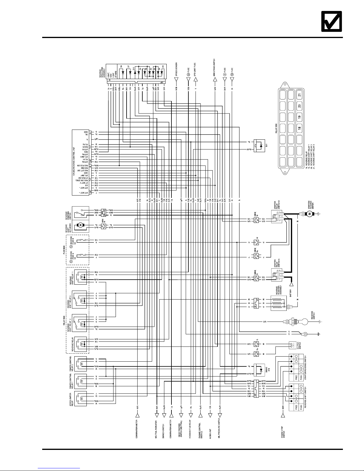
Starter/Reverse System
©2004 American Honda Motor Co., Inc. - All Rights Reserved 23
Page 27
2005 GL1800/A
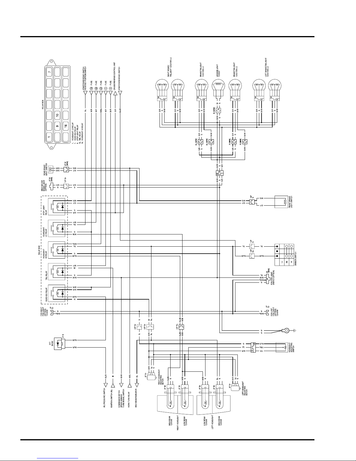
Lighting System
24 ©2004 American Honda Motor Co., Inc. - All Rights Reserved
Page 28
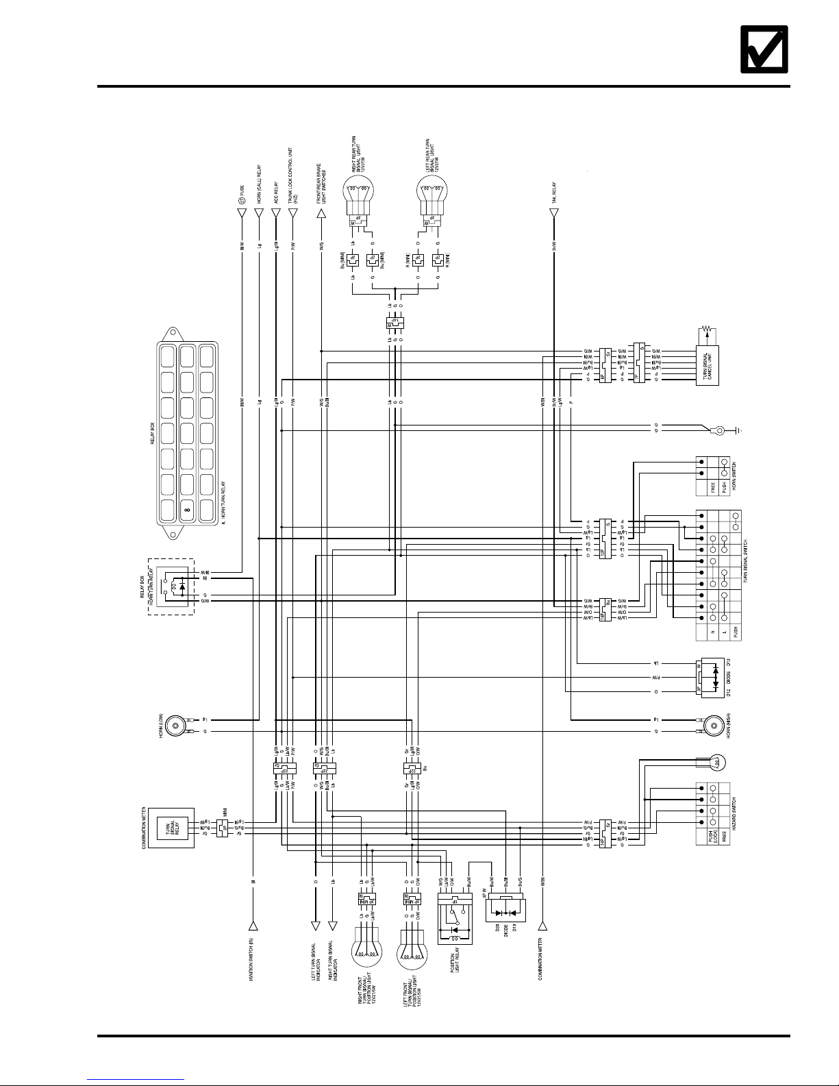
Turn Signal Lights/Horn
©2004 American Honda Motor Co., Inc. - All Rights Reserved 25
Page 29
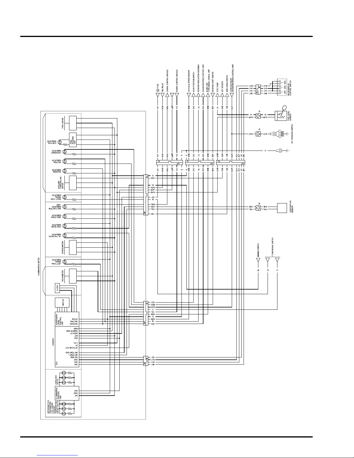
2005 GL1800/A
Combination Meter
ACCESSORY RELAY
AMBIENT AIR
DIGITAL
26 ©2004 American Honda Motor Co., Inc. - All Rights Reserved
Page 30
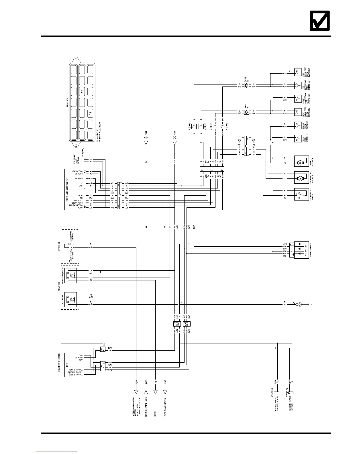
ACC/Trunk Lock System
©2004 American Honda Motor Co., Inc. - All Rights Reserved 27
Page 31
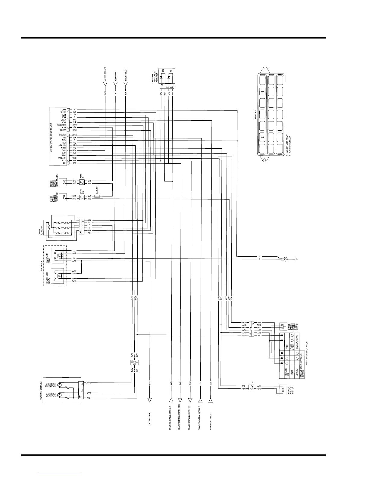
2005 GL1800/A
Cruise Control System
VEHICLE
28 ©2004 American Honda Motor Co., Inc. - All Rights Reserved
 Loading...