

Honda 175 (1971), CL175 K5 (1971) Owner's Manual
HONDA
MOTOR
CO.,
LT:D.
' '
175
i2
MODEL
K5
@
'70
: 12 @ A 5.
PRINTED
I)
I 4
IN
JAPAN
._._
. . . .
OWNER'S
--
Mi~UAL
C~175
....
'f'~
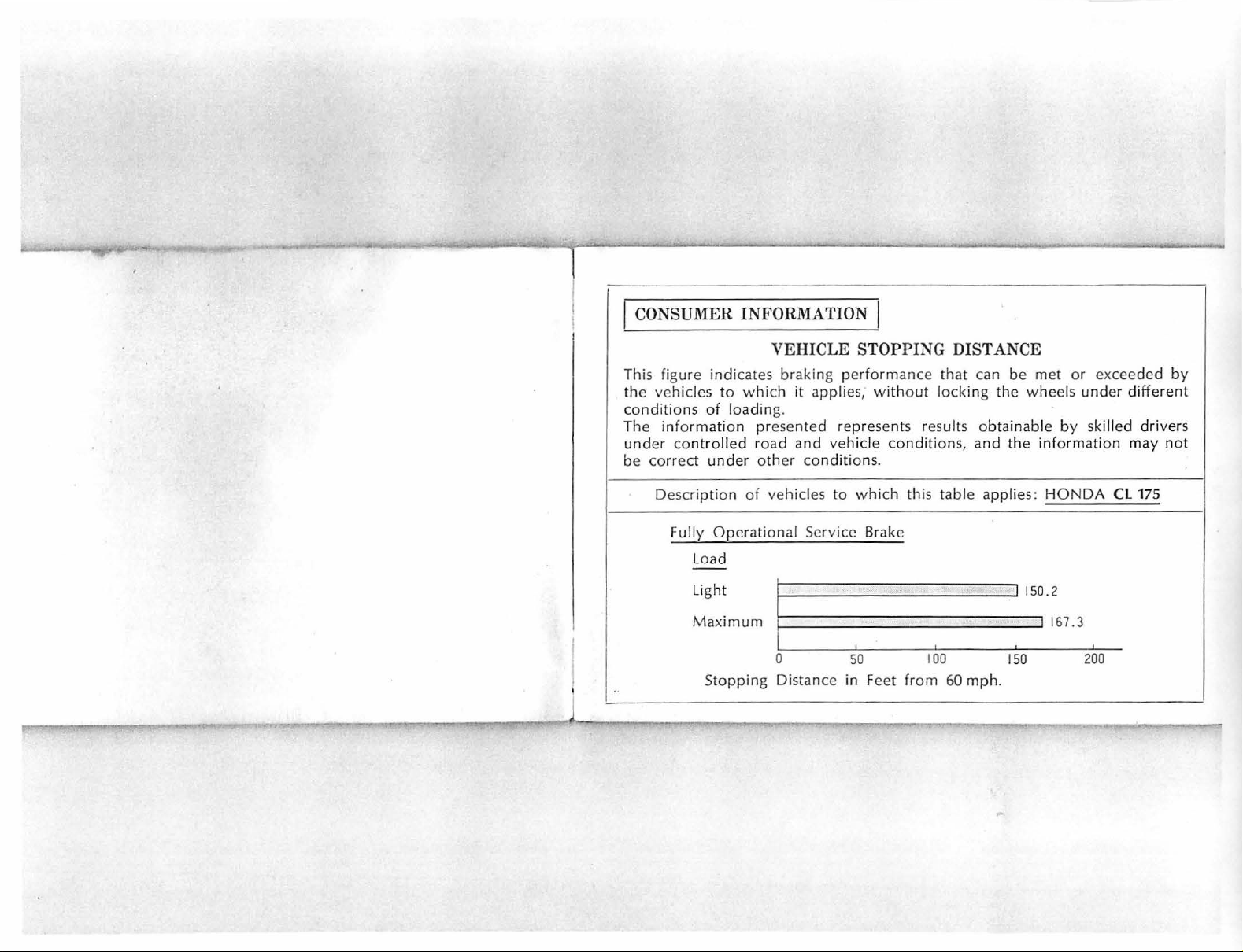
CONSUMER INFORMAT
ION
This figure indicates
the
vehicles
conditions
The
informat
under
be
correct
Description
Fully
..,,.
..,,.
to
which
of
loading.
ion presented re
cont
rolled
Load
Light
Maximum
Stopping Dista nce in Feet
road
under
other conditions.
of
Ope
rational Service Brake
VEHICLE
braking performance
it
and
vehicles
,__
_____________
0
STOPPING
applies, without
pre
sents results obtainable
vehicle
to
conditions
which
I I I
50
DISTANCE
tha t can
locking
this table applies:
1
00
from
60
be
the wheels
, and the information
150
mph
.
met
or
by skil
HONDA
_.I 167. 3
exceeded
under
led
CL 175
200
differen
dri
vers
may
not
by
t
1
...
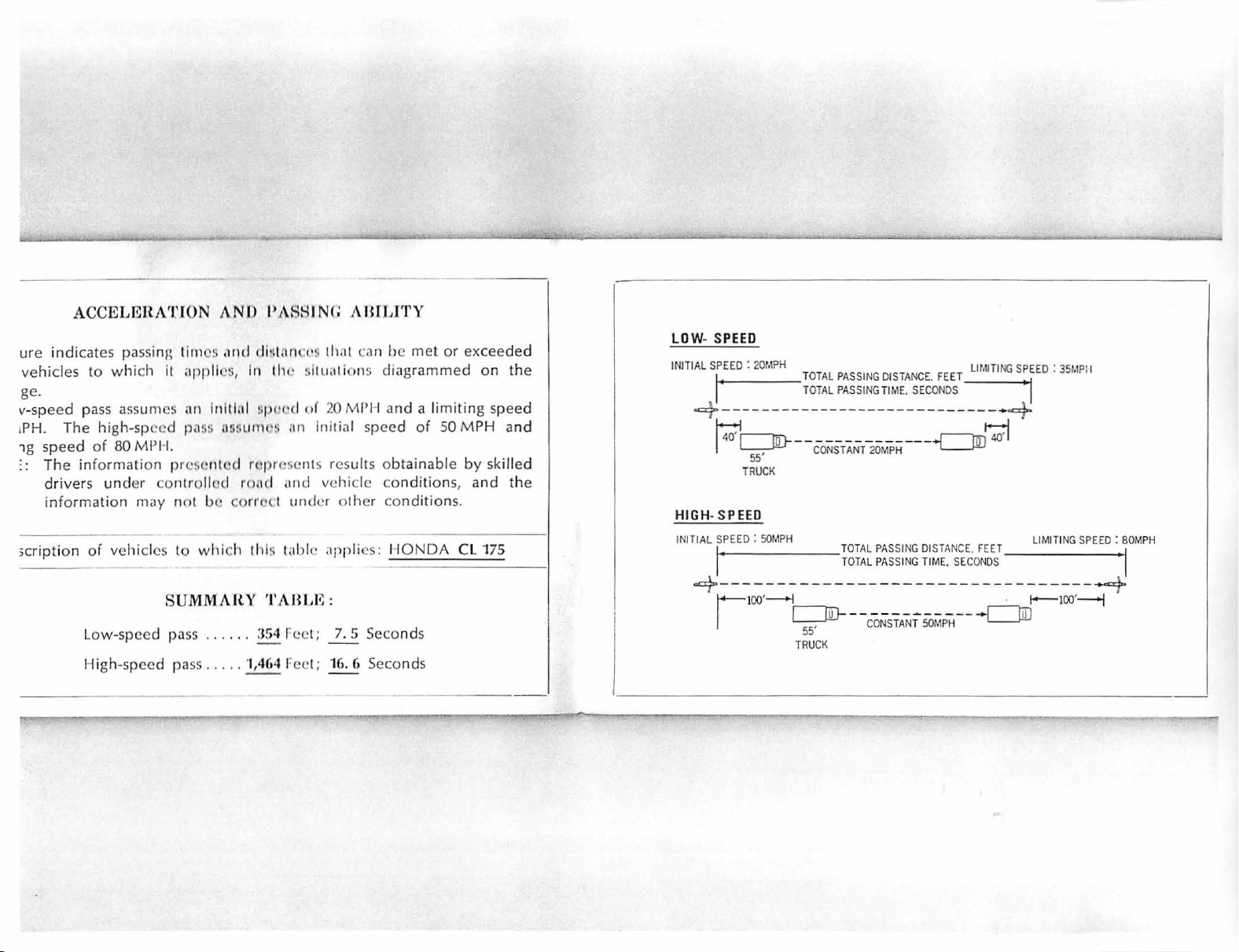
ACCELEHATJON A
ure indicates passing
vehicles
ge.
v-sp
1PH. The high-spe ed
1g speed
. . The infor
;cr
ipti
to
which
eed pass ass
of
80
mation prese
driv
ers
und
information
on
of vehicl
Low-speed
High-
speed pa
it ap
umes a
Ml'H
er co
may not L
es
SU
tim
es
,111d
pll
<.!
S, 111 1lw s
11 l11i
tl.il
pass
ns:wnw~
.
nted
ntr
ollod
H·
to
whi
ch
MMAltY
pass ......
ss
.....
NI)
I'
ARH
dl:n 1ncvs 1h.it c
~pt
t·d of
.
111
rcpn·scnts res
road
,111d
c
orr~rt
uncJt:r other
th
l~
table applies:
TABLI
:
J!i4 r-cc
·1,464 r-cc
I
NG
A BrLITY
an
!Jc
met
l1u,11i
ons diagr
20
MPH a
Initial speed
ult
s obtainable
vehicle co
~:
l ; 7. 5 Seco
l ; 16. 6 Seconds
ammed
nd
a l
of
ndi
con
ditions
HONDA
nd
s
or excee
imiting
50 M
tion
on
PH and
by
s,
and the
.
CL 175
ded
the
speed
skilled
LOW-
SPEED
INITIAL
SPEED : 20MPH
I'
-=}--
HIGH- SPEED
INITIAL
=}--
-------------- -------
14:':1~-
I
"u
I
55
TR
SPEED : 50MPH
--------------------------------
!
OO'
r
TOTAL PASSI
T
OTAL PASSING
-------------
,
UCK
-l
CONSTANT
c=:::JD-
,
55
TRUCK
TOTAL
TOTAL
LI
NG
DISTANCE. FEE
TIME. SECONDS
MITING
T • 1
- ----+
20MPH
PASSING DISTANCE. FEET
PASSING TIME,
------~---
CONSTANT
~~
"L__J.ILJ
SECONDS
---
50MPH
c=JD
SPEED : 35MPI
~
LIMITING SPEED
·
l--100'--j
I
...a}
: 80M
I
PH
11
11111111111111111111111111111111111111
Thank
175
The
t
motorcyc
HONDA
es
many new
you for
is produced
tion
techniques and test
at I
IONDA
motorcycle will
than
complete
manual has been
This
to the pr
© 1
970
HONDA
MOTOR
111111
le.
CL
employing
are
oper
CO
1111111
11111
11111
11111 111111 11111
purchasing
175
moto
and
special features
the
confident
provide
satisfaction.
prepared
operation
.• LTD
11
11111111111111
11~
FOREWORD
the
HONDA
rcycle
incorpora
latest
produc
equipment.
that
your
you
with
as
a g
and
serv
icing
CL
and
We
new
more
uide
of
11111
111111
yo
ur
new
Read the manual
maintain
sible
pleasure.
-
Your
wi
is
th
always
the
co
ndit
HONDA
complete
problem.
H
ONDA
miles
of
motorcycling.
111
11111111111
1111111111111
motorcycle.
motorcycle
io n· for the
dealer
periodic
happy
wishes
to assist
you
11111111111111111111
111
1111111111111111111111
tho
rou
ghly
in the best pos-
utmost
will
provide
maintenance
you with
many
safe
to
in
11111111111111
better
riding
you
and
any
happy
1
11111111111111111111111111111111111111111111111111111111
CAT
ION
SERIAL
tMENCLATURE
ERA
TING I
LECTRI
Instruments
Main
Headlight
Starter
Turn
Horn
t1ECHAN
S
teering Lock
Cl
utch Lever ...
F
ront
Rear Brake Pedal
Gea r
Choke Lever ...
UEL AND OIL
Fuel Va l
Fuel
NST
CAL
SYSTEM
Switch
Control
Butt
on ...
Signal Swit
Butt
on
ICAL
Brake Lever
Sh
ift Pedal
ve
...
Tan
k .
...
11
1111111111
NUMBEns
. . . . . .
..............
RUCTION
...............
and
Indi
cat
....................
Switch .......
..........
ch
...
...........
CONTROLS
...........
............
........
...
.........................
....
. . .........
...
. .
.......
..........
.....
..............
........
.......
. . .
111
11
CONTENTS
................
..
..............
or
Ltlllf>S ..•............
.
. . •. .
.
..........
...
........
.
....
............
........ • ....................
.
.....•
...
.....•........
.........
. . . . . ....
.. ..
. . . . . .
.........•.........
....
. .
..........
....... .
, •. .
.......
....
. . ....
........
. . .....
.......
....
.................
. . .
.......
...
. . .
111111111111
' .
..
...
...
. .
.......
..
.
.......
........
...
. .... . . . . .
...
........
.........
11111111
1111
1111
1111111111111
111111111
111111111111111111111111111111111111111111111111
' ' .
.. ' ..
....
...
....
...
...... .
• .. ....
...........
. . . ....... . . .... .
....
..........
. .
.............
..........
. . .
......
...........
• .. . .
.....
...........
......
........
.....
...
.................
. .
...
......
...
..........
........
.........
........
. . .
.........
.
...
....
.........
....
.......
..............
. ....
.........
....
.....
.....
.....
.....
.....
.....
....
11
. . .
12
12
..
13
13
14
14
14
... 15
. 15
16
17
..
18
...
18
18
commend
Re
PRE
-OP
ART I
ST
5
6
9
9
9
Starting A
Starting in Extreme Cold
Startin
BREAK-IN PROCEDURE
RIDING
PARKI
NG
MAINTENANCE .
MA
INTEN
MAINTENANCE
E
ngine
Engine
O
il Filter
Spark Plug ....
Conta
Ign
ition
ve
Val
Cam Chain .
Air
Cleaner ...
Thrott
Thrott
ed Lu
bricants
ERATI
ON
INSPECTION ...
NG
THE ENGI
Cold
Engine
g A W
arm Engine ..
THE MOTORCYCLE . . ....
......
..
..................................
...
...
. .
ANCE
SCHEDUL E .....
OPERATIONS
Oil
Replenishment
Oil
Change
..........................
.......
ct Breaker
Timing
Tapp
le
Cable
le G
Point
.................
et Clearance ......
.........................
......................
....
.........
rip Play
...............
...........
NE
.......
....
Weathe
...........
............................
.......
.. .. .......
.........
.......
Gap
................•..........
....
. .
.......
...........
. .
......
........
.....
.............................
..
.
....
r .
.........
..........
.......
.........
.............
...
.......
.
...........
........
. .
. .... . .
...
.....
..................
.................
...........................
...........
.
............
. . .
....
...........
.........
............................
........ .
.
.....
......
...
.......
.
.........
...
. .......
.....
. ·.·
..................
.
.....
.....
...
......
...........
................
.........
......
.......
....
....
....
......
.
..............
. .......
..
........
.....
.......
........
..........
............
...........
.......
.
.............
.........
..........
....
........
..
. .
........
....
.......
.....
.
.............
..... 20
...
.......
...
.......
.....
19
..
20
20
..
21
21
..
22
22
23
. . 24
. .
24
27
27
27
28
. 30
31
32
33
. 35
. 35
36
36
3
::arbu re
tor ...
....
...........
=uel Strainer .....................
::l
utch
......
......
.................
)r
ive C
hain
.........
)rive Chain
=
ront
Bra
le
ar Brake
ri
re Pr
=
ront
Suspension
=ront
Fork
tear Shock
lattery
=
ront
W heel Removal
Lubricati
ke ....
......
ess
ure
...
Oil
Absorber ...
..................
tear W heel Remova l
·leadlight
ito
pli
i ead ligh t
·ai l/Stoplig
urn
·
Ol
:CIFI
RING
Beam .
ght Swit
Bu
ch
lb
ht Bulb Replacement ..............
Signal Bulb Replacement
KIT
. .
.......
CATIONS
DIAGRAM .....
........
on
.......
..................
...........
.................
............
..........
........................
.................
.
...... .........
........
......
..................
...
.....
...............
Replacemen t
...
......
. .... .........
. .
........
...
....................
....•.....
.....
.....•.........
.....
...............
...
......
...•..•
..........
.
.............................
•.................
.•.....•..•...
.•................
....
.....
....•...........
. .
.......
............
.......
....
.....
...........
.......
...
...........
. .
...
...........
........
...
. .
...............
....
. . .
.....•..
. .
...........
................
..
......
..........
. ..............
.........
.......
......
. .
...........
......
....
.....................
....
...
.....
....
...
....................
.................
.......
..
..............
..................
...................
..
.........
. .... . .
...
......
.....................
......
......
.
...
......
....
....
.
...
..
. .
.....
..... 42
....
. . .
...
..
...
.....
..... 50
....
. .
. .... 53
. . .
...
...
.
...
...
..
..
..
..
..
..
37
38
38
. 41
44
45
46
46
47
48
48
50
50
51
52
52
52
55
57
11111111111111111111
11
111111
11111111
11111111111111111111111
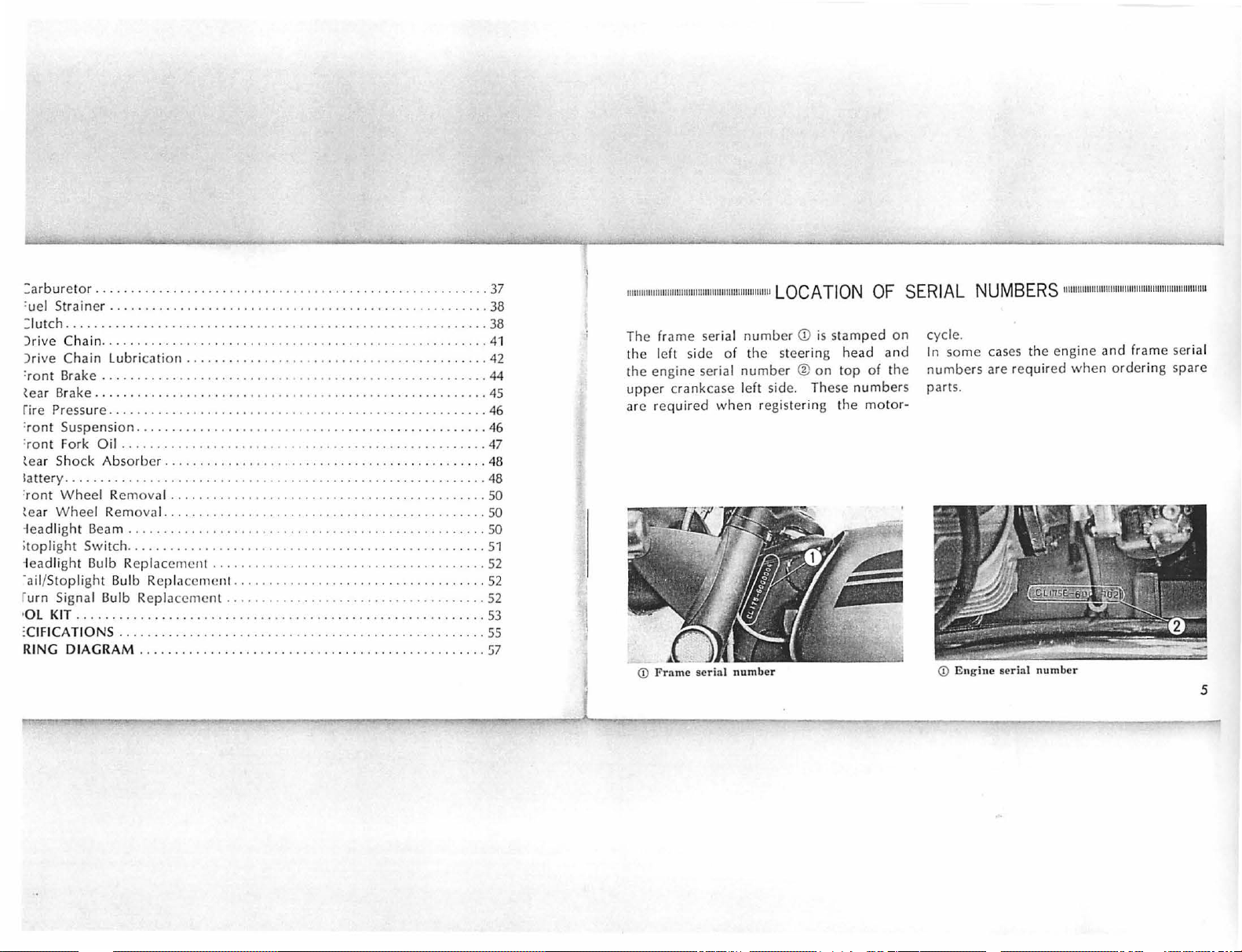
The frame serial
left side of
the
th e engi ne serial
uppe
r crankcase left sid
ir
ed
are requ
(j)
Frame
whe
serial number
11
LOCATION
numb
er
the stee
numb
er ®on
e.
n registe
OF
CD
is
stam p
ed
rin
g head
top
of
These numbers
rin
g the moto
SERIAL
on
and
th e
r-
cycle.
In so
numbe
parts.
(j)
NUMBERS
me
cases
rs
are re
Engine
serial number
11
111111
the engine
quired
when
11111111
11111111111
and
1111111111
111
11111111
frame serial
orde
ring spare
111
1111111111
5
1111111111111111111111111111111111111111111
111
1111111111111111
NOME
NC
7 @
LA
(9)
TUR
dO)
E
1111111111111
111111111111111111111111111111111111111111111111111
111
11111111111111111111m
11
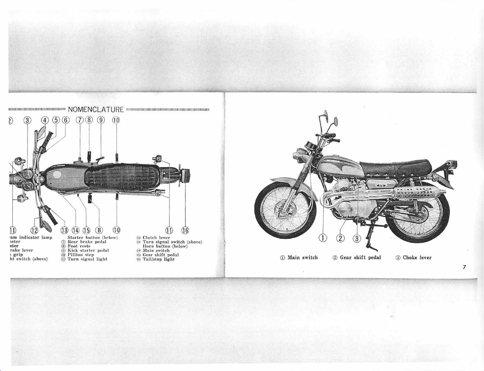
•a m
indicator
1eter
eter
rake
lev
!
ht
er
grip
switch (above)
lamp
S
lnrl
(j)
llcar
®
Pool
® J(ick H
@
l'illion
@
Turn
c r
h11!1011
hrnl11•
rt•
818
lnrlt:r 11t:
•
ll'I'
Hil(nal
®
(1,..low )
111•<1111
<lnl
lil(hl
10
11
1
1>0
C
lut
ch l
113
U•I
11•)
11•1
1
ever
'l'urn signal switch
!l
orn
button
Main switch
Gear
s
hirt pedal
'l'ail/sloJl
light
16
(below)
(a bo ve)
CD
.Main s
witch
® Gea r
shift
pedal @ Choke
lever
7
<D
Kick
starter pedal
®
Fuel valve
@ Rear
brake
peda
11111111111111
11111
111111111
111111
11111111111111
11111111111111
1111111111
OPERA
Tl
NG INS
TR
UCTIONS
1
1111111
111
1111111
1111
111111111111
1111
111111111111111111
11111
111111111r
ELECTRICAL SYSTEM
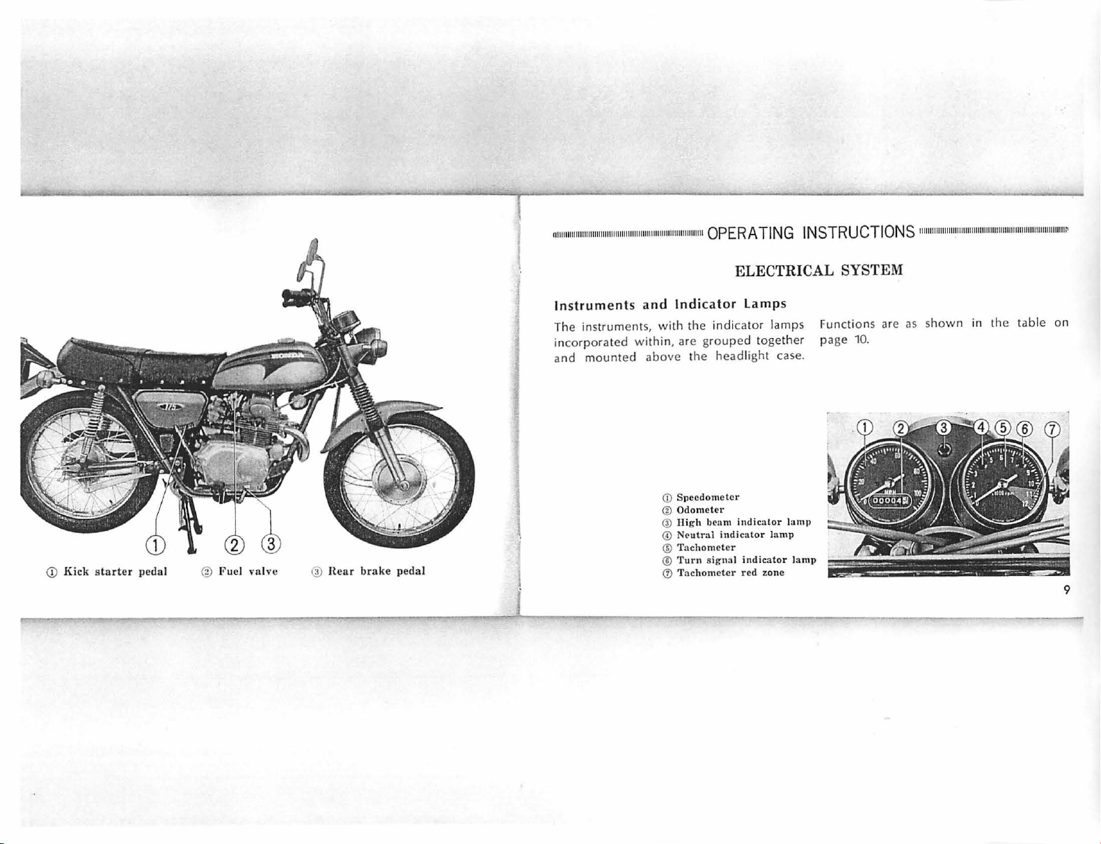
In
struments and
The instr uments, with the indi
incorpora
and
l
ted
mounted
within
above
CD
®
@
© N
®
®
0 T
Ind
icator Lamps
cator
, are grouped
the
headlight
Sp
eedometer
Odom
eter
High
beam indicato
eutral indica
Tachometer
Turn sign
ac
al
hometer red
indicat
lamps
together
case.
r lam)>
tor lamp
or lamp
zone
Functi
page
...
-
~
ons
10.
~
are
as
shown
-·
--
---,
in the table
..
··-...;._;_._,:;;.,-.·-
-
.---~-
on
~
9
•.
Component
I
Speedometer
,-
Odo:~
Hi
gh
beam
l
amp (red
Neu
l
amp (green)
)
tral indicat
ind
icator
or
Indicates speed.
ndic;1t
es total
l
hts when
Lig
Lights with tr;insmi
111
llt'.1dligh
ilc·.
ssi
ru
nct
1g(' .1cc
t 1s on
on
in
ion
umu
high
neutral
lated.
beam.
position
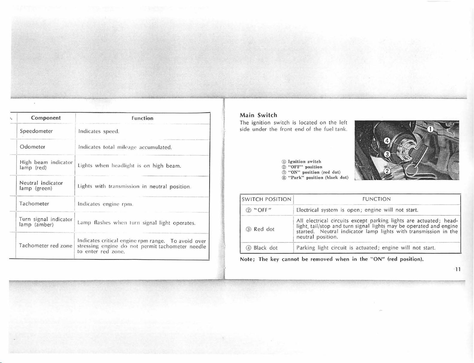
Main
The i
gnition
si
de under
Switch
the front e
switch
CD
@
@
©
is l
Ignit i
"OF
"O
N"
"P
ark
ocated
nd
of the fuel
on
swi
F" pos
pos
ition (red
" pos
on
the left
tank
.
tch
iti
on
dot
(black
)
dot
)
iti
on
I
Tachomet
--
Turn
lamp (amber)
Tachometer
sig
nal
er
indi
red
ca
tor I
zone
lndic,1tcs
1
Lamp fl;i
I
lndic;ites c
stressin
to en ter r
enJ.;inc rpm
slws when
rit
ic;il en
g en
gine
ed
zon
.
turn
gine rpm
do
not
e.
signa l light operates.
range.
perm
To
it tachometer
avoid
ove
needle
SW
ITCH
POSIT
IO
N I
@
"OFF
R
ed dot
"
dot
key cann
---
CD
r
© Black
Not
e; The
Electrical
I
All elec
li
ght,
star
neutral
Parking
ot
be r
sys
tric
al circ
tail
/stop and
ted. Neut
position.
light circuit
emoved
tem is
-
uit
turn signa
ral
indicator lamp
-
whe
FUNCTION
-
ope
n ; engine
s except p ar
l
--
is
actuat
ed ; engine
n
in
th
e "
will
king
lights are actuate
light
~
may
ligh
ts w i
ON"
(red pos
not
start.
be
oper
th transmissi
---
will not
iti
ated
on).
and
start.
--
on
d;
engine
head-
in
the
-
·11
t
Switch
!light switch ©
id
le bar gr
·ch is operated
remo
ving th e hand fr om the
1osi
ti
on
i dur
in
tail lights are not required.
l
" H
"@
d
hts are required. The l
is mou
nted
on the
ip swit
<D,
red dot, is used f
ch housing.
by
the th
umb
g daylight hours when
positions are e
mpl
oyed
ow be;i
"L" is used when approaching
oth
ving an
is for high beam. In
beam indicator
dlig
ht operates only when the
switch is in the
page
er vehicle. The " H"
thi
lamp light
"ON"
11)
<D
" O
FF"
@ "Low beam" posit
@
©
® S
red dol posil i
_.High bca1u" lJosil
Headli
g h t switch
ta
rter button
s position
s.
position
ion
ion
Sla
rtcr
The st.irter
below
With tile s101rtcr
ignition switch
s
1.1
rl(
:r
or
rn
u11
Uullo n
button ® is
the he;i
motor wil
loc
ated directly
dli
ght
~witch
.
1Jut1011
depressed and the
in the.: "ON" positi
l cr;ink the engin
on, th e
e.
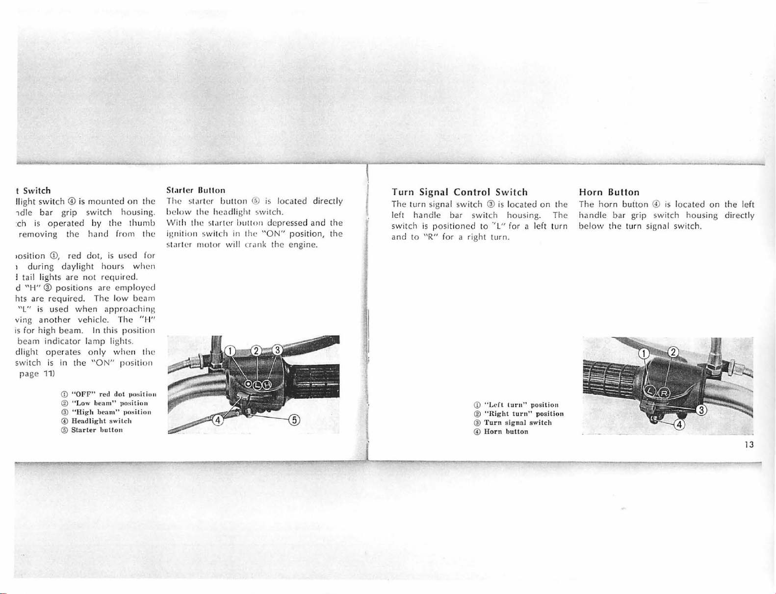
Turn
Signal
The turn
signal switch @ is locate d on the
left handle
switch
and to
is position
"R"
Control
bar swit
ed to
Switch
ch housing. The
.,
L" for a left
for a right turn.
<D
" L
dl
@
"Right
@
Tur
n si
©
Ho
rn
lurn
" posit io
turn" position
gna
l switch
butt
on
turn
11
Horn
Button
The horn
button © is
handle bar gr
below
th e turn signal switch.
ip swit
located on the le
ch housing
dir
ft
ectly
13
 Loading...