

Honda CIVIC SI (2006) Installation Instructions Manual
INSTALLATION
INSTRUCTIONS
Accessory Application Publications No.
AUTOMATIC DAY/NIGHT
MIRROR WITH COMPASS
2006 CIVIC SI
AII 30339
Issue Date
FEB 2006
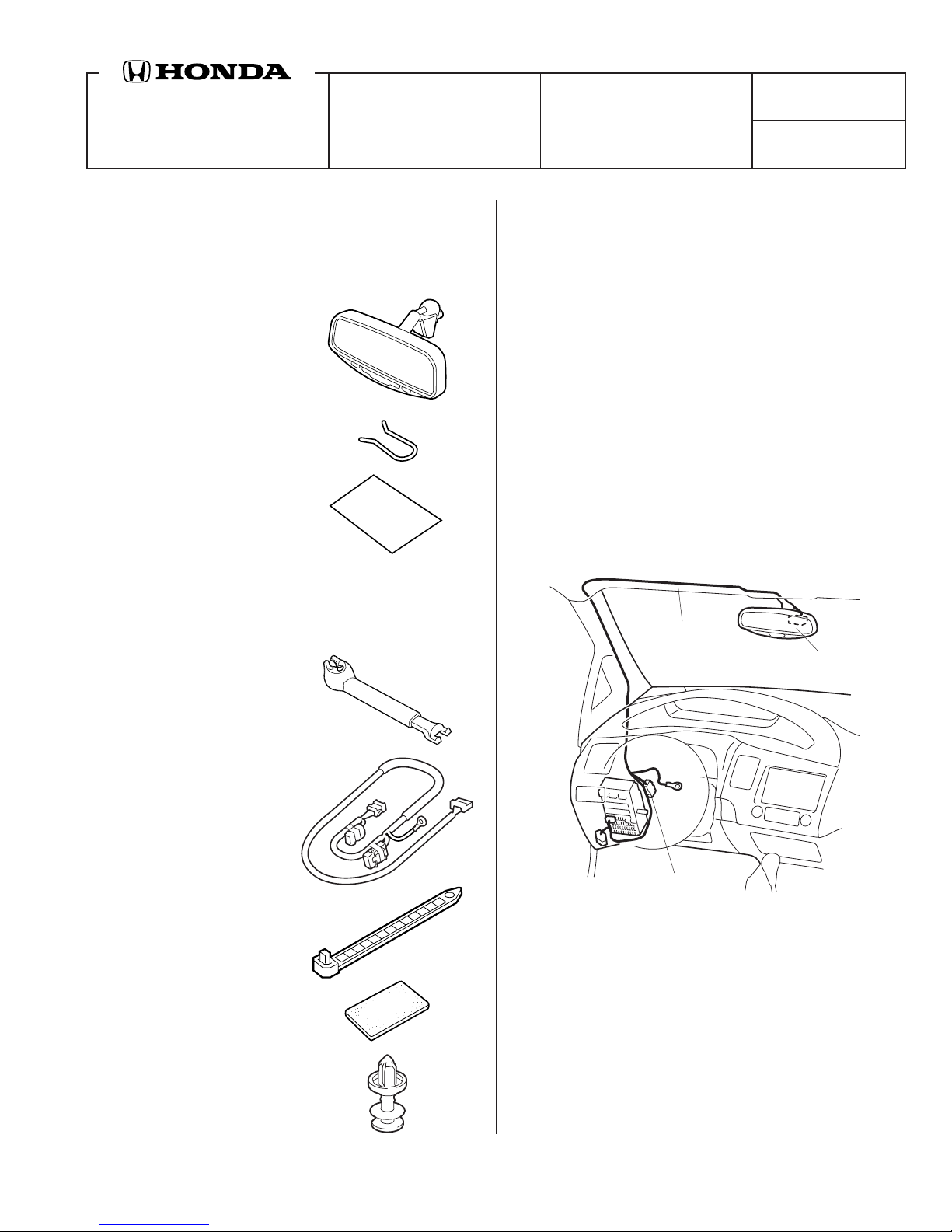
PARTS LIST
Automatic Day/Night Mirror With Compass
P/N 08V03-SDA-100B
Day/Night mirror
Spring
Owner’s Manual
Automatic Day/Night Mirror Attachment Kit
P/N 08V03-SNA-100
Upper and lower covers
TOOLS AND SUPPLIES REQUIRED
Phillips screwdriver
Flat-tip screwdriver
T25 Torx bit
Ratchet
10 mm Socket
Isopropyl alcohol
Shop towel
Piece of steel wire
Tape
Long nose pliers
Small rubber mallet
Tape measure
Illustration of the Day/Night Mirror Installed on the
Vehicle
DAY/NIGHT
MIRROR
HARNESS
DAY/NIGHT
MIRROR
Day/night mirror harness
8 Wire ties
FUSE CASE
(1A)
5217011T
5 EPT sealers
Clip
© 2006 American Honda Motor Co., Inc. - All Rights Reserved. AII 30339 (0602) 1 of 8
08V03-SNA-1000-91
INSTALLATION
Other Vehicles
Customer Information: The information in this
installation instruction is intended for use only by
skilled technicians who have the proper tools,
equipment, and training to correctly and safely add
equipment to your vehicle. These procedures should
not be attempted by “do-it-yourselfers.”
1. Make sure you have the anti-theft code for the
radio, then write down the frequencies for the
preset buttons.
2. Disconnect the negative cable from the battery.
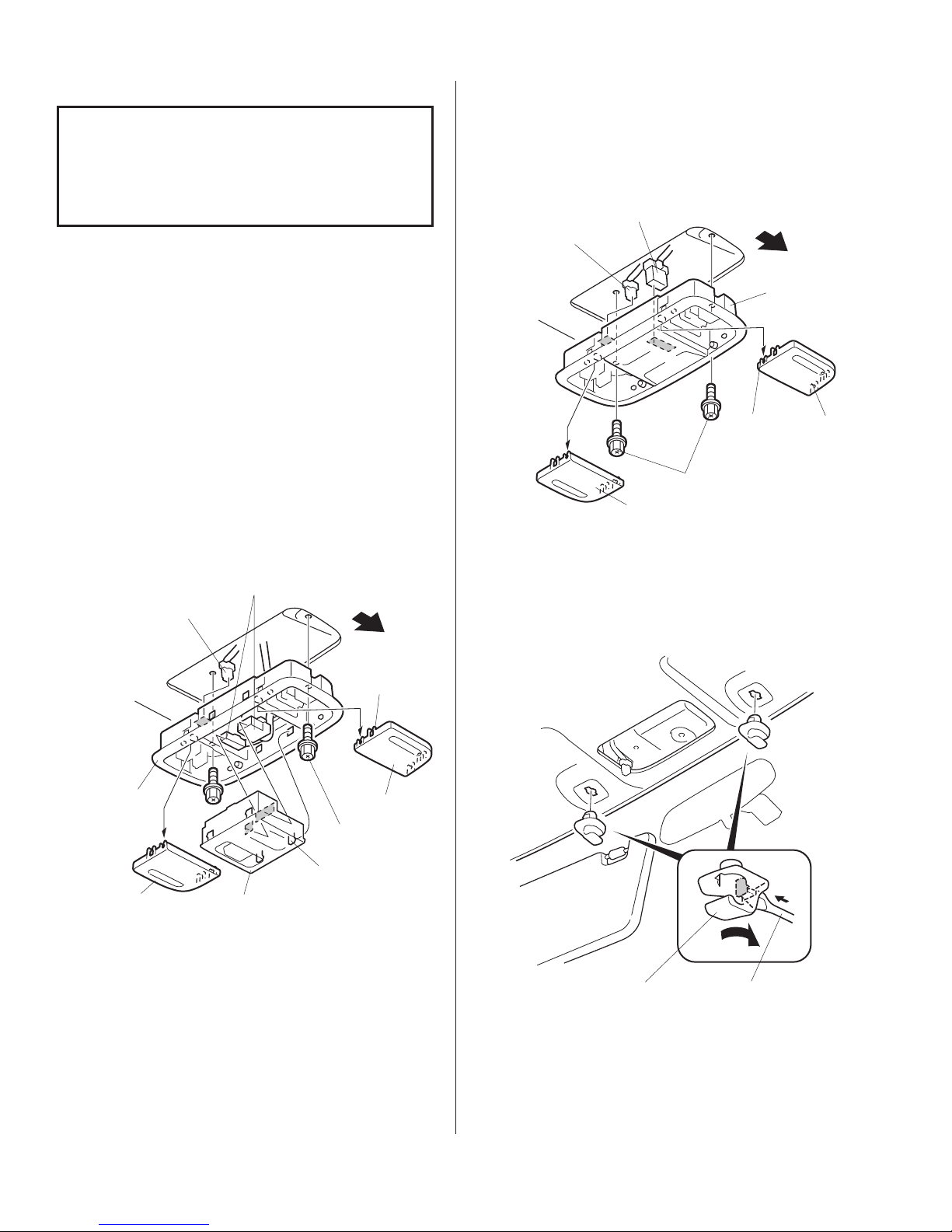
3. If equipped with a map light console, use a small
flat-tip screwdriver to remove the left and right
lens from the map light console. (four retaining
tabs for each lens). Remove the map light
console:
• Remove the two bolts, and unplug the vehicle
3-pin connector. Then remove the switch (four
retaining tabs and unplug the two vehicle
connectors).
With Moonroof and Navigation System
• Remove the two bolts, and unplug the vehicle
connector(s).
VEHICLE
CONNECTOR
VEHICLE
CONNECTOR
(If equipped)
LENS
BOLT
FRONT
MAP
LIGHT
CONSOLE
RETAINING
TABS (4)
LENS
5202590T
VEHICLE 3-PIN
CONNECTOR
MAP
LIGHT
CONSOLE
LENS
VEHICLE
CONNECTOR
SWITCH
RETAINING
TABS (4)
BOLTS
(2)
RETAINING
TABS (4)
FRONT
LENS
5202600T
4. Remove the sunvisor holders. Using a flat-tip
screwdriver, push the hook, turn the holder 90°,
then pull it out.
SUNVISOR
HOLDER
FLAT-TIP
SCREWDRIVER
5217020T
2 of 8 AII 30339 (0602) © 2006 American Honda Motor Co., Inc. - All Rights Reserved.
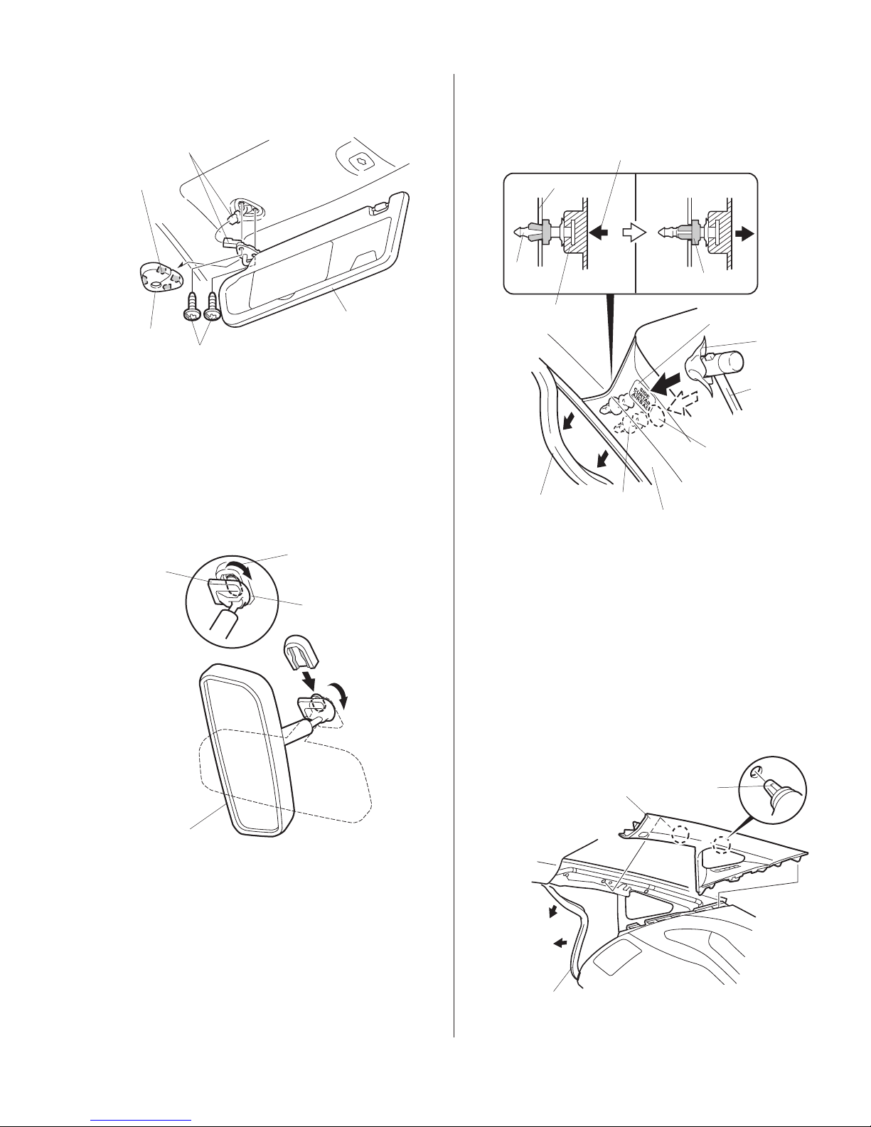
5. Remove the cap from the left sunvisor (four
5202101T
retaining tabs).
9. Pull away the weatherstrip from the left front pillar
trim.
CONNECTOR
RETAINING
TABS (4)
LEFT
CAP
TORX SCREW
SUNVISOR
5217030T
6. Remove the left sunvisor (two T25 Torx screws,
and unplug the vehicle connectors).
7. Repeat steps 5 and 6 to remove the right
sunvisor.
8. Remove the rearview mirror from the holder by
rotating the stay 90° clockwise.
Rotate 90°
STAY
clockwise.
MIRROR
HOLDER
Strike
perpendicularly to
the vehicle.
FRONT
PILLAR
PIN
FRONT
PILLAR TRIM
WEATHERSTRIP
CLIP
LEFT FRONT
PILLAR TRIM
CLIP
STRIKE POINT
for 2-door model
SHOP
TOWEL
RUBBER
MALLET
STRIKE POINT
for 4-door model
5217160T
10. Use a small rubber mallet and a shop towel to
release the clip on the left front pillar trim.
4-door: Tap the trim just under the "SIDE
CURTAIN AIRBAG" marking.
2-door: Tap the trim on the "SIDE CURTAIN
AIRBAG" marking.
11. Pull away the weatherstrip from the left front pillar
trim. Remove the left front pillar trim (two clips).
LEFT FRONT
PILLAR TRIM
REARVIEW
MIRROR
2304041M
WEATHERSTRIP
© 2006 American Honda Motor Co., Inc. - All Rights Reserved. AII 30339 (0602) 3 of 8
CLIPS (2)
 Loading...