

Honda CIVIC AIR CONDITIONER (2002), 80000-S5D-A22, 80000-S5D-C22 Installation Instructions Manual
INSTALLATION
INSTRUCTIONS
Accessory Application Publications No.
AIR CONDITIONER
CIVIC
2- AND 4-DOOR
AII 24158
Issue Date
SEP 2002
What’s New
The installation instructions for the 2003 Civic
A/C are the same as the 2002 model. However,
the A/C kit numbers are different because of
improvements to the wire length on the
compressor:
• 80000-S5D-A22 for U.S.
• 80000-S5D-C22 for Canada
TOOLS AND SUPPLIES REQUIRED
Duct tape
Hacksaw blade
Trim clip remover
Open-end wrench set
Screwdrivers
Socket wrench set
Torque wrench
Tension gauge
Refrigerant oil (R-12 mineral oil or R-134a PAG oil)
Fender, floor, and seat covers
HFC-134a refrigerant recovery/recycling/charging
station
Gloves
Eye protection (face shield or safety goggles)
Electronic leak detector
NOTICE
S Use only
HFC-134a in this system; do not
use CFC 12 (Freon); do not install parts
designed for use in a
CFC system.
S Use a charging station. A/C charging
stations and refrigerant recovery/recycling
stations minimize the release of
HFCs to the atmosphere. Use them for all A/C
CFCs and
charging and service work according to the
manufacturers’ instructions.
S Do not overcharge. This system requires
only the amount of
HFC-134a refrigerant
shown below. If you overcharge the system,
the engine and the
A/C will malfunction.
500 to 550 grams
0.50 to 0.55 kilograms
1.1 to 1.2 pounds
17.6 to 19.4 ounces
INSTALLATION
Customer Information: The information in
these instructions is intended for use only by
skilled technicians who have the proper tools,
equipment, and training to correctly and safely
add equipment to your car. These procedures
should not be attempted by doĆitĆyourselfers."
NOTE:
S Make sure you have the anti-theft code for
the audio system.
S Write down the customer’s radio station
presets; the radio memory will be erased
when you disconnect the battery.
S Make sure you install the right part. Use the
illustrations on pages 2 and 3 as a guide to
check the parts before you install them.
S Don’t remove plugs and caps from fittings
until the parts are ready to connect. This
will keep out moisture and dirt which could
cause wear and damage.
During Installation:
S Before you connect any line or hose,
check and lube its O-ring. Make sure the
O-ring is on the fitting, put a few drops of
refrigerant oil on the O-ring, then connect the
fitting.
S You may use either type of refrigerant oil to
lubricate O-rings and fittings.
S If you add or replace refrigerant oil in the
system, use only this
PAG oil: Sanden SP-10,
P/N 38897-P13-A01.
S Route and secure the lines and hoses
properly; maintain clearance between them
and surrounding parts.
S Use two wrenches to tighten or loosen
fittings; hold one fitting in place while you
tighten the other one against it.
NOTICE
Don’t overtighten; you could
damage the fittings. Before you tighten a
fitting, check the torque listed for it. If leaks
are caused by faulty O-rings, overtightening
the fitting won’t help.
S Before you connect each electrical
connector, check its terminals. Make sure
the terminals aren’t bent or out of place.
2002 American Honda Motor Co., Inc. – All Rights Reserved AII 24158 (0209) 8000X-S5D-C22 1 of 24
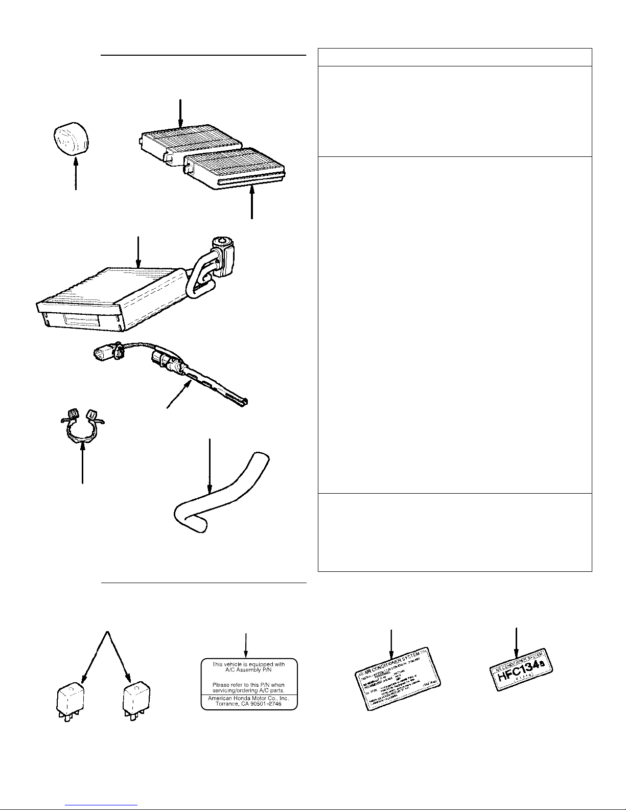
Group A
GROUP PAR T P/N QUANTITY
79601ĆS5AĆ003
53747ĆSA5Ć003
80290ĆS5DĆA01
80210ĆS5DĆG02
80560ĆS5AĆ941
80271ĆS5AĆ000
80295ĆS5DĆA01
Drain hose clip
A/C button
A
Evaporator
Drain hose
Dust and pollen filter A
Dust and pollen filter B
Evaporator sensor
Wire ties
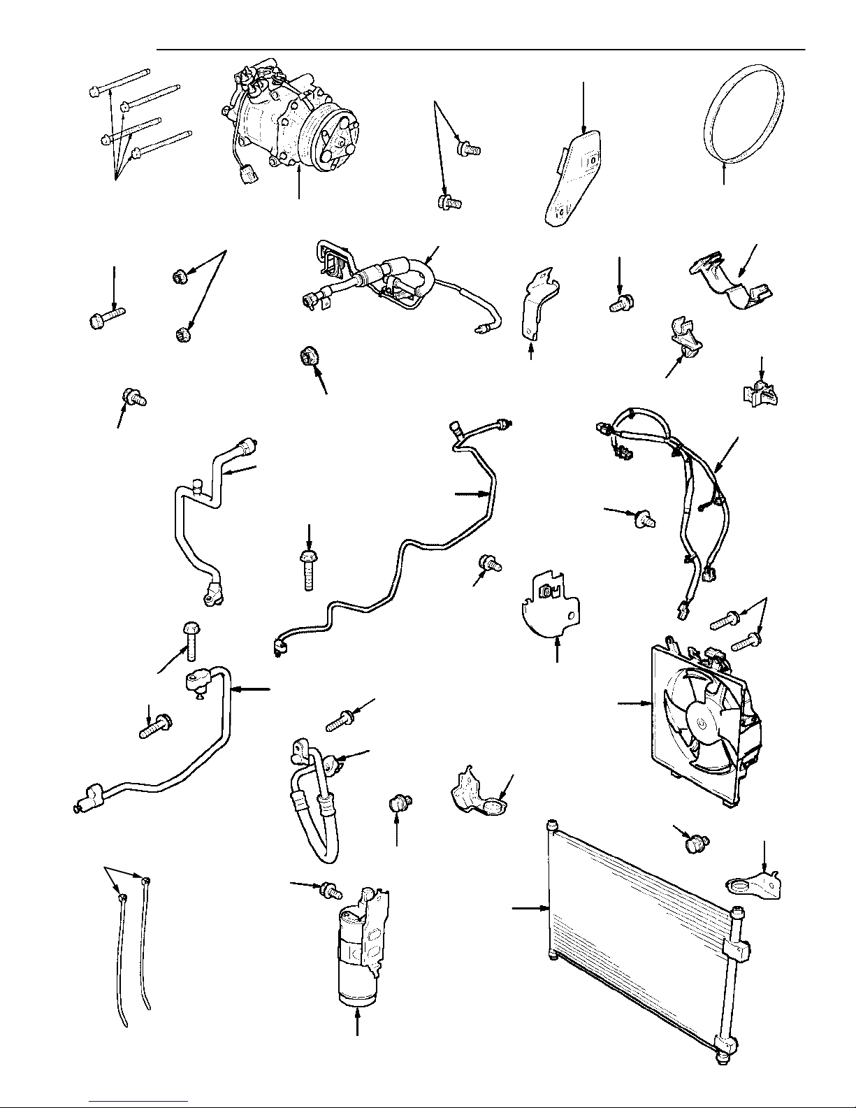
Condenser fan assembly
B
Compressor
Compressor belt
Heat insulator
Condenser assembly
Right condenser bracket
Left condenser bracket
Suction line
Discharge hose
A/C suction line and receiver line B
Condenser line
Receiver line
Receiver
Suction hose clamp A
Suction hose bracket
Suction line bracket
Receiver line clip A
Receiver line clip B
A/C wire harness
Flange bolts, 8 x 100 mm
Ground bolt, 6 x 12 mm (brassĆcolored)
Paint cutting nut, 6 mm (yellowĆtinted)
WasherĆbolt, 6 x 12 mm (yellowĆtinted)
WasherĆbolts, 6 x 16 mm (grayĆcolored)
Flange bolts, 6 x 12 mm (yellowĆtinted)
Flange bolts, 6 x 25 mm (yellowĆtinted)
Flange bolt, 6 x 30 mm (yellowĆtinted)
Power relay (4P)
Information label (Canada)
C
Information label (USA)
A/C kit identification label (USA)
53747ĆSA5Ć003
79601ĆS5AĆ003
80210ĆS5DĆG03
80271ĆS5AĆ000
80290ĆS5DĆA01
80295ĆS5DĆA01
80560ĆS5AĆ941
08F13ĆS84100013
38605ĆPMMĆA12
38800ĆPLMĆA12
38920ĆPLRĆ004
38935ĆPLMĆA00
80100ĆS5AĆ003
80107ĆS5AĆ000
80108ĆS5AĆ000
80311ĆS5DĆA12
80315ĆS5AĆ013
80320ĆS5DĆA12
80331ĆS5DĆA11
80341ĆS5DĆA11
80350ĆS5DĆA01
80360ĆS5AĆA00
80361ĆS5AĆA00
80363ĆS5AĆA01
80381ĆS5AĆA01
80387ĆSM4ĆA01
80460ĆS5AĆA00
90023ĆP2AĆ000
90153ĆSE0Ć003
90361ĆSV4Ć003
93403Ć06012Ć08
93403Ć06016Ć05
95701Ć06012Ć08
95701Ć06025Ć08
95701Ć06030Ć08
39794ĆS0KĆA01
80050ĆSP0Ć000
80050ĆSR3ĆH00
8005XĆS5DĆA21
1
1
1
1
1
1
1
2
1
1
1
1
1
1
1
1
1
1
1
1
1
1
1
1
1
1
1
4
1
3
1
7
2
4
1
2
1
1
1
Group C
39794-S0K-A01
2 of 24
8005XĆS5DĆA21
AII 24158 (0209)
80050ĆSR3ĆH00
2002 American Honda Motor Co., Inc – All Rights Reserved
80050ĆSP0Ć000
Group B
90023ĆP2AĆ000
(YellowĆtinted)
95701Ć06030Ć08
93403Ć06016Ć05
(GrayĆcolored)
38800ĆPLMĆA02
(YellowĆtinted)
90361ĆSV4Ć003
90361ĆSV4Ć003
(YellowĆtinted)
80311ĆS5DĆA12
(Yellow tinted)
95701Ć06012Ć08
80320ĆS5DĆA12
38935ĆPLMĆA00
80361ĆS5AĆA00
(YellowĆtinted)
93403Ć06012Ć08
80381ĆS5AĆA01
38920ĆPLRĆ004
80360ĆS5AĆA00
80387ĆSM4ĆA01
80460ĆS5AĆA00
(YellowĆtinted)
95701Ć06025Ć08
08F13-S8410013
93403Ć06016Ć05
(GrayĆcolored)
(YellowĆtinted)
95701Ć06025Ć08
80331ĆS5DĆA11
80341ĆS5DĆA11
93403Ć06016Ć05
(Gray colored)
(YellowĆtinted)
95701Ć06025Ć08
80315ĆS5AĆ013
93403Ć06016Ć05
(GrayĆcolored)
80100ĆS5AĆ003
(BrassĆcolored)
90153ĆSE0Ć003
80363ĆS5AĆA01
38605ĆPMMĆA11
80107ĆS5AĆ000
93403Ć06016Ć05
(GrayĆcolored)
(GrayĆcolored)
93403Ć06016Ć05
80108ĆS5AĆ000
2002 American Honda Motor Co., Inc – All Rights Reserved
80350ĆS5DĆA01
AII 24158 (0209)
3 of 24
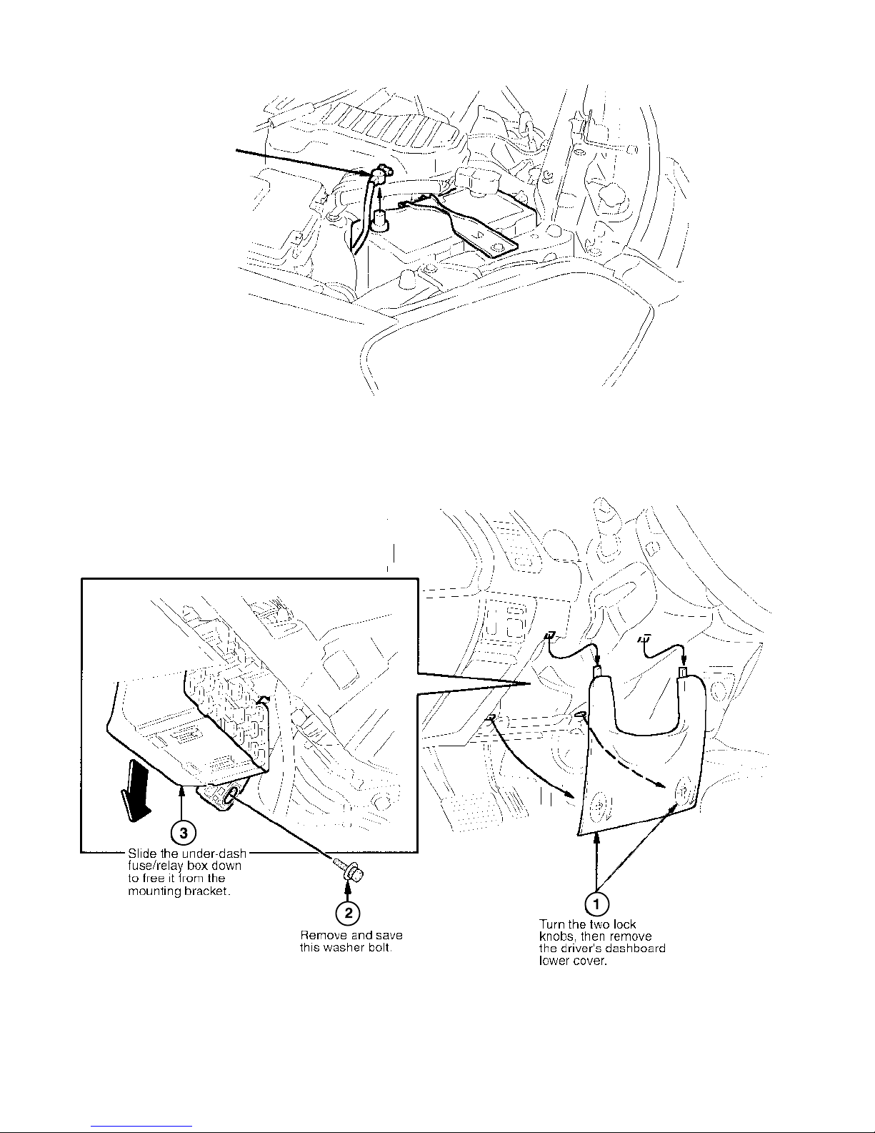
1. Disconnect the battery.
Remove the
negative cable
from the battery.
2. Remove the driver’s dashboard lower cover and the under-dash fuse/relay box.
4 of 24
AII 24158 (0209)
2002 American Honda Motor Co., Inc – All Rights Reserved
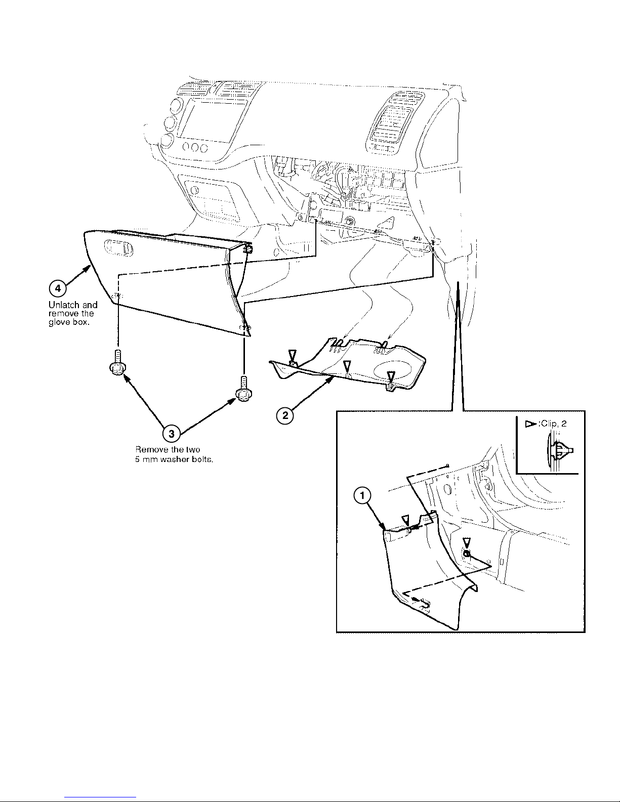
3. Remove the passenger’s dashboard lower cover and the glove box.
Remove the cover by
pulling down on its front
edge to release the
three clips, then pulling
it toward you to release
the two rear pins.
Remove the
passenger’s
kick panel
(two clips).
2002 American Honda Motor Co., Inc – All Rights Reserved
AII 24158 (0209)
5 of 24
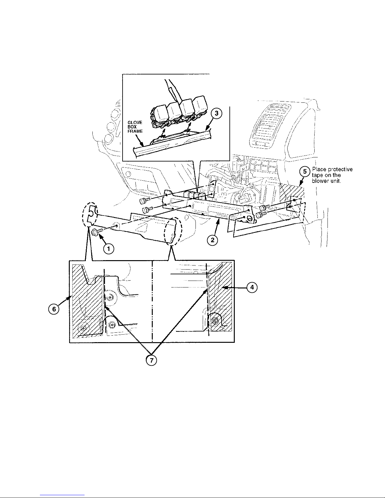
4. Remove the glove box frame and plastic cross-piece.
Release these
two lock tabs,
then remove the
relay assembly
from the glove
box frame.
Place protective
tape on the
driver’s side of
the glove box
opening.
Remove and
discard this 5 mm
washer bolt.
Remove the glove
box frame (four bolts).
Move aside any vehicle harness
that may be in the way, and use a
hacksaw blade to carefully cut
through the plastic cross-piece in
the areas shown. Remove and
discard the plastic cross-piece and
the protective tape.
Place protective tape
(duct tape) on the
passenger’s side of the
glove box opening.
6 of 24
AII 24158 (0209)
2002 American Honda Motor Co., Inc – All Rights Reserved
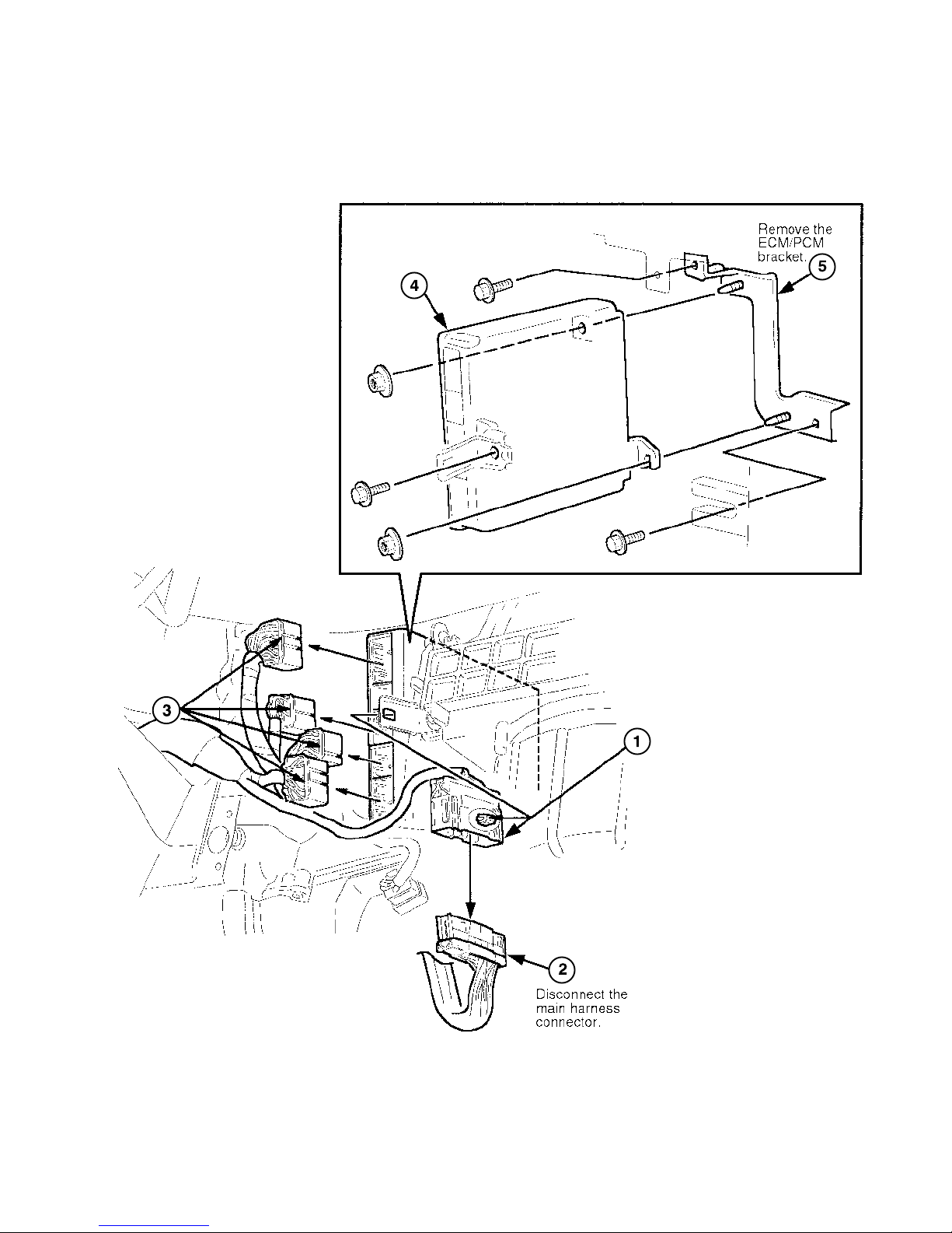
5. Remove the ECM/PCM unit and the bracket.
Remove the
ECM/PCM.
Disconnect these
connectors from
the ECM/PCM.
Remove the main
harness connector
from its bracket.
2002 American Honda Motor Co., Inc – All Rights Reserved
AII 24158 (0209)
7 of 24
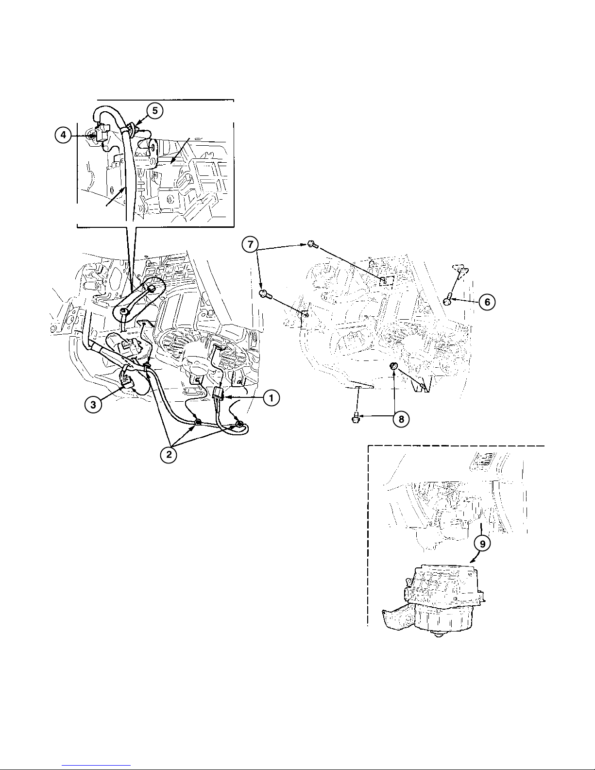
6. Prepare to install the evaporator.
Disconnect
the recirculation
control motor
7P connector.
Remove this wire harness
clip from the blower.
BLOWER
VEHICLE
HARNESS
Disconnect the
power transistor
4P connector.
Remove these
wire harness
clips from the
blower.
Remove and
save these
washer bolts.
Disconnect
the blower
motor 2P
connector.
Remove and save
this 6 x 20 mm
washer bolt.
Remove and save this paintcutting 6 mm nut and 6 x 16 mm
washer-bolt.
8 of 24
AII 24158 (0209)
Remove
the blower
from the
dashboard.
2002 American Honda Motor Co., Inc – All Rights Reserved
 Loading...