

PREFACE
This SERVICE MANUAL
has
been prepared as a
"
SERVICE GUIDE " for the mechanic responsible
for
the upkeep of the HONDA OUTBOARD
MOTOR B75
.
It is compiled into nine sections and summarizes
the procedures for disassembling. inspecting and
reassembling the components of the machine
.
Careful attention to the instructions given herein
will result in better. safer service work
.
ALL INFORMATION. ILLUSTRATIONS. DIRECTIONS AND SPECIFICATIONS INCLUDED IN
THIS PUBLICATION ARE BASED ON THE
LATEST PRODUCT INFORMATION AVAILABLE
AT THE TIME OF APPROVAL FOR PRINTING
.
HONDA MOTOR CO., LTD . RESERVES THE
RIGHT TO MAKE CHANGES AT ANY TIME
WITHOUT NOTICE AND WITHOUT INCURRING
ANY OBLIGATION WHATEVER
.
NO PART OF THIS PUBLICATION MAY BE REPRODUCED WITHOUT WRITTEN PERMISSION
.
HONDA
MOTOR
CO.,
LTD
.
Service
Publications
Office
Date
of
Issue:
Feb
.
1977
@
HONDA
MOTOR
CO.,
LTD
.
CONTENTS
liJ
THE 9 RULES FOR EFFECTIVE
......................
SERVICE WORK
POWER HEAD AND LOWER UNIT
REMOVAL AND INSTALLATION
....
1
.
Lower Unit
........................
2
.
Power
Head
........................
POWER HEAD
........................
......................
.
1
Recoil Starter
2
.
Carburetor
and
Intake Manifold
......
......................
.
3
Cooling System
4
.
Cylinder Head and Camshaft
........
5
.
Cylinder Block, Pistons
and
Crankshaft
6
.
Electrical System
....................
7 . Oil Pump and Fuel Pump
............
B]
LOWER UNIT
........................
.
............................
1
Propeller
2
.
Water Pump and Water Tubes
......
3
.
Gear Case and Shift Mechanism
......
........................
SWIVEL UNIT
1
.
Steering Handle
....................
2
.
Swivel Case, Mount Frame and Stem
Brackets
............................
3
.
Oil Case
............................
4
.
Tilt and Reverse
Lock
Mechanisms
.
.
5
.
Shift Shaft
..........................
................
[61
POST-SERVICE TESTS
Q
FUEL TANKS
........................
......................
[81
SERVICE DATA
........................
.
1
Special Tools
................
. 2
Maintenance Schedule
....................
.
3
Lubrication Chart
................
.
4
Torque Specification
........................
.
5
Service Data
....................
.
6
Trouble Shooting
........................
.
7 Specifications
........
B]
REMOTE CONTROL
(Optional)
.............
B75
K3
Service Information
Page:
1 . Honda
B75K2-B75K3
Outboard Motors Manual
.
Download this Manual
121
POWER
HEAD
AND LOWER UNIT REMOVAL AND
INSTALLATION
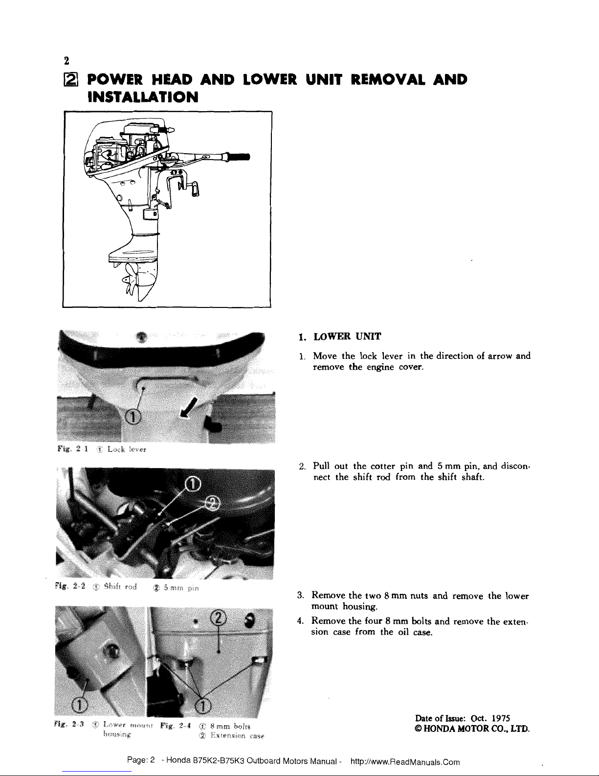
1.
LOWER
UNIT
1.
Move the lock lever in the direction of arrow and
remove the engine cover.
2.
Pull out the cotter pin and 5 mm pin, and disconnect the shift rod from the shift shaft.
3.
Remove the two 8 mm nuts and remove the lower
mount housing.
4.
Remove the four 8 mm bolts and remove the extension case from the oil case.
Date of
Issue:
Oct.
1975
@
HONDA
MOTOR
CO..
LTD.
Page: 2 - Honda B75K2-B75K3 Outboard Motors Manual
-
Download this Manual

5.
CYLINDER
BLOCK,
PISTONS
AND
CRANKSHAFT
Disassembly
1.
Remove the engine.
(See
page
3.)
2.
Remove the recoil starter.
(See
page
5.)
3.
Remove the carburetor and intake manifold.
(See
pages
9
thru.
11.)
4.
Remove the oil pick-up pipe
and
disconnect the
exhaust pipe.
5.
Remove the cylinder head.
(See
pages
13
thru
14.)
6.
Remove the three
6
rnm
bolts and ratchet pulley.
Install the flywheel puller (Tool
No.
07933-9350000)
to the flywheel and loosen the
12
rnm
special nut
to remove flywheel from the crankshaft.
7.
Remove the primary coil and clamp.
8.
Straighten the locking tab of the
22
nun
lock washer,
remove the
lock
nut, the timing pulley
and
belt.
9.
Remove the ignition coil.
10.
Disconnect the oil return
tube,
breather tube
A
and
water tube from the cylinder block.
Date
of
Issue:
Oct.
1975
Q
HONDA
MOTOR
CO.,
LTD.
Page:
18
-
Honda
B75K2-B75K3
Outboard
Motors
Manual
-
Download this Manual
 Loading...